EP4470955A1 - Textile machine - Google Patents
Textile machine Download PDFInfo
- Publication number
- EP4470955A1 EP4470955A1 EP24178807.4A EP24178807A EP4470955A1 EP 4470955 A1 EP4470955 A1 EP 4470955A1 EP 24178807 A EP24178807 A EP 24178807A EP 4470955 A1 EP4470955 A1 EP 4470955A1
- Authority
- EP
- European Patent Office
- Prior art keywords
- space
- opening
- base member
- shutter
- textile machine
- Prior art date
- Legal status (The legal status is an assumption and is not a legal conclusion. Google has not performed a legal analysis and makes no representation as to the accuracy of the status listed.)
- Withdrawn
Links
Images




Classifications
-
- B—PERFORMING OPERATIONS; TRANSPORTING
- B65—CONVEYING; PACKING; STORING; HANDLING THIN OR FILAMENTARY MATERIAL
- B65H—HANDLING THIN OR FILAMENTARY MATERIAL, e.g. SHEETS, WEBS, CABLES
- B65H54/00—Winding, coiling, or depositing filamentary material
- B65H54/70—Other constructional features of yarn-winding machines
- B65H54/707—Suction generating system
-
- B—PERFORMING OPERATIONS; TRANSPORTING
- B65—CONVEYING; PACKING; STORING; HANDLING THIN OR FILAMENTARY MATERIAL
- B65H—HANDLING THIN OR FILAMENTARY MATERIAL, e.g. SHEETS, WEBS, CABLES
- B65H54/00—Winding, coiling, or depositing filamentary material
- B65H54/86—Arrangements for taking-up waste material before or after winding or depositing
- B65H54/88—Arrangements for taking-up waste material before or after winding or depositing by means of pneumatic arrangements, e.g. suction guns
-
- B—PERFORMING OPERATIONS; TRANSPORTING
- B65—CONVEYING; PACKING; STORING; HANDLING THIN OR FILAMENTARY MATERIAL
- B65H—HANDLING THIN OR FILAMENTARY MATERIAL, e.g. SHEETS, WEBS, CABLES
- B65H54/00—Winding, coiling, or depositing filamentary material
- B65H54/70—Other constructional features of yarn-winding machines
- B65H54/702—Arrangements for confining or removing dust
-
- B—PERFORMING OPERATIONS; TRANSPORTING
- B65—CONVEYING; PACKING; STORING; HANDLING THIN OR FILAMENTARY MATERIAL
- B65H—HANDLING THIN OR FILAMENTARY MATERIAL, e.g. SHEETS, WEBS, CABLES
- B65H54/00—Winding, coiling, or depositing filamentary material
- B65H54/70—Other constructional features of yarn-winding machines
- B65H54/705—Arrangements for reducing hairyness of the filamentary material
-
- B—PERFORMING OPERATIONS; TRANSPORTING
- B65—CONVEYING; PACKING; STORING; HANDLING THIN OR FILAMENTARY MATERIAL
- B65H—HANDLING THIN OR FILAMENTARY MATERIAL, e.g. SHEETS, WEBS, CABLES
- B65H54/00—Winding, coiling, or depositing filamentary material
- B65H54/70—Other constructional features of yarn-winding machines
- B65H54/71—Arrangements for severing filamentary materials
-
- B—PERFORMING OPERATIONS; TRANSPORTING
- B65—CONVEYING; PACKING; STORING; HANDLING THIN OR FILAMENTARY MATERIAL
- B65H—HANDLING THIN OR FILAMENTARY MATERIAL, e.g. SHEETS, WEBS, CABLES
- B65H67/00—Replacing or removing cores, receptacles, or completed packages at paying-out, winding, or depositing stations
- B65H67/08—Automatic end-finding and material-interconnecting arrangements
- B65H67/081—Automatic end-finding and material-interconnecting arrangements acting after interruption of the winding process, e.g. yarn breakage, yarn cut or package replacement
- B65H67/085—Automatic end-finding and material-interconnecting arrangements acting after interruption of the winding process, e.g. yarn breakage, yarn cut or package replacement end-finding at the take-up package, e.g. by suction and reverse package rotation
-
- B—PERFORMING OPERATIONS; TRANSPORTING
- B65—CONVEYING; PACKING; STORING; HANDLING THIN OR FILAMENTARY MATERIAL
- B65H—HANDLING THIN OR FILAMENTARY MATERIAL, e.g. SHEETS, WEBS, CABLES
- B65H69/00—Methods of, or devices for, interconnecting successive lengths of material; Knot-tying devices ;Control of the correct working of the interconnecting device
-
- B—PERFORMING OPERATIONS; TRANSPORTING
- B65—CONVEYING; PACKING; STORING; HANDLING THIN OR FILAMENTARY MATERIAL
- B65H—HANDLING THIN OR FILAMENTARY MATERIAL, e.g. SHEETS, WEBS, CABLES
- B65H71/00—Moistening, sizing, oiling, waxing, colouring or drying filamentary material as additional measures during package formation
-
- B—PERFORMING OPERATIONS; TRANSPORTING
- B65—CONVEYING; PACKING; STORING; HANDLING THIN OR FILAMENTARY MATERIAL
- B65H—HANDLING THIN OR FILAMENTARY MATERIAL, e.g. SHEETS, WEBS, CABLES
- B65H2701/00—Handled material; Storage means
- B65H2701/10—Handled articles or webs
- B65H2701/17—Nature of material
- B65H2701/174—Textile; fibres
-
- B—PERFORMING OPERATIONS; TRANSPORTING
- B65—CONVEYING; PACKING; STORING; HANDLING THIN OR FILAMENTARY MATERIAL
- B65H—HANDLING THIN OR FILAMENTARY MATERIAL, e.g. SHEETS, WEBS, CABLES
- B65H2701/00—Handled material; Storage means
- B65H2701/30—Handled filamentary material
- B65H2701/31—Textiles threads or artificial strands of filaments
Definitions
- the present invention relates to a textile machine including a device that winds yarn to form a package.
- a textile machine including a device that winds yarn to form a package.
- This textile machine is equipped with a yarn catching mechanism that catches cut yarn by sucking air when the yarn breaks during package formation.
- the textile machine is equipped with a cleaning pipe that removes a foreign object adhered to the yarn, by sucking air, to clean the yarn.
- the textile machine is equipped with a suction source that generates air suction force for the yarn catching mechanism and the cleaning pipe.
- the textile machine is equipped with a shutter device that switches between a state where the cleaning pipe is disconnected with the suction source while the yarn catching mechanism is connected with the suction source, and a state where the yarn catching mechanism is disconnected with the suction source while the cleaning pipe is connected with the suction source (see, for example, JP 2018-127345 A ).
- This shutter device includes a base member having an opening that is connected to the suction source, a cover member having an opening that is connected to the yarn catching mechanism and an opening that is connected to the cleaning pipe, and a shutter member that closes the opening connected to the yarn catching mechanism or closes the opening connected to the cleaning pipe.
- a gap is formed between the base member and the cover member so that the shutter member can move.
- the gap between the base member and the cover member forms one space, and the opening connected to the yarn catching mechanism and the opening connected to the cleaning pipe are disposed close to each other. Therefore, when one of the openings is closed by the shutter member, the other opening cannot be separated completely from the one opening.
- an air suction force of the suction source exerts not only on the yarn catching mechanism but also on the cleaning pipe, and a foreign object (e.g., cotton dust) sucked by the cleaning pipe may flow into the gap between the base member and the cover member. This foreign object may disturb movement of the shutter member, and hence the above two openings may become unable to be appropriately closed by the shutter member.
- a textile machine of the present invention includes a device configured to wind yarn to form a package.
- the textile machine includes a first suction mechanism, a second suction mechanism, a suction source, and a shutter device.
- the first suction mechanism catches broken yarn by sucking air.
- the second suction mechanism cleans yarn by sucking air.
- the suction source generates air suction force for the first suction mechanism and the second suction mechanism.
- the shutter device is disposed between the suction source and the first suction mechanism and the second suction mechanism, and is configured to select connection between the first suction mechanism and the suction source or connection between the second suction mechanism and the suction source.
- the shutter device includes a base member, a cover member, and a shutter member.
- the base member has a first opening and a second opening.
- the cover member has a first space forming part and a second space forming part.
- the first space forming part forms a first space with the base member, the first space is connected to the suction source via the first opening.
- the second space forming part forms a second space with the base member, the second space is connected to the suction source via the second opening.
- the shutter member is disposed between the base member and the cover member, and is configured to move between the first opening and the second opening to close the first opening or close the second opening.
- the first space forming part has a third opening to connect the first space to the first suction mechanism.
- the second space forming part has a fourth opening to connect the second space to the second suction mechanism.
- the first space and the second space are separately disposed.
- a gap for the shutter member to move is formed at a first boundary part and between the first space forming part and the base member, the first boundary part is a boundary between the first space and external space, and a gap for the shutter member to move is formed at a second boundary part and between the second space forming part and the base member, the second boundary member is a boundary between the second space and external space.
- a seal member is disposed in the gaps.
- the base member has the first opening and the second opening.
- the cover member has the first space forming part that forms the first space with the base member, the first space is connected to the suction source via the first opening, and the second space forming part that forms the second space with the base member, the second space is connected to the suction source via the second opening.
- the first space forming part has the third opening to connect the first space to the first suction mechanism, while the second space forming part has the fourth opening to connect the second space to the second suction mechanism.
- the first space and the second space are separately disposed.
- the first space connected to the third opening and the second space connected to the fourth opening can be separated from each other in space. As a result, it is possible to prevent the air suction force generated at one of the third opening and the fourth opening from affecting the other.
- a gap for the shutter member to move is formed at the first boundary part and between the first space forming part and the base member, the first boundary part is a boundary between the first space and external space.
- a gap for the shutter member to move is formed at the second boundary part and between the second space forming part and the base member, the second boundary part is a boundary between the second space and external space.
- the seal member is disposed in the gaps. In this way, the first space and the second space can be separated from each other more securely, and it is possible to prevent air from entering from outside into the first space and the second space. As a result, power saving of the textile machine can be realized.
- the first space may include an outer periphery space.
- the outer periphery space is a space formed by an outer periphery part of the first space forming part to have a gap in which an outer periphery part of the shutter member moves.
- the gap of the outer periphery space may have a width corresponding to thickness of the shutter member.
- the first space may include an extended space.
- the extended space has a gap larger than that of the outer periphery space in a direction of thickness of the shutter member. In this way, even if a foreign object enters in the first space, the extended space can store a sufficient amount of foreign objects, and hence it is possible to prevent accumulated foreign objects from disturbing the movement of the shutter member.
- the gap of the first boundary part may have a width corresponding to thickness of the shutter member. In this way, the shutter member can move in the first boundary part, and it is possible to prevent a foreign object to enter from outside into the first space.
- the cover member may be made of resin. In this way, freedom in design of the cover member can be improved.
- the base member may be provided with a static eliminating member that is electrically connected to ground. In this way, electric charge of the shutter device can be prevented.
- the base member may include a first fixing member and a second fixing member.
- the first fixing member pushes and fixes a part of the cover member near the first boundary part to the base member.
- the second fixing member pushes and fixes a part of cover member near the second boundary part to the base member.
- the cover member can be securely fixed to the base member, and the gaps of the first boundary part and the second boundary part can be minimized. As a result, it is possible to prevent air or the like from entering through the gaps of the first boundary part and the second boundary part into the first space and the second space.
- the seal member may be made of a felt material.
- the felt material has a high sliding property, and hence the first space and the second space can be securely separated from each other, while the shutter member can move smoothly.
- the second space may be provided with a protruding part protruding from the base member to define an origin position of the shutter member. In this way, the origin position of the shutter member can be securely determined.
- the protruding part may have a truncated cone shape that is thinner towards the tip. In this way, it is possible to prevent a foreign object entering in the second space from wrapping around the protruding part.
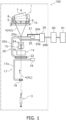
- Fig. 1 is a diagram illustrating a structure of the textile machine 100.
- the textile machine 100 includes a winding device 1.
- the winding device 1 is a device that winds yarn 4 unraveled from a yarn feeding bobbin 3 around a winding pipe 6 while traversing the same by a traverse drum 5 to form a package 7.
- the textile machine 100 of Fig. 1 includes only one winding device 1, but a lot of winding devices 1 of this type are arranged on a machine stand to constitute the textile machine 100.
- the winding device 1 includes a cradle 8 that supports the winding pipe 6 in an attachable and detachable manner, and the traverse drum 5 that rotates at a predetermined rotational frequency while contacting a circumferential surface of the winding pipe 6 or a circumferential surface of the package 7.
- the cradle 8 holds and supports both ends of the winding pipe 6 in a rotatable manner.
- the cradle 8 is configured to be pivotable about a pivot shaft 10, so that an increase in a diameter of the package 7 due to taking up of the yarn 4 around the winding pipe 6 or the package 7 can be absorbed by pivoting of the cradle 8.
- the circumferential surface of the traverse drum 5 is provided with a traverse groove 9 that is configured to traverse the yarn 4 with respect to the winding pipe 6 or the package 7. The winding pipe 6 or the package 7 is driven to rotate when the traverse drum 5 rotates.
- the winding device 1 includes a yarn splicing device 14, a yarn clearer 15, a waxing device 24, and a cleaning pipe 25, which are disposed in a running path of the yarn 4 between the yarn feeding bobbin 3 and the traverse drum 5, in order from the yarn feeding bobbin 3 side.
- the yarn splicing device 14 is configured to perform yarn splicing between lower yarn 4L as the yarn 4 on the yarn feeding bobbin 3 side and upper yarn 4U as the yarn 4 on the package 7 side, when the yarn clearer 15 detects a yarn defect and cuts the yarn, or when the yarn 4 from the yarn feeding bobbin 3 breaks.
- the yarn clearer 15 is used for detecting a defect of the yarn 4, and it detects thickness of the yarn 4 passing a detection unit part of the yarn clearer 15, using an appropriate sensor, and analyzes a signal from this sensor to detect a yarn defect.
- the yarn clearer 15 is provided with a cutter 16 that is configured to cut the yarn 4 promptly when a yarn defect is detected.
- a lower yarn sucking and catching guide mechanism 17 which sucks and catches the lower yarn 4L on the yarn feeding bobbin 3 side to guide the same to the yarn splicing device 14, and an upper yarn sucking and catching guide mechanism 20 (an example of a first suction mechanism), which sucks and catches the upper yarn 4U on the package 7 side to guide the same to the yarn splicing device 14.
- the upper yarn sucking and catching guide mechanism 20 has a pipe-like structure and has a suction mouth 22 at the distal end.
- the upper yarn sucking and catching guide mechanism 20 is constituted of a pipe 20a extending from the suction mouth 22, a shaft 21 that supports the pipe 20a in a pivotable manner, and a link pipe 20b that links the pipe 20a and a shutter device 29 to each other.
- the lower yarn sucking and catching guide mechanism 17 also has a pipe-like structure, and has an air intake 19 at the distal end.
- the lower yarn sucking and catching guide mechanism 17 includes a relay pipe 17a disposed in a pivotable manner about an shaft 18 upward and downward, and a link pipe that links the relay pipe 17a and a the duct 60 to each other.
- the waxing device 24 is a device that applies appropriate wax to the running yarn 4.
- the cleaning pipe 25 is a device that sucks and removes a foreign object adhered to the running yarn 4.
- a proximal end 25b of the cleaning pipe 25 is connected to the shutter device 29, and a suction inlet 25a is formed at the distal end of the cleaning pipe 25.
- the suction inlet 25a of the cleaning pipe 25 is close to the running yarn 4 between the waxing device 24 and the traverse drum 5.
- the winding device 1 includes the upper yarn sucking and catching guide mechanism 20 (i.e., the suction mouth 22), which sucks and catches the upper yarn 4U and guides the same to the yarn splicing device 14, as the first suction mechanism, and includes the cleaning pipe 25 as a yarn trap, which sucks a foreign object adhered to the running yarn 4, as a second suction mechanism.
- the upper yarn sucking and catching guide mechanism 20 i.e., the suction mouth 22
- the cleaning pipe 25 as a yarn trap, which sucks a foreign object adhered to the running yarn 4, as a second suction mechanism.
- the textile machine 100 is equipped with the duct 60 and a suction source 61.
- the duct 60 extends along a direction in which the plurality of winding devices 1 are arranged in parallel.
- the suction source 61 is linked to the duct 60, and generates a negative pressure in the duct 60.
- Each of the winding devices 1 in the textile machine 100 includes the shutter device 29.
- the shutter device 29 is disposed between the suction source 61 and the cleaning pipe 25 as well as the upper yarn sucking and catching guide mechanism 20.
- the shutter device 29 is connected to the duct 60 and is connected to the suction source 61 via the duct 60.
- the shutter device 29 is connected to the upper yarn sucking and catching guide mechanism 20 via the link pipe 20b.
- the shutter device 29 is connected to the cleaning pipe 25 at the proximal end 25b.
- the shutter device 29 selects connection between the upper yarn sucking and catching guide mechanism 20 and the duct 60 or connection between the cleaning pipe 25 and the duct 60.
- the suction source 61 When the upper yarn sucking and catching guide mechanism 20 is connected to the duct 60, the suction source 61 generates an air suction force at the suction mouth 22 of the upper yarn sucking and catching guide mechanism 20 via the duct 60. Using the suction force generated at the suction mouth 22, it is possible to suck and catch the upper yarn 4U at the suction mouth 22.
- the suction source 61 when the cleaning pipe 25 is connected to the duct 60, the suction source 61 generates the air suction force at the suction inlet 25a of the cleaning pipe 25 via the duct 60. Using the suction force generated at the suction inlet 25a, it is possible to suck and remove a foreign object from the yarn 4. In addition, the suction inlet 25a can suck and remove yarn waste generated between the traverse drum 5 and the yarn clearer 15.
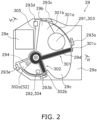
- Fig. 2 is a plan view of the shutter device 29.
- the shutter device 29 includes a base member 29a, a cover member 29b, and a shutter member 29c.
- the base member 29a is a member that arranges the shutter member 29c.
- the base member 29a is made of a resin material.
- Fig. 3 is a plan view of the base member 29a.
- the base member 29a includes a first opening 291, a second opening 292, a plurality of fixing parts 293a to 293 e, a protruding part 294, and a static eliminating member 295.
- the first opening 291 and the second opening 292 are openings that penetrate the base member 29a.
- a connection part 296 is disposed on a back surface side of the base member 29a (the opposite side of the side of the base member 29a on which the cover member 29b is disposed), and the first opening 291 and the second opening 292 are connected to one end part of the connection part 296.
- the other end part of the connection part 296 is provided with an elastic member such as rubber, for example.
- This elastic member is connected to the duct 60, so that the other end part of the connection part 296 is connected to the duct 60.
- the first opening 291 and the second opening 292 are connected to the suction source 61 via the connection part 296 and the duct 60.
- the first opening 291 and the second opening 292 are formed in the base member 29a at positions apart from each other.
- the first opening 291 can be formed in an upper part of the base member 29a, while the second opening 292 can be formed in a lower part of the base member 29a. In this way, by disposing the first opening 291 and the second opening 292 apart from each other, it is possible to prevent the suction force at one opening from affecting the other opening.
- the plurality of fixing parts 293a to 293e fix the cover member 29b to the base member 29a.
- the fixing parts 293c to 293e sandwich an edge part 305 of the cover member 29b between itself and the base member 29a, so as to fix the cover member 29b.
- the fixing parts 293c to 293e fix the cover member 29b at positions apart from a boundary part.
- the fixing part 293a (an example of a first fixing member) is disposed at a position close to a first end part 301c (first boundary part) of the cover member 29b disposed on the base member 29a, and pushes a part (a nail part 305a) near the first end part 301c of the edge part 305 of the cover member 29b to the base member 29a to fix the same.
- a surface of the fixing part 293a facing the nail part 305a is provided with a protrusion, which prevents the cover member 29b from moving with respect to the base member 29a, together with a protrusion provided to the nail part 305a.
- the fixing part 293a is fixed from the back surface side of the base member 29a to the base member 29a with a screw, and by adjusting the fastening force of the screw, it is possible to adjust the force of the fixing part 293a pushing the edge part 305 of the cover member 29b.
- the fixing part 293a is a snap type fixing member, for example.
- the fixing part 293b (an example of a second fixing member) is disposed at a position close to a second boundary part of the cover member 29b disposed on the base member 29a, and pushes a part (a nail part 305b) near the second boundary part of the edge part 305 of the cover member 29b to the base member 29a, so as to fix the same.
- a surface of the fixing part 293b facing the nail part 305b is provided with a protrusion, which prevents the cover member 29b from moving with respect to the base member 29a, together with a protrusion provided to the nail part 305b.
- the fixing part 293a is fixed from the back surface side of the base member 29a to the base member 29a with a screw, and by adjusting the fastening force of the screw, it is possible to adjust the force of the fixing part 293b pushing the edge part 305 of the cover member 29b.
- the fixing part 293b is a snap type fixing member, for example.
- first end part 301c and a second end part 302b of the cover member 29b form the first boundary part and the second boundary part, respectively.
- the first boundary part and the second boundary part are provided with gaps corresponding to thickness of the shutter member 29c so that the shutter member 29c can move.
- the first boundary part and the second boundary part are boundaries between external space and a first space S1 and a second space S2, respectively, and hence the gaps of these boundary parts are preferably minimized, to prevent air or the like from entering through these gaps.
- the edge part 305 (the nail part 305a) of the cover member 29b near the first boundary part is fixed to the base member 29a with the fixing part 293a
- the edge part 305 (the nail part 305b) of the cover member 29b near the second boundary part is fixed to the base member 29a with the fixing part 293b
- the cover member 29b can be securely fixed to the base member 29a, and the gaps of the first boundary part and the second boundary part can be minimized.
- the protruding part 294 is a protrusion that protrudes from the base member 29a.
- the shutter device 29 has an origin position where the shutter member 29c is rotated a predetermined amount in a reverse direction from a state where the shutter member 29c abuts the protruding part 294.
- the protruding part 294 is disposed to define the origin position of the shutter member 29c.
- the protruding part 294 has substantially a truncated cone shape that is thinner towards the tip from the base part. In this way, a foreign object such as cotton dust hardly wrap around the protruding part 294.
- the protruding part 294 has a flat surface part formed on the side to which the shutter member 29c abuts.
- the static eliminating member 295 is a member having electrical conductivity fixed to the back surface side of the base member 29a.
- the static eliminating member 295 is made of a metal material (such as copper), for example.
- the static eliminating member 295 is connected to ground. In this way, it is possible to prevent electrification of the shutter device 29 that is partly made of a resin material.
- the cover member 29b is a member that is disposed on the base member 29a and forms the first space S1 and the second space S2.
- the cover member 29b is made of a resin material.
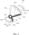
- Fig. 4 is a plan view of the cover member 29b.
- the cover member 29b has a first space forming part 301, a second space forming part 302, and the edge part 305.
- the first space forming part 301 is formed to protrude from the edge part 305 that contacts the base member 29a.
- the first space forming part 301 covers the first opening 291 of the base member 29a, and forms the first space S1 that is connected to the suction source 61 via the first opening 291.
- the first space forming part 301 has a fan shape.
- the first space forming part 301 has an outer periphery part 301a corresponding to an outer periphery of the fan shape, an inner periphery part 301b corresponding to an inner periphery of the fan shape, and the first end part 301c corresponding to a radius part of the fan shape.
- the outer periphery part 301a slightly protrudes from the edge part 305.
- the inner periphery part 301b largely protrudes from the edge part 305 and is disposed higher than the outer periphery part 301a.
- the outer periphery part 301a forms a space (referred to as an outer periphery space S11) between itself and the base member 29a, as illustrated in Fig. 5 .
- the outer periphery space S11 is a space that allows the outer periphery part of the shutter member 29c to move.
- the outer periphery space S11 has a small gap that has a width corresponding to the thickness of the shutter member 29c.
- Fig. 5 is a VI-VI cross-sectional view of the shutter device 29 illustrated in Fig. 2 .
- the outer periphery part of the shutter member 29c can move in the outer periphery space S 11, and a foreign object that has entered in the first space S1 (an extended space S12 described later) can hardly enter in the outer periphery space S11.
- a foreign object e.g., cotton dust
- the inner periphery part 301b forms a large space (referred to as the extended space S12) between itself and the base member 29a.
- the extended space S12 forms a gap that is larger than the gap formed in the outer periphery space S11 described above. In other words, the extended space S12 forms the gap that is larger than the outer periphery space S11 in the thickness direction of the shutter member 29c.
- the extended space S12 can store a sufficient amount of foreign objects, and hence it is possible to prevent accumulated foreign objects from disturbing the movement of the shutter member 29c. In addition, it is also possible to suck and remove foreign objects in the extended space S12 through the first opening 291.
- the first end part 301c is an end part corresponding to the radius part of the first space forming part 301 of the fan shape.
- the first end part 301c forms the first boundary part between itself and the base member 29a, which is a boundary part between the first space S1 and the external space.
- the first boundary part has a gap that has a width corresponding to the thickness of the shutter member 29c.
- the shutter member 29c moves in the first boundary part and enters in the first space S1.
- the gap of the first boundary part is set corresponding to the thickness of the shutter member, the shutter member 29c can move in the first boundary part, and it is possible to prevent a foreign object from entering from outside through the first boundary part into the first space S1.
- the first space forming part 301 is provided with a third opening 303.
- the third opening 303 is connected to the first space S1 and is connected to the link pipe 20b.
- the third opening 303 connects the first space S1 to the upper yarn sucking and catching guide mechanism 20.
- the upper yarn sucking and catching guide mechanism 20 is connected to the first opening 291 via the first space S1.
- the upper yarn sucking and catching guide mechanism 20 can suck through the first opening 291.
- the second space forming part 302 is formed to protrude from the edge part 305 that contacts the base member 29a.
- the second space forming part 302 is disposed separately from the first space forming part 301. Specifically, with respect to the center of the cover member 29b, the second space forming part 302 is disposed on the opposite side of the first space forming part 301.
- the second space forming part 302 has a space forming part 302a and the second end part 302b.
- the space forming part 302a covers the second opening 292 of the base member 29a, to form the second space S2 that is connected to the suction source 61 via the second opening 292.
- the protruding part 294 formed on the base member 29a is housed in the second space S2.
- the space forming part 302a has a fan shape that is smaller than the first space forming part 301.
- the second end part 302b is an end part corresponding to the radius part of the second space forming part 302 of the fan shape.
- the second end part 302b forms the second boundary part between itself and the base member 29a, which is a boundary part between the second space S2 and the external space.
- the second boundary part has a gap that has a width corresponding to the thickness of the shutter member 29c.
- the shutter member 29c moves in the second boundary part and enters in the second space S2.
- the gap of the second boundary part is set corresponding to the thickness of the shutter member, the shutter member 29c can move in the second boundary part, and it is possible to prevent a foreign object from entering from outside into the first space S1.
- the space forming part 302a is provided with a fourth opening 304.
- the fourth opening 304 is connected to the second space S2, and is connected to the base part of the cleaning pipe 25. In other words, the fourth opening 304 connects the second space S2 to the cleaning pipe 25.
- the cleaning pipe 25 is connected to the second opening 292 via the second space S2. In other words, the cleaning pipe 25 can suck through the second opening 292.
- the first space forming part 301 and the second space forming part 302 are disposed separately from each other.
- the first space S1 connected to the third opening 303 and the second space S2 connected to the fourth opening 304 can be separated from each other in space.
- the edge part 305 corresponds to an outer edge part of the cover member 29b. When the cover member 29b is disposed on the base member 29a, the edge part 305 abuts the base member 29a.
- the edge part 305 has a plurality of nail parts 305a to 305d.
- the nail part 305a is disposed between the base member 29a and the fixing part 293a.
- the fixing part 293a pushes the nail part 305a to the base member 29a.
- the cover member 29b is fixed to the base member 29a.
- the nail part 305b is disposed between the base member 29a and the fixing part 293b.
- the fixing part 293b pushes the nail part 305b to the base member 29a. In this way, in a vicinity of the second boundary part, the cover member 29b is fixed to the base member 29a.
- the nail part 305c is inserted between the base member 29a and the fixing part 293c.
- the cover member 29b is fixed to the base member 29a at a position apart from the first boundary part of the first space forming part 301.
- the nail part 305d is inserted between the base member 29a and the fixing part 293e.
- the cover member 29b is fixed to the base member 29a at a position apart from the second boundary part (the second end part 302b) of the second space forming part 302.
- the gap formed in the first boundary part, the gap formed in the second boundary part, and a seal member 29d are disposed.
- the seal member 29d is fixed to a surface that faces the first end part 301c of the first space forming part 301 that forms the first boundary part, and the base member 29a of the second end part 302b of the second space forming part 302 that forms the second boundary part.
- a felt material having high sliding property can be used, for example.
- the seal member 29d can be made by cutting the felt material to have a shape of the first end part 301c and the second end part 302b.
- the felt material has high sliding property, by using the felt material as the seal member 29d, the first space and the second space can be securely separated from each other, and the shutter member 29c can move smoothly.
- a rubber material having good sealing performance can be used, for example.
- the first space S1 and the second space S2 can be separated from outside more securely.
- the seal member 29d By disposing the seal member 29d in the gaps of the first boundary part and the second boundary part, the gap of the first boundary part and the gap of the second boundary part can be closed by the seal member 29d. As a result, the first space S1 formed by the first space forming part 301 and the second space S2 formed by the second space forming part 302 can be securely separated from each other. In addition, it is possible to prevent air and a foreign object from entering from outside into the first space S1 and the second space S2.
- the shutter member 29c is disposed between the base member 29a and the cover member 29b, and moves between the first opening 291 and the second opening 292 to close the first opening 291 or to close the second opening 292.
- the second opening 292 is opened so that the suction source 61 generates air suction force in the cleaning pipe 25.
- the first opening 291 is opened so that the suction source 61 generates air suction force in the upper yarn sucking and catching guide mechanism 20.
- Fig. 6 is a diagram illustrating the shutter member 29c disposed on the base member 29a.
- the shutter member 29c is a plate-shaped member in which a large semicircle part and a small fan shape part are combined.
- the shutter member 29c is attached to the base member 29a in a rotatable manner about a rotation axis A1.
- the shutter member 29c rotates about the rotation axis A1 when being driven by a motor 29e attached to the base member 29a.
- the motor 29e is a stepping motor, for example.
- Fig. 7 is a diagram illustrating a state where the shutter member 29c fully closes the first opening 291 and fully opens the second opening 292.
- Fig. 8 is a diagram illustrating a state where the shutter member 29c fully closes both the first opening 291 and the second opening 292.
- the first opening 291 and the second opening 292 can be adjusted at any opening degrees.
- the origin position of the shutter member 29c can be determined as follows, for example. First, the shutter member 29c is driven by the motor 29e to rotate in the first direction D1 so that the shutter member 29c abuts the protruding part 294. After the shutter member 29c abuts the protruding part 294, the motor 29e is controlled to further rotate in the first direction D1 (out of step). After that, the motor 29e is rotated in the reverse direction so that the shutter member 29c is rotated in the second direction D2, and the position where the first opening 291 is fully opened while the second opening 292 is fully closed is determined as the origin position of the shutter member 29c.
- the shutter device 29 described above can also be applied to a textile machine other than the textile machine 100 including the winding device 1. For instance, it can also be applied to a textile machine including a spinning device.
- the shutter device includes a base member (e.g., the base member 29a), a cover member (e.g., the cover member 29b), and a shutter member (e.g., the shutter member 29c).
- the base member has a first opening (e.g., the first opening 291) and a second opening (e.g., the second opening 292).
- the cover member has a first space forming part (e.g., the first space forming part 301) and a second space forming part (e.g., the second space forming part 302).
- the first space forming part forms a first space (e.g., the first space S1) with the base member, the first space is connected to the suction source via the first opening.
- the second space forming part forms a second space (e.g., the second space S2) with the base member, the second space is connected to the suction source via the second opening.
- the shutter member is disposed between the base member and the cover member, and is configured to move between the first opening and the second opening to close the first opening or close the second opening.
- the first space forming part has a third opening (e.g., the third opening 303) to connect the first space to the first suction mechanism.
- the second space forming part has a fourth opening (e.g., the fourth opening 304) to connect the second space to the second suction mechanism.
- the first space and the second space are separately disposed.
- a gap for the shutter member to move is formed at a first boundary part and between the first space forming part and the base member, the first boundary part is a boundary between the first space and external space
- a gap for the shutter member to move is formed at a second boundary part and between the second space forming part and the base member, the second boundary part is a boundary between the second space and external space.
- a seal member e.g., the seal member 29d
- the seal member 29d is disposed in the gaps.
- the base member has the first opening and the second opening.
- the cover member has the first space forming part that forms the first space with the base member, the first space is connected to the suction source via the first opening, and a second space forming part that forms a second space with the base member, the second space is connected to the suction source via the second opening.
- the first space forming part has the third opening to connect the first space to the first suction mechanism, while the second space forming part has a fourth opening to connect the second space to the second suction mechanism.
- the first space and the second space are separately disposed.
- the first space connected to the third opening and the second space connected to the fourth opening can be separated in space.
- a gap for the shutter member to move is formed at a first boundary part and between the first space forming part and the base member, the first boundary part is a boundary between the first space and external space.
- a gap for the shutter member to move is formed at a second boundary part and between the second space forming part and the base member, the second boundary part is a boundary between the second space and external space.
- the seal member is disposed in the gaps. In this way, the first space and the second space can be separated more securely, and it is possible to prevent air from entering from outside into the first space and the second space. As a result, power saving of the textile machine can be realized.
- the first space may include an outer periphery space (e.g., the outer periphery space S11).
- the outer periphery space is a space formed by an outer periphery part of the first space forming part (e.g., the outer periphery part 301a) to have a gap in which an outer periphery part of the shutter member moves.
- the gap of the outer periphery space may have a width corresponding to thickness of the shutter member.
- the first space may include an extended space (e.g., the extended space S12).
- the extended space has a gap larger than that of the outer periphery space in a direction of thickness of the shutter member. In this way, even if a foreign object enters in the first space, the extended space can store a sufficient amount of foreign objects, and hence it is possible to prevent accumulated foreign objects from disturbing the movement of the shutter member.
- the gap of the first boundary part may have a width corresponding to thickness of the shutter member. In this way, the shutter member can move in the first boundary part, and it is possible to prevent a foreign object to enter from outside into the first space.
- the cover member may be made of resin. In this way, freedom in design of the cover member can be improved.
- the base member may be provided with a static eliminating member (e.g., the static eliminating member 295) that is electrically connected to ground. In this way, electric charge of the shutter device can be prevented.
- a static eliminating member e.g., the static eliminating member 295
- the base member may include a first fixing member (e.g., the fixing part 293a) and a second fixing member (e.g., the fixing part 293b).
- the first fixing member pushes and fixes a part of the cover member near the first boundary part to the base member.
- the second fixing member pushes and fixes a part of cover member near the second boundary part to the base member.
- the cover member can be securely fixed to the base member, and the gaps of the first boundary part and the second boundary part can be minimized.
- the seal member may be made of a felt material.
- the felt material has high sliding property, and hence the first space and the second space can be securely separated from each other, and the shutter member can move smoothly.
- the second space may be provided with a protruding part (e.g., the protruding part 294) protruding from the base member to define an origin position of the shutter member. In this way, the origin position of the shutter member can be securely determined.
- a protruding part e.g., the protruding part 294
- the protruding part may have a truncated cone shape that is thinner towards the tip. In this way, it is possible to prevent a foreign object entering in the second space from wrapping around the protruding part.
- the present invention can be widely applied to textile machines.
Landscapes
- Engineering & Computer Science (AREA)
- Textile Engineering (AREA)
- Spinning Or Twisting Of Yarns (AREA)
- Replacing, Conveying, And Pick-Finding For Filamentary Materials (AREA)
- Filamentary Materials, Packages, And Safety Devices Therefor (AREA)
Abstract
To prevent air suction force generated at one opening from affecting the other opening, a textile machine includes an upper yarn sucking and catching guide mechanism, a cleaning pipe, a suction source, and a shutter device 29. The shutter device 29 includes a base member 29a having a first opening 291 and a second opening 292, a shutter member 29c that closes the first opening 291 or the second opening 292, and a cover member 29b including a first space forming part 301 that forms a first space connected to the suction source via the first opening 291, and has a third opening 303, and a second space forming part 302 that forms a second space S2 connected to the suction source via the second opening 292, and has a fourth opening 304. The first space and the second space S2 are separately disposed. A seal member 29d is disposed in gaps formed at a first boundary part between the first space and external space S2, and at a second boundary part between the second space S2 and external space.
Description
- The present invention relates to a textile machine including a device that winds yarn to form a package.
- Conventionally, there is known a textile machine including a device that winds yarn to form a package. This textile machine is equipped with a yarn catching mechanism that catches cut yarn by sucking air when the yarn breaks during package formation. In addition, the textile machine is equipped with a cleaning pipe that removes a foreign object adhered to the yarn, by sucking air, to clean the yarn. Further, the textile machine is equipped with a suction source that generates air suction force for the yarn catching mechanism and the cleaning pipe.
- In addition, the textile machine is equipped with a shutter device that switches between a state where the cleaning pipe is disconnected with the suction source while the yarn catching mechanism is connected with the suction source, and a state where the yarn catching mechanism is disconnected with the suction source while the cleaning pipe is connected with the suction source (see, for example,
JP 2018-127345 A - This shutter device includes a base member having an opening that is connected to the suction source, a cover member having an opening that is connected to the yarn catching mechanism and an opening that is connected to the cleaning pipe, and a shutter member that closes the opening connected to the yarn catching mechanism or closes the opening connected to the cleaning pipe. In addition, a gap is formed between the base member and the cover member so that the shutter member can move.
- In the shutter device provided to the conventional textile machine, the gap between the base member and the cover member forms one space, and the opening connected to the yarn catching mechanism and the opening connected to the cleaning pipe are disposed close to each other. Therefore, when one of the openings is closed by the shutter member, the other opening cannot be separated completely from the one opening. As a result, for example, when the opening connected to the cleaning pipe is closed while the opening connected to the yarn catching mechanism is opened, an air suction force of the suction source exerts not only on the yarn catching mechanism but also on the cleaning pipe, and a foreign object (e.g., cotton dust) sucked by the cleaning pipe may flow into the gap between the base member and the cover member. This foreign object may disturb movement of the shutter member, and hence the above two openings may become unable to be appropriately closed by the shutter member.
- It is an object of the present invention to prevent the air suction force generated at one opening from affecting the other opening, in the shutter device having the opening connected to the yarn catching mechanism and the opening connected to the cleaning pipe.
- Hereinafter, as means for solving the problem, a plurality of embodiments are described. These embodiments can be arbitrarily combined as necessary.
- A textile machine of the present invention includes a device configured to wind yarn to form a package. The textile machine includes a first suction mechanism, a second suction mechanism, a suction source, and a shutter device. The first suction mechanism catches broken yarn by sucking air. The second suction mechanism cleans yarn by sucking air. The suction source generates air suction force for the first suction mechanism and the second suction mechanism. The shutter device is disposed between the suction source and the first suction mechanism and the second suction mechanism, and is configured to select connection between the first suction mechanism and the suction source or connection between the second suction mechanism and the suction source.
- The shutter device includes a base member, a cover member, and a shutter member. The base member has a first opening and a second opening. The cover member has a first space forming part and a second space forming part. The first space forming part forms a first space with the base member, the first space is connected to the suction source via the first opening. The second space forming part forms a second space with the base member, the second space is connected to the suction source via the second opening. The shutter member is disposed between the base member and the cover member, and is configured to move between the first opening and the second opening to close the first opening or close the second opening. The first space forming part has a third opening to connect the first space to the first suction mechanism. The second space forming part has a fourth opening to connect the second space to the second suction mechanism.
- In the textile machine described above, the first space and the second space are separately disposed. In addition, a gap for the shutter member to move is formed at a first boundary part and between the first space forming part and the base member, the first boundary part is a boundary between the first space and external space, and a gap for the shutter member to move is formed at a second boundary part and between the second space forming part and the base member, the second boundary member is a boundary between the second space and external space. In addition, a seal member is disposed in the gaps.
- In the textile machine described above, the base member has the first opening and the second opening. In addition, the cover member has the first space forming part that forms the first space with the base member, the first space is connected to the suction source via the first opening, and the second space forming part that forms the second space with the base member, the second space is connected to the suction source via the second opening. Furthermore, the first space forming part has the third opening to connect the first space to the first suction mechanism, while the second space forming part has the fourth opening to connect the second space to the second suction mechanism. In addition, the first space and the second space are separately disposed.
- In the textile machine described above, as the first space and the second space are separately disposed, the first space connected to the third opening and the second space connected to the fourth opening can be separated from each other in space. As a result, it is possible to prevent the air suction force generated at one of the third opening and the fourth opening from affecting the other.
- In addition, in the textile machine described above, a gap for the shutter member to move is formed at the first boundary part and between the first space forming part and the base member, the first boundary part is a boundary between the first space and external space. A gap for the shutter member to move is formed at the second boundary part and between the second space forming part and the base member, the second boundary part is a boundary between the second space and external space. Furthermore, the seal member is disposed in the gaps. In this way, the first space and the second space can be separated from each other more securely, and it is possible to prevent air from entering from outside into the first space and the second space. As a result, power saving of the textile machine can be realized.
- In the textile machine described above, the first space may include an outer periphery space. The outer periphery space is a space formed by an outer periphery part of the first space forming part to have a gap in which an outer periphery part of the shutter member moves. The gap of the outer periphery space may have a width corresponding to thickness of the shutter member. In this way, the outer periphery part of the shutter member can move in the gap of the external space, and a foreign object entering in the first space hardly wraps around the outer periphery part of the shutter member. As a result, it is possible to prevent a foreign object entering in the first space from disturbing the movement of the shutter member.
- In the textile machine described above, the first space may include an extended space. The extended space has a gap larger than that of the outer periphery space in a direction of thickness of the shutter member. In this way, even if a foreign object enters in the first space, the extended space can store a sufficient amount of foreign objects, and hence it is possible to prevent accumulated foreign objects from disturbing the movement of the shutter member.
- In the textile machine described above, the gap of the first boundary part may have a width corresponding to thickness of the shutter member. In this way, the shutter member can move in the first boundary part, and it is possible to prevent a foreign object to enter from outside into the first space.
- In the textile machine described above, the cover member may be made of resin. In this way, freedom in design of the cover member can be improved.
- In the textile machine described above, the base member may be provided with a static eliminating member that is electrically connected to ground. In this way, electric charge of the shutter device can be prevented.
- In the textile machine described above, the base member may include a first fixing member and a second fixing member. The first fixing member pushes and fixes a part of the cover member near the first boundary part to the base member. The second fixing member pushes and fixes a part of cover member near the second boundary part to the base member. In this way, the cover member can be securely fixed to the base member, and the gaps of the first boundary part and the second boundary part can be minimized. As a result, it is possible to prevent air or the like from entering through the gaps of the first boundary part and the second boundary part into the first space and the second space.
- In the textile machine described above, the seal member may be made of a felt material. The felt material has a high sliding property, and hence the first space and the second space can be securely separated from each other, while the shutter member can move smoothly.
- In the textile machine described above, the second space may be provided with a protruding part protruding from the base member to define an origin position of the shutter member. In this way, the origin position of the shutter member can be securely determined.
- In the textile machine described above, the protruding part may have a truncated cone shape that is thinner towards the tip. In this way, it is possible to prevent a foreign object entering in the second space from wrapping around the protruding part.
- It is possible to prevent the air suction force generated at one of the third opening connected to the first suction mechanism and the fourth opening connected to the second suction mechanism, from affecting the other opening. In addition, it is possible to prevent air from entering from outside into the first space and the second space.
-
-
Fig. 1 is a diagram illustrating a structure of a textile machine. -
Fig. 2 is a plan view of a shutter device. -
Fig. 3 is a plan view of a base member. -
Fig. 4 is a plan view of a cover member. -
Fig. 5 is a VI-VI cross-sectional view of the shutter device illustrated inFig. 2 . -
Fig. 6 is a diagram illustrating a shutter member disposed on the base member. -
Fig. 7 is a diagram illustrating a state where the shutter member fully closes a first opening while it fully opens a second opening. -
Fig. 8 is a diagram illustrating a state where the shutter member fully closes both the first opening and the second opening. - With reference to
Fig. 1 , atextile machine 100 is described.Fig. 1 is a diagram illustrating a structure of thetextile machine 100. Thetextile machine 100 includes a windingdevice 1. The windingdevice 1 is a device that windsyarn 4 unraveled from ayarn feeding bobbin 3 around a windingpipe 6 while traversing the same by a traverse drum 5 to form apackage 7. Thetextile machine 100 ofFig. 1 includes only one windingdevice 1, but a lot of windingdevices 1 of this type are arranged on a machine stand to constitute thetextile machine 100. - The winding
device 1 includes acradle 8 that supports the windingpipe 6 in an attachable and detachable manner, and the traverse drum 5 that rotates at a predetermined rotational frequency while contacting a circumferential surface of the windingpipe 6 or a circumferential surface of thepackage 7. - The
cradle 8 holds and supports both ends of the windingpipe 6 in a rotatable manner. In addition, thecradle 8 is configured to be pivotable about apivot shaft 10, so that an increase in a diameter of thepackage 7 due to taking up of theyarn 4 around the windingpipe 6 or thepackage 7 can be absorbed by pivoting of thecradle 8. The circumferential surface of the traverse drum 5 is provided with atraverse groove 9 that is configured to traverse theyarn 4 with respect to the windingpipe 6 or thepackage 7. The windingpipe 6 or thepackage 7 is driven to rotate when the traverse drum 5 rotates. - The winding
device 1 includes ayarn splicing device 14, ayarn clearer 15, awaxing device 24, and acleaning pipe 25, which are disposed in a running path of theyarn 4 between theyarn feeding bobbin 3 and the traverse drum 5, in order from theyarn feeding bobbin 3 side. - The
yarn splicing device 14 is configured to perform yarn splicing betweenlower yarn 4L as theyarn 4 on theyarn feeding bobbin 3 side andupper yarn 4U as theyarn 4 on thepackage 7 side, when theyarn clearer 15 detects a yarn defect and cuts the yarn, or when theyarn 4 from theyarn feeding bobbin 3 breaks. - The
yarn clearer 15 is used for detecting a defect of theyarn 4, and it detects thickness of theyarn 4 passing a detection unit part of theyarn clearer 15, using an appropriate sensor, and analyzes a signal from this sensor to detect a yarn defect. Theyarn clearer 15 is provided with acutter 16 that is configured to cut theyarn 4 promptly when a yarn defect is detected. - On a downstream side and an upstream side of the
yarn 4 in theyarn splicing device 14, there are respectively provided a lower yarn sucking and catchingguide mechanism 17, which sucks and catches thelower yarn 4L on theyarn feeding bobbin 3 side to guide the same to theyarn splicing device 14, and an upper yarn sucking and catching guide mechanism 20 (an example of a first suction mechanism), which sucks and catches theupper yarn 4U on thepackage 7 side to guide the same to theyarn splicing device 14. - The upper yarn sucking and catching
guide mechanism 20 has a pipe-like structure and has asuction mouth 22 at the distal end. The upper yarn sucking and catchingguide mechanism 20 is constituted of apipe 20a extending from thesuction mouth 22, ashaft 21 that supports thepipe 20a in a pivotable manner, and alink pipe 20b that links thepipe 20a and ashutter device 29 to each other. - The lower yarn sucking and catching
guide mechanism 17 also has a pipe-like structure, and has anair intake 19 at the distal end. The lower yarn sucking and catchingguide mechanism 17 includes arelay pipe 17a disposed in a pivotable manner about anshaft 18 upward and downward, and a link pipe that links therelay pipe 17a and a theduct 60 to each other. - The waxing
device 24 is a device that applies appropriate wax to the runningyarn 4. The cleaningpipe 25 is a device that sucks and removes a foreign object adhered to the runningyarn 4. Aproximal end 25b of the cleaningpipe 25 is connected to theshutter device 29, and asuction inlet 25a is formed at the distal end of the cleaningpipe 25. Thesuction inlet 25a of the cleaningpipe 25 is close to the runningyarn 4 between the waxingdevice 24 and the traverse drum 5. - As described above, the winding
device 1 includes the upper yarn sucking and catching guide mechanism 20 (i.e., the suction mouth 22), which sucks and catches theupper yarn 4U and guides the same to theyarn splicing device 14, as the first suction mechanism, and includes the cleaningpipe 25 as a yarn trap, which sucks a foreign object adhered to the runningyarn 4, as a second suction mechanism. - As illustrated in
Fig. 1 , thetextile machine 100 is equipped with theduct 60 and asuction source 61. Theduct 60 extends along a direction in which the plurality of windingdevices 1 are arranged in parallel. Thesuction source 61 is linked to theduct 60, and generates a negative pressure in theduct 60. - Each of the winding
devices 1 in thetextile machine 100 includes theshutter device 29. Theshutter device 29 is disposed between thesuction source 61 and the cleaningpipe 25 as well as the upper yarn sucking and catchingguide mechanism 20. Theshutter device 29 is connected to theduct 60 and is connected to thesuction source 61 via theduct 60. Theshutter device 29 is connected to the upper yarn sucking and catchingguide mechanism 20 via thelink pipe 20b. Theshutter device 29 is connected to thecleaning pipe 25 at theproximal end 25b. - The
shutter device 29 selects connection between the upper yarn sucking and catchingguide mechanism 20 and theduct 60 or connection between the cleaningpipe 25 and theduct 60. When the upper yarn sucking and catchingguide mechanism 20 is connected to theduct 60, thesuction source 61 generates an air suction force at thesuction mouth 22 of the upper yarn sucking and catchingguide mechanism 20 via theduct 60. Using the suction force generated at thesuction mouth 22, it is possible to suck and catch theupper yarn 4U at thesuction mouth 22. - On the other hand, when the cleaning
pipe 25 is connected to theduct 60, thesuction source 61 generates the air suction force at thesuction inlet 25a of the cleaningpipe 25 via theduct 60. Using the suction force generated at thesuction inlet 25a, it is possible to suck and remove a foreign object from theyarn 4. In addition, thesuction inlet 25a can suck and remove yarn waste generated between the traverse drum 5 and theyarn clearer 15. - Next, with reference to
Fig. 2 , a structure of theshutter device 29 is described.Fig. 2 is a plan view of theshutter device 29. Theshutter device 29 includes abase member 29a, acover member 29b, and ashutter member 29c. - The
base member 29a is a member that arranges theshutter member 29c. Thebase member 29a is made of a resin material. Hereinafter, with reference toFigs. 2 and3 , thebase member 29a is described.Fig. 3 is a plan view of thebase member 29a. Thebase member 29a includes afirst opening 291, asecond opening 292, a plurality of fixingparts 293a to 293 e, a protrudingpart 294, and a static eliminatingmember 295. - The
first opening 291 and thesecond opening 292 are openings that penetrate thebase member 29a. Aconnection part 296 is disposed on a back surface side of thebase member 29a (the opposite side of the side of thebase member 29a on which thecover member 29b is disposed), and thefirst opening 291 and thesecond opening 292 are connected to one end part of theconnection part 296. The other end part of theconnection part 296 is provided with an elastic member such as rubber, for example. This elastic member is connected to theduct 60, so that the other end part of theconnection part 296 is connected to theduct 60. In other words, thefirst opening 291 and thesecond opening 292 are connected to thesuction source 61 via theconnection part 296 and theduct 60. - The
first opening 291 and thesecond opening 292 are formed in thebase member 29a at positions apart from each other. For instance, thefirst opening 291 can be formed in an upper part of thebase member 29a, while thesecond opening 292 can be formed in a lower part of thebase member 29a. In this way, by disposing thefirst opening 291 and thesecond opening 292 apart from each other, it is possible to prevent the suction force at one opening from affecting the other opening. - The plurality of fixing
parts 293a to 293e fix thecover member 29b to thebase member 29a. Among the plurality of fixingparts 293a to 293e, the fixingparts 293c to 293e sandwich anedge part 305 of thecover member 29b between itself and thebase member 29a, so as to fix thecover member 29b. The fixingparts 293c to 293e fix thecover member 29b at positions apart from a boundary part. - On the other hand, as illustrated in
Fig. 2 , the fixingpart 293a (an example of a first fixing member) is disposed at a position close to afirst end part 301c (first boundary part) of thecover member 29b disposed on thebase member 29a, and pushes a part (anail part 305a) near thefirst end part 301c of theedge part 305 of thecover member 29b to thebase member 29a to fix the same. A surface of the fixingpart 293a facing thenail part 305a is provided with a protrusion, which prevents thecover member 29b from moving with respect to thebase member 29a, together with a protrusion provided to thenail part 305a. The fixingpart 293a is fixed from the back surface side of thebase member 29a to thebase member 29a with a screw, and by adjusting the fastening force of the screw, it is possible to adjust the force of the fixingpart 293a pushing theedge part 305 of thecover member 29b. The fixingpart 293a is a snap type fixing member, for example. - In addition, the fixing
part 293b (an example of a second fixing member) is disposed at a position close to a second boundary part of thecover member 29b disposed on thebase member 29a, and pushes a part (anail part 305b) near the second boundary part of theedge part 305 of thecover member 29b to thebase member 29a, so as to fix the same. A surface of the fixingpart 293b facing thenail part 305b is provided with a protrusion, which prevents thecover member 29b from moving with respect to thebase member 29a, together with a protrusion provided to thenail part 305b. The fixingpart 293a is fixed from the back surface side of thebase member 29a to thebase member 29a with a screw, and by adjusting the fastening force of the screw, it is possible to adjust the force of the fixingpart 293b pushing theedge part 305 of thecover member 29b. The fixingpart 293b is a snap type fixing member, for example. - As described later, the
first end part 301c and asecond end part 302b of thecover member 29b form the first boundary part and the second boundary part, respectively. The first boundary part and the second boundary part are provided with gaps corresponding to thickness of theshutter member 29c so that theshutter member 29c can move. In addition, the first boundary part and the second boundary part are boundaries between external space and a first space S1 and a second space S2, respectively, and hence the gaps of these boundary parts are preferably minimized, to prevent air or the like from entering through these gaps. - Therefore, the edge part 305 (the
nail part 305a) of thecover member 29b near the first boundary part is fixed to thebase member 29a with the fixingpart 293a, while the edge part 305 (thenail part 305b) of thecover member 29b near the second boundary part is fixed to thebase member 29a with the fixingpart 293b, and thus thecover member 29b can be securely fixed to thebase member 29a, and the gaps of the first boundary part and the second boundary part can be minimized. As a result, it is possible to prevent air or the like from entering through the gaps of the first boundary part and the second boundary part to thefirst space S 1 and the second space S2, respectively. - The protruding
part 294 is a protrusion that protrudes from thebase member 29a. When theshutter member 29c moves (rotates) in the direction toward thesecond opening 292, theshutter member 29c abuts theprotruding part 294. Theshutter device 29 has an origin position where theshutter member 29c is rotated a predetermined amount in a reverse direction from a state where theshutter member 29c abuts theprotruding part 294. In other words, the protrudingpart 294 is disposed to define the origin position of theshutter member 29c. - Note that, when the
shutter member 29c is in the origin position, thefirst opening 291 is fully opened while thesecond opening 292 is fully closed by theshutter member 29c. - The protruding
part 294 has substantially a truncated cone shape that is thinner towards the tip from the base part. In this way, a foreign object such as cotton dust hardly wrap around the protrudingpart 294. In addition, the protrudingpart 294 has a flat surface part formed on the side to which theshutter member 29c abuts. - The static eliminating
member 295 is a member having electrical conductivity fixed to the back surface side of thebase member 29a. The static eliminatingmember 295 is made of a metal material (such as copper), for example. The static eliminatingmember 295 is connected to ground. In this way, it is possible to prevent electrification of theshutter device 29 that is partly made of a resin material. - The
cover member 29b is a member that is disposed on thebase member 29a and forms the first space S1 and the second space S2. Thecover member 29b is made of a resin material. As thecover member 29b is made of a resin material, freedom in design of thecover member 29b can be improved. In other words, it is possible to manufacture thecover member 29b having a complicated shape. - Hereinafter, with reference to
Figs. 2 and4 , thecover member 29b is described.Fig. 4 is a plan view of thecover member 29b. Thecover member 29b has a firstspace forming part 301, a secondspace forming part 302, and theedge part 305. - The first
space forming part 301 is formed to protrude from theedge part 305 that contacts thebase member 29a. When thecover member 29b is disposed on thebase member 29a, the firstspace forming part 301 covers thefirst opening 291 of thebase member 29a, and forms the first space S1 that is connected to thesuction source 61 via thefirst opening 291. The firstspace forming part 301 has a fan shape. The firstspace forming part 301 has anouter periphery part 301a corresponding to an outer periphery of the fan shape, aninner periphery part 301b corresponding to an inner periphery of the fan shape, and thefirst end part 301c corresponding to a radius part of the fan shape. Theouter periphery part 301a slightly protrudes from theedge part 305. On the other hand, theinner periphery part 301b largely protrudes from theedge part 305 and is disposed higher than theouter periphery part 301a. - When the
cover member 29b is disposed on thebase member 29a, theouter periphery part 301a forms a space (referred to as an outer periphery space S11) between itself and thebase member 29a, as illustrated inFig. 5 . The outer periphery space S11 is a space that allows the outer periphery part of theshutter member 29c to move. The outer periphery space S11 has a small gap that has a width corresponding to the thickness of theshutter member 29c.Fig. 5 is a VI-VI cross-sectional view of theshutter device 29 illustrated inFig. 2 . - In this way, as the gap of the outer periphery space S11 is set corresponding to the thickness of the
shutter member 29c, the outer periphery part of theshutter member 29c can move in the outer periphery space S 11, and a foreign object that has entered in the first space S1 (an extended space S12 described later) can hardly enter in the outer periphery space S11. As a result, it is possible to prevent a foreign object (e.g., cotton dust) from wrapping around the outer periphery part of theshutter member 29c. - On the other hand, as illustrated in
Fig. 5 , when thecover member 29b is disposed on thebase member 29a, theinner periphery part 301b forms a large space (referred to as the extended space S12) between itself and thebase member 29a. The extended space S12 forms a gap that is larger than the gap formed in the outer periphery space S11 described above. In other words, the extended space S12 forms the gap that is larger than the outer periphery space S11 in the thickness direction of theshutter member 29c. - In this way, as the first space S1 is provided with the extended space S12 that is larger than the outer periphery space S11, even if a foreign object enters in the first space S1, the extended space S12 having a large capacity can store a sufficient amount of foreign objects, and hence it is possible to prevent accumulated foreign objects from disturbing the movement of the
shutter member 29c. In addition, it is also possible to suck and remove foreign objects in the extended space S12 through thefirst opening 291. - The
first end part 301c is an end part corresponding to the radius part of the firstspace forming part 301 of the fan shape. When thecover member 29b is disposed on thebase member 29a, thefirst end part 301c forms the first boundary part between itself and thebase member 29a, which is a boundary part between the first space S1 and the external space. The first boundary part has a gap that has a width corresponding to the thickness of theshutter member 29c. Theshutter member 29c moves in the first boundary part and enters in the first space S1. As the gap of the first boundary part is set corresponding to the thickness of the shutter member, theshutter member 29c can move in the first boundary part, and it is possible to prevent a foreign object from entering from outside through the first boundary part into the first space S1. - The first
space forming part 301 is provided with athird opening 303. Thethird opening 303 is connected to the first space S1 and is connected to thelink pipe 20b. In other words, thethird opening 303 connects the first space S1 to the upper yarn sucking and catchingguide mechanism 20. With this structure, the upper yarn sucking and catchingguide mechanism 20 is connected to thefirst opening 291 via the first space S1. In other words, the upper yarn sucking and catchingguide mechanism 20 can suck through thefirst opening 291. - The second
space forming part 302 is formed to protrude from theedge part 305 that contacts thebase member 29a. The secondspace forming part 302 is disposed separately from the firstspace forming part 301. Specifically, with respect to the center of thecover member 29b, the secondspace forming part 302 is disposed on the opposite side of the firstspace forming part 301. The secondspace forming part 302 has aspace forming part 302a and thesecond end part 302b. - When the
cover member 29b is disposed on thebase member 29a, thespace forming part 302a covers thesecond opening 292 of thebase member 29a, to form the second space S2 that is connected to thesuction source 61 via thesecond opening 292. As illustrated inFig. 2 , the protrudingpart 294 formed on thebase member 29a is housed in the second space S2. Thespace forming part 302a has a fan shape that is smaller than the firstspace forming part 301. - The
second end part 302b is an end part corresponding to the radius part of the secondspace forming part 302 of the fan shape. When thecover member 29b is disposed on thebase member 29a, thesecond end part 302b forms the second boundary part between itself and thebase member 29a, which is a boundary part between the second space S2 and the external space. The second boundary part has a gap that has a width corresponding to the thickness of theshutter member 29c. Theshutter member 29c moves in the second boundary part and enters in the second space S2. As the gap of the second boundary part is set corresponding to the thickness of the shutter member, theshutter member 29c can move in the second boundary part, and it is possible to prevent a foreign object from entering from outside into the first space S1. - The
space forming part 302a is provided with afourth opening 304. Thefourth opening 304 is connected to the second space S2, and is connected to the base part of the cleaningpipe 25. In other words, thefourth opening 304 connects the second space S2 to thecleaning pipe 25. With this structure, the cleaningpipe 25 is connected to thesecond opening 292 via the second space S2. In other words, the cleaningpipe 25 can suck through thesecond opening 292. - As described above, in the
cover member 29b, the firstspace forming part 301 and the secondspace forming part 302 are disposed separately from each other. In this way, the first space S1 connected to thethird opening 303 and the second space S2 connected to thefourth opening 304 can be separated from each other in space. As the first space S1 and the second space S2 are separated from each other, it is possible to prevent the air suction force generated at one of thethird opening 303 and thefourth opening 304 from affecting the other. In other words, it is possible to prevent the air suction force of the upper yarn sucking and catchingguide mechanism 20 from affecting the cleaningpipe 25, and to prevent the air suction force of the cleaningpipe 25 from affecting the upper yarn sucking and catchingguide mechanism 20. - The
edge part 305 corresponds to an outer edge part of thecover member 29b. When thecover member 29b is disposed on thebase member 29a, theedge part 305 abuts thebase member 29a. Theedge part 305 has a plurality ofnail parts 305a to 305d. - When the
cover member 29b is disposed on thebase member 29a, thenail part 305a is disposed between thebase member 29a and the fixingpart 293a. The fixingpart 293a pushes thenail part 305a to thebase member 29a. In this way, in a vicinity of the first boundary part, thecover member 29b is fixed to thebase member 29a. When thecover member 29b is disposed on thebase member 29a, thenail part 305b is disposed between thebase member 29a and the fixingpart 293b. The fixingpart 293b pushes thenail part 305b to thebase member 29a. In this way, in a vicinity of the second boundary part, thecover member 29b is fixed to thebase member 29a. - When the
cover member 29b is disposed on thebase member 29a, thenail part 305c is inserted between thebase member 29a and the fixingpart 293c. As thenail part 305c is inserted between thebase member 29a and the fixingpart 293c, thecover member 29b is fixed to thebase member 29a at a position apart from the first boundary part of the firstspace forming part 301. - When the
cover member 29b is disposed on thebase member 29a, thenail part 305d is inserted between thebase member 29a and the fixingpart 293e. As thenail part 305d is inserted between thebase member 29a and the fixingpart 293c, thecover member 29b is fixed to thebase member 29a at a position apart from the second boundary part (thesecond end part 302b) of the secondspace forming part 302. - As illustrated in
Figs. 2 and4 , the gap formed in the first boundary part, the gap formed in the second boundary part, and aseal member 29d are disposed. - Specifically, the
seal member 29d is fixed to a surface that faces thefirst end part 301c of the firstspace forming part 301 that forms the first boundary part, and thebase member 29a of thesecond end part 302b of the secondspace forming part 302 that forms the second boundary part. As theseal member 29d, a felt material having high sliding property can be used, for example. In this case, theseal member 29d can be made by cutting the felt material to have a shape of thefirst end part 301c and thesecond end part 302b. As the felt material has high sliding property, by using the felt material as theseal member 29d, the first space and the second space can be securely separated from each other, and theshutter member 29c can move smoothly. - Other than that, as the
seal member 29d, a rubber material having good sealing performance can be used, for example. By using the rubber material as theseal member 29d, the first space S1 and the second space S2 can be separated from outside more securely. - By disposing the
seal member 29d in the gaps of the first boundary part and the second boundary part, the gap of the first boundary part and the gap of the second boundary part can be closed by theseal member 29d. As a result, the first space S1 formed by the firstspace forming part 301 and the second space S2 formed by the secondspace forming part 302 can be securely separated from each other. In addition, it is possible to prevent air and a foreign object from entering from outside into the first space S1 and the second space S2. - If entering of air from outside into the first space S1 and the second space S2 can be prevented, power consumption of the
suction source 61 when sucking the first space S1 and the second space S2 can be reduced, and energy saving of thetextile machine 100 can be realized. - The
shutter member 29c is disposed between thebase member 29a and thecover member 29b, and moves between thefirst opening 291 and thesecond opening 292 to close thefirst opening 291 or to close thesecond opening 292. When theshutter member 29c closes thefirst opening 291, thesecond opening 292 is opened so that thesuction source 61 generates air suction force in thecleaning pipe 25. When theshutter member 29c closes thesecond opening 292, thefirst opening 291 is opened so that thesuction source 61 generates air suction force in the upper yarn sucking and catchingguide mechanism 20. - Hereinafter, with reference to
Figs. 2 and6 , a structure of theshutter member 29c is described.Fig. 6 is a diagram illustrating theshutter member 29c disposed on thebase member 29a. Theshutter member 29c is a plate-shaped member in which a large semicircle part and a small fan shape part are combined. Theshutter member 29c is attached to thebase member 29a in a rotatable manner about a rotation axis A1. Theshutter member 29c rotates about the rotation axis A1 when being driven by amotor 29e attached to thebase member 29a. Themotor 29e is a stepping motor, for example. - When the
shutter member 29c rotates in a first direction D1 (in a clockwise direction inFig. 6 ) so that theshutter member 29c reaches the origin position, thefirst opening 291 is fully opened while thesecond opening 292 is fully closed. - On the other hand, as illustrated in
Fig. 7 , when theshutter member 29c rotates in a second direction D2 (in a counterclockwise direction inFig. 7 ) by a predetermined amount from the origin position, thefirst opening 291 is fully closed while thesecond opening 292 is fully opened.Fig. 7 is a diagram illustrating a state where theshutter member 29c fully closes thefirst opening 291 and fully opens thesecond opening 292. - As illustrated in
Fig. 8 , when theshutter member 29c rotates in the second direction D2 by another predetermined amount from the origin position, both thefirst opening 291 and thesecond opening 292 can be fully closed. When the windingdevice 1 is stopped, theshutter member 29c stops at this position (the position for fully closing both thefirst opening 291 and the second opening 292). In this way, it is possible to prevent generation of unnecessary suction at thefirst opening 291 and thesecond opening 292, so that wasteful power consumption in thesuction source 61 can be prevented. As a result, power saving of thetextile machine 100 can be realized.Fig. 8 is a diagram illustrating a state where theshutter member 29c fully closes both thefirst opening 291 and thesecond opening 292. - In this way, by adjusting the rotation amount of the
shutter member 29c from the origin position, thefirst opening 291 and thesecond opening 292 can be adjusted at any opening degrees. - The origin position of the
shutter member 29c can be determined as follows, for example. First, theshutter member 29c is driven by themotor 29e to rotate in the first direction D1 so that theshutter member 29c abuts theprotruding part 294. After theshutter member 29c abuts theprotruding part 294, themotor 29e is controlled to further rotate in the first direction D1 (out of step). After that, themotor 29e is rotated in the reverse direction so that theshutter member 29c is rotated in the second direction D2, and the position where thefirst opening 291 is fully opened while thesecond opening 292 is fully closed is determined as the origin position of theshutter member 29c. - Although an embodiment of the present invention is described above, the present invention is not limited to the embodiment described above, but can be variously modified within the scope of the invention without deviating from the spirit thereof. In particular, a plurality of embodiments and variations described in this specification can be arbitrarily combined as necessary.
- The
shutter device 29 described above can also be applied to a textile machine other than thetextile machine 100 including the windingdevice 1. For instance, it can also be applied to a textile machine including a spinning device. - The embodiment described above can also be described as follows.
- (1) A textile machine (e.g., the textile machine 100) includes a device (e.g., the winding device 1) configured to wind yarn (e.g., the yarn 4) to form a package (e.g., the package 7). The textile machine includes a first suction mechanism (e.g., the upper yarn sucking and catching guide mechanism 20), a second suction mechanism (e.g., the cleaning pipe 25), a suction source (e.g., the suction source 61), and shutter device (e.g., the shutter device 29). The first suction mechanism catches broken yarn by sucking air. The second suction mechanism cleans yarn by sucking air. The suction source generates air suction force for the first suction mechanism and the second suction mechanism. The shutter device is a device disposed between the suction source and the first suction mechanism and the second suction mechanism, and is configured to select connection between the first suction mechanism and the suction source or connection between the second suction mechanism and the suction source.
- The shutter device includes a base member (e.g., the
base member 29a), a cover member (e.g., thecover member 29b), and a shutter member (e.g., theshutter member 29c). The base member has a first opening (e.g., the first opening 291) and a second opening (e.g., the second opening 292). The cover member has a first space forming part (e.g., the first space forming part 301) and a second space forming part (e.g., the second space forming part 302). The first space forming part forms a first space (e.g., the first space S1) with the base member, the first space is connected to the suction source via the first opening. The second space forming part forms a second space (e.g., the second space S2) with the base member, the second space is connected to the suction source via the second opening. The shutter member is disposed between the base member and the cover member, and is configured to move between the first opening and the second opening to close the first opening or close the second opening. The first space forming part has a third opening (e.g., the third opening 303) to connect the first space to the first suction mechanism. The second space forming part has a fourth opening (e.g., the fourth opening 304) to connect the second space to the second suction mechanism. - In the textile machine described above, the first space and the second space are separately disposed. In addition, a gap for the shutter member to move is formed at a first boundary part and between the first space forming part and the base member, the first boundary part is a boundary between the first space and external space, and a gap for the shutter member to move is formed at a second boundary part and between the second space forming part and the base member, the second boundary part is a boundary between the second space and external space. In addition, a seal member (e.g., the
seal member 29d) is disposed in the gaps. - In the textile machine described above, the base member has the first opening and the second opening. In addition, the cover member has the first space forming part that forms the first space with the base member, the first space is connected to the suction source via the first opening, and a second space forming part that forms a second space with the base member, the second space is connected to the suction source via the second opening. Furthermore, the first space forming part has the third opening to connect the first space to the first suction mechanism, while the second space forming part has a fourth opening to connect the second space to the second suction mechanism. In addition, the first space and the second space are separately disposed.
- In the textile machine described above, as the first space and the second space are separately disposed, the first space connected to the third opening and the second space connected to the fourth opening can be separated in space. As a result, it is possible to prevent the air suction force generated at one of the third opening and the fourth opening from affecting the other.
- In addition, in the textile machine described above, a gap for the shutter member to move is formed at a first boundary part and between the first space forming part and the base member, the first boundary part is a boundary between the first space and external space. A gap for the shutter member to move is formed at a second boundary part and between the second space forming part and the base member, the second boundary part is a boundary between the second space and external space. Furthermore, the seal member is disposed in the gaps. In this way, the first space and the second space can be separated more securely, and it is possible to prevent air from entering from outside into the first space and the second space. As a result, power saving of the textile machine can be realized.
- (2) In the textile machine (1) described above, the first space may include an outer periphery space (e.g., the outer periphery space S11). The outer periphery space is a space formed by an outer periphery part of the first space forming part (e.g., the
outer periphery part 301a) to have a gap in which an outer periphery part of the shutter member moves. In this case, the gap of the outer periphery space may have a width corresponding to thickness of the shutter member. In this way, the outer periphery part of the shutter member can move in the gap of the external space, and a foreign object entering in the first space hardly wraps around the outer periphery part of the shutter member. As a result, it is possible to prevent a foreign object entering in the first space from disturbing the movement of the shutter member. - (3) In the textile machine (2) described above, the first space may include an extended space (e.g., the extended space S12). The extended space has a gap larger than that of the outer periphery space in a direction of thickness of the shutter member. In this way, even if a foreign object enters in the first space, the extended space can store a sufficient amount of foreign objects, and hence it is possible to prevent accumulated foreign objects from disturbing the movement of the shutter member.
- (4) In the textile machine of any one of (1) to (3) described above, the gap of the first boundary part may have a width corresponding to thickness of the shutter member. In this way, the shutter member can move in the first boundary part, and it is possible to prevent a foreign object to enter from outside into the first space.
- (5) In the textile machine of any one of (1) to (4) described above, the cover member may be made of resin. In this way, freedom in design of the cover member can be improved.
- (6) In the textile machine of any one of (1) to (5) described above, the base member may be provided with a static eliminating member (e.g., the static eliminating member 295) that is electrically connected to ground. In this way, electric charge of the shutter device can be prevented.
- (7) In the textile machine of any one of (1) to (6) described above, the base member may include a first fixing member (e.g., the fixing
part 293a) and a second fixing member (e.g., the fixingpart 293b). The first fixing member pushes and fixes a part of the cover member near the first boundary part to the base member. The second fixing member pushes and fixes a part of cover member near the second boundary part to the base member. In this way, the cover member can be securely fixed to the base member, and the gaps of the first boundary part and the second boundary part can be minimized. As a result, it is possible to prevent air or the like from entering through the gaps of the first boundary part and the second boundary part into the first space and the second space. - (8) In the textile machine of any one of (1) to (7) described above, the seal member may be made of a felt material. The felt material has high sliding property, and hence the first space and the second space can be securely separated from each other, and the shutter member can move smoothly.
- (9) In the textile machine of any one of (1) to (8) described above, the second space may be provided with a protruding part (e.g., the protruding part 294) protruding from the base member to define an origin position of the shutter member. In this way, the origin position of the shutter member can be securely determined.
- (10) In the textile machine (9) described above, the protruding part may have a truncated cone shape that is thinner towards the tip. In this way, it is possible to prevent a foreign object entering in the second space from wrapping around the protruding part.
- The present invention can be widely applied to textile machines.
-
- 100 textile machine
- 1 winding device
- 3 yarn feeding bobbin
- 4 yarn
- 4L lower yarn
- 4U upper yarn
- 5 traverse drum
- 6 winding pipe
- 7 package
- 8 cradle
- 9 traverse groove
- 10 pivot shaft
- 14 yarn splicing device
- 15 yarn clearer
- 16 cutter
- 17 lower yarn sucking and catching guide mechanism
- 17a relay pipe
- 18 shaft
- 19 air intake
- 20 upper yarn sucking and catching guide mechanism
- 20a pipe
- 20b link pipe
- 21 shaft
- 22 suction mouth
- 24 waxing device
- 25 cleaning pipe
- 25a suction inlet
- 25b proximal end
- 29 shutter device
- 29a base member
- 291 first opening
- 292 second opening
- 293a to 293e fixing part
- 294 protruding part
- 295 static eliminating member
- 296 connection part
- 29b cover member
- 301 first space forming part
- 301a outer periphery part
- 301b inner periphery part
- 301c first end part
- S1 first space
- S 11 outer periphery space
- S12 extended space
- 302 second space forming part
- 302a space forming part
- 302b second end part
- S2 second space
- 303 third opening
- 304 fourth opening
- 305 edge part
- 305a to 305d nail part
- 29c shutter member
- 29d seal member
- 29e motor
- A1 rotation axis
- 60 duct
- 61 suction source
Claims (10)
- A textile machine (100) including a device configured to wind yarn (4) to form a package (7), the textile machine (100) comprising:a first suction mechanism (20) configured to catch broken yarn (4) by sucking air;a second suction mechanism (25) configured to clean yarn (4) by sucking air;a suction source (61) configured to generate air suction force for the first suction mechanism (20) and the second suction mechanism (25); anda shutter device (29) disposed between the suction source (61), and the first suction mechanism and the second suction mechanism (25), and configured to select connection between the first suction mechanism (20) and the suction source (61) or connection between the second suction mechanism (25) and the suction source (61), whereinthe shutter device (29) includesa base member (29a) having a first opening (291) and a second opening (292),a cover member (29b) having a first space forming part (301) configured to form a first space (S1) with the base member (29a), the first space (S1) being connected to the suction source (61) via the first opening (291), and a second space forming part (302) configured to form a second space (S2) with the base member (29a), the second space (S2) being connected to the suction source (61) via the second opening (292), anda shutter member (29c) disposed between the base member (29a) and the cover member (29b), and configured to move between the first opening (291) and the second opening (292), to close the first opening (291) or close the second opening (292),the first space forming part (301) has a third opening (303) to connect the first space (S1) to the first suction mechanism (20),the second space forming part (302) has a fourth opening (304) to connect the second space (S2) to the second suction mechanism (25),the first space (S1) and the second space (S2) are separately disposed,a gap for the shutter member (29c) to move is formed at a first boundary part and between the first space forming part (301) and the base member (29a), the first boundary part being a boundary between the first space (S1) and external space,a gap for the shutter member (29c) to move is formed at a second boundary part and between the second space forming part (302) and the base member (29a), the second boundary part being a boundary between the second space (S2) and external space, anda seal member (29d) is disposed in the gaps.
- The textile machine (100) according to claim 1, whereinthe first space (S1) includes an outer periphery space (S11) formed by an outer periphery part (301a) of the first space forming part (301) to have a gap in which an outer periphery part of the shutter member (29c) moves, andthe gap of the outer periphery space (S11) has a width corresponding to thickness of the shutter member (29c).
- The textile machine (100) according to claim 2, wherein the first space (S1) includes an extended space (S12) having a gap larger than that of the outer periphery space (S11) in a direction of thickness of the shutter member (29c).
- The textile machine (100) according to any one of claims 1 to 3, wherein the gap of the first boundary part has a width corresponding to thickness of the shutter member (29c).
- The textile machine (100) according to any one of claims 1 to 4, wherein the cover member (29b) is made of resin.
- The textile machine (100) according to any one of claims 1 to 5, wherein the base member (29a) is provided with a static eliminating member (295) electrically connected to ground.
- The textile machine (100) according to any one of claims 1 to 6, wherein the base member (29a) includes a first fixing member (293a) configured to push and fix a part of the cover member (29b) near the first boundary part to the base member (29a), and a second fixing member (293b) configured to push and fix a part of the cover member (29b) near the second boundary part to the base member (29a).
- The textile machine (100) according to any one of claims 1 to 7, wherein the seal member (29d) is made of a felt material.
- The textile machine (100) according to any one of claims 1 to 8, wherein the second space (S2) is provided with a protruding part (294) protruding from the base member (29a) to define an origin position of the shutter member (29c).
- The textile machine (100) according to claim 9, wherein the protruding part (294) has a truncated cone shape that is thinner towards the tip.
Applications Claiming Priority (1)
| Application Number | Priority Date | Filing Date | Title |
|---|---|---|---|
| JP2023091433A JP2024173193A (en) | 2023-06-02 | 2023-06-02 | Textile machinery |
Publications (1)
| Publication Number | Publication Date |
|---|---|
| EP4470955A1 true EP4470955A1 (en) | 2024-12-04 |
Family
ID=91331058
Family Applications (1)
| Application Number | Title | Priority Date | Filing Date |
|---|---|---|---|
| EP24178807.4A Withdrawn EP4470955A1 (en) | 2023-06-02 | 2024-05-29 | Textile machine |
Country Status (3)
| Country | Link |
|---|---|
| EP (1) | EP4470955A1 (en) |
| JP (1) | JP2024173193A (en) |
| CN (1) | CN119059360A (en) |
Citations (4)
| Publication number | Priority date | Publication date | Assignee | Title |
|---|---|---|---|---|
| EP2107026B1 (en) * | 2008-03-31 | 2013-10-09 | Murata Machinery, Ltd. | Automatic winder |
| CN103601037A (en) * | 2013-12-05 | 2014-02-26 | 上海二纺机机械有限公司 | Air door and large-suction-nozzle air door of combined yarn trap of automatic winder |
| DE102014010662A1 (en) * | 2014-07-18 | 2016-01-21 | Saurer Germany Gmbh & Co. Kg | Working place of a package winding textile machine with an air control inlet |
| JP2018127345A (en) | 2017-02-10 | 2018-08-16 | 村田機械株式会社 | Textile machine |
-
2023
- 2023-06-02 JP JP2023091433A patent/JP2024173193A/en active Pending
-
2024
- 2024-05-09 CN CN202410567609.0A patent/CN119059360A/en active Pending
- 2024-05-29 EP EP24178807.4A patent/EP4470955A1/en not_active Withdrawn
Patent Citations (4)
| Publication number | Priority date | Publication date | Assignee | Title |
|---|---|---|---|---|
| EP2107026B1 (en) * | 2008-03-31 | 2013-10-09 | Murata Machinery, Ltd. | Automatic winder |
| CN103601037A (en) * | 2013-12-05 | 2014-02-26 | 上海二纺机机械有限公司 | Air door and large-suction-nozzle air door of combined yarn trap of automatic winder |
| DE102014010662A1 (en) * | 2014-07-18 | 2016-01-21 | Saurer Germany Gmbh & Co. Kg | Working place of a package winding textile machine with an air control inlet |
| JP2018127345A (en) | 2017-02-10 | 2018-08-16 | 村田機械株式会社 | Textile machine |
Also Published As
| Publication number | Publication date |
|---|---|
| CN119059360A (en) | 2024-12-03 |
| JP2024173193A (en) | 2024-12-12 |
Similar Documents
| Publication | Publication Date | Title |
|---|---|---|
| EP2107026B1 (en) | Automatic winder | |
| CN103003177B (en) | Yarn winding device | |
| JP2010111479A (en) | Wax coating device | |
| CN101845693B (en) | There is the spinning machine of thread suction device | |
| US4590757A (en) | Feeding and opening device for an open-end spinning machine | |
| EP2484621B1 (en) | Yarn winder | |
| JP3087510B2 (en) | Automatic winder | |
| JP2024173193A (en) | Textile machinery | |
| JP2017144666A (en) | Wire saw cutting device and cutting method | |
| EP3360831A1 (en) | Textile machine | |
| EP3141508A1 (en) | Yarn winding machine | |
| CN104195680A (en) | Device for observing fiber material in pretreatment machine for spinning such as flat card, roller card and drawing frame | |
| CN109626108B (en) | Yarn winding machine | |
| JP4059206B2 (en) | Spinner with bunch winding device | |
| CN204433976U (en) | Unwinding bad portion holdout device and yarn take-up device | |
| JPH09255232A (en) | Package thread end sucking/holding device | |
| JP2002080170A (en) | Device for pulling yarn end out of package | |
| TWI763538B (en) | Remaining bobbin thread pull-out device | |
| JP2024175333A (en) | Yarn Winding Device | |
| TWM650135U (en) | Remaining bobbin thread suction device | |
| JP4178779B2 (en) | Suction member for yarn catching guide and yarn winder | |
| JPH02149239A (en) | Cleaner | |
| JP2001192175A (en) | Bobbin yarn trapping device of automatic winder | |
| JPH10167576A (en) | Yarn suctional holding pipe provided on automatic winder | |
| JPH10259527A (en) | Yarn winding device for yarn winding machine |
Legal Events
| Date | Code | Title | Description |
|---|---|---|---|
| PUAI | Public reference made under article 153(3) epc to a published international application that has entered the european phase |
Free format text: ORIGINAL CODE: 0009012 |
|
| STAA | Information on the status of an ep patent application or granted ep patent |
Free format text: STATUS: THE APPLICATION HAS BEEN PUBLISHED |
|
| AK | Designated contracting states |
Kind code of ref document: A1 Designated state(s): AL AT BE BG CH CY CZ DE DK EE ES FI FR GB GR HR HU IE IS IT LI LT LU LV MC ME MK MT NL NO PL PT RO RS SE SI SK SM TR |
|
| STAA | Information on the status of an ep patent application or granted ep patent |
Free format text: STATUS: THE APPLICATION HAS BEEN WITHDRAWN |
|
| 18W | Application withdrawn |
Effective date: 20250117 |