EP4470946A2 - A mobile carousel with power and communications contacts - Google Patents
A mobile carousel with power and communications contacts Download PDFInfo
- Publication number
- EP4470946A2 EP4470946A2 EP24207250.2A EP24207250A EP4470946A2 EP 4470946 A2 EP4470946 A2 EP 4470946A2 EP 24207250 A EP24207250 A EP 24207250A EP 4470946 A2 EP4470946 A2 EP 4470946A2
- Authority
- EP
- European Patent Office
- Prior art keywords
- material handling
- base
- assembly
- power
- handling vehicle
- Prior art date
- Legal status (The legal status is an assumption and is not a legal conclusion. Google has not performed a legal analysis and makes no representation as to the accuracy of the status listed.)
- Pending
Links
Images








Classifications
-
- B—PERFORMING OPERATIONS; TRANSPORTING
- B66—HOISTING; LIFTING; HAULING
- B66F—HOISTING, LIFTING, HAULING OR PUSHING, NOT OTHERWISE PROVIDED FOR, e.g. DEVICES WHICH APPLY A LIFTING OR PUSHING FORCE DIRECTLY TO THE SURFACE OF A LOAD
- B66F9/00—Devices for lifting or lowering bulky or heavy goods for loading or unloading purposes
- B66F9/06—Devices for lifting or lowering bulky or heavy goods for loading or unloading purposes movable, with their loads, on wheels or the like, e.g. fork-lift trucks
- B66F9/075—Constructional features or details
- B66F9/12—Platforms; Forks; Other load supporting or gripping members
- B66F9/14—Platforms; Forks; Other load supporting or gripping members laterally movable, e.g. swingable, for slewing or transverse movements
-
- B—PERFORMING OPERATIONS; TRANSPORTING
- B07—SEPARATING SOLIDS FROM SOLIDS; SORTING
- B07C—POSTAL SORTING; SORTING INDIVIDUAL ARTICLES, OR BULK MATERIAL FIT TO BE SORTED PIECE-MEAL, e.g. BY PICKING
- B07C3/00—Sorting according to destination
- B07C3/02—Apparatus characterised by the means used for distribution
- B07C3/08—Apparatus characterised by the means used for distribution using arrangements of conveyors
-
- B—PERFORMING OPERATIONS; TRANSPORTING
- B60—VEHICLES IN GENERAL
- B60L—PROPULSION OF ELECTRICALLY-PROPELLED VEHICLES; SUPPLYING ELECTRIC POWER FOR AUXILIARY EQUIPMENT OF ELECTRICALLY-PROPELLED VEHICLES; ELECTRODYNAMIC BRAKE SYSTEMS FOR VEHICLES IN GENERAL; MAGNETIC SUSPENSION OR LEVITATION FOR VEHICLES; MONITORING OPERATING VARIABLES OF ELECTRICALLY-PROPELLED VEHICLES; ELECTRIC SAFETY DEVICES FOR ELECTRICALLY-PROPELLED VEHICLES
- B60L1/00—Supplying electric power to auxiliary equipment of vehicles
- B60L1/003—Supplying electric power to auxiliary equipment of vehicles to auxiliary motors, e.g. for pumps, compressors
-
- B—PERFORMING OPERATIONS; TRANSPORTING
- B60—VEHICLES IN GENERAL
- B60L—PROPULSION OF ELECTRICALLY-PROPELLED VEHICLES; SUPPLYING ELECTRIC POWER FOR AUXILIARY EQUIPMENT OF ELECTRICALLY-PROPELLED VEHICLES; ELECTRODYNAMIC BRAKE SYSTEMS FOR VEHICLES IN GENERAL; MAGNETIC SUSPENSION OR LEVITATION FOR VEHICLES; MONITORING OPERATING VARIABLES OF ELECTRICALLY-PROPELLED VEHICLES; ELECTRIC SAFETY DEVICES FOR ELECTRICALLY-PROPELLED VEHICLES
- B60L50/00—Electric propulsion with power supplied within the vehicle
- B60L50/50—Electric propulsion with power supplied within the vehicle using propulsion power supplied by batteries or fuel cells
-
- B—PERFORMING OPERATIONS; TRANSPORTING
- B62—LAND VEHICLES FOR TRAVELLING OTHERWISE THAN ON RAILS
- B62B—HAND-PROPELLED VEHICLES, e.g. HAND CARTS OR PERAMBULATORS; SLEDGES
- B62B3/00—Hand carts having more than one axis carrying transport wheels; Steering devices therefor; Equipment therefor
- B62B3/002—Hand carts having more than one axis carrying transport wheels; Steering devices therefor; Equipment therefor characterised by a rectangular shape, involving sidewalls or racks
- B62B3/005—Details of storage means, e.g. drawers, bins or racks
-
- B—PERFORMING OPERATIONS; TRANSPORTING
- B62—LAND VEHICLES FOR TRAVELLING OTHERWISE THAN ON RAILS
- B62B—HAND-PROPELLED VEHICLES, e.g. HAND CARTS OR PERAMBULATORS; SLEDGES
- B62B3/00—Hand carts having more than one axis carrying transport wheels; Steering devices therefor; Equipment therefor
- B62B3/008—Hand carts having more than one axis carrying transport wheels; Steering devices therefor; Equipment therefor having more than two axes
-
- B—PERFORMING OPERATIONS; TRANSPORTING
- B65—CONVEYING; PACKING; STORING; HANDLING THIN OR FILAMENTARY MATERIAL
- B65G—TRANSPORT OR STORAGE DEVICES, e.g. CONVEYORS FOR LOADING OR TIPPING, SHOP CONVEYOR SYSTEMS OR PNEUMATIC TUBE CONVEYORS
- B65G1/00—Storing articles, individually or in orderly arrangement, in warehouses or magazines
- B65G1/02—Storage devices
- B65G1/04—Storage devices mechanical
- B65G1/10—Storage devices mechanical with relatively movable racks to facilitate insertion or removal of articles
-
- B—PERFORMING OPERATIONS; TRANSPORTING
- B65—CONVEYING; PACKING; STORING; HANDLING THIN OR FILAMENTARY MATERIAL
- B65G—TRANSPORT OR STORAGE DEVICES, e.g. CONVEYORS FOR LOADING OR TIPPING, SHOP CONVEYOR SYSTEMS OR PNEUMATIC TUBE CONVEYORS
- B65G1/00—Storing articles, individually or in orderly arrangement, in warehouses or magazines
- B65G1/02—Storage devices
- B65G1/04—Storage devices mechanical
- B65G1/12—Storage devices mechanical with separate article supports or holders movable in a closed circuit to facilitate insertion or removal of articles the articles being books, documents, forms or the like
- B65G1/127—Storage devices mechanical with separate article supports or holders movable in a closed circuit to facilitate insertion or removal of articles the articles being books, documents, forms or the like the circuit being confined in a vertical plane
-
- B—PERFORMING OPERATIONS; TRANSPORTING
- B65—CONVEYING; PACKING; STORING; HANDLING THIN OR FILAMENTARY MATERIAL
- B65G—TRANSPORT OR STORAGE DEVICES, e.g. CONVEYORS FOR LOADING OR TIPPING, SHOP CONVEYOR SYSTEMS OR PNEUMATIC TUBE CONVEYORS
- B65G1/00—Storing articles, individually or in orderly arrangement, in warehouses or magazines
- B65G1/02—Storage devices
- B65G1/04—Storage devices mechanical
- B65G1/12—Storage devices mechanical with separate article supports or holders movable in a closed circuit to facilitate insertion or removal of articles the articles being books, documents, forms or the like
- B65G1/133—Storage devices mechanical with separate article supports or holders movable in a closed circuit to facilitate insertion or removal of articles the articles being books, documents, forms or the like the circuit being confined in a horizontal plane
-
- B—PERFORMING OPERATIONS; TRANSPORTING
- B65—CONVEYING; PACKING; STORING; HANDLING THIN OR FILAMENTARY MATERIAL
- B65G—TRANSPORT OR STORAGE DEVICES, e.g. CONVEYORS FOR LOADING OR TIPPING, SHOP CONVEYOR SYSTEMS OR PNEUMATIC TUBE CONVEYORS
- B65G1/00—Storing articles, individually or in orderly arrangement, in warehouses or magazines
- B65G1/02—Storage devices
- B65G1/04—Storage devices mechanical
- B65G1/137—Storage devices mechanical with arrangements or automatic control means for selecting which articles are to be removed
- B65G1/1373—Storage devices mechanical with arrangements or automatic control means for selecting which articles are to be removed for fulfilling orders in warehouses
- B65G1/1375—Storage devices mechanical with arrangements or automatic control means for selecting which articles are to be removed for fulfilling orders in warehouses the orders being assembled on a commissioning stacker-crane or truck
-
- B—PERFORMING OPERATIONS; TRANSPORTING
- B66—HOISTING; LIFTING; HAULING
- B66F—HOISTING, LIFTING, HAULING OR PUSHING, NOT OTHERWISE PROVIDED FOR, e.g. DEVICES WHICH APPLY A LIFTING OR PUSHING FORCE DIRECTLY TO THE SURFACE OF A LOAD
- B66F9/00—Devices for lifting or lowering bulky or heavy goods for loading or unloading purposes
- B66F9/06—Devices for lifting or lowering bulky or heavy goods for loading or unloading purposes movable, with their loads, on wheels or the like, e.g. fork-lift trucks
- B66F9/075—Constructional features or details
- B66F9/07504—Accessories, e.g. for towing, charging, locking
-
- B—PERFORMING OPERATIONS; TRANSPORTING
- B66—HOISTING; LIFTING; HAULING
- B66F—HOISTING, LIFTING, HAULING OR PUSHING, NOT OTHERWISE PROVIDED FOR, e.g. DEVICES WHICH APPLY A LIFTING OR PUSHING FORCE DIRECTLY TO THE SURFACE OF A LOAD
- B66F9/00—Devices for lifting or lowering bulky or heavy goods for loading or unloading purposes
- B66F9/06—Devices for lifting or lowering bulky or heavy goods for loading or unloading purposes movable, with their loads, on wheels or the like, e.g. fork-lift trucks
- B66F9/075—Constructional features or details
- B66F9/0759—Details of operating station, e.g. seats, levers, operator platforms, cabin suspension
-
- B—PERFORMING OPERATIONS; TRANSPORTING
- B66—HOISTING; LIFTING; HAULING
- B66F—HOISTING, LIFTING, HAULING OR PUSHING, NOT OTHERWISE PROVIDED FOR, e.g. DEVICES WHICH APPLY A LIFTING OR PUSHING FORCE DIRECTLY TO THE SURFACE OF A LOAD
- B66F9/00—Devices for lifting or lowering bulky or heavy goods for loading or unloading purposes
- B66F9/06—Devices for lifting or lowering bulky or heavy goods for loading or unloading purposes movable, with their loads, on wheels or the like, e.g. fork-lift trucks
- B66F9/075—Constructional features or details
- B66F9/12—Platforms; Forks; Other load supporting or gripping members
- B66F9/18—Load gripping or retaining means
-
- B—PERFORMING OPERATIONS; TRANSPORTING
- B66—HOISTING; LIFTING; HAULING
- B66F—HOISTING, LIFTING, HAULING OR PUSHING, NOT OTHERWISE PROVIDED FOR, e.g. DEVICES WHICH APPLY A LIFTING OR PUSHING FORCE DIRECTLY TO THE SURFACE OF A LOAD
- B66F9/00—Devices for lifting or lowering bulky or heavy goods for loading or unloading purposes
- B66F9/06—Devices for lifting or lowering bulky or heavy goods for loading or unloading purposes movable, with their loads, on wheels or the like, e.g. fork-lift trucks
- B66F9/075—Constructional features or details
- B66F9/12—Platforms; Forks; Other load supporting or gripping members
- B66F9/18—Load gripping or retaining means
- B66F9/183—Coplanar side clamps
-
- B—PERFORMING OPERATIONS; TRANSPORTING
- B66—HOISTING; LIFTING; HAULING
- B66F—HOISTING, LIFTING, HAULING OR PUSHING, NOT OTHERWISE PROVIDED FOR, e.g. DEVICES WHICH APPLY A LIFTING OR PUSHING FORCE DIRECTLY TO THE SURFACE OF A LOAD
- B66F9/00—Devices for lifting or lowering bulky or heavy goods for loading or unloading purposes
- B66F9/06—Devices for lifting or lowering bulky or heavy goods for loading or unloading purposes movable, with their loads, on wheels or the like, e.g. fork-lift trucks
- B66F9/075—Constructional features or details
- B66F9/20—Means for actuating or controlling masts, platforms, or forks
- B66F9/205—Arrangements for transmitting pneumatic, hydraulic or electric power to movable parts or devices
-
- B—PERFORMING OPERATIONS; TRANSPORTING
- B66—HOISTING; LIFTING; HAULING
- B66F—HOISTING, LIFTING, HAULING OR PUSHING, NOT OTHERWISE PROVIDED FOR, e.g. DEVICES WHICH APPLY A LIFTING OR PUSHING FORCE DIRECTLY TO THE SURFACE OF A LOAD
- B66F9/00—Devices for lifting or lowering bulky or heavy goods for loading or unloading purposes
- B66F9/06—Devices for lifting or lowering bulky or heavy goods for loading or unloading purposes movable, with their loads, on wheels or the like, e.g. fork-lift trucks
- B66F9/075—Constructional features or details
- B66F9/20—Means for actuating or controlling masts, platforms, or forks
- B66F9/24—Electrical devices or systems
-
- B—PERFORMING OPERATIONS; TRANSPORTING
- B60—VEHICLES IN GENERAL
- B60L—PROPULSION OF ELECTRICALLY-PROPELLED VEHICLES; SUPPLYING ELECTRIC POWER FOR AUXILIARY EQUIPMENT OF ELECTRICALLY-PROPELLED VEHICLES; ELECTRODYNAMIC BRAKE SYSTEMS FOR VEHICLES IN GENERAL; MAGNETIC SUSPENSION OR LEVITATION FOR VEHICLES; MONITORING OPERATING VARIABLES OF ELECTRICALLY-PROPELLED VEHICLES; ELECTRIC SAFETY DEVICES FOR ELECTRICALLY-PROPELLED VEHICLES
- B60L2200/00—Type of vehicles
- B60L2200/40—Working vehicles
- B60L2200/42—Fork lift trucks
-
- B—PERFORMING OPERATIONS; TRANSPORTING
- B60—VEHICLES IN GENERAL
- B60L—PROPULSION OF ELECTRICALLY-PROPELLED VEHICLES; SUPPLYING ELECTRIC POWER FOR AUXILIARY EQUIPMENT OF ELECTRICALLY-PROPELLED VEHICLES; ELECTRODYNAMIC BRAKE SYSTEMS FOR VEHICLES IN GENERAL; MAGNETIC SUSPENSION OR LEVITATION FOR VEHICLES; MONITORING OPERATING VARIABLES OF ELECTRICALLY-PROPELLED VEHICLES; ELECTRIC SAFETY DEVICES FOR ELECTRICALLY-PROPELLED VEHICLES
- B60L2250/00—Driver interactions
- B60L2250/10—Driver interactions by alarm
-
- B—PERFORMING OPERATIONS; TRANSPORTING
- B62—LAND VEHICLES FOR TRAVELLING OTHERWISE THAN ON RAILS
- B62B—HAND-PROPELLED VEHICLES, e.g. HAND CARTS OR PERAMBULATORS; SLEDGES
- B62B2203/00—Grasping, holding, supporting the objects
- B62B2203/20—Grasping, holding, supporting the objects using forks or tines
- B62B2203/28—Guiding the forks into the pallets
-
- Y—GENERAL TAGGING OF NEW TECHNOLOGICAL DEVELOPMENTS; GENERAL TAGGING OF CROSS-SECTIONAL TECHNOLOGIES SPANNING OVER SEVERAL SECTIONS OF THE IPC; TECHNICAL SUBJECTS COVERED BY FORMER USPC CROSS-REFERENCE ART COLLECTIONS [XRACs] AND DIGESTS
- Y02—TECHNOLOGIES OR APPLICATIONS FOR MITIGATION OR ADAPTATION AGAINST CLIMATE CHANGE
- Y02P—CLIMATE CHANGE MITIGATION TECHNOLOGIES IN THE PRODUCTION OR PROCESSING OF GOODS
- Y02P90/00—Enabling technologies with a potential contribution to greenhouse gas [GHG] emissions mitigation
- Y02P90/60—Electric or hybrid propulsion means for production processes
-
- Y—GENERAL TAGGING OF NEW TECHNOLOGICAL DEVELOPMENTS; GENERAL TAGGING OF CROSS-SECTIONAL TECHNOLOGIES SPANNING OVER SEVERAL SECTIONS OF THE IPC; TECHNICAL SUBJECTS COVERED BY FORMER USPC CROSS-REFERENCE ART COLLECTIONS [XRACs] AND DIGESTS
- Y02—TECHNOLOGIES OR APPLICATIONS FOR MITIGATION OR ADAPTATION AGAINST CLIMATE CHANGE
- Y02T—CLIMATE CHANGE MITIGATION TECHNOLOGIES RELATED TO TRANSPORTATION
- Y02T10/00—Road transport of goods or passengers
- Y02T10/60—Other road transportation technologies with climate change mitigation effect
- Y02T10/70—Energy storage systems for electromobility, e.g. batteries
-
- Y—GENERAL TAGGING OF NEW TECHNOLOGICAL DEVELOPMENTS; GENERAL TAGGING OF CROSS-SECTIONAL TECHNOLOGIES SPANNING OVER SEVERAL SECTIONS OF THE IPC; TECHNICAL SUBJECTS COVERED BY FORMER USPC CROSS-REFERENCE ART COLLECTIONS [XRACs] AND DIGESTS
- Y02—TECHNOLOGIES OR APPLICATIONS FOR MITIGATION OR ADAPTATION AGAINST CLIMATE CHANGE
- Y02T—CLIMATE CHANGE MITIGATION TECHNOLOGIES RELATED TO TRANSPORTATION
- Y02T90/00—Enabling technologies or technologies with a potential or indirect contribution to GHG emissions mitigation
- Y02T90/10—Technologies relating to charging of electric vehicles
- Y02T90/16—Information or communication technologies improving the operation of electric vehicles
Definitions
- a warehouse may include numerous material handling vehicles performing individual tasks simultaneously and storage bins/shelves for organizing goods stored in the warehouse.
- material handling vehicles have been used to retrieve, transport, and place various types of loads.
- the present disclosure provides a material handling vehicle configured to receive a load.
- the material handling vehicle can include a pair of forks and a clamp assembly arranged between the pair of forks.
- the clamp assembly can include a housing, a first grip arm protruding from the housing and moveably received by the housing, and a second grip arm protruding from the housing and moveably received by the housing.
- the second grip arm can be laterally opposite the first grip arm.
- At least one of the first grip arm or the second grip arm can include an electrical contact configured to transfer power or a communication signal.
- the present disclosure provides a material handling vehicle configured to receive a load.
- the material handling vehicle can include a pair of forks and a clamp assembly arranged between the pair of forks.
- the clamp assembly can include a housing, a first grip arm pivotally coupled to the housing, and a second grip arm pivotally coupled to the housing.
- the second grip arm can be laterally opposite to the first grip arm.
- An electrically conductive material can protrude from a surface of one of the first or second grip arms to form an electrical contact configured to transfer power or a communication signal.
- the present disclosure provides a material handling vehicle adapted to engage a load.
- the material handling vehicle can include a pair of forks and a clamp assembly arranged between the pair of forks.
- the clamp assembly can be configured to secure the load to the material handling vehicle when the pair of forks engage a base of the load.
- the clamp assembly can include a housing, a first grip arm pivotally coupled to the housing, and a second grip arm pivotally coupled to the housing.
- the second grip arm can be laterally opposite to the first grip arm.
- the first and second grip arms can be separated by a gap configured to receive a wall within the base of the load.
- the clamp assembly can also include at least one electrical contact that can protrude from at least one of the first or second grip arms.
- the at least one electrical contact can be configured to engage with a corresponding electrical contact within the base of the load to transfer power or a communication signal between the material handling vehicle and the load.
- the present disclosure provides a material sorting system adapted to engage a material handling vehicle.
- the material sorting system includes a base including fork pockets adapted to receive a pair of forks from the material handling vehicle, and a carousel assembly coupled to the base.
- the carousel assembly includes a plurality of storage units and an actuation mechanism configured to move the plurality of storage units relative to the base.
- the material sorting system further includes at least one electrical contact within the base and in electrical communication with the carousel assembly. The at least one electrical contact being adapted to engage with a corresponding electrical contact on a clamp assembly of the material handling vehicle to transfer power or a communication signal between the material handling vehicle and the carousel assembly.
- the present disclosure provides a material sorting system that includes a base.
- the base includes a pair of fork pockets adapted to receive a pair of forks from a material handling vehicle, a top wall, a bottom wall spaced apart from the top wall, and a center wall arranged between the top wall and the bottom wall and dividing the pair of fork pockets.
- the material sorting system further includes a carousel assembly coupled to the base and having a plurality of storage units and at least one electrical contact within the base and in electrical communication with the carousel assembly. The at least one electrical contact being adapted to transfer power or a communication signal between the material handling vehicle and the carousel assembly.
- the present disclosure provides a material sorting system that includes a carousel assembly.
- the carousel assembly includes a plurality of storage units and an actuation mechanism configured to move the plurality of storage units relative to the base.
- the material sorting system further includes an electrical contact in electrical communication with the actuation mechanism. The electrical contact being adapted to engage with a corresponding electrical contact on a material handling vehicle to transfer power or a communication signal between the material handling vehicle and the carousel assembly.
- Material handling vehicles are designed in a variety of configurations to perform a variety of tasks.
- the present disclosure is not intended to be limited to any specific material handling vehicle, and the systems described herein can also be provided with various other types of material handling vehicle configurations, including for example, pallet trucks (e.g., pallet jacks, "tuggers", and the like), orderpickers, SWING REACH ® vehicles, and any other lift or pallet carrying vehicles.
- pallet trucks e.g., pallet jacks, "tuggers”, and the like
- orderpickers e.g., orderpickers, SWING REACH ® vehicles, and any other lift or pallet carrying vehicles.
- the various systems and methods disclosed herein are suitable for any of driver controlled, pedestrian controlled, remotely controlled, and autonomously controlled material handling vehicles.
- Material handling vehicles can be used for carrying loads, such as pallets, loads with pallet-like bases, specialty carts, or racks.
- loads such as pallets, loads with pallet-like bases, specialty carts, or racks.
- conventional material handling vehicles are unable to transfer power to these loads and the loads themselves are not configured to receive power from a material handling vehicle.
- conventional material handling vehicles are unable to readily exchange information between the material handling vehicle and the load. It can be beneficial to be able to provide power to the load, for example, to be able to power accessories, carts, or other equipment the material handling vehicle is carrying and to transfer information between the load and the material handling vehicle.
- Some conventional methods of transferring power or information between a material handling vehicle and a load have been accomplished by the installation of cabled connections.
- a load can be defined by any structure that is configured to be engaged with, carried by, moved, or transported by a material handling vehicle.
- a load may include one or more fork pockets configured to receive forks of a material handling vehicle.
- the fork pockets can be separated by a center wall that can be engaged by a clamp on the material handling vehicle.
- the present disclosure describes a clamp assembly that can make the transfer of power and information available between a material handling vehicle and a load.
- the clamp assembly can be incorporated into or between the forks on a material handling vehicle, such as a pallet clamp, for example.
- loads can have a center wall within a base of the load (e.g., a center stringer of a pallet) and the clamp assembly can selectively engage with the center wall to secure the load to the material handling vehicle.
- the clamp assembly can have electrical contacts in the form of electrical power and/or electronic communication contacts.
- the material handling vehicle may provide power and/or electronically communicate with the load.
- an electrical contact can be defined as a structure at least partially formed from an electrically conductive material that can be configured to transmit electrical power or communication signals.
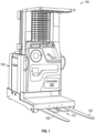
- a material handling vehicle 100 may include a power source 102, a first fork 103, a second fork 105, a controller 108, and a clamp assembly 110.
- the power source 102 can be a battery installed on the material handling vehicle 100.
- the power provided by the power source 102 can be passed through a regulated supply device to limit power draw from the clamp assembly 110 to a predetermined limit (e.g., 100 Watts).
- the power provided by the power source can also pass through various safety and control devices, such as fuses, current limiters, power suppliers, and switches.
- the clamp assembly 110 can be configured to selectively engage a load.
- the clamp assembly 110 can be configured to clamp a center wall (e.g., a center stringer) of a load.
- the clamp assembly 110 may include a housing 101 with a first arm portion 104, a second arm portion 106, a first grip arm or assembly 114, and a second grip arm or assembly 116.
- the first grip assembly 114 may be moveably or pivotally engaged with the first arm portion 104.
- the second grip assembly 116 may be pivotally engaged with the second arm portion 106.
- the first grip assembly 114 and the second grip assembly 116 may be arranged opposite each other and face one another.
- the first and second grip assemblies 114, 116 can be biased towards each other (e.g., via a spring). As best illustrated in FIG. 2 , when no outside forces are applied onto the first and second grip assemblies 114, 116, they are separated by a lateral distance, D1.
- the lateral distance D1 can define a gap between the first and second grip assemblies 114, 116 that is less than a width of a structure (e.g., a center wall) that is configured to be inserted between the first and second grip assemblies 114, 116.
- a structure e.g., a center wall
- the first and second grip assemblies can be biased towards one another (e.g., via a spring) to ensure contact between the first and second grip assemblies 114, 116 and the structure to secure and grip the structure.
- the material handling vehicle 100 can be maneuvered into position in front of a load having fork pockets within a base of the load.
- the first and second forks 103, 105 can then be inserted into fork pockets to bring the clamp assembly 110 into engagement with a center wall arranged between the fork pockets.
- the first and second grip assemblies 114, 116 can be displaced away from each other to receive the center wall due to the contact between the center wall and the first and second grip assemblies 114, 116.
- the first and second grip assemblies 114, 116 can then grip the center wall, thereby securing the load to the material handling vehicle 100.
- various other types of mechanical clamps can be used in place of the first and second grip assemblies.
- a hydraulically driven metal plate could be used to engage the load and to transfer power and/or communications to the load.
- the clamp assembly 110 can be configured to provide electrical communication between the power source 102 on the material handling vehicle 100 and a load received on the first and second forks 103, 105.
- the clamp assembly 110 can be in electrical communication with the power source 102.
- the controller 108 may also be in electrical communication with the clamp assembly 110.
- the controller 108 may be configured to selectively articulate the clamp assembly 110.
- the controller 108 can be configured to selectively rotate the first and second grip assemblies 114, 116 between a deployed position and a stowed position. In the stowed position, the first and second grip assemblies 114, 116 can be received within the first and second arm portions 104, 106 of the housing 101, respectively.
- the first and second grip assemblies 114, 116 can be manually actuated by an operator.
- the material handling vehicle 100 can have a manually operated foot pedal that, when actuated by an operator, can be configured to selectively rotate the first and second grip assemblies 114, 116 between the deployed position and the stowed position.
- an electrical switch can be mounted within an operator compartment to selectively rotate the first and second grip assemblies 114, 116 between the deployed position and the stowed position.
- the clamp assembly 110 can include one or more electrical contacts.
- the electrical contacts can be configured to transfer power to a load on the material handling vehicle 100.
- one of the first grip assembly 114 or the second grip assembly 116 can include at least one power contact.
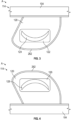
- FIG. 3 a top view of the first grip assembly 114 is shown.
- the first grip assembly114 may include a first lobe or clamping arm 120, a first mount 122, and a first power contact 124.
- the first mount 122 may be inserted into and supported by the first clamping arm 120.
- the first mount 122 may be generally flush with the first clamping arm 120.
- the first mount 122 may be constructed of an electrically insulating material (e.g., plastic, rubber, silicone, etc.).
- the first power contact 124 can be configured to engage with corresponding contacts within a base of a load to transfer power from the power source 102 to the load.
- the first power contact 124 can be coupled to the first clamping arm 120 by the first mount 122 to electrically insulate the first power contact 124 from the first clamping arm 120.
- the first power contact 124 may be inserted into and supported by the first mount 122.
- the first power contact 124 may be crescent-shaped, although other shapes are envisioned. The crescent or arcuate-shaped first power contact 124 can provide a wiping electrical contact.
- the arc-shaped electrical contacts can enable the clamp assembly 110 to engage center walls of a loads having a variety of center wall thicknesses while maintaining electrical contact between the electrical contacts (e.g., first contact 124) and a corresponding electrical contact within a base of a load.
- the arc of the electrical contacts can share a center of rotation with the rotation of the first and second grip assemblies 114, 116.
- the first power contact 124 may be constructed of an electrically conductive material (e.g., metal or carbon).
- power contacts can be over-molded into the mounts, including wire leads that may lead to or from the power contacts.
- the first power contact 124 may be in electrical communication with the power source 102 and the controller 108.
- the controller 108 can be configured to selectively energize the first power contact 124 with power from the power source 102.
- the first grip assembly 114 may also include a second mount 126 and a second power contact 128 opposite the first mount 122 and first power contact 124.
- the bottom side of the first grip assembly 114 ( FIG. 4 ) can be substantially similar to the top side ( FIG. 3 ).
- the bottom of the first grip assembly 114 can be substantially similar, include similar structures, and perform similar functions as the top of the first grip assembly 114.
- the second power contact 128 can be configured to engage with corresponding contacts within a base of a load to transfer power from the power source 102 to a load.
- the second mount 126 may be inserted into and supported by the first clamping arm 120.
- the second mount 126 may be generally flush with the first clamping arm 120.
- the second mount 126 may be constructed of the electrically insulating material and be configured to electrically isolate the second power contact 128 from the first clamping arm 120.
- the second power contact 128 may be inserted into and supported by the second mount 126.
- the second power contact 128 may be a mirror image of the first power contact 124 and thus crescent-shaped. It is anticipated that the second power contact 128 may be constructed of the electrically conductive material.
- the second power contact 128 may be in electrical communication with the power source 102 and the controller 108.
- the controller 108 may selectively energize the second power contact 128.
- the controller 108 may energize the second power contact 128 based on an input from an operator.
- the controller 108 can be configured to selectively energize the second power contact 128.
- the electrical contacts can protrude from a surface of the clamping arms.
- the electrical contacts can be arranged on opposing sides of the clamping arms.
- the first power contact 124 may be opposite the second power contact 128.
- the first power contact 124 and the second power contact 128 may extend away from the first clamping arm 120.
- the first power contact 124 and the second power contact 128 may project beyond or protrude from the first clamping arm 120.
- a switch can be included to allow an operator to selectively turn on/off the power to the first power contact 124 and the second power contact 128.
- the clamp assembly 110 can include one or more electrical contacts configured to transfer communication signals between a load on the material handling vehicle 100.
- one of the first grip assembly 114 or the second grip assembly 116 can include at least one signal contact.
- the signal contacts can be configured to engage with corresponding contacts within a base of a load to communicate information or signals to/from the material handling vehicle 100 to the load.
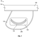
- the second grip assembly 116 may include a second lobe or clamping arm 132, a third mount 134, and a first signal contact 136.
- the third mount 134 may be inserted into and supported by the second clamping arm 132.
- the third mount 134 may be generally flush with the second clamping arm 132.
- the third mount 134 may be constructed of the electrically insulating material and be configured to electrically isolate the first signal contact 136 from the second clamping arm 132.
- the first signal contact 136 may be inserted into and supported by the third mount 134.
- the first signal contact 136 may be crescent-shaped, although other shapes are envisioned.
- the crescent or arcuate-shaped first signal contact 136 can provide a wiping electrical contact.
- the first signal contact 136 may be in electrical communication with the controller 108.
- signal contacts can be over-molded into the mounts, including wire leads that may lead to or from the signal contacts.
- the bottom side of the second grip assembly 116 ( FIG. 7 ) can be substantially similar to the top side ( FIG. 6 ).
- the bottom of the second grip assembly 116 can be substantially similar, include similar structures, and perform similar functions as the top of the second grip assembly 116.
- the second grip assembly 116 may include a fourth mount 138 and a second signal contact 140.
- the fourth mount 138 may be inserted into and supported by the second clamping arm 132.
- the fourth mount 138 may be generally flush with the second clamping arm 132.
- the fourth mount 138 may be constructed of the electrically insulating material and be configured to electrically isolate the second signal contact 140 from the second clamping arm 132.
- the second signal contact 140 may be inserted into and supported by the fourth mount 138.
- the second signal contact 140 may be a mirror image of the first signal contact 136 and thus crescent-shaped.
- the second signal contact 140 may be in electrical communication with the controller 108.
- the first signal contact 136 may be opposite the second signal contact 140.
- the first signal contact 136 and the second signal contact 140 may extend away or protrude from the second clamping arm 132. In other words, the first signal contact 136 and the second signal contact 140 may project beyond the second clamping arm 132.
- the first signal contact 136 may include a plurality of signal contacts 136A, 136B, 136C, and a plurality of insulators 146. It is anticipated that the plurality of insulators 146 are constructed of the electrically insulating material. It is also anticipated that the plurality of signal contacts 136A-136C may be constructed of the electrically conductive material. The individual insulators of the plurality of insulators 146 may be alternatingly layered between individual tracks of the plurality of signal contacts 136A-136C. Thus, the plurality of insulators 146 may electrically isolate individual tracks of the plurality of signal contacts 136A-125C from one another. Looking back to FIGS.
- the first signal contact 136 may be a mirror image of the second signal contact 140.
- the second signal contact 140 may also include a plurality of signal contacts and a plurality of insulators (140A-140C and 146, see FIG. 11 ).
- the clamp assembly 110 can include a plurality of signal contacts.
- the plurality of signal contacts can provide CAN signal communication capabilities.
- CAN communication is two way communication based on the CAN standard which uses three signal contacts (e.g., CAN High, CAN Low, Ground-Return) and a fourth signal contact (e.g., Engage).
- the "engage" signal contact can be used as a signal to indicate that a clamp assembly has engaged a load.
- the controller 108 can be configured to selectively energize one or more of the power contacts or signal contacts on the first grip assembly 114 or the second grip assembly 116 based on system checks of the material handling vehicle 100.
- the material handling vehicle 100 may be equipped with one or more sensors and the controller 108 may be in electrical communication with the sensors to perform system checks on the material handling vehicle 100.
- the controller 108 can be configured to perform an engagement system check that can include determining whether a load is correctly engaged by the forks 103, 105 or the clamp assembly 110.
- the controller 108 may apply power and make one or more attempts to communicate with the load via the power contacts or signal contacts. The power applied may be limited by a fuse or circuit breaker on the material handling vehicle 100. If the controller 108 does not receive expected responses (e.g., CAN bus messages) to the communication attempt, the system check may indicate that the load is not correctly engaged by the clamp assembly 110.
- expected responses e.g., CAN bus messages
- a disengagement system check may include determining whether a load is correctly disengaged by the clamp assembly 110.
- the controller 108 may continue to communicate with a load after the material handling vehicle 100 has attempted to disengage from the load. If communication persists (e.g., via the power or signal contacts), the system check may indicate that the load is not correctly disengaged. It should be appreciated that the controller 108 may alert an operator that the load remains engaged before the material handling vehicle 100 drives away.
- a status system check may include interrogating a load for status information (e.g., via the signal contacts).
- the controller 108 may query the load for a load identity, failure codes for the machinery on the load, and the load's status. Additionally, based on the status information, the controller 108 may instruct the load to perform one or more operations (e.g., rotate a bin or actuate a carousel).
- a loading system check may include interrogating a load for item loading information.
- the controller 108 may query sensors (e.g., bar code scanners, 2D bar codes processors, RFID chips, location detectors, etc.) mounted on the load to monitor items loaded or removed from the load. The controller 108 may alert the operator to any item count defects when the load is engaged.
- sensors e.g., bar code scanners, 2D bar codes processors, RFID chips, location detectors, etc.
- a power draw system check may include monitoring, with the controller 108, electrical power drawn by a load. It should be understood that the above-described system checks are non-limiting examples and that the controller 108 may perform any type of system check.
- clamp assembly described herein or the power and signal contacts provided thereon, could be retrofit into trucks with pre-existing pallet clamps, or the clamp assembly described herein could be a direct replacement for the pallet clamp on pallet clamp equipped material handling vehicles.
- the load assembly 152 may include a base 156 and a load 158.
- the base 156 may support the load 158.
- the base 156 can be a pallet, or be similar in shape and structure to a pallet.
- the base 156 may include a center wall 162 (e.g., a center stringer of a pallet), a top plank or wall 164, and a bottom plank or wall 166 opposite the top wall 164.
- a spacing formed between the top wall 164 and the bottom wall 166 can be divided by the center wall 162 to form fork pockets 163.
- the fork pockets 163 can be configured to receive the first and second forks 103, 105 (see FIG. 2 ) of the material handling vehicle 100.
- the base 156 can include electrical contacts configured to engage with the electrical contacts on the clamp assembly 110 to transfer power or communication signals between the power source 102 and the controller 108 to the load 158.
- the base 156 can include a plurality of electrical contacts that correspond and engage with the plurality of electrical contacts on the clamp assembly 110.
- the electrical contacts can protrude from a surface of the base 156 into a cavity formed by the fork pockets 163.
- the base 156 can include one or more electrical contacts configured to transfer power to the load 158.
- one of the top wall 164 or the bottom wall 166 can include at least one power contact configured to engage with one of the first or second power contacts 124, 128 of the clamp assembly 110.
- the base 156 can also include one or more electrical contacts configured to transfer communication signals between the controller 108 and the load 158.
- one of the top wall 164 or the bottom wall 166 can include at least one signal contact configured to engage with one of the first or second signal contacts 136, 140 of the clamp assembly 110.
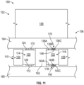
- the base 156 can include a first power pin 170, a second power pin 172, first signal pins 176, and second signal pins 178.
- the center wall 162 separates first power pin 170 and the first signal pins 173 from the second power pin 172 and the second signal pins 178. Said another way, the first power pin 170 and the first signal pins 173 are arranged within one of the fork pockets 163 and the second power pin 172 and the second signal pins 178 are arranged in the other fork pocket 163.
- the center wall 162 may be connected to the top wall 164 and the bottom wall 166 and be configured to be received within and engaged by the clamp assembly 110 (see FIG. 2 ).
- the first power pin 170 and the first signal pins 176 may extend from the top wall 164 toward the bottom wall 166.
- the first power pin 170 and/or the first signal pins 176 may be slidably engaged with the top wall 164.
- the first power pin 170 and/or the first signal pins 176 may be spring-loaded relative to the top wall 164 such that the first power pin 170 and the first signal pins 176 are biased away from the top wall 164.
- the second power pin 172 and the second signal pins 178 may extend from the bottom wall 166 toward the top wall 164.
- the second power pin 172 and the second signal pins 178 may be slidably engaged with the bottom wall 166.
- the second power pin 172 and the second signal pins 178 may be spring-loaded relative to the bottom wall 166 such that the second power pin 172 and the second signal pins 178 are biased away from the bottom wall 166.
- the center wall 162 may be arranged between the first power pin 170 and the first signal pins 176.
- the center wall 162 may be arranged between the second power pin 172 and the second signal pins 178.
- the first power pin 170, the second power pin 172, the first signal pins 176, and the second signal pins 178 may be in electrical communication with the load 158.
- the first power pin 170 and the second power pin 172 may be sized and configured to provide electrical energy to the base 156 and/or the load 158 (e.g., to support a refrigeration compressor, run a fan, illuminate a lamp, actuators, carousels, lights, etc.), from the power source 102 on the material handling vehicle 100 when the clamp assembly 110 is engaged with the center wall 162.
- the first signal pins 176 and the second signal pins 178 may be sized and configured to transmit information between the base 156 and/or the load 158 and the controller 108 on the material handling vehicle 100 when the clamp assembly 110 is engaged with the center wall 162.
- the information may include, for example, an internal temperature of the load 158, inertial movement data of base 156 and/or the load 158, location data of base 156 and/or the load 158, a time since the load 158 was opened, etc.
- the first signal pins 176 and the second signal pins 178 may be sized and spaced relative to one another to correspondingly contact one or more signal contacts among the plurality of signal contacts 140A-140C on the clamp assembly 110.
- the first arm portion 104 and the second arm portion 106 of the clamp assembly 110 may be inserted between the top wall 164 and the bottom wall 166 such that the center wall 162 may be received between the first grip assembly 114 and the second grip assembly 116.
- the controller 108 may instruct the first grip assembly 114 to pivot outwardly relative to the first arm portion 104 and the second grip assembly 116 to pivot outwardly relative to the second arm portion 106 to actuate the first and second grip assemblies 114, 116 from a stowed position to a deployed or clamped position.
- the controller 108 may selectively pivot the first grip assembly 114 relative to the first arm portion 104 and the second grip assembly 116 relative to the second arm portion 106 to grip and secure the center wall 162.
- the center wall 162 may be compressed and gripped firmly between the first clamping arm 120 and the second clamping arm 132, thereby securing the base 156, and thus the load, 158, to the material handling vehicle 100.
- the material handling vehicle 100 and the base 156 may be collectively referred to as a material handling system 190.
- the first power contact 124 may contact and slidably sweep against the first power pin 170.
- the first power contact 124 may depress the first power pin 170 into the top wall 164 and the first power contact 124 may be placed in electrical communication with the first power pin 170.
- the second power contact 128 may contact and slidably sweep against second power pin 172.
- the second power contact 128 may depress the second power pin 172 into the bottom wall 166 and the second power contact 128 may be placed in electrical communication with the second power pin 172.
- the first signal contact 136 may contact and slidably sweep against the first signal pins 176.
- the first signal contact 136 may depress the first signal pins 176 into the top wall 164 and the first signal contact 136 may be placed in electrical communication with the first signal pins 176.
- the second signal contact 140 may contact and slidably sweep against the second signal pins 178.
- the second signal contact 140 may depress the second signal pins 178 into the bottom wall 166 and the second signal contact 140 may be placed in electrical communication with the second signal pins 178.
- the controller 108 may electronically send and receive information to and from the base 156 and/or the load 158 via the first signal contact 136 and/or the second signal contact 140.
- the load assembly 252 may be an alternative arrangement of the load assembly 152 of FIGS. 10 and 11 .
- the second embodiment of the load assembly 252 can be substantially similar to the load assembly 152 of FIGS. 10 and 11 , with the exception that the power and signal contacts are located along the center wall 162 as opposed to the top and bottom walls 164, 166.
- the load assembly 252 may include the base 156 and the load 158.
- the base 156 may support the load 158.
- the base 156 may include the center wall 162, the top wall 164, the bottom wall 166, the first power pin 170, the second power pin 172, the first signal pins 176, and the second signal pins 178.
- the center wall 162 may be connected between the top wall 164 and the bottom wall 166.
- any of the first power pin 170, the second power pin 172, the first signal pins 176, and/or the second signal pins 178 may extend outwardly from the center wall 162 between the top wall 164 and the bottom wall 166, perpendicular to the center wall 162.
- Any of the first power pin 170, the second power pin 172, the first signal pins 176, and the second signal pins 178 may be slidably engaged with and spring-loaded relative to the center wall 162.
- the first power pin 170 and the second power pin 172 may extend oppositely from one another.
- the first signal pins 176 and the second signal pins 178 may extend oppositely from one another.
- the center wall 162 may be between the first power pin 170 and the second power pin 172.
- the center wall 162 may be between the first signal pins 176 and the second signal pins 178.
- the first power pin 170, the second power pin 172, the first signal pins 176, and the second signal pins 178 may be in electrical communication with the load 158.
- the first power pin 170 and the second power pin 172 may be sized and configured to provide electrical energy to the base 156 and/or the load 158 (e.g., to support a refrigeration compressor, run a fan, illuminate a lamp, etc.), from the power source 102.
- the clamp assembly 110 can be altered or arranged in an alternative embodiment in order for the power and signal pins to engage with the load assembly 252 of FIGS 10 and 11 .
- the first clamping arm 120 may include a first side 262 facing towards the second clamping arm 132.
- the first clamping arm 120 may include a third power contact and a third signal contact mounted along the first side 262 (not shown).
- the third signal contact may include a plurality of signal contacts and a plurality of insulators. It is anticipated that the third power contact and the third signal contact may be constructed of the electrically conductive material and mounted in the electrically insulating material.
- the third power contact may be in electrical communication with the power source 102 and the controller 108.
- the controller 108 may selectively energize the third power contact.
- the third signal contact may be in electrical communication with the controller 108.
- the third power contact and the third signal contact may extend laterally away from the first clamping arm 120. In other words, the third power contact and the third signal contact may project beyond the first side 262.
- a switch can be included to allow the operator to turn on the power to third power contact and the third signal contact.
- the first clamping arm 120 may operate with the load assembly 252 of FIG. 12 via the third power contact and the third signal contact. In operation, the third power contact may contact and compress the first power pin 170 and the third signal contact may contact and compress the first signal pins 176.
- the second clamping arm 132 may include a second side 266 facing towards the first clamping arm 120 and opposite the first side 262. Additionally or alternatively, the second clamping arm 132 may include a fourth power contact and a fourth signal contact mounted along the second side 266 (not shown).
- the fourth signal contact may include a plurality of tracks and a plurality of insulators. It is anticipated that the fourth power contact and the fourth signal contact may be constructed of the electrically conductive material and mounted in the electrically insulating material.
- the fourth power contact may be in electrical communication with the power source 102 and the controller 108.
- the controller 108 may selectively energize the fourth power contact.
- the fourth signal contact may be in electrical communication with the controller 108.
- the fourth power contact and the fourth signal contact may extend laterally away from the second clamping arm 132. In other words, the fourth power contact and the fourth signal contact may project beyond the second side 266.
- the switch may allow the operator to turn on the power to fourth power contact and the fourth signal contact.
- the second clamping arm 132 may operate with the load assembly 252 of FIG. 12 via the fourth power contact and the fourth signal contact. For example, in operation, the fourth power contact may contact and compress the second power pin 172. Additionally, in operation, the fourth signal contact may contact and compress the second signal pins 178.
- the clamp assembly 110 can enable a material handling vehicle to provide power and/or communication signals to a load 158 (see FIG. 11 )
- the load 158 cab be a load-supporting container, a material sorting system, etc.
- the load can have a base configured to receive the power and/or communication signals from the material handling vehicle.
- the load can be embodied in various ways.
- a material sorting system can be coupled to a base that can be engaged by a material handling vehicle.
- the goods may be retrieved from shelving racks, and the like, and sorted prior to shipping out to a purchasing consumer.
- conventional "put walls” and order-picking carts are typically used.
- these conventional "put walls” are stationary and order-picking carts are manually pushed around by the worker.
- conventional order-picking typically consists of a worker placing items onto a pallet or into a cart.
- the present disclosure provides a material sorting system that can be configured to travel or be moved within a warehouse to a location of a stored good.
- the material sorting system can be configured to operatively attach to a material handling vehicle.
- the operative attachment can include an electrical attachment, such as the clamp assembly previously described herein (See FIG. 1 ), with electrical power and/or electronic communication contacts described above.
- the material sorting system can be driven with an internal drive system and can be configured to be driven autonomously or by an operator.
- the material sorting system can indicate a predetermined location within the material sorting system for the good to be stored.
- the material sorting system can be a carousel with storage racks or containers movable along a track of the carousel.
- the track can be vertically oriented relative to the ground.
- other track orientations are contemplated, such as horizontal or rotary tracks.
- order-picking can be improved when using the material sorting system described herein.
- the systems and methods described herein can increase the put density. This can allow an operator or worker to fulfill more orders.
- Ergonomics can also be improved, for example, as a carousel system can position the appropriate tote or box in an area, height, or position that is convenient for the worker.
- a material sorting system 310 can be coupled to the base 156 (see FIGS. 10-12 ).
- the material sorting system 310 can include a carousel assembly 318.
- the base 156 can include a drive system 312.
- the drive system 312 can operate wheels 314 to move the base 356 and carousel assembly 318 in a forward and a backward direction along the Z-axis as provided on FIG. 13 .
- the drive system 312 can be configured to rotate the wheels 314 in opposite directions to rotate the base 156 about the Y-axis, for example, similar to tank-steering.
- the drive system 312 can be powered by an onboard power supply (e.g., one or more batteries).
- Caster wheels 322 can be attached to the base 156, shown here at corners 324 of the rectangular-shaped base 156, and can provide additional support and stability for the material sorting system 310 when the base 156 is not being carried by a material handling vehicle.
- the base 156 can be sized and shaped similarly to a pallet and can be configured to interface with a material handling vehicle.
- the base 156 can have a center wall 162 and openings or fork pockets 163 to each side of the center wall 162.
- the material handling vehicle 100 e.g., a high-lift forklift
- the material handling vehicle 100 can include a pair of forks (not shown, see FIG. 1 ) configured to be received within the fork pockets 163 of the base 156.
- the fork pockets 163 in the base 156 can enable a material handling vehicle to carry and move the material sorting system 310.
- the configuration of the material handling vehicle engaged with the base 156 can be referred to as a material handling system 190.
- the base 156 can take other shapes and configurations.
- the base 156 can be substantially circular.
- a circular base may be advantageous and provide better maneuverability.
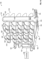
- the carousel assembly 318 can be a vertical carousel and include one or more storage units configured to be movable relative to the base 156 to receive goods picked by an order-picker.
- the carousel assembly includes a plurality of storage units 320 movable along tracks 326 on a set of opposing stalks 328 that are coupled to the base 156.
- the carousel assembly 318 can include an actuation mechanism 327 operatively coupled to the tracks 326 and configured to move the plurality of storage units 320 along the tracks 326.
- the actuation mechanism 327 can include an electric motor configured to drive a belt, chain, or gear drive system (not shown) configured to move the plurality of storage units 320 along the tracks 326.
- the actuation mechanism 327 may include a linear actuator or any other mechanical, electrical, or hydraulic mechanism that is capable of moving the plurality of storage units 320.
- the stalks 328 can be coupled to and extend upward from the base 156. In the illustrated embodiment, the stalks 328 can be arranged substantially over the wheels 314 and extend vertically along the Y-axis.
- the location of the stalks 328 over the wheels 314 can distribute the weight of the carousel assembly 318 more directly onto the wheels 314 in a direction substantially perpendicular to the ground (e.g., the direction of the y-axis). This arrangement can enhance stability and control of the material sorting system 310.
- the tracks 326 can provide a continuous path for the storage units 320 to traverse along the stalks 328.
- the stalks 328 can further include indicators 330 at the distinct stop locations along the stalks 328.
- the indicators 330 can be lights or other identifying indicia and can provide information to an operator 340.
- the indicators 330 can be multi-color lights. For example, during operation, the indicators 330 can be normally illuminated red lights.
- each of the plurality of storage bins 320 can include an indicator to designate the placement of a good within a specific storage unit 320.
- each of the plurality of storage bins 320 can include a smart barcode tag. The smart barcode tag can integrate with a controller or warehouse management system to designate the placement of a good within a specific storage unit 320.
- FIG. 14 illustrates an example movement of the storage units 320 along the stalks 328 (as shown by arrows 329).
- the storage units 320 can be configured to be accessible along the entire length of the tracks 326.
- the actuation mechanism 327 can be configured to move the storage units 320 nearest the operator 340 in an upward direction relative to the base 156. It should understood that the direction of motion can be reversed to move the storage units 320 nearest the operator 340 in a downward direction relative to the base 156 as well (e.g., the motor of an actuation mechanism can be reversed).
- the movement of the storage units 320 can be automated (i.e., programmed to locate a specific storage unit 320 at a specific distinct stop location depending on an input, remote or local), mechanically driven and controlled by an operator using a switch or control panel, or manually moved around the tracks 326 by an operator.
- the carousel assembly 318 can be powered by the power supply 102 on the material handling vehicle 100 via electrical contacts on a clamp assembly, which can also provide power to the drive system 312 and/or the actuation mechanism 327.
- the carousel assembly 318 can include a separate power supply (not shown).
- the base 156 can include one or more electrical contacts configured to receive power or communication signals from corresponding electrical contacts on a clamp assembly 110.
- the clamp assembly 110 can be configured to deliver power and communication signals from the material handling vehicle 100, such as the material handling vehicle illustrated in FIG. 14 , to the material sorting system 310 illustrated in FIG. 14 via the one or more electrical contacts within the base 156.
- the clamp assembly 110 can be positioned between a pair of forks on the material handling vehicle and can include a first grip arm or assembly 114, and a second grip arm or assembly 116.
- the first and second grip assemblies 114, 116 can include at least one power contact (e.g., first and second power contacts 124, 128).
- the first and second grip assemblies 114, 116 can include at least one signal contact (e.g., first and second signal contacts 136, 140). Additional power and signal contacts or alternative arrangements of the power and signal contacts are contemplated (see, e.g., FIG. 12 ).
- the first and second grip assemblies 114, 116 can be configured to selectively and removably engage both sides of the base 156 via the center wall 162 when the pair of forks are received within the fork pockets 163.
- electrical contacts can be provided in the base 156 within either or both of the fork pockets 163 and can be configured to electrically contact with either or both of the power and signal contacts (e.g., first and second power contacts 124, 128 and/or first and second signal contacts 136, 140).
- the base 156 can include a first power pin 170, a second power pin 182, first signal pins 176, and second signal pins 178 within the fork pockets 163 and adjacent to the center wall 162.
- electrical power and communications can be transferred between the material handling vehicle 100 and the material sorting system 310.
- the carousel assembly 318 can be in electrical communication with one or more of the first and second power pins 170, 182 and first and second signal pins 176, 178.
- the carousel assembly 318 can receive power from the first and second power pins 170, 182 when power is provided from an external source.
- the carousel assembly 318 can be powered by the power supply 102 on the material handling vehicle 100 via the first and second power pins 170, 182.
- the carousel assembly 318 can also receive communication and/or command signals from the first and second signal pins 176, 178.
- the carousel assembly 318 can receive communication and/or command signals from the controller 108 on the material handling vehicle 100 via the first and second signal pins 176, 178.
- the actuation mechanism 327 of the carousel assembly can be in electrical communication with one or more of the first and second power pins 170, 182 and first and second signal pins 176, 178.
- the actuation mechanism 327 can receive power from the power source 102 on the material handling vehicle via the first and second power pins 170, 182.
- the actuation mechanism 327 can also receive communication and/or command signals from the first and second signal pins 176, 178.
- the actuation mechanism 327 can receive communication signals from the controller 108 on the material handling vehicle to issue actuation commands.
- the actuation commands can include positioning the plurality of storage units 320 in the distinct stop locations along the tracks 326 of the carousel assembly 318.
- the indicators 330 of the carousel assembly can be in electrical communication with one or more of the first and second power pins 170, 182 and first and second signal pins 176, 178.
- the indicators 330 can receive power from the power source 102 on the material handling vehicle via the first and second power pins 170, 182 to turn on/off the indicator lights.
- the indicators 330 can also receive communication and/or command signals from the first and second signal pins.
- the indicators 330 can receive communication signals from the controller 108 on the material handling vehicle to issue illumination commands (e.g., to change colors of the indicators 330, etc.).
- the controller 108 on the material handling vehicle 100 can actuate and control the material sorting system 310.
- the material handling system 190 including the material handling vehicle 100 and the material sorting system 310, can be utilized with a warehouse management system (not shown).
- the warehouse management system can generate and issue a pick command to the operator 340 of the material handling vehicle 100 (e.g., via a personal or handheld device) and simultaneously to the controller 108 of the material handling vehicle 100.
- This pick command can be transmitted to the material sorting system 310 via the electrical contacts within the clamp assembly 110 (see FIG. 11 ), when the clamp assembly 110 is engaged with the base 156 and in electrical communication with the electrical contacts within the base 156.
- the controller can trigger the actuation mechanism 327 on the material sorting system 310 to position the appropriate storage unit 320 to an ergonomic put position for the operator 340.
- the controller 108 can communicate a signal to illuminate the indicator light 330 adjacent to the storage unit 320 to indicate to the operator which storage unit 320 to put the picked goods or item in.
- the operator 340 can transport the material sorting system 310 to an area within the warehouse via the material handling vehicle 100.
- the material sorting system 310 can drive autonomously between areas within a warehouse.
- the carousel assembly 318 can include an onboard controller (not shown). The onboard controller can receive the pick commands from the warehouse management system and the onboard controller can trigger the actuation mechanism 327 on the material sorting system 310 to position the appropriate storage unit 320 to an ergonomic put position for the operator 340.
- the carousel assembly 318 can include an electrical switch in electrical communication with the actuation mechanism 327.
- the electrical switch can be actuated by an operator of the material handling vehicle to trigger the actuation mechanism 327 on the material sorting system 310 to position the appropriate storage unit 320 to a desired put position for the operator.
- the carousel assembly 318 can include hand crank or flywheel assembly mechanically coupled to the actuation mechanism 327. The hand crank can be actuated by an operator of the material handling vehicle to manually actuate the actuation mechanism 327 on the material sorting system 310 to position the appropriate storage unit 320 to a desired put position for the operator
- FIG. 15 illustrates another embodiment of a material sorting system 410.
- the material sorting system 410 is similar to the material sorting system 310 described above and similar numbering in the 400 series is used for the material sorting system 410.
- the material sorting system 410 includes a carousel assembly 418.
- the base 156 can include caster wheels 422 at corners 424 and the carousel assembly can include stalks 428 with indicators 430 and tracks 426 along which storage units 420 can move.
- the material sorting system 410 may also be configured to be electrically coupled to a material handling vehicle 100 illustrated here in FIG. 15 as a low-lift forklift with forks 103, 105 extending through openings or fork pockets 163 in the base 156.
- the electrical coupling can provide electrical power and communication between the material handling vehicle 100 and the material sorting system 410.
- the material sorting systems 310, 410 differ from each other.
- the carousel assembly 418 can be rotated 90 degrees on the base 156 with respect to the orientation of the carousel assembly 318 on the base 156 of the material sorting system 310.
- This arrangement can provide access to the storage units from the sides of the material handling vehicle 100.
- This arrangement can also allow for the combination of more than one material sorting system per material handling vehicle.
- they can be modularly stacked side by side on the forks of the material handling vehicle.
- multiple clamp assemblies can be integrated between the forks to accommodate the multiple material sorting systems.
- the adjacent material sorting systems can be electrically coupled together (e.g., via cables, and the like).
- FIG. 16 another embodiment of a material sorting system 510 is shown.
- the material sorting system 510 is similar to the material sorting systems 410 described above and similar numbering in the 500 series is used for the material sorting system 510.
- the material sorting system 510 includes a carousel assembly 518 with stalks 528 with indicators 530 and tracks 526 along which storage units 520 can move.
- the material sorting system 510 can be configured to be electrically coupled to a material handling vehicle 100, shown as the low-lift forklift illustrated in FIG. 16 . In some aspects, however, the material sorting systems 410, 510 can differ.
- the base 156 can be a stationary base without powered or driven wheels incorporated therein.
- the base 156 can have removable caster wheels or can be provided without caster wheels.
- the material sorting system 510 can, for example, be located at the end of an aisle and positioned for a vehicle (e.g., the material handling vehicle 100) to engage therewith and move the material sorting system 510 as required. Additionally or alternatively, the material sorting system 510 can be placed on top of an Automated Guided Vehicle (AGV) that can move the material sorting system 510 from location to location. As previously described herein, the material sorting system 510 can be powered by the onboard power supply 102 via the clamp assembly (not shown) on the material handling vehicle.
- AGV Automated Guided Vehicle
- FIG. 17 another embodiment of a material sorting system 610 is shown.
- the material sorting system 610 is similar to the material sorting systems 510 described above and similar numbering in the 600 series is used for the material sorting system 610.
- the material sorting system 610 includes a carousel assembly 618 with a plurality of storage units 620.
- the material sorting system 610 can be configured to be electrically coupled to a material handling vehicle 100. In some aspects, however, the material sorting systems 510, 610 can differ.
- the material sorting system 610 can be a horizontal or rotary carousel and include a single central stalk 628 extending vertically from the base 156.
- the carousel assembly 618 can be configured to rotate about the base 156 around an axis generally defined by the stalk 628.
- the material sorting system 610 can include an external cage or structure 644 at least partially surrounding the carousel assembly 618.
- the material sorting system 610 can be powered by the onboard power supply via the clamp assembly (not shown) on the material handling vehicle.
- the material sorting system 710 is similar to the material sorting systems 310 and 410 described above and similar numbering in the 700 series is used for the material sorting system 710.
- the material sorting system 710 includes a carousel assembly 718.
- the base 156 can assembly can include stalks 728 extending from the base 156 and tracks 726 along which storage units 720 can move.
- An actuation mechanism 727 can be configured to move the storage units 720 along the tracks 726.
- the material sorting system 710 may also be configured to be electrically coupled to a material handling vehicle 100 via a clamp assembly 110 (see FIG.
- the electrical coupling can provide electrical power and communication between the material handling vehicle 100 and the material sorting system 710.
- the material sorting systems 310, 710 differ from each other.
- lateral side of the stalks 728 on the carousel assembly 718 can include openings 746 to allow the storage units 720 to be loaded/unloaded from the lateral sides of the carousel assembly 718.
- the storage units 720 can include a conveyor track 748 with a plurality of rollers 750 along a base of each of the storage units 720.
- the rollers 750 may be powered and activated (e.g., instructed to roll in a first direction or a second direction) by the connection provided between the base 156 and the clamp assembly 110.
- the openings 746 in the stalks 728, along with the conveyor track 748 in the storage unit 720, can allow loading and unloading operations to be conducted from external conveyor systems 760 within a warehouse environment. That is, the material handling vehicle 100 may be driven up to a conveyor system 760 and lateral sides of the material sorting system 710 can be aligned with the conveyor system 760 such that a storage unit 720 on the carousel assembly 718 is adjacent to an end of the conveyor system 760. Goods can then be loaded onto the storage unit 720, or unloaded from the storage unit 720.
- the conveyor track 748 and/or rollers 750 can be rotated via a conveyor actuation mechanism (not shown).
- the conveyor actuation mechanism can be in electrical communication with the electrical contacts within the base 156 to receive power and communication signals.
- a material sorting system comprising: a carousel assembly including:
- a material sorting system of aspect A or B further comprising a drive system coupled to the base.
- a material sorting system of aspect D wherein the set of stalks include indicator lights adjacent to the stop locations for the plurality of storage units and configured to indicate a placement position for picked goods.
- a material sorting system 310 adapted to engage a material handling vehicle 100, the material sorting system 310 comprising:
- a material sorting system 310 of aspect F wherein the at least one electrical contact protrudes from a surface of the base 163 into a cavity formed by the fork pockets 163.
- a material sorting system 310 of the aspect I wherein the actuation mechanism 327 is configured to move the plurality of storage units 320 between stop locations along the movable track 326.
- a material sorting system 310 of aspect J wherein the set of stalks 328 include indicator lights 330 adjacent to the stop locations for the plurality of storage units 320 and configured to indicate a placement position for picked goods.
- a material sorting system 310 comprising:
- a material sorting system 310 aspect L or M wherein the at least one electrical contact protrudes into a cavity formed by the pair of fork pockets 163.
- a material sorting system 310 of aspect L wherein the electrical contact is a first power contact 124 extending from the top wall 164 of the base 156 towards the bottom wall 166.
- a material sorting system 310 of aspect Q wherein the base 156 further includes a second power contact 128 extending from the bottom wall 166 and opposite the first power contact 124.
- a material sorting system 310 of aspect S wherein the first power contact 124 and the first signal contact 136 are arranged within one fork pocket of the pair of fork pockets 163; and wherein the second power contact 128 and the second signal contact 140 are arranged within the other fork pocket of the pair of fork pockets 163.
Landscapes
- Engineering & Computer Science (AREA)
- Transportation (AREA)
- Structural Engineering (AREA)
- Mechanical Engineering (AREA)
- Life Sciences & Earth Sciences (AREA)
- Civil Engineering (AREA)
- Geology (AREA)
- Combustion & Propulsion (AREA)
- Chemical & Material Sciences (AREA)
- Power Engineering (AREA)
- Sustainable Development (AREA)
- Sustainable Energy (AREA)
- Forklifts And Lifting Vehicles (AREA)
- Warehouses Or Storage Devices (AREA)
- Handcart (AREA)
- Charge And Discharge Circuits For Batteries Or The Like (AREA)
Abstract
Description
- The present application is based on and claims priority to
United States Provisional Patent Application No. 62/927,278, filed on October 29, 2019 United States Provisional Patent Application No. 62/992,548, filed on March 20, 2020 - Not Applicable.
- Typically, a warehouse may include numerous material handling vehicles performing individual tasks simultaneously and storage bins/shelves for organizing goods stored in the warehouse. Conventionally, material handling vehicles have been used to retrieve, transport, and place various types of loads.
- According to some aspects, the present disclosure provides a material handling vehicle configured to receive a load. The material handling vehicle can include a pair of forks and a clamp assembly arranged between the pair of forks. The clamp assembly can include a housing, a first grip arm protruding from the housing and moveably received by the housing, and a second grip arm protruding from the housing and moveably received by the housing. The second grip arm can be laterally opposite the first grip arm. At least one of the first grip arm or the second grip arm can include an electrical contact configured to transfer power or a communication signal.
- According to some aspects, the present disclosure provides a material handling vehicle configured to receive a load. The material handling vehicle can include a pair of forks and a clamp assembly arranged between the pair of forks. The clamp assembly can include a housing, a first grip arm pivotally coupled to the housing, and a second grip arm pivotally coupled to the housing. The second grip arm can be laterally opposite to the first grip arm. An electrically conductive material can protrude from a surface of one of the first or second grip arms to form an electrical contact configured to transfer power or a communication signal.
- According to some aspects, the present disclosure provides a material handling vehicle adapted to engage a load. The material handling vehicle can include a pair of forks and a clamp assembly arranged between the pair of forks. The clamp assembly can be configured to secure the load to the material handling vehicle when the pair of forks engage a base of the load. The clamp assembly can include a housing, a first grip arm pivotally coupled to the housing, and a second grip arm pivotally coupled to the housing. The second grip arm can be laterally opposite to the first grip arm. The first and second grip arms can be separated by a gap configured to receive a wall within the base of the load. The clamp assembly can also include at least one electrical contact that can protrude from at least one of the first or second grip arms. The at least one electrical contact can be configured to engage with a corresponding electrical contact within the base of the load to transfer power or a communication signal between the material handling vehicle and the load.
- According to some aspects, the present disclosure provides a material sorting system adapted to engage a material handling vehicle. The material sorting system includes a base including fork pockets adapted to receive a pair of forks from the material handling vehicle, and a carousel assembly coupled to the base. The carousel assembly includes a plurality of storage units and an actuation mechanism configured to move the plurality of storage units relative to the base. The material sorting system further includes at least one electrical contact within the base and in electrical communication with the carousel assembly. The at least one electrical contact being adapted to engage with a corresponding electrical contact on a clamp assembly of the material handling vehicle to transfer power or a communication signal between the material handling vehicle and the carousel assembly.
- According to some aspects, the present disclosure provides a material sorting system that includes a base. The base includes a pair of fork pockets adapted to receive a pair of forks from a material handling vehicle, a top wall, a bottom wall spaced apart from the top wall, and a center wall arranged between the top wall and the bottom wall and dividing the pair of fork pockets. The material sorting system further includes a carousel assembly coupled to the base and having a plurality of storage units and at least one electrical contact within the base and in electrical communication with the carousel assembly. The at least one electrical contact being adapted to transfer power or a communication signal between the material handling vehicle and the carousel assembly.
- According to some aspects, the present disclosure provides a material sorting system that includes a carousel assembly. The carousel assembly includes a plurality of storage units and an actuation mechanism configured to move the plurality of storage units relative to the base. The material sorting system further includes an electrical contact in electrical communication with the actuation mechanism. The electrical contact being adapted to engage with a corresponding electrical contact on a material handling vehicle to transfer power or a communication signal between the material handling vehicle and the carousel assembly.
- The foregoing and other aspects and advantages of the disclosure will appear from the following description. In the description, reference is made to the accompanying drawings which form a part hereof, and in which there is shown by way of illustration a preferred configuration of the disclosure. Such configuration does not necessarily represent the full scope of the disclosure, however, and reference is made therefore to the claims and herein for interpreting the scope of the disclosure.
- The invention will be better understood and features, aspects and advantages other than those set forth above will become apparent when consideration is given to the following detailed description thereof. Such detailed description makes reference to the following drawings.
-
FIG. 1 illustrates an exemplary material handling vehicle incorporating a clamp assembly according to one aspect of the present disclosure. -
FIG. 2 is a top view of the material handling vehicle ofFig. 1 . -
FIG. 3 is a top view of a first grip assembly of the material handling vehicle taken from region A ofFIG. 2 . -
FIG. 4 is a bottom view of the first grip assembly. -
FIG. 5 is a side view of the first grip assembly. -
FIG. 6 is a top view of a second grip assembly of the example material handling vehicle taken from region B ofFIG. 2 . -
FIG. 7 is a bottom view of the second grip assembly. -
FIG. 8 is a side view of the first grip assembly. -
FIG. 9 is a top view of a first communication contact of the second grip assembly. -
FIG. 10 is a partial side view of a load with a base according to one aspect of the present disclosure. -
FIG. 11 is a partial side view of a clamp assembly of the material handling vehicle engaged with the base of the load. -
FIG. 12 is a partial side view of a second embodiment of a load. -
FIG. 13 is a perspective view of a material sorting system according to one aspect of the present disclosure; -
FIG. 14 is a perspective view of the material sorting system ofFIG. 1 operatively connected to the material handling vehicle ofFIG. 2 ; -
FIG. 15 is a perspective view of a set of material sorting systems according to another aspect of the present disclosure, with the set of material sorting systems operatively connected to a material handling vehicle; and -
FIG. 16 is a perspective view of another set of material sorting systems according to another aspect of the present disclosure. -
FIG. 17 is a perspective view of yet another material sorting system according to another aspect of the present disclosure. -
FIG. 18 is a perspective view of yet another material sorting system according to another aspect of the present disclosure. -
FIG. 19 is a partial perspective view of the material sorting system ofFIG. 18 aligned with a conveyor system. - Before any aspects of the present disclosure are explained in detail, it is to be understood that the present disclosure is not limited in its application to the details of construction and the arrangement of components set forth in the following description or illustrated in the following drawings. The present disclosure is capable of other configurations and of being practiced or of being carried out in various ways. Also, it is to be understood that the phraseology and terminology used herein is for the purpose of description and should not be regarded as limiting. The use of "including," "comprising," or "having" and variations thereof herein is meant to encompass the items listed thereafter and equivalents thereof as well as additional items. Unless specified or limited otherwise, the terms "mounted," "connected," "supported," and "coupled" and variations thereof are used broadly and encompass both direct and indirect mountings, connections, supports, and couplings. Further, "connected" and "coupled" are not restricted to physical or mechanical connections or couplings.
- The following discussion is presented to enable a person skilled in the art to make and use aspects of the present disclosure. Various modifications to the illustrated configurations will be readily apparent to those skilled in the art, and the generic principles herein can be applied to other configurations and applications without departing from aspects of the present disclosure. Thus, aspects of the present disclosure are not intended to be limited to configurations shown, but are to be accorded the widest scope consistent with the principles and features disclosed herein. The following detailed description is to be read with reference to the figures, in which like elements in different figures have like reference numerals. The figures, which are not necessarily to scale, depict selected configurations and are not intended to limit the scope of the present disclosure. Skilled artisans will recognize the non-limiting examples provided herein have many useful alternatives and fall within the scope of the present disclosure.
- Material handling vehicles are designed in a variety of configurations to perform a variety of tasks. The present disclosure is not intended to be limited to any specific material handling vehicle, and the systems described herein can also be provided with various other types of material handling vehicle configurations, including for example, pallet trucks (e.g., pallet jacks, "tuggers", and the like), orderpickers, SWING REACH® vehicles, and any other lift or pallet carrying vehicles. The various systems and methods disclosed herein are suitable for any of driver controlled, pedestrian controlled, remotely controlled, and autonomously controlled material handling vehicles.
- Material handling vehicles can be used for carrying loads, such as pallets, loads with pallet-like bases, specialty carts, or racks. However, conventional material handling vehicles are unable to transfer power to these loads and the loads themselves are not configured to receive power from a material handling vehicle. Additionally, conventional material handling vehicles are unable to readily exchange information between the material handling vehicle and the load. It can be beneficial to be able to provide power to the load, for example, to be able to power accessories, carts, or other equipment the material handling vehicle is carrying and to transfer information between the load and the material handling vehicle. Some conventional methods of transferring power or information between a material handling vehicle and a load have been accomplished by the installation of cabled connections.
- Systems or methods of the present disclosure provide power and/or communications for the loads carried by a material handling vehicle. As used herein, a load can be defined by any structure that is configured to be engaged with, carried by, moved, or transported by a material handling vehicle. For example, a load may include one or more fork pockets configured to receive forks of a material handling vehicle. The fork pockets can be separated by a center wall that can be engaged by a clamp on the material handling vehicle. The present disclosure describes a clamp assembly that can make the transfer of power and information available between a material handling vehicle and a load. Specifically, the clamp assembly can be incorporated into or between the forks on a material handling vehicle, such as a pallet clamp, for example. In some cases, loads can have a center wall within a base of the load (e.g., a center stringer of a pallet) and the clamp assembly can selectively engage with the center wall to secure the load to the material handling vehicle.
- The clamp assembly can have electrical contacts in the form of electrical power and/or electronic communication contacts. For example, in instances when the clamp assembly is engaged with a load, the material handling vehicle may provide power and/or electronically communicate with the load. As used herein, an electrical contact can be defined as a structure at least partially formed from an electrically conductive material that can be configured to transmit electrical power or communication signals.
- Referring to
FIGS. 1-2 , amaterial handling vehicle 100 may include apower source 102, afirst fork 103, asecond fork 105, acontroller 108, and aclamp assembly 110. Thepower source 102 can be a battery installed on thematerial handling vehicle 100. The power provided by thepower source 102 can be passed through a regulated supply device to limit power draw from theclamp assembly 110 to a predetermined limit (e.g., 100 Watts). The power provided by the power source can also pass through various safety and control devices, such as fuses, current limiters, power suppliers, and switches. - The
clamp assembly 110 can be configured to selectively engage a load. For example, theclamp assembly 110 can be configured to clamp a center wall (e.g., a center stringer) of a load. Theclamp assembly 110 may include ahousing 101 with afirst arm portion 104, asecond arm portion 106, a first grip arm orassembly 114, and a second grip arm orassembly 116. Thefirst grip assembly 114 may be moveably or pivotally engaged with thefirst arm portion 104. Thesecond grip assembly 116 may be pivotally engaged with thesecond arm portion 106. Thefirst grip assembly 114 and thesecond grip assembly 116 may be arranged opposite each other and face one another. - In some embodiments, the first and
second grip assemblies FIG. 2 , when no outside forces are applied onto the first andsecond grip assemblies second grip assemblies second grip assemblies second grip assemblies second grip assemblies material handling vehicle 100 can be maneuvered into position in front of a load having fork pockets within a base of the load. The first andsecond forks clamp assembly 110 into engagement with a center wall arranged between the fork pockets. Upon engagement with the center wall, the first andsecond grip assemblies second grip assemblies second grip assemblies material handling vehicle 100. In some embodiments, various other types of mechanical clamps can be used in place of the first and second grip assemblies. For example, a hydraulically driven metal plate could be used to engage the load and to transfer power and/or communications to the load. - The
clamp assembly 110 can be configured to provide electrical communication between thepower source 102 on thematerial handling vehicle 100 and a load received on the first andsecond forks clamp assembly 110 can be in electrical communication with thepower source 102. Thecontroller 108 may also be in electrical communication with theclamp assembly 110. In some embodiments, thecontroller 108 may be configured to selectively articulate theclamp assembly 110. For example, thecontroller 108 can be configured to selectively rotate the first andsecond grip assemblies second grip assemblies second arm portions housing 101, respectively. - In some embodiments, the first and
second grip assemblies material handling vehicle 100 can have a manually operated foot pedal that, when actuated by an operator, can be configured to selectively rotate the first andsecond grip assemblies second grip assemblies - The
clamp assembly 110 can include one or more electrical contacts. The electrical contacts can be configured to transfer power to a load on thematerial handling vehicle 100. For example, one of thefirst grip assembly 114 or thesecond grip assembly 116 can include at least one power contact. Turning toFIG. 3 , a top view of thefirst grip assembly 114 is shown. The first grip assembly114 may include a first lobe or clampingarm 120, afirst mount 122, and afirst power contact 124. Thefirst mount 122 may be inserted into and supported by thefirst clamping arm 120. Thefirst mount 122 may be generally flush with thefirst clamping arm 120. Thefirst mount 122 may be constructed of an electrically insulating material (e.g., plastic, rubber, silicone, etc.). - The
first power contact 124 can be configured to engage with corresponding contacts within a base of a load to transfer power from thepower source 102 to the load. Thefirst power contact 124 can be coupled to thefirst clamping arm 120 by thefirst mount 122 to electrically insulate thefirst power contact 124 from thefirst clamping arm 120. Thefirst power contact 124 may be inserted into and supported by thefirst mount 122. In some embodiments, thefirst power contact 124 may be crescent-shaped, although other shapes are envisioned. The crescent or arcuate-shapedfirst power contact 124 can provide a wiping electrical contact. In the illustrated embodiment, the arc-shaped electrical contacts can enable theclamp assembly 110 to engage center walls of a loads having a variety of center wall thicknesses while maintaining electrical contact between the electrical contacts (e.g., first contact 124) and a corresponding electrical contact within a base of a load. In some embodiments, the arc of the electrical contacts can share a center of rotation with the rotation of the first andsecond grip assemblies first power contact 124 may be constructed of an electrically conductive material (e.g., metal or carbon). In some embodiments, power contacts can be over-molded into the mounts, including wire leads that may lead to or from the power contacts. Thefirst power contact 124 may be in electrical communication with thepower source 102 and thecontroller 108. Thecontroller 108 can be configured to selectively energize thefirst power contact 124 with power from thepower source 102. - With reference to
FIG. 4 , a bottom view of thefirst grip assembly 114 is shown. Thefirst grip assembly 114 may also include asecond mount 126 and asecond power contact 128 opposite thefirst mount 122 andfirst power contact 124. In the illustrated embodiment, the bottom side of the first grip assembly 114 (FIG. 4 ) can be substantially similar to the top side (FIG. 3 ). Unless otherwise stated in the description below or illustrated in the figures, it is to be understood that the bottom of thefirst grip assembly 114 can be substantially similar, include similar structures, and perform similar functions as the top of thefirst grip assembly 114. For example, thesecond power contact 128 can be configured to engage with corresponding contacts within a base of a load to transfer power from thepower source 102 to a load. Thesecond mount 126 may be inserted into and supported by thefirst clamping arm 120. Thesecond mount 126 may be generally flush with thefirst clamping arm 120. Thesecond mount 126 may be constructed of the electrically insulating material and be configured to electrically isolate thesecond power contact 128 from thefirst clamping arm 120. Thesecond power contact 128 may be inserted into and supported by thesecond mount 126. In some embodiments, thesecond power contact 128 may be a mirror image of thefirst power contact 124 and thus crescent-shaped. It is anticipated that thesecond power contact 128 may be constructed of the electrically conductive material. Thesecond power contact 128 may be in electrical communication with thepower source 102 and thecontroller 108. Thecontroller 108 may selectively energize thesecond power contact 128. In some examples, thecontroller 108 may energize thesecond power contact 128 based on an input from an operator. Thecontroller 108 can be configured to selectively energize thesecond power contact 128. - Turning to
FIG. 5 , as seen in a side view, the electrical contacts can protrude from a surface of the clamping arms. In some embodiments, the electrical contacts can be arranged on opposing sides of the clamping arms. For example, in the illustrated embodiment, thefirst power contact 124 may be opposite thesecond power contact 128. Thefirst power contact 124 and thesecond power contact 128 may extend away from thefirst clamping arm 120. In other words, thefirst power contact 124 and thesecond power contact 128 may project beyond or protrude from thefirst clamping arm 120. In some embodiments, a switch can be included to allow an operator to selectively turn on/off the power to thefirst power contact 124 and thesecond power contact 128. - The
clamp assembly 110 can include one or more electrical contacts configured to transfer communication signals between a load on thematerial handling vehicle 100. For example, one of thefirst grip assembly 114 or thesecond grip assembly 116 can include at least one signal contact. The signal contacts can be configured to engage with corresponding contacts within a base of a load to communicate information or signals to/from thematerial handling vehicle 100 to the load. - Referring now to
FIG. 6 , a top view of thesecond grip assembly 116 is shown. Thesecond grip assembly 116 may include a second lobe or clampingarm 132, athird mount 134, and afirst signal contact 136. Thethird mount 134 may be inserted into and supported by thesecond clamping arm 132. Thethird mount 134 may be generally flush with thesecond clamping arm 132. Thethird mount 134 may be constructed of the electrically insulating material and be configured to electrically isolate thefirst signal contact 136 from thesecond clamping arm 132. - The
first signal contact 136 may be inserted into and supported by thethird mount 134. In some embodiments, thefirst signal contact 136 may be crescent-shaped, although other shapes are envisioned. The crescent or arcuate-shapedfirst signal contact 136 can provide a wiping electrical contact. Thefirst signal contact 136 may be in electrical communication with thecontroller 108. In some embodiments, signal contacts can be over-molded into the mounts, including wire leads that may lead to or from the signal contacts. - With reference to
FIG. 7 , a bottom view of thesecond grip assembly 116 is shown. In the illustrated embodiment, the bottom side of the second grip assembly 116 (FIG. 7 ) can be substantially similar to the top side (FIG. 6 ). Unless otherwise stated in the description below or illustrated in the figures, it is to be understood that the bottom of thesecond grip assembly 116 can be substantially similar, include similar structures, and perform similar functions as the top of thesecond grip assembly 116. For example, thesecond grip assembly 116 may include afourth mount 138 and asecond signal contact 140. Thefourth mount 138 may be inserted into and supported by thesecond clamping arm 132. Thefourth mount 138 may be generally flush with thesecond clamping arm 132. Thefourth mount 138 may be constructed of the electrically insulating material and be configured to electrically isolate thesecond signal contact 140 from thesecond clamping arm 132. Thesecond signal contact 140 may be inserted into and supported by thefourth mount 138. In some embodiments, thesecond signal contact 140 may be a mirror image of thefirst signal contact 136 and thus crescent-shaped. Thesecond signal contact 140 may be in electrical communication with thecontroller 108. - Looking at
FIG. 8 , as seen in a side view, thefirst signal contact 136 may be opposite thesecond signal contact 140. Thefirst signal contact 136 and thesecond signal contact 140 may extend away or protrude from thesecond clamping arm 132. In other words, thefirst signal contact 136 and thesecond signal contact 140 may project beyond thesecond clamping arm 132. - With reference to
FIG. 9 , thefirst signal contact 136 may include a plurality ofsignal contacts insulators 146. It is anticipated that the plurality ofinsulators 146 are constructed of the electrically insulating material. It is also anticipated that the plurality ofsignal contacts 136A-136C may be constructed of the electrically conductive material. The individual insulators of the plurality ofinsulators 146 may be alternatingly layered between individual tracks of the plurality ofsignal contacts 136A-136C. Thus, the plurality ofinsulators 146 may electrically isolate individual tracks of the plurality ofsignal contacts 136A-125C from one another. Looking back toFIGS. 6 and7 , it should be appreciated that thefirst signal contact 136 may be a mirror image of thesecond signal contact 140. Thus, thesecond signal contact 140 may also include a plurality of signal contacts and a plurality of insulators (140A-140C and 146, seeFIG. 11 ). - As described above, in some embodiments, the
clamp assembly 110 can include a plurality of signal contacts. The plurality of signal contacts can provide CAN signal communication capabilities. Typically CAN communication is two way communication based on the CAN standard which uses three signal contacts (e.g., CAN High, CAN Low, Ground-Return) and a fourth signal contact (e.g., Engage). The "engage" signal contact can be used as a signal to indicate that a clamp assembly has engaged a load. - In some embodiments, the
controller 108 can be configured to selectively energize one or more of the power contacts or signal contacts on thefirst grip assembly 114 or thesecond grip assembly 116 based on system checks of thematerial handling vehicle 100. In some embodiments, thematerial handling vehicle 100 may be equipped with one or more sensors and thecontroller 108 may be in electrical communication with the sensors to perform system checks on thematerial handling vehicle 100. - In some embodiments, the
controller 108 can be configured to perform an engagement system check that can include determining whether a load is correctly engaged by theforks clamp assembly 110. In such embodiments, thecontroller 108 may apply power and make one or more attempts to communicate with the load via the power contacts or signal contacts. The power applied may be limited by a fuse or circuit breaker on thematerial handling vehicle 100. If thecontroller 108 does not receive expected responses (e.g., CAN bus messages) to the communication attempt, the system check may indicate that the load is not correctly engaged by theclamp assembly 110. - In some embodiments, a disengagement system check may include determining whether a load is correctly disengaged by the
clamp assembly 110. In such embodiments, thecontroller 108 may continue to communicate with a load after thematerial handling vehicle 100 has attempted to disengage from the load. If communication persists (e.g., via the power or signal contacts), the system check may indicate that the load is not correctly disengaged. It should be appreciated that thecontroller 108 may alert an operator that the load remains engaged before thematerial handling vehicle 100 drives away. - In some embodiments, a status system check may include interrogating a load for status information (e.g., via the signal contacts). In such embodiments, the
controller 108 may query the load for a load identity, failure codes for the machinery on the load, and the load's status. Additionally, based on the status information, thecontroller 108 may instruct the load to perform one or more operations (e.g., rotate a bin or actuate a carousel). - In some embodiments, a loading system check may include interrogating a load for item loading information. In such embodiments, the
controller 108 may query sensors (e.g., bar code scanners, 2D bar codes processors, RFID chips, location detectors, etc.) mounted on the load to monitor items loaded or removed from the load. Thecontroller 108 may alert the operator to any item count defects when the load is engaged. - In some embodiments, a power draw system check may include monitoring, with the
controller 108, electrical power drawn by a load. It should be understood that the above-described system checks are non-limiting examples and that thecontroller 108 may perform any type of system check. - It is to be understood by one of ordinary skill in the art that the clamp assembly described herein, or the power and signal contacts provided thereon, could be retrofit into trucks with pre-existing pallet clamps, or the clamp assembly described herein could be a direct replacement for the pallet clamp on pallet clamp equipped material handling vehicles.
- Turning to
FIG. 10 , one embodiment of a load assembly with a base is shown. Theload assembly 152 may include abase 156 and aload 158. The base 156 may support theload 158. In some embodiments, the base 156 can be a pallet, or be similar in shape and structure to a pallet. For example, thebase 156 may include a center wall 162 (e.g., a center stringer of a pallet), a top plank orwall 164, and a bottom plank orwall 166 opposite thetop wall 164. A spacing formed between thetop wall 164 and thebottom wall 166 can be divided by thecenter wall 162 to form fork pockets 163. The fork pockets 163 can be configured to receive the first andsecond forks 103, 105 (seeFIG. 2 ) of thematerial handling vehicle 100. - The base 156 can include electrical contacts configured to engage with the electrical contacts on the
clamp assembly 110 to transfer power or communication signals between thepower source 102 and thecontroller 108 to theload 158. In some embodiments, the base 156 can include a plurality of electrical contacts that correspond and engage with the plurality of electrical contacts on theclamp assembly 110. The electrical contacts can protrude from a surface of the base 156 into a cavity formed by the fork pockets 163. In the illustrated embodiment, the base 156 can include one or more electrical contacts configured to transfer power to theload 158. For example, one of thetop wall 164 or thebottom wall 166 can include at least one power contact configured to engage with one of the first orsecond power contacts clamp assembly 110. The base 156 can also include one or more electrical contacts configured to transfer communication signals between thecontroller 108 and theload 158. For example, one of thetop wall 164 or thebottom wall 166 can include at least one signal contact configured to engage with one of the first orsecond signal contacts clamp assembly 110. In the illustrated embodiment, the base 156 can include afirst power pin 170, asecond power pin 172, first signal pins 176, and second signal pins 178. In the illustrated embodiment, thecenter wall 162 separatesfirst power pin 170 and the first signal pins 173 from thesecond power pin 172 and the second signal pins 178. Said another way, thefirst power pin 170 and the first signal pins 173 are arranged within one of the fork pockets 163 and thesecond power pin 172 and the second signal pins 178 are arranged in theother fork pocket 163. - The
center wall 162 may be connected to thetop wall 164 and thebottom wall 166 and be configured to be received within and engaged by the clamp assembly 110 (seeFIG. 2 ). Thefirst power pin 170 and the first signal pins 176 may extend from thetop wall 164 toward thebottom wall 166. Thefirst power pin 170 and/or the first signal pins 176 may be slidably engaged with thetop wall 164. In some embodiments, thefirst power pin 170 and/or the first signal pins 176 may be spring-loaded relative to thetop wall 164 such that thefirst power pin 170 and the first signal pins 176 are biased away from thetop wall 164. Thesecond power pin 172 and the second signal pins 178 may extend from thebottom wall 166 toward thetop wall 164. Thesecond power pin 172 and the second signal pins 178 may be slidably engaged with thebottom wall 166. In some embodiments, thesecond power pin 172 and the second signal pins 178 may be spring-loaded relative to thebottom wall 166 such that thesecond power pin 172 and the second signal pins 178 are biased away from thebottom wall 166. Thecenter wall 162 may be arranged between thefirst power pin 170 and the first signal pins 176. Thecenter wall 162 may be arranged between thesecond power pin 172 and the second signal pins 178. - Looking further at
FIG. 10 , thefirst power pin 170, thesecond power pin 172, the first signal pins 176, and the second signal pins 178 may be in electrical communication with theload 158. Thefirst power pin 170 and thesecond power pin 172 may be sized and configured to provide electrical energy to thebase 156 and/or the load 158 (e.g., to support a refrigeration compressor, run a fan, illuminate a lamp, actuators, carousels, lights, etc.), from thepower source 102 on thematerial handling vehicle 100 when theclamp assembly 110 is engaged with thecenter wall 162. - With reference to
FIG. 11 , theclamp assembly 110 is illustrated as being engaged with thebase 156. The first signal pins 176 and the second signal pins 178 may be sized and configured to transmit information between the base 156 and/or theload 158 and thecontroller 108 on thematerial handling vehicle 100 when theclamp assembly 110 is engaged with thecenter wall 162. The information may include, for example, an internal temperature of theload 158, inertial movement data ofbase 156 and/or theload 158, location data ofbase 156 and/or theload 158, a time since theload 158 was opened, etc. The first signal pins 176 and the second signal pins 178 may be sized and spaced relative to one another to correspondingly contact one or more signal contacts among the plurality ofsignal contacts 140A-140C on theclamp assembly 110. - Referring again to
FIG. 11 , in operation, thefirst arm portion 104 and thesecond arm portion 106 of theclamp assembly 110 may be inserted between thetop wall 164 and thebottom wall 166 such that thecenter wall 162 may be received between thefirst grip assembly 114 and thesecond grip assembly 116. Thecontroller 108 may instruct thefirst grip assembly 114 to pivot outwardly relative to thefirst arm portion 104 and thesecond grip assembly 116 to pivot outwardly relative to thesecond arm portion 106 to actuate the first andsecond grip assemblies controller 108 may selectively pivot thefirst grip assembly 114 relative to thefirst arm portion 104 and thesecond grip assembly 116 relative to thesecond arm portion 106 to grip and secure thecenter wall 162. Thus, thecenter wall 162 may be compressed and gripped firmly between thefirst clamping arm 120 and thesecond clamping arm 132, thereby securing thebase 156, and thus the load, 158, to thematerial handling vehicle 100. Thematerial handling vehicle 100 and the base 156 may be collectively referred to as amaterial handling system 190. - In instances when the
first grip assembly 114 pivots outwardly relative to thefirst arm portion 104, thefirst power contact 124 may contact and slidably sweep against thefirst power pin 170. Thus, thefirst power contact 124 may depress thefirst power pin 170 into thetop wall 164 and thefirst power contact 124 may be placed in electrical communication with thefirst power pin 170. In instances when thefirst grip assembly 114 may pivot outwardly relative to thefirst arm portion 104, thesecond power contact 128 may contact and slidably sweep againstsecond power pin 172. Thus, thesecond power contact 128 may depress thesecond power pin 172 into thebottom wall 166 and thesecond power contact 128 may be placed in electrical communication with thesecond power pin 172. - In instances when the
second grip assembly 116 pivots outwardly relative to thesecond arm portion 106, thefirst signal contact 136 may contact and slidably sweep against the first signal pins 176. Thus, thefirst signal contact 136 may depress the first signal pins 176 into thetop wall 164 and thefirst signal contact 136 may be placed in electrical communication with the first signal pins 176. In instances when thesecond grip assembly 116 pivots outwardly relative to thesecond arm portion 106, thesecond signal contact 140 may contact and slidably sweep against the second signal pins 178. Thus, thesecond signal contact 140 may depress the second signal pins 178 into thebottom wall 166 and thesecond signal contact 140 may be placed in electrical communication with the second signal pins 178. Thus, thecontroller 108 may electronically send and receive information to and from thebase 156 and/or theload 158 via thefirst signal contact 136 and/or thesecond signal contact 140. - Turning to
FIG. 12 , a second embodiment of a load assembly with a pallet or pallet-like base is shown. Theload assembly 252 may be an alternative arrangement of theload assembly 152 ofFIGS. 10 and11 . In general, the second embodiment of theload assembly 252 can be substantially similar to theload assembly 152 ofFIGS. 10 and11 , with the exception that the power and signal contacts are located along thecenter wall 162 as opposed to the top andbottom walls load assembly 252 may include thebase 156 and theload 158. The base 156 may support theload 158. Additionally, thebase 156 may include thecenter wall 162, thetop wall 164, thebottom wall 166, thefirst power pin 170, thesecond power pin 172, the first signal pins 176, and the second signal pins 178. - The
center wall 162 may be connected between thetop wall 164 and thebottom wall 166. In contrast with the load assembly ofFIGS. 10 and11 , any of thefirst power pin 170, thesecond power pin 172, the first signal pins 176, and/or the second signal pins 178 may extend outwardly from thecenter wall 162 between thetop wall 164 and thebottom wall 166, perpendicular to thecenter wall 162. Any of thefirst power pin 170, thesecond power pin 172, the first signal pins 176, and the second signal pins 178 may be slidably engaged with and spring-loaded relative to thecenter wall 162. Thefirst power pin 170 and thesecond power pin 172 may extend oppositely from one another. The first signal pins 176 and the second signal pins 178 may extend oppositely from one another. Thecenter wall 162 may be between thefirst power pin 170 and thesecond power pin 172. Thecenter wall 162 may be between the first signal pins 176 and the second signal pins 178. - Looking further at
FIG. 12 , thefirst power pin 170, thesecond power pin 172, the first signal pins 176, and the second signal pins 178 may be in electrical communication with theload 158. Thefirst power pin 170 and thesecond power pin 172 may be sized and configured to provide electrical energy to thebase 156 and/or the load 158 (e.g., to support a refrigeration compressor, run a fan, illuminate a lamp, etc.), from thepower source 102. - In general, the
clamp assembly 110 can be altered or arranged in an alternative embodiment in order for the power and signal pins to engage with theload assembly 252 ofFIGS 10 and11 . For example, referring back toFIG. 5 , as seen in a side view, thefirst clamping arm 120 may include afirst side 262 facing towards thesecond clamping arm 132. Additionally or alternatively, thefirst clamping arm 120 may include a third power contact and a third signal contact mounted along the first side 262 (not shown). The third signal contact may include a plurality of signal contacts and a plurality of insulators. It is anticipated that the third power contact and the third signal contact may be constructed of the electrically conductive material and mounted in the electrically insulating material. The third power contact may be in electrical communication with thepower source 102 and thecontroller 108. Thecontroller 108 may selectively energize the third power contact. The third signal contact may be in electrical communication with thecontroller 108. - The third power contact and the third signal contact may extend laterally away from the
first clamping arm 120. In other words, the third power contact and the third signal contact may project beyond thefirst side 262. A switch can be included to allow the operator to turn on the power to third power contact and the third signal contact. Thefirst clamping arm 120 may operate with theload assembly 252 ofFIG. 12 via the third power contact and the third signal contact. In operation, the third power contact may contact and compress thefirst power pin 170 and the third signal contact may contact and compress the first signal pins 176. - Referring back to
FIG. 8 , as seen in a side view, thesecond clamping arm 132 may include asecond side 266 facing towards thefirst clamping arm 120 and opposite thefirst side 262. Additionally or alternatively, thesecond clamping arm 132 may include a fourth power contact and a fourth signal contact mounted along the second side 266 (not shown). The fourth signal contact may include a plurality of tracks and a plurality of insulators. It is anticipated that the fourth power contact and the fourth signal contact may be constructed of the electrically conductive material and mounted in the electrically insulating material. The fourth power contact may be in electrical communication with thepower source 102 and thecontroller 108. Thecontroller 108 may selectively energize the fourth power contact. The fourth signal contact may be in electrical communication with thecontroller 108. - The fourth power contact and the fourth signal contact may extend laterally away from the
second clamping arm 132. In other words, the fourth power contact and the fourth signal contact may project beyond thesecond side 266. The switch may allow the operator to turn on the power to fourth power contact and the fourth signal contact. Thesecond clamping arm 132 may operate with theload assembly 252 ofFIG. 12 via the fourth power contact and the fourth signal contact. For example, in operation, the fourth power contact may contact and compress thesecond power pin 172. Additionally, in operation, the fourth signal contact may contact and compress the second signal pins 178. - As previously described herein, the clamp assembly 110 (see
FIG. 2 ) can enable a material handling vehicle to provide power and/or communication signals to a load 158 (seeFIG. 11 ) For example, theload 158 cab be a load-supporting container, a material sorting system, etc. The load can have a base configured to receive the power and/or communication signals from the material handling vehicle. As previously described herein, the load can be embodied in various ways. As will be described below, a material sorting system can be coupled to a base that can be engaged by a material handling vehicle. - In large storage warehouses storing objects, such as consumer goods to be purchased, the goods may be retrieved from shelving racks, and the like, and sorted prior to shipping out to a purchasing consumer. To retrieve and organize these goods, conventional "put walls" and order-picking carts are typically used. However, these conventional "put walls" are stationary and order-picking carts are manually pushed around by the worker. Further, conventional order-picking typically consists of a worker placing items onto a pallet or into a cart.
- The present disclosure provides a material sorting system that can be configured to travel or be moved within a warehouse to a location of a stored good. The material sorting system can be configured to operatively attach to a material handling vehicle. The operative attachment can include an electrical attachment, such as the clamp assembly previously described herein (See
FIG. 1 ), with electrical power and/or electronic communication contacts described above. - In some embodiments, the material sorting system can be driven with an internal drive system and can be configured to be driven autonomously or by an operator. In some embodiments, the material sorting system can indicate a predetermined location within the material sorting system for the good to be stored. In some embodiments, the material sorting system can be a carousel with storage racks or containers movable along a track of the carousel. In some embodiments, the track can be vertically oriented relative to the ground. In other embodiments, other track orientations are contemplated, such as horizontal or rotary tracks. For example, certain features and combinations of features that are presented with respect to particular embodiments in the discussion above can be utilized in other embodiments and in other combinations, as appropriate. As will be described herein, order-picking can be improved when using the material sorting system described herein. For example, the systems and methods described herein can increase the put density. This can allow an operator or worker to fulfill more orders. Ergonomics can also be improved, for example, as a carousel system can position the appropriate tote or box in an area, height, or position that is convenient for the worker.
- Referring to
FIG. 13 , amaterial sorting system 310 can be coupled to the base 156 (seeFIGS. 10-12 ). Thematerial sorting system 310 can include acarousel assembly 318. - In the illustrated embodiment, the base 156 can include a
drive system 312. Thedrive system 312 can operatewheels 314 to move the base 356 andcarousel assembly 318 in a forward and a backward direction along the Z-axis as provided onFIG. 13 . Thedrive system 312 can be configured to rotate thewheels 314 in opposite directions to rotate the base 156 about the Y-axis, for example, similar to tank-steering. Thedrive system 312 can be powered by an onboard power supply (e.g., one or more batteries).Caster wheels 322 can be attached to thebase 156, shown here atcorners 324 of the rectangular-shapedbase 156, and can provide additional support and stability for thematerial sorting system 310 when thebase 156 is not being carried by a material handling vehicle. - As previously described herein, the base 156 can be sized and shaped similarly to a pallet and can be configured to interface with a material handling vehicle. For example, the base 156 can have a
center wall 162 and openings or forkpockets 163 to each side of thecenter wall 162. As best illustrated inFIG. 14 , the material handling vehicle 100 (e.g., a high-lift forklift) can include a pair of forks (not shown, seeFIG. 1 ) configured to be received within the fork pockets 163 of thebase 156. The fork pockets 163 in the base 156 can enable a material handling vehicle to carry and move thematerial sorting system 310. As previously noted herein, the configuration of the material handling vehicle engaged with the base 156 can be referred to as amaterial handling system 190. In some embodiments, the base 156 can take other shapes and configurations. For example, the base 156 can be substantially circular. In an autonomous embodiment, a circular base may be advantageous and provide better maneuverability. - The
carousel assembly 318 can be a vertical carousel and include one or more storage units configured to be movable relative to the base 156 to receive goods picked by an order-picker. In the illustrated embodiment, the carousel assembly includes a plurality ofstorage units 320 movable alongtracks 326 on a set of opposingstalks 328 that are coupled to thebase 156. In the illustrated embodiment, thecarousel assembly 318 can include anactuation mechanism 327 operatively coupled to thetracks 326 and configured to move the plurality ofstorage units 320 along thetracks 326. In some embodiments, theactuation mechanism 327 can include an electric motor configured to drive a belt, chain, or gear drive system (not shown) configured to move the plurality ofstorage units 320 along thetracks 326. In other embodiments, the actuation mechanism 327may include a linear actuator or any other mechanical, electrical, or hydraulic mechanism that is capable of moving the plurality ofstorage units 320. Thestalks 328 can be coupled to and extend upward from thebase 156. In the illustrated embodiment, thestalks 328 can be arranged substantially over thewheels 314 and extend vertically along the Y-axis. The location of thestalks 328 over thewheels 314 can distribute the weight of thecarousel assembly 318 more directly onto thewheels 314 in a direction substantially perpendicular to the ground (e.g., the direction of the y-axis). This arrangement can enhance stability and control of thematerial sorting system 310. - It is contemplated that although the
tracks 326 can provide a continuous path for thestorage units 320 to traverse along thestalks 328. In some embodiments, there can be provided distinct stop locations along the continuous path. Thestalks 328 can further includeindicators 330 at the distinct stop locations along thestalks 328. Theindicators 330 can be lights or other identifying indicia and can provide information to anoperator 340. In some embodiments, theindicators 330 can be multi-color lights. For example, during operation, theindicators 330 can be normally illuminated red lights. In order to indicate placement of a good into one of the plurality ofstorage units 320 at one of the distinct stop locations, one of theindicators 330 corresponding to therespective storage unit 320 can be illuminated green to alert the operator to therespective storage bin 320 to place the picked goods. Other embodiments using indicators along thestalks 328 to designate placement of a good within aspecific storage unit 320 are also within the purview of this disclosure. In some embodiments, each of the plurality ofstorage bins 320 can include an indicator to designate the placement of a good within aspecific storage unit 320. In some embodiments, each of the plurality ofstorage bins 320 can include a smart barcode tag. The smart barcode tag can integrate with a controller or warehouse management system to designate the placement of a good within aspecific storage unit 320. -
FIG. 14 illustrates an example movement of thestorage units 320 along the stalks 328 (as shown by arrows 329). Thestorage units 320 can be configured to be accessible along the entire length of thetracks 326. As shown inFIG. 14 , theactuation mechanism 327 can be configured to move thestorage units 320 nearest theoperator 340 in an upward direction relative to thebase 156. It should understood that the direction of motion can be reversed to move thestorage units 320 nearest theoperator 340 in a downward direction relative to the base 156 as well (e.g., the motor of an actuation mechanism can be reversed). The movement of thestorage units 320 can be automated (i.e., programmed to locate aspecific storage unit 320 at a specific distinct stop location depending on an input, remote or local), mechanically driven and controlled by an operator using a switch or control panel, or manually moved around thetracks 326 by an operator. As described below, thecarousel assembly 318 can be powered by thepower supply 102 on thematerial handling vehicle 100 via electrical contacts on a clamp assembly, which can also provide power to thedrive system 312 and/or theactuation mechanism 327. In some embodiments, thecarousel assembly 318 can include a separate power supply (not shown). - Referring back to
FIG. 11 , the base 156 can include one or more electrical contacts configured to receive power or communication signals from corresponding electrical contacts on aclamp assembly 110. As previously described herein, theclamp assembly 110 can be configured to deliver power and communication signals from thematerial handling vehicle 100, such as the material handling vehicle illustrated inFIG. 14 , to thematerial sorting system 310 illustrated inFIG. 14 via the one or more electrical contacts within thebase 156. Theclamp assembly 110 can be positioned between a pair of forks on the material handling vehicle and can include a first grip arm orassembly 114, and a second grip arm orassembly 116. The first andsecond grip assemblies second power contacts 124, 128). In some embodiments, the first andsecond grip assemblies second signal contacts 136, 140). Additional power and signal contacts or alternative arrangements of the power and signal contacts are contemplated (see, e.g.,FIG. 12 ). - As previously described herein, the first and
second grip assemblies base 156 via thecenter wall 162 when the pair of forks are received within the fork pockets 163. At the location of engagement, electrical contacts can be provided in thebase 156 within either or both of the fork pockets 163 and can be configured to electrically contact with either or both of the power and signal contacts (e.g., first andsecond power contacts second signal contacts 136, 140). For example, the base 156 can include afirst power pin 170, a second power pin 182, first signal pins 176, and second signal pins 178 within the fork pockets 163 and adjacent to thecenter wall 162. When in electrical contact, electrical power and communications can be transferred between thematerial handling vehicle 100 and thematerial sorting system 310. - The
carousel assembly 318, including theactuation mechanism 327 and the indicator lights 330, can be in electrical communication with one or more of the first and second power pins 170, 182 and first and second signal pins 176, 178. For example, thecarousel assembly 318 can receive power from the first and second power pins 170, 182 when power is provided from an external source. In operation, when theclamp assembly 110 of the material handling vehicle is engaged with thebase 156, thecarousel assembly 318 can be powered by thepower supply 102 on thematerial handling vehicle 100 via the first and second power pins 170, 182. Thecarousel assembly 318 can also receive communication and/or command signals from the first and second signal pins 176, 178. In operation, when theclamp assembly 110 of the material handling vehicle is engaged with thebase 156, thecarousel assembly 318 can receive communication and/or command signals from thecontroller 108 on thematerial handling vehicle 100 via the first and second signal pins 176, 178. - As noted above, the
actuation mechanism 327 of the carousel assembly can be in electrical communication with one or more of the first and second power pins 170, 182 and first and second signal pins 176, 178. For example, when theclamp assembly 110 of the material handling vehicle is engaged with thebase 156, theactuation mechanism 327 can receive power from thepower source 102 on the material handling vehicle via the first and second power pins 170, 182. Theactuation mechanism 327 can also receive communication and/or command signals from the first and second signal pins 176, 178. In operation, when theclamp assembly 110 of the material handling vehicle is engaged with thebase 156, theactuation mechanism 327 can receive communication signals from thecontroller 108 on the material handling vehicle to issue actuation commands. The actuation commands can include positioning the plurality ofstorage units 320 in the distinct stop locations along thetracks 326 of thecarousel assembly 318. - Similarly, the
indicators 330 of the carousel assembly can be in electrical communication with one or more of the first and second power pins 170, 182 and first and second signal pins 176, 178. For example, when theclamp assembly 110 of the material handling vehicle is engaged with thebase 156, theindicators 330 can receive power from thepower source 102 on the material handling vehicle via the first and second power pins 170, 182 to turn on/off the indicator lights. Theindicators 330 can also receive communication and/or command signals from the first and second signal pins. In operation, when theclamp assembly 110 of the material handling vehicle is engaged with thebase 156, theindicators 330 can receive communication signals from thecontroller 108 on the material handling vehicle to issue illumination commands (e.g., to change colors of theindicators 330, etc.). - As detailed above, the
controller 108 on thematerial handling vehicle 100 can actuate and control thematerial sorting system 310. In some embodiments, thematerial handling system 190, including thematerial handling vehicle 100 and thematerial sorting system 310, can be utilized with a warehouse management system (not shown). The warehouse management system can generate and issue a pick command to theoperator 340 of the material handling vehicle 100 (e.g., via a personal or handheld device) and simultaneously to thecontroller 108 of thematerial handling vehicle 100. This pick command can be transmitted to thematerial sorting system 310 via the electrical contacts within the clamp assembly 110 (seeFIG. 11 ), when theclamp assembly 110 is engaged with thebase 156 and in electrical communication with the electrical contacts within thebase 156. Upon thecontroller 108 receiving the pick command, the controller can trigger theactuation mechanism 327 on thematerial sorting system 310 to position theappropriate storage unit 320 to an ergonomic put position for theoperator 340. Thecontroller 108 can communicate a signal to illuminate theindicator light 330 adjacent to thestorage unit 320 to indicate to the operator whichstorage unit 320 to put the picked goods or item in. When the order-picking operation is complete, theoperator 340 can transport thematerial sorting system 310 to an area within the warehouse via thematerial handling vehicle 100. In some embodiments, thematerial sorting system 310 can drive autonomously between areas within a warehouse. In some embodiments, thecarousel assembly 318 can include an onboard controller (not shown). The onboard controller can receive the pick commands from the warehouse management system and the onboard controller can trigger theactuation mechanism 327 on thematerial sorting system 310 to position theappropriate storage unit 320 to an ergonomic put position for theoperator 340. - In some embodiments, the
carousel assembly 318 can include an electrical switch in electrical communication with theactuation mechanism 327. The electrical switch can be actuated by an operator of the material handling vehicle to trigger theactuation mechanism 327 on thematerial sorting system 310 to position theappropriate storage unit 320 to a desired put position for the operator. In other embodiments, thecarousel assembly 318 can include hand crank or flywheel assembly mechanically coupled to theactuation mechanism 327. The hand crank can be actuated by an operator of the material handling vehicle to manually actuate theactuation mechanism 327 on thematerial sorting system 310 to position theappropriate storage unit 320 to a desired put position for the operator -
FIG. 15 illustrates another embodiment of amaterial sorting system 410. In many aspects, thematerial sorting system 410 is similar to thematerial sorting system 310 described above and similar numbering in the 400 series is used for thematerial sorting system 410. For example, thematerial sorting system 410 includes acarousel assembly 418. The base 156 can includecaster wheels 422 atcorners 424 and the carousel assembly can includestalks 428 withindicators 430 andtracks 426 along whichstorage units 420 can move. Thematerial sorting system 410 may also be configured to be electrically coupled to amaterial handling vehicle 100 illustrated here inFIG. 15 as a low-lift forklift withforks pockets 163 in thebase 156. The electrical coupling can provide electrical power and communication between thematerial handling vehicle 100 and thematerial sorting system 410. In some aspects, however, thematerial sorting systems carousel assembly 418 can be rotated 90 degrees on the base 156 with respect to the orientation of thecarousel assembly 318 on thebase 156 of thematerial sorting system 310. This arrangement can provide access to the storage units from the sides of thematerial handling vehicle 100. This arrangement can also allow for the combination of more than one material sorting system per material handling vehicle. For example, they can be modularly stacked side by side on the forks of the material handling vehicle. In embodiments that incorporate multiple material sorting systems, multiple clamp assemblies can be integrated between the forks to accommodate the multiple material sorting systems. In some embodiments, the adjacent material sorting systems can be electrically coupled together (e.g., via cables, and the like). - In other embodiments, other configurations are possible. For example, looking at
FIG. 16 , another embodiment of amaterial sorting system 510 is shown. In many aspects the, thematerial sorting system 510 is similar to thematerial sorting systems 410 described above and similar numbering in the 500 series is used for thematerial sorting system 510. For example, thematerial sorting system 510 includes acarousel assembly 518 withstalks 528 withindicators 530 andtracks 526 along whichstorage units 520 can move. Similarly, thematerial sorting system 510 can be configured to be electrically coupled to amaterial handling vehicle 100, shown as the low-lift forklift illustrated inFIG. 16 . In some aspects, however, thematerial sorting systems material sorting system 510 can, for example, be located at the end of an aisle and positioned for a vehicle (e.g., the material handling vehicle 100) to engage therewith and move thematerial sorting system 510 as required. Additionally or alternatively, thematerial sorting system 510 can be placed on top of an Automated Guided Vehicle (AGV) that can move thematerial sorting system 510 from location to location. As previously described herein, thematerial sorting system 510 can be powered by theonboard power supply 102 via the clamp assembly (not shown) on the material handling vehicle. - In other embodiments, other configurations are possible. For example, looking at
FIG. 17 , another embodiment of amaterial sorting system 610 is shown. In many aspects the, thematerial sorting system 610 is similar to thematerial sorting systems 510 described above and similar numbering in the 600 series is used for thematerial sorting system 610. For example, thematerial sorting system 610 includes acarousel assembly 618 with a plurality ofstorage units 620. Similarly, thematerial sorting system 610 can be configured to be electrically coupled to amaterial handling vehicle 100. In some aspects, however, thematerial sorting systems material sorting system 610 can be a horizontal or rotary carousel and include a singlecentral stalk 628 extending vertically from thebase 156. Thecarousel assembly 618 can be configured to rotate about thebase 156 around an axis generally defined by thestalk 628. In the illustrated embodiment, thematerial sorting system 610 can include an external cage orstructure 644 at least partially surrounding thecarousel assembly 618. As previously described herein, thematerial sorting system 610 can be powered by the onboard power supply via the clamp assembly (not shown) on the material handling vehicle. - In other embodiments, yet further various configurations are possible. For example, looking at
FIG. 18 , another embodiment of amaterial sorting system 710 is shown. In many aspects the, thematerial sorting system 710 is similar to thematerial sorting systems material sorting system 710. For example, thematerial sorting system 710 includes acarousel assembly 718. The base 156 can assembly can includestalks 728 extending from thebase 156 andtracks 726 along whichstorage units 720 can move. Anactuation mechanism 727 can be configured to move thestorage units 720 along thetracks 726. Thematerial sorting system 710 may also be configured to be electrically coupled to amaterial handling vehicle 100 via a clamp assembly 110 (seeFIG. 11 ). The electrical coupling can provide electrical power and communication between thematerial handling vehicle 100 and thematerial sorting system 710. In some aspects, however, thematerial sorting systems stalks 728 on thecarousel assembly 718 can includeopenings 746 to allow thestorage units 720 to be loaded/unloaded from the lateral sides of thecarousel assembly 718. In the illustrated embodiment, thestorage units 720 can include aconveyor track 748 with a plurality ofrollers 750 along a base of each of thestorage units 720. In some embodiments, therollers 750 may be powered and activated (e.g., instructed to roll in a first direction or a second direction) by the connection provided between the base 156 and theclamp assembly 110. - Referring now to
FIG. 19 , theopenings 746 in thestalks 728, along with theconveyor track 748 in thestorage unit 720, can allow loading and unloading operations to be conducted fromexternal conveyor systems 760 within a warehouse environment. That is, thematerial handling vehicle 100 may be driven up to aconveyor system 760 and lateral sides of thematerial sorting system 710 can be aligned with theconveyor system 760 such that astorage unit 720 on thecarousel assembly 718 is adjacent to an end of theconveyor system 760. Goods can then be loaded onto thestorage unit 720, or unloaded from thestorage unit 720. In some embodiments, theconveyor track 748 and/orrollers 750 can be rotated via a conveyor actuation mechanism (not shown). In some embodiments, the conveyor actuation mechanism can be in electrical communication with the electrical contacts within thebase 156 to receive power and communication signals. - Furthermore, certain features and combinations of features that are presented with respect to particular embodiments in the discussion above, can be utilized in other embodiments and in other combinations, as appropriate. In this regard, for example, different configurations of the base (e.g., the electrical contacts) or the carousel assembly (e.g., the orientation of the stalks) and so on as presented with respect to a particular one of the
material sorting systems material sorting systems - According to a further aspect A there is disclosed a material sorting system, comprising: a carousel assembly including:
- a plurality of storage units; and
- an actuation mechanism configured to move the plurality of storage units relative to the base; and
- an electrical contact in electrical communication with the actuation mechanism, the electrical contact being adapted to engage with a corresponding electrical contact on a material handling vehicle to transfer power or a communication signal between the material handling vehicle and
- the carousel assembly.
- According to a further aspect B there is disclosed a material sorting system of aspect A, wherein the electrical contact is arranged within a base of the carousel assembly.
- According to a further aspect C there is disclosed a material sorting system of aspect A or B, further comprising a drive system coupled to the base.
- According to a further aspect D there is disclosed a material sorting system of of any of the aspects A, B or C, wherein the carousel assembly further comprises:
- a base;
- a set of stalks extending from the base; and
- a movable track on each stalk along which the plurality of storage units are coupled, wherein the actuation mechanism is configured to move the plurality of storage units between stop locations along the movable track.
- According to a further aspect E there is disclosed a material sorting system of aspect D, wherein the set of stalks include indicator lights adjacent to the stop locations for the plurality of storage units and configured to indicate a placement position for picked goods.
- According to an aspect F there is disclosed a
material sorting system 310 adapted to engage amaterial handling vehicle 100, thematerial sorting system 310 comprising: - a base 156 including fork pockets 163 adapted to receive a pair of
forks material handling vehicle 100; - a
carousel assembly 318 coupled to thebase 156, thecarousel assembly 318 including:- a plurality of
storage units 320; and - an
actuation mechanism 327 configured to move the plurality ofstorage units 320 relative to thebase 156; and
- a plurality of
- at least one electrical contact within the
base 156 and in electrical communication with thecarousel assembly 318, the at least one electrical contact being adapted to engage with a corresponding electrical contact on aclamp assembly 110 of thematerial handling vehicle 100 to transfer power or a communication signal between thematerial handling vehicle 110 and thecarousel assembly 318. - According to an aspect G there is further disclosed a
material sorting system 310 of aspect F, wherein the at least one electrical contact protrudes from a surface of the base 163 into a cavity formed by the fork pockets 163. - According to an aspect H there is further disclosed a
material sorting system 310 of aspect F or G, wherein the at least one electrical contact is spring-loaded. - According to an aspect I there is further disclosed a
material sorting system 310 of any of the aspects F - H, wherein thecarousel assembly 318 further comprises: - a set of
stalks 328 extending from thebase 156, and - a
movable track 326 on each stalk along which the plurality ofstorage units 320 are coupled. - According to an aspect J there is further disclosed a
material sorting system 310 of the aspect I, wherein theactuation mechanism 327 is configured to move the plurality ofstorage units 320 between stop locations along themovable track 326. - According to an aspect K there is further disclosed a
material sorting system 310 of aspect J, wherein the set ofstalks 328 includeindicator lights 330 adjacent to the stop locations for the plurality ofstorage units 320 and configured to indicate a placement position for picked goods. - According to an aspect L there is further disclosed a
material sorting system 310, comprising: - a base 156 including:
- a pair of fork pockets 163 adapted to receive a pair of
forks material handling vehicle 100; - a
top wall 164; - a
bottom wall 166 spaced apart from thetop wall 164; and - a
center wall 162 arranged between thetop wall 164 and thebottom wall 166 and dividing the pair of fork pockets 163;
- a pair of fork pockets 163 adapted to receive a pair of
- a
carousel assembly 318 coupled to thebase 156 and including a plurality ofstorage units 320; and - at least one electrical contact within the
base 156 and in electrical communication with thecarousel assembly 318, the at least one electrical contact being adapted to transfer power or a communication signal between thematerial handling vehicle 100 and thecarousel assembly 318. - According to an aspect M there is further disclosed a
material sorting system 310 of aspect L, wherein the at least one electrical contact is spring-loaded. - According to an aspect N there is further disclosed a
material sorting system 310 aspect L or M, wherein the at least one electrical contact protrudes into a cavity formed by the pair of fork pockets 163. - According to an aspect O there is further disclosed a
material sorting system 310 of aspect N, wherein the at least one electrical contact protrudes from thebottom wall 166 or thetop wall 164 of thebase 156. - According to an aspect P there is further disclosed a
material sorting system 310 of aspect N, wherein the at least one electrical contact protrudes from thecenter wall 162 of thebase 156. - According to an aspect Q there is further disclosed a
material sorting system 310 of aspect L, wherein the electrical contact is afirst power contact 124 extending from thetop wall 164 of the base 156 towards thebottom wall 166. - According to an aspect R there is further disclosed a
material sorting system 310 of aspect Q, wherein the base 156 further includes asecond power contact 128 extending from thebottom wall 166 and opposite thefirst power contact 124. - According to an aspect S there is further disclosed a
material sorting system 310 of aspect R, wherein the base 156 further includes: - a
first signal contact 136 extending from thetop wall 164 of the base 156 towards thebottom wall 166; and - a
second signal contact 140 extending from thebottom wall 166 and opposite thefirst signal contact 136. - According to an aspect T there is further disclosed a
material sorting system 310 of aspect S, wherein thefirst power contact 124 and thefirst signal contact 136 are arranged within one fork pocket of the pair of fork pockets 163; and wherein thesecond power contact 128 and thesecond signal contact 140 are arranged within the other fork pocket of the pair of fork pockets 163. - While various spatial and directional terms, such as top, bottom, lower, mid, lateral, horizontal, vertical, front, and the like may be used to describe examples of the present disclosure, it is understood that such terms are merely used with respect to the orientations shown in the drawings. The orientations may be inverted, rotated, or otherwise changed, such that an upper portion is a lower portion, and vice versa, horizontal becomes vertical, and the like.
- Within this specification embodiments have been described in a way which enables a clear and concise specification to be written, but it is intended and will be appreciated that embodiments may be variously combined or separated without parting from the invention. For example, it will be appreciated that all preferred features described herein are applicable to all aspects of the invention described herein.
- Thus, while the invention has been described in connection with particular embodiments and examples, the invention is not necessarily so limited, and that numerous other embodiments, examples, uses, modifications and departures from the embodiments, examples and uses are intended to be encompassed by the claims attached hereto. The entire disclosure of each patent and publication cited herein is incorporated by reference, as if each such patent or publication were individually incorporated by reference herein.
- Various features and advantages of the invention are set forth in the following claims.
Claims (11)
- A material handling system, the material handling system comprising:a material handling vehicle engaged with a base, wherein the material handling vehicle comprises a clamp assembly, the clamp assembly comprising;one or more electrical contacts configured to transfer power or a communication signal to a load on the material handling vehicle;a housing with a first arm portion and a second arm portion, and a first grip assembly and a second grip assembly, the first grip assembly and the second grip assembly arranged opposite each other; andwhere the base includes a center wall defining fork pockets configured to receive a pair of forks from the material handling vehicle, the base comprising one or more electrical contacts configured to receive power or communication signals from the one or more electrical contacts on the clamp assembly.
- The material handling system of claim 1, wherein the base further comprises:a top wall; anda bottom wall opposite the top wall.
- The material handling system of claim 1 or 2, further comprising:a carousel assembly including a plurality of storage units moveable along tracks on a set of stalks that are coupled to the base; andan actuation mechanism operatively coupled to the tracks and configured to move the plurality of storage units relative to the base.
- The material handling system of claim 3, wherein the carousel assembly is powered via the one or more electrical contacts on the clamp assembly.
- The material handling system of any of the claims 1-4, wherein the second grip assembly includes:a third mount and a first signal contact, preferably also included is a clamping arm; anda fourth mount and a second signal contact opposite the first signal contact.
- The material handling system of any of the claims 3-5, wherein the set of stalks includes indicators at distinct stop locations along the stalks, wherein each of the plurality of storage units includes an indicator to designate a placement position of a good with a specific storage unit.
- A method for providing power or communications for loads carried by a material handling vehicle, the method comprising:positioning a clamp assembly between a pair of forks on the material handling vehicle, wherein the clamp assembly includes a first grip assembly and a second grip assembly;engaging a center wall of a base on both sides via the center wall with a pair of forks of the material handling vehicle, by receiving said forks in fork pockets, using the first grip assembly and the second grip assembly, wherein the base is coupled to a material sorting system, the material sorting system including a carousel assembly that includes a plurality of storage units movable along tracks on a set of opposing stalks, and the opposing stalks are coupled to the base; andtransferring electrical power and a communication signal between the material handling vehicle and the material sorting system via an electrical contact.
- The method of claim 7, further comprising instructing, via a controller, the first grip assembly to pivot outwardly relative to a first arm portion; and instructing the second grip assembly to pivot outwardly relative to a second arm portion.
- The method of claim 7 or 8, further comprising moving, using an actuation mechanism, the plurality of storage units along the tracks.
- The method of claim 7 or 8 or 9, wherein the base comprises:a top wall; anda bottom wall opposite the top wall.
- The method of any of the claims 7 - 10, further comprising illuminating an indicator light to a storage unit to indicate to an operator the storage unit to put a picked good or item.
Applications Claiming Priority (3)
| Application Number | Priority Date | Filing Date | Title |
|---|---|---|---|
| US201962927278P | 2019-10-29 | 2019-10-29 | |
| US202062992548P | 2020-03-20 | 2020-03-20 | |
| EP20204656.1A EP3816071B1 (en) | 2019-10-29 | 2020-10-29 | A mobile carousel with power and communications contacts |
Related Parent Applications (2)
| Application Number | Title | Priority Date | Filing Date |
|---|---|---|---|
| EP20204656.1A Division EP3816071B1 (en) | 2019-10-29 | 2020-10-29 | A mobile carousel with power and communications contacts |
| EP20204656.1A Division-Into EP3816071B1 (en) | 2019-10-29 | 2020-10-29 | A mobile carousel with power and communications contacts |
Publications (2)
| Publication Number | Publication Date |
|---|---|
| EP4470946A2 true EP4470946A2 (en) | 2024-12-04 |
| EP4470946A3 EP4470946A3 (en) | 2025-03-05 |
Family
ID=73288348
Family Applications (3)
| Application Number | Title | Priority Date | Filing Date |
|---|---|---|---|
| EP24207250.2A Pending EP4470946A3 (en) | 2019-10-29 | 2020-10-29 | A mobile carousel with power and communications contacts |
| EP20204650.4A Active EP3816096B1 (en) | 2019-10-29 | 2020-10-29 | Material handling vehicle having a clamp with power and communications contacts |
| EP20204656.1A Active EP3816071B1 (en) | 2019-10-29 | 2020-10-29 | A mobile carousel with power and communications contacts |
Family Applications After (2)
| Application Number | Title | Priority Date | Filing Date |
|---|---|---|---|
| EP20204650.4A Active EP3816096B1 (en) | 2019-10-29 | 2020-10-29 | Material handling vehicle having a clamp with power and communications contacts |
| EP20204656.1A Active EP3816071B1 (en) | 2019-10-29 | 2020-10-29 | A mobile carousel with power and communications contacts |
Country Status (6)
| Country | Link |
|---|---|
| US (3) | US11440782B2 (en) |
| EP (3) | EP4470946A3 (en) |
| CN (3) | CN112744752B (en) |
| AU (3) | AU2020260411B2 (en) |
| CA (2) | CA3097524A1 (en) |
| MX (1) | MX2020011461A (en) |
Families Citing this family (11)
| Publication number | Priority date | Publication date | Assignee | Title |
|---|---|---|---|---|
| EP4034474A1 (en) * | 2019-09-27 | 2022-08-03 | stow Robotics GmbH | A track arrangement, an automated storage and retrieval system and an automated storage and retrieval method |
| WO2022070203A1 (en) * | 2020-10-01 | 2022-04-07 | Chairman, Defence Research & Development Organisation (DRDO) | An article handling system |
| US12319503B2 (en) * | 2021-01-15 | 2025-06-03 | Thanh Dang Nguyen | Automated package delivery devices, machines, and systems |
| US20220227580A1 (en) * | 2021-01-15 | 2022-07-21 | Thanh Dang Nguyen | Automated package delivery devices, machines, and systems |
| US12534258B2 (en) | 2021-08-06 | 2026-01-27 | Krones Aktiengellschaft | Transport device for planar packaging blanks, packaging system having a packaging device for planar packaging blanks and method for operating the packaging system |
| IT202200020298A1 (en) * | 2022-10-03 | 2024-04-03 | Cmc Spa | METHOD FOR PICK UP ITEMS IN A WAREHOUSE AND WAREHOUSE |
| KR20250084150A (en) * | 2022-10-03 | 2025-06-10 | 씨.엠.씨. 에스.피.에이. | Method for collecting items from a storage, and storage |
| EP4353633A1 (en) * | 2022-10-12 | 2024-04-17 | B-ON GmbH | Carousel shelf for a delivery vehicle |
| CN115650116A (en) * | 2022-10-24 | 2023-01-31 | 宁波如意股份有限公司 | Tray fixture and order picker |
| CN118451896A (en) * | 2023-02-07 | 2024-08-09 | 南京泉峰科技有限公司 | Semi-autonomous electric tool, hand-held electric device and article transport equipment |
| AU2025200971A1 (en) * | 2024-02-19 | 2025-09-04 | The Raymond Corporation | Systems and methods for docking automated guided vehicles to a material handling vehicle |
Family Cites Families (34)
| Publication number | Priority date | Publication date | Assignee | Title |
|---|---|---|---|---|
| US2410373A (en) * | 1944-04-07 | 1946-10-29 | Nat Fireworks Inc | Revolving crane accessory for fork trucks |
| US2622750A (en) * | 1949-07-05 | 1952-12-23 | Ehlers Otto William | Magnetic lifting device for fork trucks |
| SE388814B (en) * | 1975-07-02 | 1976-10-18 | Ljungbytruck Ab | AUTOMATIC CLUTCH FOR BRAKE RESP. ELECTRICAL FUNCTION BETWEEN TWO VEHICLE PARTS |
| US4514134A (en) * | 1983-02-18 | 1985-04-30 | Milliken Research Corporation | Double sidewinder |
| US4944357A (en) * | 1989-04-27 | 1990-07-31 | Caterpillar Industrial Inc. | Power transferring arrangement |
| JPH0912292A (en) * | 1995-06-27 | 1997-01-14 | Nippon Yusoki Co Ltd | Pallet clamp confirming device |
| SE0004465D0 (en) | 2000-12-04 | 2000-12-04 | Abb Ab | Robot system |
| US20030156501A1 (en) | 2002-01-14 | 2003-08-21 | Martin Spindel | Trackable storage unit system and method |
| US20040079620A1 (en) * | 2002-10-29 | 2004-04-29 | Len Aleshire | Storage and conveyor apparatus |
| DE102004040065A1 (en) * | 2004-08-18 | 2006-02-23 | Jungheinrich Aktiengesellschaft | Industrial truck with pallet gripper |
| AU2006267041B2 (en) * | 2005-07-13 | 2011-07-21 | Crown Equipment Corporation | Pallet clamping device |
| US20080296095A1 (en) | 2007-06-01 | 2008-12-04 | Innovative American Technology, Inc. | High speed digital communication networks for high interference cargo transportation environments |
| DE102008009166A1 (en) | 2008-02-14 | 2009-08-20 | Jungheinrich Aktiengesellschaft | Contacting system for battery-powered industrial trucks |
| DE102009024716A1 (en) * | 2009-06-12 | 2010-12-23 | FAB Fördertechnik und Anlagenbau GmbH | Pallet for transporting objects by means of a forklift |
| KR101098733B1 (en) * | 2009-12-14 | 2011-12-23 | 현대중공업 주식회사 | Pallet clamping device for order picker type fork lift |
| US9008829B2 (en) | 2013-01-28 | 2015-04-14 | Amazon Technologies, Inc. | Inventory system with connectable inventory holders |
| US9008830B2 (en) | 2013-01-28 | 2015-04-14 | Amazon Technologies, Inc. | Inventory system with connectable inventory holders |
| US9008828B2 (en) | 2013-01-28 | 2015-04-14 | Amazon Technologies, Inc. | Inventory system with connectable inventory holders |
| US9935469B2 (en) | 2015-02-10 | 2018-04-03 | Cascade Corporation | Wireless power transfer and communications for industrial equipment |
| US9656806B2 (en) * | 2015-02-13 | 2017-05-23 | Amazon Technologies, Inc. | Modular, multi-function smart storage containers |
| US9525288B2 (en) | 2015-02-26 | 2016-12-20 | Cascade Corporation | Devices and methods for inductive power transfer and power control for industrial equipment |
| CN104670779A (en) * | 2015-03-05 | 2015-06-03 | 朱跃平 | Lift type storage cabinet |
| CN108290685B (en) * | 2015-06-02 | 2021-03-02 | 阿勒特创新股份有限公司 | access system |
| CN105016041B (en) | 2015-06-17 | 2017-09-01 | 青岛海西重机有限责任公司 | A kind of portable diesel oil powered for E RTG transitions is powered car |
| CN104960834B (en) * | 2015-07-03 | 2019-06-11 | 浙江冒个泡电子商务有限公司 | A kind of automatic counter |
| DE102015008829A1 (en) | 2015-07-08 | 2016-01-28 | Daimler Ag | Carrier vehicle with an additional vehicle |
| US10162401B1 (en) * | 2015-09-29 | 2018-12-25 | Amazon Technologies, Inc. | Measuring battery degradation |
| CN105217530B (en) | 2015-11-16 | 2017-12-22 | 季全亮 | Battery radial type Narrow tunnel forklift truck |
| CN205396839U (en) * | 2016-03-11 | 2016-07-27 | 吴江市百达丝绸喷织厂 | Weaving is with electronic cloth strorage device |
| CN207046782U (en) * | 2017-06-30 | 2018-02-27 | 深圳市海泰联合供应链有限公司 | A kind of logistics fork truck |
| CN207192708U (en) * | 2017-09-20 | 2018-04-06 | 林德(中国)叉车有限公司 | A kind of charging device of forklift door frame electrical equipment |
| WO2019195082A1 (en) | 2018-04-04 | 2019-10-10 | Walmart Apollo, Llc | Smart item storage cart system |
| CN208485285U (en) * | 2018-05-22 | 2019-02-12 | 苏州和自兴智能科技有限公司 | The unmanned storage and transportation automatic station flexible docking system of photovoltaic producing line |
| CA3120717A1 (en) | 2018-11-20 | 2020-05-28 | Advanced Intelligent Systems Inc. | Systems, methods, and storage units for article transport and storage |
-
2020
- 2020-10-27 AU AU2020260411A patent/AU2020260411B2/en active Active
- 2020-10-27 AU AU2020260416A patent/AU2020260416B2/en active Active
- 2020-10-28 US US17/083,005 patent/US11440782B2/en active Active
- 2020-10-28 CA CA3097524A patent/CA3097524A1/en active Pending
- 2020-10-28 US US17/082,970 patent/US11958733B2/en active Active
- 2020-10-28 CA CA3097523A patent/CA3097523A1/en active Pending
- 2020-10-29 CN CN202011182420.8A patent/CN112744752B/en active Active
- 2020-10-29 MX MX2020011461A patent/MX2020011461A/en unknown
- 2020-10-29 CN CN202411151940.0A patent/CN118771270A/en active Pending
- 2020-10-29 EP EP24207250.2A patent/EP4470946A3/en active Pending
- 2020-10-29 EP EP20204650.4A patent/EP3816096B1/en active Active
- 2020-10-29 EP EP20204656.1A patent/EP3816071B1/en active Active
- 2020-10-29 CN CN202011182461.7A patent/CN112744748B/en active Active
-
2024
- 2024-04-15 US US18/635,543 patent/US12246958B2/en active Active
-
2026
- 2026-04-10 AU AU2026202698A patent/AU2026202698A1/en active Pending
Also Published As
| Publication number | Publication date |
|---|---|
| EP4470946A3 (en) | 2025-03-05 |
| CN112744752A (en) | 2021-05-04 |
| CN112744752B (en) | 2024-09-06 |
| US20210121920A1 (en) | 2021-04-29 |
| AU2026202698A1 (en) | 2026-04-30 |
| EP3816096B1 (en) | 2024-10-23 |
| EP3816071C0 (en) | 2024-11-20 |
| EP3816071A1 (en) | 2021-05-05 |
| MX2020011461A (en) | 2021-04-30 |
| US11958733B2 (en) | 2024-04-16 |
| CN118771270A (en) | 2024-10-15 |
| CN112744748B (en) | 2025-04-08 |
| US20210122621A1 (en) | 2021-04-29 |
| US12246958B2 (en) | 2025-03-11 |
| AU2020260411B2 (en) | 2026-02-05 |
| CA3097523A1 (en) | 2021-04-29 |
| EP3816096C0 (en) | 2024-10-23 |
| AU2020260416B2 (en) | 2026-03-19 |
| AU2020260411A1 (en) | 2021-05-13 |
| US11440782B2 (en) | 2022-09-13 |
| CN112744748A (en) | 2021-05-04 |
| AU2020260416A1 (en) | 2021-05-13 |
| EP3816071B1 (en) | 2024-11-20 |
| CA3097524A1 (en) | 2021-04-29 |
| US20240279039A1 (en) | 2024-08-22 |
| EP3816096A1 (en) | 2021-05-05 |
Similar Documents
| Publication | Publication Date | Title |
|---|---|---|
| US12246958B2 (en) | Systems and methods for a clamp with power and communications contacts | |
| JP7373148B2 (en) | automatic guide forklift | |
| US11926045B2 (en) | Battery pack for a mobile robot | |
| EP3904238B1 (en) | Transfer robot, warehouse logistics system and article transferring method | |
| CN114302854B (en) | Logistics tower | |
| CN107250004B (en) | Modular multifunctional intelligent storage container | |
| EP3797082A1 (en) | Transfer station configured to handle cargo and cargo receptacle sorting method | |
| US20110088979A1 (en) | Cargo transporter with automatic data collection devices | |
| US20230053315A1 (en) | Cargo device | |
| CN215402895U (en) | Tray stacking inclination recognition device | |
| HK40047489A (en) | Systems and methods for a clamp with power and communications contacts | |
| HK40047491A (en) | Systems and methods for a mobile carousel with power and communications contacts | |
| HK40047491B (en) | Systems and methods for a mobile carousel with power and communications contacts | |
| HK40047489B (en) | Systems and methods for a clamp with power and communications contacts | |
| HK40114213A (en) | Systems and methods for a clamp with power and communications contacts | |
| US20260014895A1 (en) | Automatic battery exchange system and method | |
| KR102422521B1 (en) | Robot device and product management module and automation system using the same | |
| KR20260037074A (en) | Transfering apparatus and transfering method using the same | |
| HK40063603B (en) | Transfer robot, warehouse logistics system and article transferring method | |
| CN120504272A (en) | System and method for docking an automated guided vehicle to a material handling vehicle | |
| HK1226711A1 (en) | Material handling vehicle with product placement indication | |
| HK1226711B (en) | Material handling vehicle with product placement indication |
Legal Events
| Date | Code | Title | Description |
|---|---|---|---|
| PUAI | Public reference made under article 153(3) epc to a published international application that has entered the european phase |
Free format text: ORIGINAL CODE: 0009012 |
|
| STAA | Information on the status of an ep patent application or granted ep patent |
Free format text: STATUS: THE APPLICATION HAS BEEN PUBLISHED |
|
| AC | Divisional application: reference to earlier application |
Ref document number: 3816071 Country of ref document: EP Kind code of ref document: P |
|
| AK | Designated contracting states |
Kind code of ref document: A2 Designated state(s): AL AT BE BG CH CY CZ DE DK EE ES FI FR GB GR HR HU IE IS IT LI LT LU LV MC MK MT NL NO PL PT RO RS SE SI SK SM TR |
|
| REG | Reference to a national code |
Ref country code: DE Ref legal event code: R079 Free format text: PREVIOUS MAIN CLASS: B65G0001137000 Ipc: B65G0001127000 |
|
| PUAL | Search report despatched |
Free format text: ORIGINAL CODE: 0009013 |
|
| AK | Designated contracting states |
Kind code of ref document: A3 Designated state(s): AL AT BE BG CH CY CZ DE DK EE ES FI FR GB GR HR HU IE IS IT LI LT LU LV MC MK MT NL NO PL PT RO RS SE SI SK SM TR |
|
| RIC1 | Information provided on ipc code assigned before grant |
Ipc: B66F 9/20 20060101ALI20250128BHEP Ipc: B66F 9/18 20060101ALI20250128BHEP Ipc: B65G 1/04 20060101ALI20250128BHEP Ipc: B62B 3/06 20060101ALI20250128BHEP Ipc: B66F 9/075 20060101ALI20250128BHEP Ipc: B60L 1/00 20060101ALI20250128BHEP Ipc: B65G 23/00 20060101ALI20250128BHEP Ipc: B65G 1/133 20060101ALI20250128BHEP Ipc: B65G 1/127 20060101AFI20250128BHEP |
|
| STAA | Information on the status of an ep patent application or granted ep patent |
Free format text: STATUS: REQUEST FOR EXAMINATION WAS MADE |
|
| 17P | Request for examination filed |
Effective date: 20250905 |