EP4470935A2 - Tethered plastic screw stopper - Google Patents
Tethered plastic screw stopper Download PDFInfo
- Publication number
- EP4470935A2 EP4470935A2 EP24207256.9A EP24207256A EP4470935A2 EP 4470935 A2 EP4470935 A2 EP 4470935A2 EP 24207256 A EP24207256 A EP 24207256A EP 4470935 A2 EP4470935 A2 EP 4470935A2
- Authority
- EP
- European Patent Office
- Prior art keywords
- link
- bridges
- tamper band
- stopper
- bridge
- Prior art date
- Legal status (The legal status is an assumption and is not a legal conclusion. Google has not performed a legal analysis and makes no representation as to the accuracy of the status listed.)
- Pending
Links
Images


Classifications
-
- B—PERFORMING OPERATIONS; TRANSPORTING
- B65—CONVEYING; PACKING; STORING; HANDLING THIN OR FILAMENTARY MATERIAL
- B65D—CONTAINERS FOR STORAGE OR TRANSPORT OF ARTICLES OR MATERIALS, e.g. BAGS, BARRELS, BOTTLES, BOXES, CANS, CARTONS, CRATES, DRUMS, JARS, TANKS, HOPPERS, FORWARDING CONTAINERS; ACCESSORIES, CLOSURES, OR FITTINGS THEREFOR; PACKAGING ELEMENTS; PACKAGES
- B65D55/00—Accessories for container closures not otherwise provided for
- B65D55/16—Devices preventing loss of removable closure members
-
- B—PERFORMING OPERATIONS; TRANSPORTING
- B65—CONVEYING; PACKING; STORING; HANDLING THIN OR FILAMENTARY MATERIAL
- B65D—CONTAINERS FOR STORAGE OR TRANSPORT OF ARTICLES OR MATERIALS, e.g. BAGS, BARRELS, BOTTLES, BOXES, CANS, CARTONS, CRATES, DRUMS, JARS, TANKS, HOPPERS, FORWARDING CONTAINERS; ACCESSORIES, CLOSURES, OR FITTINGS THEREFOR; PACKAGING ELEMENTS; PACKAGES
- B65D41/00—Caps, e.g. crown caps or crown seals, i.e. members having parts arranged for engagement with the external periphery of a neck or wall defining a pouring opening or discharge aperture; Protective cap-like covers for closure members, e.g. decorative covers of metal foil or paper
- B65D41/32—Caps or cap-like covers with lines of weakness, tearing-strips, tags, or like opening or removal devices, e.g. to facilitate formation of pouring openings
- B65D41/34—Threaded or like caps or cap-like covers provided with tamper elements formed in, or attached to, the closure skirt
-
- B—PERFORMING OPERATIONS; TRANSPORTING
- B65—CONVEYING; PACKING; STORING; HANDLING THIN OR FILAMENTARY MATERIAL
- B65D—CONTAINERS FOR STORAGE OR TRANSPORT OF ARTICLES OR MATERIALS, e.g. BAGS, BARRELS, BOTTLES, BOXES, CANS, CARTONS, CRATES, DRUMS, JARS, TANKS, HOPPERS, FORWARDING CONTAINERS; ACCESSORIES, CLOSURES, OR FITTINGS THEREFOR; PACKAGING ELEMENTS; PACKAGES
- B65D2401/00—Tamper-indicating means
- B65D2401/15—Tearable part of the closure
- B65D2401/30—Tamper-ring remaining connected to closure after initial removal
Definitions
- the stopper has a tubular shape closed at its top edge by a top wall.
- the stopper comprises a roof attached to a tamper shell through bridges. Bridges are distributed around the circumference of the roof and the tamper shall. The bridges may be made when molding the stopper or after through undergoing a cutting step during the manufacturing process.
- the bottle neck includes outer fixation feature, such as thread(s) for screw type stopper or annular fixation rings for snap type stopper, to secure the stopper on the bottle neck.
- outer fixation feature such as thread(s) for screw type stopper or annular fixation rings for snap type stopper, to secure the stopper on the bottle neck.
- the tamper shell comprises inner thread(s) arranged inside side walls.
- the bottle neck fixation feature may include outer thread(s). Such combination of outer and inner thread(s) allows the stopper to be screwed on a bottle neck to seal it and unscrewed for bottle opening.
- a snap type stopper may include an inner annular area and the bottle neck fixation feature may include outer fixation ring, in order to slot in force the stopper on the bottle neck.
- a snap type stopper may include a tamper shell with a movable sealing roof from a closed position to a partial opening position, and reversely. The roof may be separated upon opening or may be connected to the tamper shell.
- the tamper shell may be secured around the bottle neck through inner shell retaining features or through the retaining features diameter being smaller than a diameter of a tamper shell of the bottle neck.
- the roof may be removable.
- the bridges form a weakness line and may be torn apart from the roof, separating it from the bottle.
- the weakness line may be torn when user unscrews the tamper shell of the stopper or when user lifts the roof by tilting.
- One solution includes linking the roof to the tamper shell secured on the bottle neck, so the roof stays attached to the bottle after bottle opening.
- Such an attached stopper may be called a "tethered stopper.”
- U.S. Patent No. 9,010,555 teaches a plastic screw stopper including a peripheral strip between a tamper shell and a roof. Such peripheral strip is linked to the tamper shell through a bottom weakness line and to the roof through a top weakness line.
- the bottom weakness line and top weakness line are parallel and extend across the periphery of the stopper in order to incorporate one or two hinges in close proximity to each other. When unscrewing the stopper the bottom weakness line and top weakness line tear apart, but the two hinges hold the roof on the tamper shell.
- the roof becomes unmovable and as capable of toggling around the hinges beside of the stopper secured on the bottle neck.
- U.S. 8,490,805 teaches a plastic screw stopper comprises a helicoidal strip between a tamper shell and a roof. Such helicoidal strip is obtained by cutting the tamper shell around the stopper. The outer wall of the tamper shell is placed against a blade and the stopper is moved in rotation relative to the blade according to an angular stroke greater than an entire turn or more than 360°. During rotation, the stopper is being moved in an axial movement relative to the blade. The cut line forms a helicoidal weakness line which remains attached at one end to the tamper shell and at its opposite end to the roof after opening.
- tethered stopper comprising a spiral strip.
- the spiral strip is made during the stopper molding so there is no cutting or slitting operations.
- Other known prior art systems include tethered stoppers comprising two strips linking the closure shell to the tamper band secured on the bottle.
- This invention is a tethered plastic screw stopper where its closure shell remains attached to its tamper band after bottle opening through a link formed into the ridge of the top edge of the tamper band.
- the link may be angularly made by molding or cutting into the material of the tamper band around the stopper and under a weakness line separating the closure shell from the tamper band.
- the link remains also connected to the closure shell at its opposite end through a remaining bridge which is not broken when unscrewing the closure shell when bottle opening.
- phrases such as 'configured to' perform a function can include any or all of being sized, shaped, positioned in the arrangement, and comprising material to perform the function.
- Terms indicating quantity such as 'first' or 'second' are used for exemplary and explanation purposes and are not intended to dictate the specific ordering of a component with respect to other components.
- Terms indicating position such as 'top' or 'bottom' and 'left' or right' are used for exemplary and explanation purposes with respect to other components.
- This invention is a tethered plastic screw stopper 100 for closing a bottle.
- the stopper 100 may be formed by one plastic piece by a molding fabrication step. Other parts or elements of the stopper 100 can be further formed into the plastic piece by cutting or slitting manufacturing step.
- the stopper 100 is a screw type and comprises inner fixation features, such as thread(s), designed to cooperate with outer complementary fixation features made on the bottle neck.
- the stopper 100 comprises a closure shell 102 and a tamper band 104 underneath the closure shell 102. Positioned at the bottom edge the tamper band 104 are the retaining features.
- the retaining features act to secure the stopper 100 when sealing the bottle. Additionally, the retaining features can be made to form a collar. After the collar is inverted inside the tamper band 104, during the bottle sealing process the collar locks the tamper band 104 and the stopper 100 against a tamper evident ring positioned outwardly around the bottle neck.
- the retaining features can also be molded directly during the injection process resulting in beads that do not need to be inverted like the collar.
- Tamper band 104 and the closure shell 102 are separably connected together through a weakness line 106.
- the weakness line 106 is positioned between the bottom edge of the closure shell 102 and the top edge of the tamper band 104.
- the weakness line 106 may be formed into the plastic material of the stopper 100 when molding or through a further cutting operation.
- the weakness line 106 is formed and comprises bridges 108. These bridges 108 are distributed along the weakness line 106, in regular or irregular spacing. The bridges 108 link the top edge of the tamper band 104 to the bottom edge of the closure shell 102.
- the weakness line 106 comprises spaces or slitting material, with a less thickness, which allow the closure shell 102 to be removed from the tamper band 104 when opening the bottle by unscrewing the stopper 100.
- the bridges 108 are broken. So the closure shell 102 can be manually removed by the consumer, in order to open the bottle and access the bottle's contents.
Landscapes
- Engineering & Computer Science (AREA)
- Mechanical Engineering (AREA)
- Closures For Containers (AREA)
Abstract
Description
- This invention relates to a tethered plastic screw stopper.
- In the field of liquid packaging, it is very common to seal the aperture of a container with a stopper, often made from a plastic material. Such container is usually a plastic or glass bottle, but other materials may be used as well.
- The stopper has a tubular shape closed at its top edge by a top wall. The stopper comprises a roof attached to a tamper shell through bridges. Bridges are distributed around the circumference of the roof and the tamper shall. The bridges may be made when molding the stopper or after through undergoing a cutting step during the manufacturing process.
- Usually the bottle neck includes outer fixation feature, such as thread(s) for screw type stopper or annular fixation rings for snap type stopper, to secure the stopper on the bottle neck.
- For screw type stoppers, the tamper shell comprises inner thread(s) arranged inside side walls. The bottle neck fixation feature may include outer thread(s). Such combination of outer and inner thread(s) allows the stopper to be screwed on a bottle neck to seal it and unscrewed for bottle opening. A snap type stopper may include an inner annular area and the bottle neck fixation feature may include outer fixation ring, in order to slot in force the stopper on the bottle neck. A snap type stopper may include a tamper shell with a movable sealing roof from a closed position to a partial opening position, and reversely. The roof may be separated upon opening or may be connected to the tamper shell.
- In a bottle sealing position of the stopper, the tamper shell may be secured around the bottle neck through inner shell retaining features or through the retaining features diameter being smaller than a diameter of a tamper shell of the bottle neck.
- The roof may be removable. During bottle opening, the bridges form a weakness line and may be torn apart from the roof, separating it from the bottle. The weakness line may be torn when user unscrews the tamper shell of the stopper or when user lifts the roof by tilting.
- There is a recycling risk with separable roof as consumers may not always screw or snap back the roof onto the bottle neck once empty. The stopper may be thrown away as litter or put into the trash bin, or worse make its way into a landfill, which is not good in view of the environmental considerations.
- One solution includes linking the roof to the tamper shell secured on the bottle neck, so the roof stays attached to the bottle after bottle opening. Such an attached stopper may be called a "tethered stopper."
-
U.S. Patent No. 9,010,555 -
U.S. 8,490,805 teaches a plastic screw stopper comprises a helicoidal strip between a tamper shell and a roof. Such helicoidal strip is obtained by cutting the tamper shell around the stopper. The outer wall of the tamper shell is placed against a blade and the stopper is moved in rotation relative to the blade according to an angular stroke greater than an entire turn or more than 360°. During rotation, the stopper is being moved in an axial movement relative to the blade. The cut line forms a helicoidal weakness line which remains attached at one end to the tamper shell and at its opposite end to the roof after opening. - Other known art prior art systems include a tethered stopper comprising a spiral strip. The spiral strip is made during the stopper molding so there is no cutting or slitting operations. Other known prior art systems include tethered stoppers comprising two strips linking the closure shell to the tamper band secured on the bottle.
- This invention is a tethered plastic screw stopper where its closure shell remains attached to its tamper band after bottle opening through a link formed into the ridge of the top edge of the tamper band. The link may be angularly made by molding or cutting into the material of the tamper band around the stopper and under a weakness line separating the closure shell from the tamper band. The link remains also connected to the closure shell at its opposite end through a remaining bridge which is not broken when unscrewing the closure shell when bottle opening.
- The figures are not necessarily to scale and some features may be exaggerated or minimized, such as to show details of particular components. Emphasis is placed on illustrating the principles of the invention. In the figures, like reference numerals designate corresponding parts throughout the different views.
-
Figure 1 is a diagrammatic lateral view of a tethered stopper in a closed position relative to the bottle. -
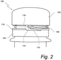
Figure 2 is a diagrammatic lateral view of the embodiment ofFigure 1 where the tethered stopper is unscrewed into a first opening step. -
Figure 3 is a diagrammatic lateral view ofFigure 1 where the tethered stopper is unscrewed into a second opening step. -
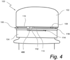
Figure 4 is a diagrammatic lateral view of a tethered stopper in a closed position. - As required, detailed embodiments of the present disclosure are disclosed herein. The disclosed embodiments are merely examples that may be embodied in various and alternative forms, and combinations thereof. As used herein, for example, exemplary, and similar terms, refer expansively to embodiments that serve as an illustration, specimen, model or pattern.
- In some instances, well-known components, systems, materials or methods have not been described in detail in order to avoid obscuring the present disclosure. Therefore, specific structural and functional details disclosed herein are not to be interpreted as limiting, but merely as a basis for the claims and as a representative basis for teaching one skilled in the art to variously employ the present disclosure.
- Phrasing such as 'configured to' perform a function, including in the claims, can include any or all of being sized, shaped, positioned in the arrangement, and comprising material to perform the function.
- Terms indicating quantity, such as 'first' or 'second' are used for exemplary and explanation purposes and are not intended to dictate the specific ordering of a component with respect to other components. Terms indicating position such as 'top' or 'bottom' and 'left' or right' are used for exemplary and explanation purposes with respect to other components.
- Various embodiments of the present disclosure are disclosed herein. The described embodiments are merely exemplary illustrations of implementations set for a clear understanding of the principles of the disclosure. Variations, modifications, and combinations may be made to the described embodiments without departing from the scope of the claims. All such variations, modifications, and combinations are included herein by the scope of this disclosure and the claims.
- This invention is a tethered plastic screw stopper 100 for closing a bottle. The
stopper 100 may be formed by one plastic piece by a molding fabrication step. Other parts or elements of thestopper 100 can be further formed into the plastic piece by cutting or slitting manufacturing step. Thestopper 100 is a screw type and comprises inner fixation features, such as thread(s), designed to cooperate with outer complementary fixation features made on the bottle neck. - The
stopper 100 comprises aclosure shell 102 and atamper band 104 underneath theclosure shell 102. Positioned at the bottom edge thetamper band 104 are the retaining features. The retaining features act to secure thestopper 100 when sealing the bottle. Additionally, the retaining features can be made to form a collar. After the collar is inverted inside thetamper band 104, during the bottle sealing process the collar locks thetamper band 104 and thestopper 100 against a tamper evident ring positioned outwardly around the bottle neck. The retaining features can also be molded directly during the injection process resulting in beads that do not need to be inverted like the collar. -
Tamper band 104 and theclosure shell 102 are separably connected together through aweakness line 106. Theweakness line 106 is positioned between the bottom edge of theclosure shell 102 and the top edge of thetamper band 104. Theweakness line 106 may be formed into the plastic material of thestopper 100 when molding or through a further cutting operation. Theweakness line 106 is formed and comprisesbridges 108. Thesebridges 108 are distributed along theweakness line 106, in regular or irregular spacing. Thebridges 108 link the top edge of thetamper band 104 to the bottom edge of theclosure shell 102. Between thebridges 108, theweakness line 106 comprises spaces or slitting material, with a less thickness, which allow theclosure shell 102 to be removed from thetamper band 104 when opening the bottle by unscrewing thestopper 100. Thus, when unscrewing theclosure shell 102 from thetamper band 104, thebridges 108 are broken. So theclosure shell 102 can be manually removed by the consumer, in order to open the bottle and access the bottle's contents. - The
stopper 100 is tethered and when the bottle is opened, theclosure shell 102 remains attached to thetamper band 104 and is secured on the bottle neck by its retaining features. Thestopper 100 comprises alink 110 formed into aridge 118 on the upper area of thetamper band 104. Typically, theridge 118 has a greater thickness relative to thetamper band 104. Thelink 110 has a small portion of the upper area of thetamper band 104 or of its top edge. - Separation lines 114,115 is formed respectively along the bottom and top of the
link 110 and the top of the remaining material of thetamper band 104. At one end, thelink 110 remains connected to thetamper band 104. One or more of theseparation lines link 110. Theseparation line 114 can be made of a less thick material or of space bridges or of at least one bridge, so when unscrewing theclosure shell 102 theseparation line 114 is torn apart and allows thelink 110 to separate from thetamper band 104. - According to an embodiment, the
link 110 angularly extends around thestopper 100 into thetamper band 104 between 10° to 350°. According to one embodiment thelink 110 angularly extends at 180°. Thebottom separation line 114 of thelink 110 is formed during thestopper 100 manufacturing process or by a cutting or slitting during the manufacturing process. Anopposite end 116 of thelink 110 may also be separated from theridge 118 by a space. In some embodiments as shown inFigures 1 ,2 and3 , theopposite end edge 116 may be inclined or curved. In other embodiments as shown inFigure 4 , theopposite end edge 116 is vertical. - In some embodiments, the
bottom separation line 114 comprises a breakable bridge 400 (Figure 4 ) under theopposite end 116. Thebreakable bridge 400 may be designed to secure theopposite end 116 of thelink 110 when first applying thestopper 100 to the bottle (e.g., during manufacturing). Thebreakable bridge 400 is torn apart and separates when unscrewing the closure shell 102 (e.g., by a user opening the bottle), releasing theopposite end 116 of thelink 110. - At its top end, the
link 110 may be attached to theclosure shell 102 through at least one of thebridges 108 which does not break when unscrewing theclosure shell 102, relative to theother bridges 108 which are torn and broken when unscrewing theclosure shell 102. So when the bottle is opened, the opposite end of thelink 110 remains attached to the closure shell through the at least one remainingbridge 112. The remainingbridge 112 is shown inFigures 2 and3 after opening the bottle. - The remaining
bridge 112 is configured to retain connection between thelink 110 and the bottom edge of theclosure 102. In some embodiments, the reminingbridge 112 be integrally formed (e.g., during molding) as a part of thelink 110. In other embodiments, the remainingbridge 112 is formed independent from thelink 110 and subsequently attached to the link 110 (e.g., during a manufacturing operation). - In another embodiment, multiple remaining
bridges 112 are not broken and are still attached at the link opposite end to theclosure shell 102. The at least two remainingbridges 112, close to each other, stay attached to theclosure shell 102. In some embodiments, the additional remaining bridge is located diametrically opposed to the remaining bridge 112 (i.e., 180 opposite of the remainingbridge 112. In some embodiment, the second remaining bridge is formed at the location of anormal bridge 108. Specifically, the second remaining bridge would replace thenormal bridge 108. - The remaining
bridge 112 has a greater thickness and/or cross-sectional area relative to the otherbreakable bridges 108. For example, the thickness and/or the cross-sectional area of the remainingbridge 112 is at least 30% greater than the respective thickness and cross-sectional area of the normal bridges 108. As another example, the thickness and/or the cross-sectional area of the remainingbridge 112 is 150% or 200% of the section of the normal bridges 108. - In one embodiment, the
bridges 108 and/or the remainingbridge 112 have a square or rectangular shape, so the section of the remainingbridge 112 has a length and/or a width greater than the length and/or width of thebridges 108. In another embodiment, thebridges 108 and/or the remainingbridge 112 have a circular or cylindrical or conical shape, so the section of the remainingbridge 112 has a diameter greater than the diameter of thebridges 108. In some embodiments, the cross-sectional shape of thebridge 108 differs from the cross-sectional shape of the remainingbridge 112. - While various embodiments of the invention have been described, it will be apparent to those of ordinary skill in the art that many more embodiments and implementations are possible that are within the scope of this invention.
Claims (5)
- A tethered plastic screw stopper, comprising:a closure shella tamper band connected to the closure shell by a plurality of bridges that connect a bottom edge of the closure shell to a top edge of the tamper band; anda ridge forming a link that separably connects the closure shell and the tamper band by a weakness line containing a plurality of first bridges and at least one second bridge, wherein the at least one second bridge has a cross-sectional area greater than the cross-sectional area of the first bridges, whereinthe link is formed by a separation line made along the bottom of the link and the top remaining material of the tamper band, the link remaining attached to the tamper band by the at least one second bridge when the plurality of first bridges is broken.
- Tethered plastic screw stopper according to claim 1, wherein there are at least two second bridges diametrically opposed, each configured to remain attached to the closure shell and allow the link to remain attached to the tamper band.
- Tethered plastic screw stopper according to claim 1, wherein the cross-sectional area of the second bridge is 30% greater than the cross-sectional area of the first bridges.
- Tethered plastic screw stopper according to claim 1, wherein the link angularly extends around the stopper into the tamper band between 10° to 350°.
- Tethered plastic screw stopper according to claim 1, wherein the link angularly extends at 180°.
Applications Claiming Priority (3)
| Application Number | Priority Date | Filing Date | Title |
|---|---|---|---|
| US201862755501P | 2018-11-04 | 2018-11-04 | |
| EP19880856.0A EP3877280B1 (en) | 2018-11-04 | 2019-11-04 | Tethered plastic screw stopper |
| PCT/US2019/059712 WO2020093062A2 (en) | 2018-11-04 | 2019-11-04 | Tethered plastic screw stopper |
Related Parent Applications (2)
| Application Number | Title | Priority Date | Filing Date |
|---|---|---|---|
| EP19880856.0A Division EP3877280B1 (en) | 2018-11-04 | 2019-11-04 | Tethered plastic screw stopper |
| EP19880856.0A Division-Into EP3877280B1 (en) | 2018-11-04 | 2019-11-04 | Tethered plastic screw stopper |
Publications (2)
| Publication Number | Publication Date |
|---|---|
| EP4470935A2 true EP4470935A2 (en) | 2024-12-04 |
| EP4470935A3 EP4470935A3 (en) | 2025-03-05 |
Family
ID=70462875
Family Applications (2)
| Application Number | Title | Priority Date | Filing Date |
|---|---|---|---|
| EP19880856.0A Active EP3877280B1 (en) | 2018-11-04 | 2019-11-04 | Tethered plastic screw stopper |
| EP24207256.9A Pending EP4470935A3 (en) | 2018-11-04 | 2019-11-04 | Tethered plastic screw stopper |
Family Applications Before (1)
| Application Number | Title | Priority Date | Filing Date |
|---|---|---|---|
| EP19880856.0A Active EP3877280B1 (en) | 2018-11-04 | 2019-11-04 | Tethered plastic screw stopper |
Country Status (5)
| Country | Link |
|---|---|
| US (2) | US11807436B2 (en) |
| EP (2) | EP3877280B1 (en) |
| CA (1) | CA3111594A1 (en) |
| MX (1) | MX2021003757A (en) |
| WO (1) | WO2020093062A2 (en) |
Families Citing this family (6)
| Publication number | Priority date | Publication date | Assignee | Title |
|---|---|---|---|---|
| US11312544B2 (en) * | 2020-03-30 | 2022-04-26 | ThisCap, Inc. | Cap for container |
| MX2021001474A (en) * | 2018-08-14 | 2021-04-28 | Novembal Usa Inc | Locking bottle transport ring for a stopper. |
| CH718712A1 (en) * | 2021-06-07 | 2022-12-15 | Alpla Werke Alwin Lehner Gmbh & Co Kg | Captive cap. |
| US11975889B2 (en) * | 2021-09-02 | 2024-05-07 | Merrilee Kick | Container apparatus |
| IT202100029978A1 (en) * | 2021-11-26 | 2023-05-26 | Guala Pack Spa | CLOSURE FOR A STRAW OF A THIN-WALLED FLEXIBLE PACKAGING |
| US20260200648A1 (en) * | 2022-10-24 | 2026-07-16 | Dong Jun Lee | Container lid having opening identification function |
Citations (2)
| Publication number | Priority date | Publication date | Assignee | Title |
|---|---|---|---|---|
| US8490805B2 (en) | 2007-11-06 | 2013-07-23 | Tetra Laval Holdings & Finance S.A. | Method and machine for making a stopper for the neck of a container, and stopper as produced by this method |
| US9010555B2 (en) | 2008-10-09 | 2015-04-21 | Tetra Laval Holdings & Finance S.A. | Stopper having a subdivided line of weakness and a method of fabricating such a stopper |
Family Cites Families (14)
| Publication number | Priority date | Publication date | Assignee | Title |
|---|---|---|---|---|
| FR2329536A1 (en) * | 1973-07-02 | 1977-05-27 | Somepla Sa | NEW TIGHT AND TAPPED SCREW CAPSULE |
| FR2499519A1 (en) * | 1981-02-11 | 1982-08-13 | Grussen Jean | SCREW CAPSULE WITH INVIOLABILITY RING |
| EP0107680B1 (en) * | 1982-04-23 | 1986-01-29 | Cebal | Plastic threaded closure cap, with improved tamper-proof strip |
| GB8319444D0 (en) * | 1983-07-19 | 1983-08-17 | Nat Plastics Ltd | Container closure |
| US4805792A (en) * | 1984-04-17 | 1989-02-21 | Continental White Cap, Inc. | Litterless tamper indicating closure |
| US5215204A (en) * | 1992-03-09 | 1993-06-01 | Creative Packaging Corp. | Tamper evident closure with hinged band |
| JP3256344B2 (en) | 1993-07-21 | 2002-02-12 | 日本山村硝子株式会社 | Pill fur proof cap |
| US5725115A (en) * | 1995-02-21 | 1998-03-10 | Crown Cork Ag | Closure cap with tether |
| IT1300020B1 (en) * | 1998-05-08 | 2000-04-04 | Sacmi | SCREW CAP IN PLASTIC MATERIAL WITH GUARANTEE RING. |
| US7789254B2 (en) * | 2004-10-29 | 2010-09-07 | Novelis Inc. | Snap-top closure device |
| RU2478542C2 (en) | 2008-07-08 | 2013-04-10 | Джапан Краун Корк Ко., Лтд. | Container lid made of synthetic resin |
| US8720716B2 (en) * | 2009-06-25 | 2014-05-13 | Phillip John Campbell | Closure with spring loaded tether docking |
| US10836549B2 (en) * | 2015-04-02 | 2020-11-17 | Thiscap Inc. | Cap for container |
| US10654625B2 (en) * | 2018-10-12 | 2020-05-19 | Closure Systems International Inc. | Twist and flip lock closure |
-
2019
- 2019-11-04 CA CA3111594A patent/CA3111594A1/en active Pending
- 2019-11-04 EP EP19880856.0A patent/EP3877280B1/en active Active
- 2019-11-04 MX MX2021003757A patent/MX2021003757A/en unknown
- 2019-11-04 WO PCT/US2019/059712 patent/WO2020093062A2/en not_active Ceased
- 2019-11-04 EP EP24207256.9A patent/EP4470935A3/en active Pending
- 2019-11-04 US US17/290,949 patent/US11807436B2/en active Active
-
2023
- 2023-11-03 US US18/501,325 patent/US20240067423A1/en not_active Abandoned
Patent Citations (2)
| Publication number | Priority date | Publication date | Assignee | Title |
|---|---|---|---|---|
| US8490805B2 (en) | 2007-11-06 | 2013-07-23 | Tetra Laval Holdings & Finance S.A. | Method and machine for making a stopper for the neck of a container, and stopper as produced by this method |
| US9010555B2 (en) | 2008-10-09 | 2015-04-21 | Tetra Laval Holdings & Finance S.A. | Stopper having a subdivided line of weakness and a method of fabricating such a stopper |
Also Published As
| Publication number | Publication date |
|---|---|
| WO2020093062A2 (en) | 2020-05-07 |
| WO2020093062A3 (en) | 2020-07-30 |
| MX2021003757A (en) | 2021-05-27 |
| US20210387778A1 (en) | 2021-12-16 |
| US11807436B2 (en) | 2023-11-07 |
| EP3877280A2 (en) | 2021-09-15 |
| EP4470935A3 (en) | 2025-03-05 |
| EP3877280B1 (en) | 2025-01-01 |
| US20240067423A1 (en) | 2024-02-29 |
| EP3877280A4 (en) | 2022-09-21 |
| CA3111594A1 (en) | 2020-05-07 |
Similar Documents
| Publication | Publication Date | Title |
|---|---|---|
| EP3877279B1 (en) | Tethered plastic screw stopper | |
| EP3877280B1 (en) | Tethered plastic screw stopper | |
| US20220048681A1 (en) | Tethered plastic stopper | |
| US5397009A (en) | Break-away safety cap for containers | |
| US11518591B2 (en) | Strip for securing a stopper to a transport ring of a bottle | |
| US10138035B2 (en) | Tamper evident flip-top closure, method and tool for making the same | |
| RU2701589C2 (en) | Sealing device with unauthorized opening indication | |
| EP3880575B1 (en) | Tethered plastic screw stopper | |
| US20210206537A1 (en) | Tethered plastic stopper | |
| WO2020041640A1 (en) | Tethered stopper and method for making thereof | |
| US20210316908A1 (en) | Tethered plastic stopper | |
| WO2021074726A1 (en) | Tethered plastic screw stopper | |
| WO2021074727A1 (en) | Tethered plastic closure | |
| WO2021074728A1 (en) | Tethered plastic screw stopper | |
| EP3853141B1 (en) | Tethered plastic stopper | |
| US20230056087A1 (en) | Hinged stopper | |
| EP4422984A1 (en) | Plastic tethered stopper for a container | |
| JP6875380B2 (en) | Assembly of containers and reusable tamper-opening explicit closures | |
| US11613412B2 (en) | Tethered plastic stopper | |
| WO2020061582A1 (en) | Tethered plastic stopper |
Legal Events
| Date | Code | Title | Description |
|---|---|---|---|
| PUAI | Public reference made under article 153(3) epc to a published international application that has entered the european phase |
Free format text: ORIGINAL CODE: 0009012 |
|
| STAA | Information on the status of an ep patent application or granted ep patent |
Free format text: STATUS: THE APPLICATION HAS BEEN PUBLISHED |
|
| AC | Divisional application: reference to earlier application |
Ref document number: 3877280 Country of ref document: EP Kind code of ref document: P |
|
| AK | Designated contracting states |
Kind code of ref document: A2 Designated state(s): AL AT BE BG CH CY CZ DE DK EE ES FI FR GB GR HR HU IE IS IT LI LT LU LV MC MK MT NL NO PL PT RO RS SE SI SK SM TR |
|
| PUAL | Search report despatched |
Free format text: ORIGINAL CODE: 0009013 |
|
| AK | Designated contracting states |
Kind code of ref document: A3 Designated state(s): AL AT BE BG CH CY CZ DE DK EE ES FI FR GB GR HR HU IE IS IT LI LT LU LV MC MK MT NL NO PL PT RO RS SE SI SK SM TR |
|
| RIC1 | Information provided on ipc code assigned before grant |
Ipc: B65D 41/34 20060101AFI20250129BHEP |
|
| STAA | Information on the status of an ep patent application or granted ep patent |
Free format text: STATUS: REQUEST FOR EXAMINATION WAS MADE |
|
| 17P | Request for examination filed |
Effective date: 20250903 |