EP4470932A1 - Stackable metal cup - Google Patents
Stackable metal cup Download PDFInfo
- Publication number
- EP4470932A1 EP4470932A1 EP22924073.4A EP22924073A EP4470932A1 EP 4470932 A1 EP4470932 A1 EP 4470932A1 EP 22924073 A EP22924073 A EP 22924073A EP 4470932 A1 EP4470932 A1 EP 4470932A1
- Authority
- EP
- European Patent Office
- Prior art keywords
- inflection point
- inclination angle
- metal cup
- body portion
- region
- Prior art date
- Legal status (The legal status is an assumption and is not a legal conclusion. Google has not performed a legal analysis and makes no representation as to the accuracy of the status listed.)
- Withdrawn
Links
Images
Classifications
-
- B—PERFORMING OPERATIONS; TRANSPORTING
- B65—CONVEYING; PACKING; STORING; HANDLING THIN OR FILAMENTARY MATERIAL
- B65D—CONTAINERS FOR STORAGE OR TRANSPORT OF ARTICLES OR MATERIALS, e.g. BAGS, BARRELS, BOTTLES, BOXES, CANS, CARTONS, CRATES, DRUMS, JARS, TANKS, HOPPERS, FORWARDING CONTAINERS; ACCESSORIES, CLOSURES, OR FITTINGS THEREFOR; PACKAGING ELEMENTS; PACKAGES
- B65D1/00—Rigid or semi-rigid containers having bodies formed in one piece, e.g. by casting metallic material, by moulding plastics, by blowing vitreous material, by throwing ceramic material, by moulding pulped fibrous material or by deep-drawing operations performed on sheet material
- B65D1/22—Boxes or like containers with side walls of substantial depth for enclosing contents
- B65D1/26—Thin-walled containers, e.g. formed by deep-drawing operations
- B65D1/265—Drinking cups
-
- A—HUMAN NECESSITIES
- A47—FURNITURE; DOMESTIC ARTICLES OR APPLIANCES; COFFEE MILLS; SPICE MILLS; SUCTION CLEANERS IN GENERAL
- A47G—HOUSEHOLD OR TABLE EQUIPMENT
- A47G19/00—Table service
- A47G19/22—Drinking vessels or saucers used for table service
- A47G19/23—Drinking vessels or saucers used for table service of stackable type
-
- B—PERFORMING OPERATIONS; TRANSPORTING
- B21—MECHANICAL METAL-WORKING WITHOUT ESSENTIALLY REMOVING MATERIAL; PUNCHING METAL
- B21D—WORKING OR PROCESSING OF SHEET METAL OR METAL TUBES, RODS OR PROFILES WITHOUT ESSENTIALLY REMOVING MATERIAL; PUNCHING METAL
- B21D51/00—Making hollow objects
- B21D51/16—Making hollow objects characterised by the use of the objects
- B21D51/18—Making hollow objects characterised by the use of the objects vessels, e.g. tubs, vats, tanks, sinks, or the like
-
- B—PERFORMING OPERATIONS; TRANSPORTING
- B65—CONVEYING; PACKING; STORING; HANDLING THIN OR FILAMENTARY MATERIAL
- B65D—CONTAINERS FOR STORAGE OR TRANSPORT OF ARTICLES OR MATERIALS, e.g. BAGS, BARRELS, BOTTLES, BOXES, CANS, CARTONS, CRATES, DRUMS, JARS, TANKS, HOPPERS, FORWARDING CONTAINERS; ACCESSORIES, CLOSURES, OR FITTINGS THEREFOR; PACKAGING ELEMENTS; PACKAGES
- B65D1/00—Rigid or semi-rigid containers having bodies formed in one piece, e.g. by casting metallic material, by moulding plastics, by blowing vitreous material, by throwing ceramic material, by moulding pulped fibrous material or by deep-drawing operations performed on sheet material
- B65D1/40—Details of walls
-
- B—PERFORMING OPERATIONS; TRANSPORTING
- B65—CONVEYING; PACKING; STORING; HANDLING THIN OR FILAMENTARY MATERIAL
- B65D—CONTAINERS FOR STORAGE OR TRANSPORT OF ARTICLES OR MATERIALS, e.g. BAGS, BARRELS, BOTTLES, BOXES, CANS, CARTONS, CRATES, DRUMS, JARS, TANKS, HOPPERS, FORWARDING CONTAINERS; ACCESSORIES, CLOSURES, OR FITTINGS THEREFOR; PACKAGING ELEMENTS; PACKAGES
- B65D21/00—Nestable, stackable or joinable containers; Containers of variable capacity
- B65D21/02—Containers specially shaped, or provided with fittings or attachments, to facilitate nesting, stacking, or joining together
- B65D21/0233—Nestable containers
-
- B—PERFORMING OPERATIONS; TRANSPORTING
- B65—CONVEYING; PACKING; STORING; HANDLING THIN OR FILAMENTARY MATERIAL
- B65D—CONTAINERS FOR STORAGE OR TRANSPORT OF ARTICLES OR MATERIALS, e.g. BAGS, BARRELS, BOTTLES, BOXES, CANS, CARTONS, CRATES, DRUMS, JARS, TANKS, HOPPERS, FORWARDING CONTAINERS; ACCESSORIES, CLOSURES, OR FITTINGS THEREFOR; PACKAGING ELEMENTS; PACKAGES
- B65D25/00—Details of other kinds or types of rigid or semi-rigid containers
- B65D25/14—Linings or internal coatings
-
- B—PERFORMING OPERATIONS; TRANSPORTING
- B65—CONVEYING; PACKING; STORING; HANDLING THIN OR FILAMENTARY MATERIAL
- B65D—CONTAINERS FOR STORAGE OR TRANSPORT OF ARTICLES OR MATERIALS, e.g. BAGS, BARRELS, BOTTLES, BOXES, CANS, CARTONS, CRATES, DRUMS, JARS, TANKS, HOPPERS, FORWARDING CONTAINERS; ACCESSORIES, CLOSURES, OR FITTINGS THEREFOR; PACKAGING ELEMENTS; PACKAGES
- B65D25/00—Details of other kinds or types of rigid or semi-rigid containers
- B65D25/34—Coverings or external coatings
Definitions
- the present invention relates to a stackable metal cup that can be stacked to be stored.
- cup-shaped vessels made of paper or plastic have been widely used for drinking or the like. This is because vessels formed of such materials are lightweight, easy to form, inexpensive, and suitable for disposable use.
- metal cups are stronger and more durable than cups made of paper or plastic and are suitable for repeated use, and thus can significantly contribute to reducing depletion of resources and generation of waste.
- Metal cups are often used for drinking alcoholic beverages such as beer, and come in a range of sizes such as a small mug to a large mug.
- Metal cups also have a shape in which an inner diameter of an opening at an upper end is set to be larger than an outer diameter of a bottom portion to enable the cups to be stacked.
- a metal cup having such a form as disclosed in Patent Document 1, for example, two to three steps are formed in the middle of the body portion.
- the body portion can be formed as a tapered inclined wall. However, even in this case, for example, about two steps are formed in the body portion wall (inclined wall). For all types of metal cups, close contact between the body portion walls is suppressed when a plurality of the cups are stacked such that the stacked metal cups can be smoothly inserted and removed.
- a metal can typically an aluminum can
- the thickness of a metal cup has been reduced to an extremely thin thickness by drawing and ironing, and the thickness of a metal cup has also been reduced, whereby weight reduction and resource saving have been achieved.
- thinning of the body portion wall brings about the above-mentioned advantages, it also brings about problems that strength is lowered, the metal cup is easily deformed, and a stacking property is impaired.
- an object of the present invention is to provide a stackable metal cup in which deterioration of the stacking property due to deformation of the metal cup is effectively prevented.
- a stackable metal cup including: a body portion having a hollow shape with an open upper portion and having a shape inclined from the upper portion toward a lower portion such that an upper end inner diameter is larger than a lower end outer diameter; and a bottom portion including a grounding portion, the grounding portion being continuous with a lower end of the body portion via a curvature portion, in which when a height H from the grounding portion to the upper end is 100%, an upper region A1 having a height of 70% to 100% includes at least one inflection point portion ⁇ at which an inclination angle of the body portion with respect to a vertical plane changes.
- the upper end inner diameter of the body portion is set to be larger than the outer diameter of the lower end, thereby ensuring the stacking property.
- a particularly important feature is that the resistance of the body portion wall against the pressure from the circumferential direction is enhanced by the inflection point portion ⁇ generated by the change in the inclination angle of the body portion wall (i.e., inclination angle difference) to suppress the shape change. That is, in the present invention, one or more inflection point portions ⁇ are formed in the upper region A1 (a region having a height of 70% to 100%). Therefore, the upper end of the metal cup is less likely to be deformed. For example, even when the lower portion is deformed, the shape of the upper end of the opening is not deformed, so that the stacking property is not impaired. This is the greatest advantage of the present invention.
- one or more inflection point portions ⁇ as described above are also formed in the lower region A2 (the region having a height of 40% or less). That is, the lower region A2 is also less likely to be deformed, and not only the upper end portion but also the lower end portion of the opening is less likely to be deformed. In short, the shape of the upper portion and the shape of the lower portion, which are most important for ensuring the stacking property, are less likely to be deformed, and hence the stacking property is more stably ensured.
- inflection point portions ⁇ as described above are also formed in the intermediate region A3 between the upper region A1 and the lower region A2, and further, the angle difference ⁇ defining such inflection point portions ⁇ is smaller than the angle difference ⁇ in the upper region A1 and the lower region A2, and is, for example, a level difference which is slightly felt by touch. That is, the intermediate region A3 is a portion where the metal cup is frequently gripped by a hand. Since this region is a portion where deformation occurs most frequently, it is better to provide many inflection point portions ⁇ .
- the inflection point portion formed by the angle difference ⁇ of the same degree as the upper region A1 and the lower region A2 is large enough to be clearly recognized as a step, and when the inflection point portion recognized as such a step increases, the smoothness of the body portion wall is impaired, and for example, printability, labelability, and the like are impaired. Further, when the cups are stacked, the stacked cups may rattle, and the stability of the stacked cups may be impaired. Therefore, in the intermediate region A3, the inflection point portion ⁇ is formed by a slight angle difference which is not easily recognized as a step, and the strength is improved while preventing the above-described disadvantage.
- a metal cup according to the present invention which is overall denoted by 1, includes a body portion 3 and a bottom portion 7 provided with a grounding portion 5.
- a curled portion 9 is formed at an upper end of the body portion 3 so as not to expose a sharp edge portion to the outside.
- a lower end of the body portion 3 is continuous with the grounding portion 5 via a curvature portion R.
- the bottom portion 7 may be flat, but normally has a shape in which a central portion is recessed in a dome shape, and a peripheral edge of the dome-shaped recessed portion serves as the grounding portion 5. With such a configuration, the metal cup 1 has high buckling resistance.
- the body portion 3 forms a hollow portion 10 that has an open upper end and is closed by the bottom portion 7 so as to accommodate a liquid such as a beverage depending on the intended usage.
- the opening diameter D at the upper end of the hollow portion 10 (i.e., the inner diameter at the upper end of the body portion 3) is larger than the outer diameter d at the lower end, and the hollow portion 10 is inclined downward.
- the metal serving as a constituent material of the metal cup 1 may be any metal or alloy material, and may be, for example, aluminum, copper, iron, an alloy containing these metals, a tin-plated steel plate such as a tin plate, or a surface-treated steel plate such as an aluminum plate subjected to chemical conversion treatment.
- steel, stainless steel, aluminum, or an aluminum alloy is preferable, and aluminum or an aluminum alloy is particularly preferable from the viewpoint of lightness and workability.
- an organic resin coating may be laminated on the inner surface of the metal cup 1.
- the organic resin coating is a coating derived from a coating material such as an acrylic coating material, a urethane coating material, a silicon coating material, or a fluorine-based coating material, or a thermoplastic resin such as polyethylene terephthalate (PET), and is provided to give corrosion resistance and suppress surface roughness during harsh formation processes.
- a coating material such as an acrylic coating material, a urethane coating material, a silicon coating material, or a fluorine-based coating material, or a thermoplastic resin such as polyethylene terephthalate (PET)
- PET polyethylene terephthalate
- an organic resin coating may also be formed on the outer surface.
- Such a metal cup 1 can be formed using, for example, a thin raw plate made of metal (the above-described organic resin coating may be formed on the inner surface and also on the surface on the side to be the outer surface).
- the thickness of a central portion of the bottom portion 7 corresponds to the thickness of the blank sheet used in forming the cup 1 and is typically from 0.10 to 0.50 mm, though the thickness varies depending on the intended usage of the cup 1.
- the thickness of the body portion 3 and a height H of the cup vary depending on the degree of ironing.
- the body portion 3 is made progressively thinner and the height H is progressively increased as ironing is performed in multiple stages by gradually increasing the ironing ratio.
- metal cups have become remarkably thin. To cope with such thinning, the metal cup 1 of the present invention has the following form.
- the body portion 3 has a large number of portions where the inclination angle (angle with respect to a vertical plane) changes, and an inflection point portion ⁇ is generated due to the angle difference ⁇ of the inclination angle.
- the inflection point portion ⁇ is clearly visually recognized as a step.
- Such an inflection point portion ⁇ exhibits resistance to stress from the outer surface in the circumferential direction of the body portion 3 of the metal cup 1, and effectively suppresses deformation of the body portion 3.
- an inclination angle means an angle with respect to a vertical plane unless otherwise specified.
- a reference vertical wall 3a having an inclination angle of 2 degrees or less, particularly 1 degree or less, and preferably 0.5 degrees or less (that is, the inclination angle is substantially zero) with respect to a vertical plane and the inclined wall 3b having an angle difference ⁇ with respect to the reference vertical wall 3a are alternately continued, and a plurality of inflection point portions ⁇ are formed.
- the inclination angle of the reference vertical wall 3a is smaller than the angle difference ⁇ .
- the angle difference ⁇ (that is, the angle difference from the reference vertical wall 3a) is in a range of 25 degrees or less, and the angle differences ⁇ forming the plurality of inflection point portions ⁇ may be uniformly the same or may be different values on the condition that the inclination angle is 25 degrees or less.
- the inclination angle of the body portion 3 with respect to a vertical plane and the angle difference ⁇ from the vertical wall 3a are naturally set to satisfy the condition that the opening diameter D of the upper end of the hollow portion 10 is larger than the outer diameter d of the lower end.
- ⁇ is set to be larger than necessary, the outer diameter d of the lower end becomes smaller than necessary, or the number of inflection point portions ⁇ (steps) is limited, and further, the flatness of the outer surface of the body portion 3 is impaired, and the printability and the label-sticking property are impaired.
- the inclination angle (angle with respect to a vertical plane) of the body portion 3 is set to 7 degrees or less, and the angle difference ⁇ is set to 5 degrees or less, particularly 1 degree or less, and most preferably 0.5 degrees or less.
- the number of inflection point portions ⁇ can be appropriately increased. For example, it is not desirable to form the inflection point portion by a recessed portion that is recessed in the horizontal direction.
- the metal cup 1 including the body portion 3 having the inflection point portion ⁇ as described above can be divided into three regions of an upper region A1 having a height of 70% to 100%, a lower region A2 having a height of 40% or less of H, and an intermediate region A3 between the regions A1 and A2.
- the inflection point portion ⁇ due to the angle difference ⁇ as described above is distributed in each of these regions.
- the upper region A1 at least one, preferably two to four inflection point portions ⁇ generated by the angle difference ⁇ of the inclination angle of the body portion 3 are formed. Accordingly, it is possible to increase the strength of the upper region A1, it is possible to effectively suppress the deformation of the upper end portion of the hollow opening 10, and it is possible to secure the stacking property.
- the lower region A2 at least one, preferably three to five inflection point portions ⁇ generated by the angle difference ⁇ of the inclination angle of the body portion 3 are formed.
- the angle difference ⁇ between the inclination angles in the upper region A1 and the lower region A2 is set to 25 degrees or less.
- the reference vertical wall 3a having a very small inclination angle (or zero inclination angle) with respect to a vertical plane and the inclined wall 3b having an angle difference ⁇ with respect to the reference vertical wall 3a are alternately connected, but a wall having a different inclination angle (for example, a tapered wall having an inclination angle larger than that of the inclined wall 3b) may be further formed between the reference vertical wall 3a and the inclined wall 3b as long as the angle difference ⁇ is 25 degrees or less.
- the inflection point portion ⁇ is also formed between the tapered wall and the inclined wall 3b and between the tapered wall and the reference vertical wall 3a.
- the present invention it is optimal to form at least four, preferably 6 to 10 inflection point portions ⁇ generated by the angle difference ⁇ of the inclination angle also in the intermediate region A3. That is, the metal cup 1 is most often used for drinking alcoholic beverages such as beer. Therefore, the portion of the intermediate region A3 is a portion which is most strongly gripped and is easily deformed. Therefore, to increase the strength of this portion, it is preferable to form the number of inflection point portions ⁇ as described above.
- the intermediate region A3 is large, if the intermediate region A3 is flat, when the metal cups 1 are stacked, a region in which the upper and lower cups 1 stacked on each other are in close contact with each other is increased, and thus there is a concern that stacking property may be deteriorated. It is preferable to form a large number of inflection point portions ⁇ to avoid such a decrease in stacking performance.
- the intermediate region A3 is large and located in the central portion of the metal cup 1. For this reason, it is very frequent that printing is performed or a label or the like is attached to this portion. Therefore, high smoothness is required in this region.
- the angle difference ⁇ of the inclination angle in the intermediate region A3 is preferably formed to be smaller than those in the upper region A1 and the lower region A2, and all of the plurality of angle differences ⁇ are preferably 5 degrees or less, particularly preferably 1 degree or less, and most preferably 0.5 degrees or less.
- the inflection point portion ⁇ due to such a small angle difference indicates a slight step that can be recognized by the sense of touch, and is inferior to the inflection point portion ⁇ in the upper region A1 or the lower region A2 in terms of high strength.
- the inflection point portion ⁇ having such a small angle difference is sufficient in terms of ensuring the stacking property, and further, by setting the number of inflection point portions ⁇ to be large (by reducing the interval between the adjacent inflection point portions ⁇ ), the strength can be increased to some extent, which is the most preferable aspect.
- the height H is in a range of 90 to 150 mm and the upper end inner diameter of the opening is in a range of 65 to 95 mm, particularly 70 to 90 mm.
- curled portion 9 is formed at the upper end in the above-described example, a horizontal flange or the like may be formed instead of the curled portion 9 and a lid member may be provided by heat sealing or the like after a food product or the like is accommodated. This is advantageous in storing the cup when the cup is repeatedly used.
- the metal cup 1 may be used as a can to which a lid member is attached after the metal cup 1 is filled with a beverage or the like.
- the lid member may be any stay-on-tab lid made of metal, a sheet made of a layered body, a screw lid, or the like.
- the lid member In a case in which the lid member is wound and tightened on the upper end of the body portion as a stay-on-tab lid, the upper end of the body portion of the container need only be subjected to trimming for the winding and tightening and subsequently subjected to flanging that forms a face portion.
- the lid member is bonded by heat or other means to the upper end of the body portion as a sheet composed of a layered body
- the upper end of the body portion of the container may be imparted with a shape that includes a face portion to ensure the bonding area.
- a laminate having a layer made of an adhesive such as a known sealant film, a lacquer-type adhesive, an easy-peel adhesive, or a hot-melt adhesive can be adopted as the thermal adhesive layer.
- the lid member When the lid member is screw-fixed to the upper end of the body portion as a screw lid, the upper end of the body portion of the container may have a screw thread, or a lid member with a spout having a separate screw thread for screw-fixing the screw lid may be wound and fastened to the upper end of the body portion of the container.
Landscapes
- Engineering & Computer Science (AREA)
- Mechanical Engineering (AREA)
- Ceramic Engineering (AREA)
- Stackable Containers (AREA)
- Containers Having Bodies Formed In One Piece (AREA)
- Rigid Containers With Two Or More Constituent Elements (AREA)
- Table Devices Or Equipment (AREA)
Abstract
Description
- The present invention relates to a stackable metal cup that can be stacked to be stored.
- Conventionally, cup-shaped vessels made of paper or plastic have been widely used for drinking or the like. This is because vessels formed of such materials are lightweight, easy to form, inexpensive, and suitable for disposable use. However, in recent years, the focus has shifted to metal cups to address environmental issues such as resource depletion and problems causes by waste. Metal cups are stronger and more durable than cups made of paper or plastic and are suitable for repeated use, and thus can significantly contribute to reducing depletion of resources and generation of waste.
- Metal cups are often used for drinking alcoholic beverages such as beer, and come in a range of sizes such as a small mug to a large mug. Metal cups also have a shape in which an inner diameter of an opening at an upper end is set to be larger than an outer diameter of a bottom portion to enable the cups to be stacked. In a metal cup having such a form, as disclosed in
Patent Document 1, for example, two to three steps are formed in the middle of the body portion. In addition, as described in Patent Document 2, to make the inner diameter of the opening at the upper end larger than the outer diameter of the bottom portion, the body portion can be formed as a tapered inclined wall. However, even in this case, for example, about two steps are formed in the body portion wall (inclined wall). For all types of metal cups, close contact between the body portion walls is suppressed when a plurality of the cups are stacked such that the stacked metal cups can be smoothly inserted and removed. - That is, in the metal cups of
Patent Documents 1 and 2, since steps are formed in the body portion wall, a gap is formed between the outer surface of the body portion wall of the stacked upper cup and the inner surface of the body portion wall of the lower cup holding the upper cup, and a portion where the cups are in close contact with each other is significantly reduced. Thus, not only can the cups be easily stacked but also the stacked cups can be easily pulled out. -
- Patent Document 1:
JP 2015-506842 A - Patent Document 2:
JP 2021-155121 A - With the development of metal processing techniques in recent years, the thickness of a metal can, typically an aluminum can, has been reduced to an extremely thin thickness by drawing and ironing, and the thickness of a metal cup has also been reduced, whereby weight reduction and resource saving have been achieved. However, although such thinning of the body portion wall brings about the above-mentioned advantages, it also brings about problems that strength is lowered, the metal cup is easily deformed, and a stacking property is impaired.
- Accordingly, an object of the present invention is to provide a stackable metal cup in which deterioration of the stacking property due to deformation of the metal cup is effectively prevented.
- According to the present invention, there is provided a stackable metal cup including: a body portion having a hollow shape with an open upper portion and having a shape inclined from the upper portion toward a lower portion such that an upper end inner diameter is larger than a lower end outer diameter; and a bottom portion including a grounding portion, the grounding portion being continuous with a lower end of the body portion via a curvature portion, in which
when a height H from the grounding portion to the upper end is 100%, an upper region A1 having a height of 70% to 100% includes at least one inflection point portion α at which an inclination angle of the body portion with respect to a vertical plane changes. - In the stackable metal cup of the present invention, the following aspects are suitably adopted.
- (1) The at least one inflection point portion α at which the inclination angle of the body portion changes is formed in a lower region A2 having a height of 40% or less.
- (2) An inclination angle difference ΔΘ defining the inflection point portion α is 25 degrees or less.
- (3) At least four of the inflection point portions α at which the inclination angle of the body portion changes are formed in an intermediate region A1 between the upper region A2 and the lower region A3.
- (4) The inflection point portion α is an intersection between a reference vertical wall having an inclination angle of 2 degrees or less with respect to a vertical plane and an inclined wall having an inclination angle difference ΔΘ with respect to the reference vertical wall.
- (5) Inclination angle differences ΔΘ defining the inflection point portions α formed in the intermediate region A3 are all smaller than inclination angle differences Δθ defining the inflection point portions α existing in the upper region A1 and the lower region A2.
- (6) Each of the inclination angle differences ΔΘ defining the inflection point portions α formed in the intermediate region A3 is 10 degrees or less.
- (7) The height H from the grounding portion to the upper end is in a range of 90 to 150 mm, and the upper end inner diameter of the opening is in a range of 65 to 95 mm.
- In the metal cup of the present invention, as a whole, the upper end inner diameter of the body portion is set to be larger than the outer diameter of the lower end, thereby ensuring the stacking property. A particularly important feature is that the resistance of the body portion wall against the pressure from the circumferential direction is enhanced by the inflection point portion α generated by the change in the inclination angle of the body portion wall (i.e., inclination angle difference) to suppress the shape change. That is, in the present invention, one or more inflection point portions α are formed in the upper region A1 (a region having a height of 70% to 100%). Therefore, the upper end of the metal cup is less likely to be deformed. For example, even when the lower portion is deformed, the shape of the upper end of the opening is not deformed, so that the stacking property is not impaired. This is the greatest advantage of the present invention.
- In the metal cup preferred in the present invention, one or more inflection point portions α as described above are also formed in the lower region A2 (the region having a height of 40% or less). That is, the lower region A2 is also less likely to be deformed, and not only the upper end portion but also the lower end portion of the opening is less likely to be deformed. In short, the shape of the upper portion and the shape of the lower portion, which are most important for ensuring the stacking property, are less likely to be deformed, and hence the stacking property is more stably ensured.
- Further, in the most preferred embodiment of the present invention, four or more inflection point portions α as described above are also formed in the intermediate region A3 between the upper region A1 and the lower region A2, and further, the angle difference Δθ defining such inflection point portions α is smaller than the angle difference ΔΘ in the upper region A1 and the lower region A2, and is, for example, a level difference which is slightly felt by touch. That is, the intermediate region A3 is a portion where the metal cup is frequently gripped by a hand. Since this region is a portion where deformation occurs most frequently, it is better to provide many inflection point portions α. However, the inflection point portion formed by the angle difference ΔΘ of the same degree as the upper region A1 and the lower region A2 is large enough to be clearly recognized as a step, and when the inflection point portion recognized as such a step increases, the smoothness of the body portion wall is impaired, and for example, printability, labelability, and the like are impaired. Further, when the cups are stacked, the stacked cups may rattle, and the stability of the stacked cups may be impaired. Therefore, in the intermediate region A3, the inflection point portion α is formed by a slight angle difference which is not easily recognized as a step, and the strength is improved while preventing the above-described disadvantage.
-
-
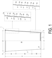
FIG. 1 is a schematic side cross-sectional view illustrating an example of a metal cup of the present invention and a partially enlarged cross-sectional view of a body portion. -
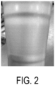
FIG. 2 is a partially enlarged photograph of an intermediate region A3 illustrating an example of the metal cup of the present invention. - In
FIG. 1 , a metal cup according to the present invention, which is overall denoted by 1, includes a body portion 3 and abottom portion 7 provided with agrounding portion 5. Typically, acurled portion 9 is formed at an upper end of the body portion 3 so as not to expose a sharp edge portion to the outside. A lower end of the body portion 3 is continuous with the groundingportion 5 via a curvature portion R. - The
bottom portion 7 may be flat, but normally has a shape in which a central portion is recessed in a dome shape, and a peripheral edge of the dome-shaped recessed portion serves as thegrounding portion 5. With such a configuration, themetal cup 1 has high buckling resistance. - The body portion 3 forms a
hollow portion 10 that has an open upper end and is closed by thebottom portion 7 so as to accommodate a liquid such as a beverage depending on the intended usage. - In the
metal cup 1 described above, to ensure stacking property, the opening diameter D at the upper end of the hollow portion 10 (i.e., the inner diameter at the upper end of the body portion 3) is larger than the outer diameter d at the lower end, and thehollow portion 10 is inclined downward. - Note that the metal serving as a constituent material of the
metal cup 1 may be any metal or alloy material, and may be, for example, aluminum, copper, iron, an alloy containing these metals, a tin-plated steel plate such as a tin plate, or a surface-treated steel plate such as an aluminum plate subjected to chemical conversion treatment. In general, steel, stainless steel, aluminum, or an aluminum alloy is preferable, and aluminum or an aluminum alloy is particularly preferable from the viewpoint of lightness and workability. - Further, an organic resin coating may be laminated on the inner surface of the
metal cup 1. The organic resin coating is a coating derived from a coating material such as an acrylic coating material, a urethane coating material, a silicon coating material, or a fluorine-based coating material, or a thermoplastic resin such as polyethylene terephthalate (PET), and is provided to give corrosion resistance and suppress surface roughness during harsh formation processes. Of course, an organic resin coating may also be formed on the outer surface. - Such a
metal cup 1 can be formed using, for example, a thin raw plate made of metal (the above-described organic resin coating may be formed on the inner surface and also on the surface on the side to be the outer surface). - For example, in a case where an organic resin film is formed, punching, drawing, redrawing-ironing, and substantially simultaneously doming of the bottom portion are performed, followed by heat treatment of the trimming portion (to prevent peeling of the film), trimming, curling, redrawing to provide a slope on the side wall, heat treatment (removal of resin strain and wax), outer surface printing, heat treatment, and the like.
- In a case where the organic coating resin is not formed, punching, drawing, redrawing-ironing, and doming of the bottom portion are performed substantially at the same time, and then trimming, washing and drying, a curling step, a redrawing step of providing an inclination to the side wall, outer surface printing, heat treatment, and the like are performed.
- In the
metal cup 1 described above, the thickness of a central portion of thebottom portion 7 corresponds to the thickness of the blank sheet used in forming thecup 1 and is typically from 0.10 to 0.50 mm, though the thickness varies depending on the intended usage of thecup 1. The thickness of the body portion 3 and a height H of the cup (height from the groundingportion 5 to the upper end of the body portion 3) vary depending on the degree of ironing. The body portion 3 is made progressively thinner and the height H is progressively increased as ironing is performed in multiple stages by gradually increasing the ironing ratio. In recent years in particular, metal cups have become remarkably thin. To cope with such thinning, themetal cup 1 of the present invention has the following form. - As illustrated in
FIG. 1 , the body portion 3 has a large number of portions where the inclination angle (angle with respect to a vertical plane) changes, and an inflection point portion α is generated due to the angle difference ΔΘ of the inclination angle. When the angle difference ΔΘ is large, the inflection point portion α is clearly visually recognized as a step. Such an inflection point portion α exhibits resistance to stress from the outer surface in the circumferential direction of the body portion 3 of themetal cup 1, and effectively suppresses deformation of the body portion 3. - In the following description, an inclination angle means an angle with respect to a vertical plane unless otherwise specified.
- For example, in the example illustrated in
FIG. 1 , a referencevertical wall 3a having an inclination angle of 2 degrees or less, particularly 1 degree or less, and preferably 0.5 degrees or less (that is, the inclination angle is substantially zero) with respect to a vertical plane and theinclined wall 3b having an angle difference ΔΘ with respect to the referencevertical wall 3a are alternately continued, and a plurality of inflection point portions α are formed. In this case, the inclination angle of the referencevertical wall 3a is smaller than the angle difference ΔΘ. The angle difference ΔΘ (that is, the angle difference from the referencevertical wall 3a) is in a range of 25 degrees or less, and the angle differences ΔΘ forming the plurality of inflection point portions α may be uniformly the same or may be different values on the condition that the inclination angle is 25 degrees or less. - In the present invention, the inclination angle of the body portion 3 with respect to a vertical plane and the angle difference ΔΘ from the
vertical wall 3a are naturally set to satisfy the condition that the opening diameter D of the upper end of thehollow portion 10 is larger than the outer diameter d of the lower end. However, when ΔΘ is set to be larger than necessary, the outer diameter d of the lower end becomes smaller than necessary, or the number of inflection point portions α (steps) is limited, and further, the flatness of the outer surface of the body portion 3 is impaired, and the printability and the label-sticking property are impaired. From such a viewpoint, it is preferable that the inclination angle (angle with respect to a vertical plane) of the body portion 3 is set to 7 degrees or less, and the angle difference ΔΘ is set to 5 degrees or less, particularly 1 degree or less, and most preferably 0.5 degrees or less. Thus, the number of inflection point portions α can be appropriately increased. For example, it is not desirable to form the inflection point portion by a recessed portion that is recessed in the horizontal direction. - When the height H of the body portion 3 is 100%, the
metal cup 1 including the body portion 3 having the inflection point portion α as described above can be divided into three regions of an upper region A1 having a height of 70% to 100%, a lower region A2 having a height of 40% or less of H, and an intermediate region A3 between the regions A1 and A2. In the present invention, the inflection point portion α due to the angle difference ΔΘ as described above is distributed in each of these regions. - First, in the upper region A1, at least one, preferably two to four inflection point portions α generated by the angle difference ΔΘ of the inclination angle of the body portion 3 are formed. Accordingly, it is possible to increase the strength of the upper region A1, it is possible to effectively suppress the deformation of the upper end portion of the
hollow opening 10, and it is possible to secure the stacking property. - Further, in the lower region A2, at least one, preferably three to five inflection point portions α generated by the angle difference ΔΘ of the inclination angle of the body portion 3 are formed. As a result, it is possible to increase the strength of the lower region A2 together with the upper region A1, it is possible to effectively suppress the deformation of the upper end portion and the lower end portion of the
hollow opening 10, and it is possible to more reliably secure the stacking property. That is, at the time of stacking, not only the reception of themetal cup 1 but also the insertion of themetal cup 1 can be smoothly performed. - As described above, the angle difference ΔΘ between the inclination angles in the upper region A1 and the lower region A2 is set to 25 degrees or less.
- Further, in
FIG. 1 , the referencevertical wall 3a having a very small inclination angle (or zero inclination angle) with respect to a vertical plane and theinclined wall 3b having an angle difference ΔΘ with respect to the referencevertical wall 3a are alternately connected, but a wall having a different inclination angle (for example, a tapered wall having an inclination angle larger than that of theinclined wall 3b) may be further formed between the referencevertical wall 3a and theinclined wall 3b as long as the angle difference ΔΘ is 25 degrees or less. In this case, the inflection point portion α is also formed between the tapered wall and theinclined wall 3b and between the tapered wall and the referencevertical wall 3a. - Further, in the present invention, it is optimal to form at least four, preferably 6 to 10 inflection point portions α generated by the angle difference ΔΘ of the inclination angle also in the intermediate region A3. That is, the
metal cup 1 is most often used for drinking alcoholic beverages such as beer. Therefore, the portion of the intermediate region A3 is a portion which is most strongly gripped and is easily deformed. Therefore, to increase the strength of this portion, it is preferable to form the number of inflection point portions α as described above. In addition, since the intermediate region A3 is large, if the intermediate region A3 is flat, when themetal cups 1 are stacked, a region in which the upper andlower cups 1 stacked on each other are in close contact with each other is increased, and thus there is a concern that stacking property may be deteriorated. It is preferable to form a large number of inflection point portions α to avoid such a decrease in stacking performance. - Referring also to
FIG. 2 illustrating the intermediate region A3, the intermediate region A3 is large and located in the central portion of themetal cup 1. For this reason, it is very frequent that printing is performed or a label or the like is attached to this portion. Therefore, high smoothness is required in this region. From such a viewpoint, the angle difference ΔΘ of the inclination angle in the intermediate region A3 is preferably formed to be smaller than those in the upper region A1 and the lower region A2, and all of the plurality of angle differences Δθ are preferably 5 degrees or less, particularly preferably 1 degree or less, and most preferably 0.5 degrees or less. As can be understood fromFIG. 2 , the inflection point portion α due to such a small angle difference indicates a slight step that can be recognized by the sense of touch, and is inferior to the inflection point portion α in the upper region A1 or the lower region A2 in terms of high strength. However, even the inflection point portion α having such a small angle difference is sufficient in terms of ensuring the stacking property, and further, by setting the number of inflection point portions α to be large (by reducing the interval between the adjacent inflection point portions α), the strength can be increased to some extent, which is the most preferable aspect. - As described above, since the
metal cup 1 of the present invention described above is frequently used instead of a mug when drinking beer, it is most preferable that the height H is in a range of 90 to 150 mm and the upper end inner diameter of the opening is in a range of 65 to 95 mm, particularly 70 to 90 mm. - Although the curled
portion 9 is formed at the upper end in the above-described example, a horizontal flange or the like may be formed instead of the curledportion 9 and a lid member may be provided by heat sealing or the like after a food product or the like is accommodated. This is advantageous in storing the cup when the cup is repeatedly used. - Further, the
metal cup 1 may be used as a can to which a lid member is attached after themetal cup 1 is filled with a beverage or the like. The lid member may be any stay-on-tab lid made of metal, a sheet made of a layered body, a screw lid, or the like. - In a case in which the lid member is wound and tightened on the upper end of the body portion as a stay-on-tab lid, the upper end of the body portion of the container need only be subjected to trimming for the winding and tightening and subsequently subjected to flanging that forms a face portion.
- In a case in which the lid member is bonded by heat or other means to the upper end of the body portion as a sheet composed of a layered body, the upper end of the body portion of the container may be imparted with a shape that includes a face portion to ensure the bonding area. As the sheet made of a laminate, a laminate having a layer made of an adhesive such as a known sealant film, a lacquer-type adhesive, an easy-peel adhesive, or a hot-melt adhesive can be adopted as the thermal adhesive layer.
- When the lid member is screw-fixed to the upper end of the body portion as a screw lid, the upper end of the body portion of the container may have a screw thread, or a lid member with a spout having a separate screw thread for screw-fixing the screw lid may be wound and fastened to the upper end of the body portion of the container. By adapting to the attachment form of the lid member, the efficiency in storing and transporting the container portion can be improved regardless of the lid member.
-
- 1: Metal cup
- 3: Body portion
- R: Curvature portion
- 5: Grounding portion
- 7: Bottom portion
- 9: Curled portion
- 10: Hollow space
- α: Inflection point portion
Claims (8)
- A stackable metal cup comprising:a body portion having a hollow shape with an open upper portion and having a shape inclined from the upper portion toward a lower portion such that an upper end inner diameter is larger than a lower end outer diameter; anda bottom portion including a grounding portion, the grounding portion being continuous with a lower end of the body portion via a curvature portion, whereinwhen a height H from the grounding portion to the upper end is 100%, an upper region A1 having a height of 70% to 100% includes at least one inflection point portion α at which an inclination angle of the body portion with respect to a vertical plane changes.
- The stackable metal cup according to claim 1, wherein
the at least one inflection point portion α at which the inclination angle of the body portion changes is formed in a lower region A2 having a height of 40% or less. - The stackable metal cup according to claim 1, wherein
an inclination angle difference ΔΘ defining the inflection point portion α is 25 degrees or less. - The stackable metal cup according to claim 1, wherein
at least four of the inflection point portions α at which the inclination angle of the body portion changes are formed in an intermediate region A3 between the upper region A1 and the lower region A2. - The stackable metal cup according to claim 1, wherein
the inflection point portion α is an intersection between a reference vertical wall having an inclination angle of 2 degrees or less with respect to a vertical plane and an inclined wall having an inclination angle difference Δθ with respect to the reference vertical wall. - The stackable metal cup according to claim 4, wherein
inclination angle differences Δθ defining the inflection point portions α formed in the intermediate region A3 are all smaller than inclination angle differences Δθ defining the inflection point portions α existing in the upper region A1 and the lower region A2. - The stackable metal cup according to claim 6, wherein
each of the inclination angle differences ΔΘ defining the inflection point portions α formed in the intermediate region A3 is 10 degrees or less. - The stackable metal cup according to claim 1, wherein
the height H from the grounding portion to the upper end is in a range of 90 to 150 mm, and the upper end inner diameter of the opening is in a range of 65 to 95 mm.
Applications Claiming Priority (2)
| Application Number | Priority Date | Filing Date | Title |
|---|---|---|---|
| JP2022009650A JP7342981B2 (en) | 2022-01-25 | 2022-01-25 | stackable metal cup |
| PCT/JP2022/043201 WO2023145221A1 (en) | 2022-01-25 | 2022-11-22 | Stackable metal cup |
Publications (2)
| Publication Number | Publication Date |
|---|---|
| EP4470932A1 true EP4470932A1 (en) | 2024-12-04 |
| EP4470932A4 EP4470932A4 (en) | 2026-01-14 |
Family
ID=87471437
Family Applications (1)
| Application Number | Title | Priority Date | Filing Date |
|---|---|---|---|
| EP22924073.4A Withdrawn EP4470932A4 (en) | 2022-01-25 | 2022-11-22 | Stackable metal cup |
Country Status (6)
| Country | Link |
|---|---|
| US (1) | US20240359857A1 (en) |
| EP (1) | EP4470932A4 (en) |
| JP (2) | JP7342981B2 (en) |
| CN (1) | CN118434638B (en) |
| TW (1) | TW202330358A (en) |
| WO (1) | WO2023145221A1 (en) |
Family Cites Families (16)
| Publication number | Priority date | Publication date | Assignee | Title |
|---|---|---|---|---|
| GB1394224A (en) * | 1971-09-16 | 1975-05-14 | Itw Ltd | Containers |
| CA1165284A (en) * | 1981-04-10 | 1984-04-10 | Robert H. Day | Cups for holding ingredients for drinks |
| DE59400176D1 (en) * | 1993-02-24 | 1996-05-09 | Berolina Kunststoff | Rotary stacking container |
| JP3383698B2 (en) * | 1993-11-26 | 2003-03-04 | 三陽パックス株式会社 | Synthetic resin cup |
| DK0836575T3 (en) * | 1995-07-04 | 1999-10-25 | Sandherr Packungen Ag | Of plastic deep-drawn packaging cup |
| KR200235636Y1 (en) * | 2001-01-11 | 2001-09-25 | 박승근 | Doulbe body paper cup for keeping warm and insulation |
| GB2398267B (en) * | 2003-02-12 | 2006-10-18 | Gaydog Ltd | Container and method and apparatuus for making the same |
| JP4761786B2 (en) * | 2005-02-15 | 2011-08-31 | 大和製罐株式会社 | Method of manufacturing tapered can having annular thick part on side wall |
| US7934410B2 (en) * | 2006-06-26 | 2011-05-03 | Alcoa Inc. | Expanding die and method of shaping containers |
| TW201116456A (en) * | 2009-11-11 | 2011-05-16 | Hos Win Entpr Co Ltd | Cup structure |
| JP2012140183A (en) * | 2010-12-15 | 2012-07-26 | Athena Kogyo Co Ltd | Volume erduction structure of stepped container |
| MX355172B (en) | 2011-12-22 | 2018-04-09 | Alcoa Usa Corp | Method for expanding the diameter of a metal container. |
| GB2547016B (en) * | 2016-02-04 | 2019-04-24 | Crown Packaging Technology Inc | Metal containers and methods of manufacture |
| US10875076B2 (en) * | 2017-02-07 | 2020-12-29 | Ball Corporation | Tapered metal cup and method of forming the same |
| JP7589502B2 (en) | 2020-03-26 | 2024-11-26 | 東洋製罐株式会社 | container |
| CN112264548A (en) * | 2020-09-25 | 2021-01-26 | 广西北海金盟制罐股份有限公司 | Production process of step-shaped metal cup |
-
2022
- 2022-01-25 JP JP2022009650A patent/JP7342981B2/en active Active
- 2022-11-22 EP EP22924073.4A patent/EP4470932A4/en not_active Withdrawn
- 2022-11-22 CN CN202280084489.8A patent/CN118434638B/en active Active
- 2022-11-22 WO PCT/JP2022/043201 patent/WO2023145221A1/en not_active Ceased
-
2023
- 2023-01-04 TW TW112100174A patent/TW202330358A/en unknown
- 2023-08-21 JP JP2023134151A patent/JP2023155313A/en active Pending
-
2024
- 2024-07-09 US US18/767,208 patent/US20240359857A1/en active Pending
Also Published As
| Publication number | Publication date |
|---|---|
| JP7342981B2 (en) | 2023-09-12 |
| JP2023155313A (en) | 2023-10-20 |
| JP2023108496A (en) | 2023-08-04 |
| TW202330358A (en) | 2023-08-01 |
| CN118434638B (en) | 2026-03-03 |
| US20240359857A1 (en) | 2024-10-31 |
| CN118434638A (en) | 2024-08-02 |
| EP4470932A4 (en) | 2026-01-14 |
| WO2023145221A1 (en) | 2023-08-03 |
Similar Documents
| Publication | Publication Date | Title |
|---|---|---|
| US9016034B2 (en) | Easily openable can end, container, and methods of forming | |
| CN115243977A (en) | container | |
| CN107399516B (en) | Laminated sheet for container and container | |
| JP7589502B2 (en) | container | |
| US20240359857A1 (en) | Stackable metal cup | |
| US20250002214A1 (en) | Stackable metal cup | |
| WO2008018942A2 (en) | Metal/plastic containers with reinforcing ribs and drawing and ironing | |
| EP4215450A1 (en) | Cup and method for producing same | |
| JPH07300124A (en) | Squeeze-Ironing forming can and ironing punch | |
| WO2023047737A1 (en) | Metal cup | |
| EP4442595A1 (en) | Metal container and manufacturing method therefor | |
| JP7206046B2 (en) | Bottle can and method for manufacturing bottle can | |
| JP2021066440A (en) | Seamless can body and method for manufacturing seamless can body | |
| JP2002178072A (en) | Can lid | |
| CN117916163A (en) | Stackable Metal Cups | |
| JP4404235B2 (en) | Threaded can | |
| JP4404283B2 (en) | Threaded can | |
| CN116133559A (en) | Container manufacturing method and container manufacturing device | |
| JP7859037B2 (en) | Stackable metal cups with curled sections | |
| US20140197181A1 (en) | Three-piece can | |
| JP7746665B2 (en) | metal molded body | |
| JP2026076483A (en) | Metal cup with curling tip | |
| JP4961253B2 (en) | Packaging container lid | |
| JP2024100568A (en) | Metal cup with curled top end | |
| JP2024009521A (en) | Metal cup with stacking and decorative properties |
Legal Events
| Date | Code | Title | Description |
|---|---|---|---|
| STAA | Information on the status of an ep patent application or granted ep patent |
Free format text: STATUS: THE INTERNATIONAL PUBLICATION HAS BEEN MADE |
|
| PUAI | Public reference made under article 153(3) epc to a published international application that has entered the european phase |
Free format text: ORIGINAL CODE: 0009012 |
|
| STAA | Information on the status of an ep patent application or granted ep patent |
Free format text: STATUS: REQUEST FOR EXAMINATION WAS MADE |
|
| 17P | Request for examination filed |
Effective date: 20240619 |
|
| AK | Designated contracting states |
Kind code of ref document: A1 Designated state(s): AL AT BE BG CH CY CZ DE DK EE ES FI FR GB GR HR HU IE IS IT LI LT LU LV MC ME MK MT NL NO PL PT RO RS SE SI SK SM TR |
|
| DAV | Request for validation of the european patent (deleted) | ||
| DAX | Request for extension of the european patent (deleted) | ||
| A4 | Supplementary search report drawn up and despatched |
Effective date: 20251215 |
|
| RIC1 | Information provided on ipc code assigned before grant |
Ipc: B65D 21/02 20060101AFI20251209BHEP Ipc: B21D 51/18 20060101ALI20251209BHEP Ipc: B65D 1/26 20060101ALI20251209BHEP Ipc: B65D 1/46 20060101ALI20251209BHEP Ipc: A47G 19/23 20060101ALI20251209BHEP |
|
| STAA | Information on the status of an ep patent application or granted ep patent |
Free format text: STATUS: THE APPLICATION HAS BEEN WITHDRAWN |
|
| 18W | Application withdrawn |
Effective date: 20260507 |