EP4470808A1 - Heating and/or air conditioning device for a motor vehicle - Google Patents
Heating and/or air conditioning device for a motor vehicle Download PDFInfo
- Publication number
- EP4470808A1 EP4470808A1 EP24178373.7A EP24178373A EP4470808A1 EP 4470808 A1 EP4470808 A1 EP 4470808A1 EP 24178373 A EP24178373 A EP 24178373A EP 4470808 A1 EP4470808 A1 EP 4470808A1
- Authority
- EP
- European Patent Office
- Prior art keywords
- air
- distribution
- heating
- door
- inlet
- Prior art date
- Legal status (The legal status is an assumption and is not a legal conclusion. Google has not performed a legal analysis and makes no representation as to the accuracy of the status listed.)
- Granted
Links
Images


Classifications
-
- B—PERFORMING OPERATIONS; TRANSPORTING
- B60—VEHICLES IN GENERAL
- B60H—ARRANGEMENTS OF HEATING, COOLING, VENTILATING OR OTHER AIR-TREATING DEVICES SPECIALLY ADAPTED FOR PASSENGER OR GOODS SPACES OF VEHICLES
- B60H1/00—Heating, cooling or ventilating devices
- B60H1/00642—Control systems or circuits; Control members or indication devices for heating, cooling or ventilating devices
- B60H1/00664—Construction or arrangement of damper doors
- B60H1/00671—Damper doors moved by rotation; Grilles
- B60H1/00685—Damper doors moved by rotation; Grilles the door being a rotating disc or cylinder or part thereof
-
- B—PERFORMING OPERATIONS; TRANSPORTING
- B60—VEHICLES IN GENERAL
- B60H—ARRANGEMENTS OF HEATING, COOLING, VENTILATING OR OTHER AIR-TREATING DEVICES SPECIALLY ADAPTED FOR PASSENGER OR GOODS SPACES OF VEHICLES
- B60H1/00—Heating, cooling or ventilating devices
- B60H1/00007—Combined heating, ventilating, or cooling devices
- B60H1/00021—Air flow details of HVAC devices
- B60H1/00035—Air flow details of HVAC devices for sending an air stream of uniform temperature into the passenger compartment
- B60H1/0005—Air flow details of HVAC devices for sending an air stream of uniform temperature into the passenger compartment the air being firstly cooled and subsequently heated or vice versa
-
- B—PERFORMING OPERATIONS; TRANSPORTING
- B60—VEHICLES IN GENERAL
- B60H—ARRANGEMENTS OF HEATING, COOLING, VENTILATING OR OTHER AIR-TREATING DEVICES SPECIALLY ADAPTED FOR PASSENGER OR GOODS SPACES OF VEHICLES
- B60H1/00—Heating, cooling or ventilating devices
- B60H1/00007—Combined heating, ventilating, or cooling devices
- B60H1/00021—Air flow details of HVAC devices
- B60H1/00064—Air flow details of HVAC devices for sending air streams of different temperatures into the passenger compartment
-
- B—PERFORMING OPERATIONS; TRANSPORTING
- B60—VEHICLES IN GENERAL
- B60H—ARRANGEMENTS OF HEATING, COOLING, VENTILATING OR OTHER AIR-TREATING DEVICES SPECIALLY ADAPTED FOR PASSENGER OR GOODS SPACES OF VEHICLES
- B60H1/00—Heating, cooling or ventilating devices
- B60H1/00642—Control systems or circuits; Control members or indication devices for heating, cooling or ventilating devices
- B60H1/00664—Construction or arrangement of damper doors
- B60H1/00671—Damper doors moved by rotation; Grilles
- B60H1/00678—Damper doors moved by rotation; Grilles the axis of rotation being in the door plane, e.g. butterfly doors
-
- B—PERFORMING OPERATIONS; TRANSPORTING
- B60—VEHICLES IN GENERAL
- B60H—ARRANGEMENTS OF HEATING, COOLING, VENTILATING OR OTHER AIR-TREATING DEVICES SPECIALLY ADAPTED FOR PASSENGER OR GOODS SPACES OF VEHICLES
- B60H1/00—Heating, cooling or ventilating devices
- B60H1/00642—Control systems or circuits; Control members or indication devices for heating, cooling or ventilating devices
- B60H1/00664—Construction or arrangement of damper doors
- B60H1/00692—Damper doors moved by translation, e.g. curtain doors
-
- B—PERFORMING OPERATIONS; TRANSPORTING
- B60—VEHICLES IN GENERAL
- B60H—ARRANGEMENTS OF HEATING, COOLING, VENTILATING OR OTHER AIR-TREATING DEVICES SPECIALLY ADAPTED FOR PASSENGER OR GOODS SPACES OF VEHICLES
- B60H1/00—Heating, cooling or ventilating devices
- B60H1/00642—Control systems or circuits; Control members or indication devices for heating, cooling or ventilating devices
- B60H1/00814—Control systems or circuits characterised by their output, for controlling particular components of the heating, cooling or ventilating installation
- B60H1/00821—Control systems or circuits characterised by their output, for controlling particular components of the heating, cooling or ventilating installation the components being ventilating, air admitting or air distributing devices
- B60H1/00835—Damper doors, e.g. position control
- B60H1/00842—Damper doors, e.g. position control the system comprising a plurality of damper doors; Air distribution between several outlets
-
- B—PERFORMING OPERATIONS; TRANSPORTING
- B60—VEHICLES IN GENERAL
- B60H—ARRANGEMENTS OF HEATING, COOLING, VENTILATING OR OTHER AIR-TREATING DEVICES SPECIALLY ADAPTED FOR PASSENGER OR GOODS SPACES OF VEHICLES
- B60H1/00—Heating, cooling or ventilating devices
- B60H1/00007—Combined heating, ventilating, or cooling devices
- B60H1/00021—Air flow details of HVAC devices
- B60H2001/00078—Assembling, manufacturing or layout details
- B60H2001/00092—Assembling, manufacturing or layout details of air deflecting or air directing means inside the device
-
- B—PERFORMING OPERATIONS; TRANSPORTING
- B60—VEHICLES IN GENERAL
- B60H—ARRANGEMENTS OF HEATING, COOLING, VENTILATING OR OTHER AIR-TREATING DEVICES SPECIALLY ADAPTED FOR PASSENGER OR GOODS SPACES OF VEHICLES
- B60H1/00—Heating, cooling or ventilating devices
- B60H1/00642—Control systems or circuits; Control members or indication devices for heating, cooling or ventilating devices
- B60H1/00664—Construction or arrangement of damper doors
- B60H2001/00707—Details of pivots of damper doors
-
- B—PERFORMING OPERATIONS; TRANSPORTING
- B60—VEHICLES IN GENERAL
- B60H—ARRANGEMENTS OF HEATING, COOLING, VENTILATING OR OTHER AIR-TREATING DEVICES SPECIALLY ADAPTED FOR PASSENGER OR GOODS SPACES OF VEHICLES
- B60H1/00—Heating, cooling or ventilating devices
- B60H1/00642—Control systems or circuits; Control members or indication devices for heating, cooling or ventilating devices
- B60H1/00664—Construction or arrangement of damper doors
- B60H2001/00721—Air deflecting or air directing means
Definitions
- the present invention relates to a heating and/or air conditioning device for a motor vehicle, comprising
- the mixing means comprise doors of different types, which are generally adapted to oscillate between two extreme positions, that is, an "all-hot” position and an “all-cold” position, and to occupy a plurality of intermediate positions.
- the treated air flow is generated by a fan located upstream of the air inlet.
- One object of the present invention is to provide a solution for improving the stratification of the air flow from the mixing area to the air outlets of the heating and/or air conditioning device.
- said air distribution means comprise a housing arranged at the mixing zone, wherein said housing defines a chamber and further defines a first distribution inlet and a second distribution inlet facing the chamber and connected with the air transmitting branch and the air heating branch, respectively, and at least one distribution outlet facing the chamber and connected with at least one of the air outlets of the heating and/or air conditioning device, and
- the rotatable door By virtue of the rotatable door, it is possible to actively adjust the conveyance of the air flow from the mixing area to the various air outlets of the heating and/or air conditioning device, improving the stratification of the air flow.
- the device depicted in the figures comprises a housing 10 delimiting an inlet duct 12 adapted to be supplied by an air flow (arrow F 1 ) driven by a centrifugal fan 13.
- the centrifugal fan 13 conventionally comprises an auger 13a and an impeller 13b housed in the auger 13a and driven by an electric motor (not shown).
- the fan 13 is in turn powered by an outer air flow drawn from outside the vehicle's passenger compartment, or by a recirculating air stream drawn from inside the passenger compartment.
- An evaporator E may be transversely housed in the inlet duct 12 connected to a conventional air conditioning circuit so as to produce an outflow of air that may be conditioned if the evaporator is active.
- the inlet duct 12 Downstream, the inlet duct 12 emerges into a part of the air conditioning device dedicated to mixing hot and cold air veins. At the inlet of such mixing section, the inlet duct therefore defines an air inlet 14 bounded by opposing walls 15 and 16 formed in the housing 10.
- the air inlet 14 defines a confluence zone that supplies an air transmitting branch 26 on one side, and an air heating branch 28 on the other side.
- the air heating branch 28 is delimited externally by a curved wall 30 of the housing 10 and internally by an inner partition 32.
- the transmitting branch 26 is delimited internally by the inner partition 32, and externally by an extension of the wall 16.
- the branches 26 and 28 communicate with each other on the one hand at the level of the confluence zone formed by the air inlet 14, and on the other hand at the level of another confluence zone 34, arranged downstream, which in the following will be referred to as the mixing zone.
- One or more heating elements 36a, 36b are housed in the heating branch 28.
- the mixing zone 34 conventionally communicates with various air distribution ducts that are used to distribute the treated air to various areas within the vehicle.
- air outlets 37a may be envisaged which are configured to be connected to vents used for the defrosting/defogging of the windshield of a motor vehicle
- air outlets 38a may be configured to be connected to vents arranged in the lower part of the passenger compartment of the motor vehicle (foot heating)
- air outlets 38c may be configured to be connected to vents provided on the dashboard of the motor vehicle, and so on.
- Mixing means 40 are mounted in the box 10, at the mixing section of the air conditioning device.
- the mixing means 40 are arranged between the air inlet 14 and the air transmitting and air heating branches 26, 28. In an alternative embodiment (shown in Figures 6 and 7 ), the mixing means 40 could be arranged at the mixing zone 34.
- the construction and the type of movement of the mixing means 40 are not essential for the purposes of the invention.
- the mixing means 40 are adapted to oscillate between two extreme positions:
- Figure 2 shows an intermediate position of the mixing means 40.
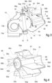
- An air distribution means 50 are interposed between the mixing section and the air outlets 38a-38c of the heating and/or air conditioning device. Said distribution means 50 are shown in detail in Figures 4 and 5 .
- the air distribution means comprise a cross-shaped housing 51 fastened to the box 10 of the air conditioning device, at or immediately downstream of the mixing zone 34.
- the housing 51 may be made, at least in part, in one piece with a portion of the box 10 wherein the mixing zone 34 is formed.
- the housing 51 is made as a shell comprising a top wall 52 and a plurality of lateral walls 53a, 53b, 53c, 53d projecting from the peripheral edge of the top wall 52. On the side opposite the top wall 52 the housing 51 is open and configured to be coupled to a wall 10' of the box 10.
- the housing 51 defines therein a circular chamber 51a wherefrom four ducts 54a, 54b, 54c, 54d extend in the radial direction, laterally delimited by the lateral walls 53a, 53b, 53c, 53d of the housing 51.
- the lateral walls 53a, 53b, 53c, 53d of the housing 51 have a respective apical portion extending in an arc of circumference and arranged at the perimeter of the circular chamber 51a.
- the housing 51 thus defines a first distribution inlet 55a, a second distribution inlet 55b and a pair of distribution outlets 55c, 55d, all facing the circular chamber 51a and interspersed with the aforesaid apical portions of the lateral walls 53a, 53b, 53c, 53d of the housing 51.
- the duct 54a enters the circular chamber 51a through the first distribution inlet 55a, while the duct 54b enters the circular chamber 51a through the second distribution inlet 55b.
- the ducts 54c and 54d branch off from the circular chamber 51a through the respective distribution outlets 55c and 55d.
- Each of the distribution outlets 55c, 55d is placed in front of a respective distribution inlet 55a, 55b.
- the first distribution inlet 55a and the second distribution inlet 55b are connected to the air transmitting branch 26 and the air heating branch 28 through the respective ducts 54a and 54b, respectively.
- the distribution outlets 55c and 55d are connected to the air outlets 38a-38c of the heating and/or air conditioning device through the respective ducts 54c and 54d.
- the distribution outlet 55c and the relative duct 54c are connected to the footwell heating outlet 38b, while the distribution outlet 55d and the relative duct 54d are connected to the other outlets 38a and 38c.
- the shape of the housing 51 is such to make a coupling with the corresponding passages obtained in the box 10 of the air conditioning device, and in particular with the air transmitting branch 26, with the air heating branch 28, and with the passages leading to the various air outlets 38a-38c.
- Such coupling may relate to only one part or to the entire extension of such ducts in the direction of height (direction orthogonal to the plane of the drawings in Figures 1, 2 and 3 ).
- the housing 51 covers the entire height extension of the aforesaid ducts, the air flows originating from the air transmitting branch 26 and the air heating branch 28 are entirely channeled into the housing 51, and the circular chamber 51a actually coincides with the mixing zone 34.
- the housing 51 covers only part of the height extension of the aforesaid ducts, only part of the air flows originating from the air transmitting branch 26 and the air heating branch 28 are channeled into the housing 51. The remaining part follows a parallel path from the mixing zone 34 to the air outlets 38a-38c, and is not involved in the adjustment imparted by the air distribution means 50.
- a drum door 56 is arranged rotatably mounted about an axis z orthogonal to the directions going from the first distribution inlet 54a to the distribution outlet 54c and from the second distribution inlet 54b to the distribution outlet 54d, respectively.
- the drum door 56 comprises at opposite ends respective pins 56a and 56b coupled to respective seats obtained on the top wall 52 of the housing 51 and on the wall 10' of the box 10.
- the pin 56b coupled to the wall 10' of the box 10 is configured to be connected to an actuator (not shown) for controlling the drum door 56.
- the drum door 56 has a body having circular symmetry about the axis z, through which a passage channel 57 is formed extending in the diametral direction.
- the width of the passage channel 57 at the lateral surface of the drum door 56 is equal to or less than the width of each of the distribution inlets 55a and 55b.
- the width of the passage channel 57 at the lateral surface of the drum door 56 is equal to or smaller than the width of each of the distribution outlets 55c and 55d.
- the drum door 56 is movable between a first position in which the passage channel 57 of the drum door 56 places the first distribution inlet 55a in communication with the distribution outlet 55c ( Figure 1 ), a second position in which the passage channel 57 of the drum door 56 places the second distribution inlet 55b in communication with the other distribution outlet 55d ( Figure 3 ), and at least one intermediate position in which the passage channel 57 of the drum door 56 places both distribution inlets 55a, 55b in communication with both of the distribution outlets 55c, 55d ( Figure 2 ).
- the passage channel 57 of the drum door 56 is aligned with the first distribution inlet 55a and with the distribution outlet 55c, while the portions of the drum door 56 that laterally delimit the passage channel 57 occlude the second distribution inlet 55b and the other distribution outlet 55d.
- the passage channel 57 of the drum door 56 is aligned with the second distribution inlet 55b and with the distribution outlet 55d, while the portions of the drum door 56 that laterally delimit the passage channel 57 occlude the first distribution inlet 55a and the other distribution outlet 55c.
- the passage channel 57 of the drum door 56 is aligned with the apical portions of the lateral walls 53c and 53a respectively arranged between the first distribution inlet 55a and the second distribution inlet 55b, and between the distribution outlets 55c and 55d. Since the width of such apical portions is less than the width of the passage channel 57, it is possible to ensure that air flows from both the air transmitting branch 26 and the air heating branch 28 may be simultaneously conveyed to the air outlets 38a-38c.
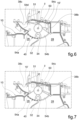
- Figure 6 shows a part of a heating and/or air conditioning device having a different configuration than that of Figures 1 and 3 . Elements corresponding to those of the preceding embodiment have been assigned the same numerical references; these elements will not be described again.
- the mixing means 40 shown schematically with a dashed line
- Figure 6 shows only the final part of the air transmitting 26 and air heating branches 28, in proximity to the mixing zone 34.
- the air distribution means 50 reference is made to the description of Figures 1-5 .
- FIG 7 shows a part of a heating and/or air conditioning device having the same configuration as in Figure 6 , wherein the air distribution means 50 are slightly different from that described above. Elements corresponding to those of the preceding embodiment have been assigned the same numerical references; these elements will not be described again.
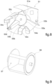
- the air distribution means 50 (also shown in Figures 8 and 9 ) comprise a Y-shaped housing 51.
- the housing 51 defines therein a circular chamber 51a wherefrom three ducts 54a, 54b, 54c, laterally delimited by the lateral walls 53b, 53c, 53d of the housing 51, extend in the radial direction.
- the lateral walls 53b, 53c, 53d of the housing 51 have a respective apical portion extending in an arc of circumference and arranged at the perimeter of the circular chamber 51a.
- the housing 51 defines a first distribution inlet 55a, a second distribution inlet 55b, and a distribution outlet 55c, all facing the circular chamber 51a and interspersed with the aforesaid apical portions of the lateral walls 53b, 53c, 53d of the housing 51.
- the duct 54a enters the circular chamber 51a through the first distribution inlet 55a, while the duct 54b enters the circular chamber 51a through the second distribution inlet 55b.
- the duct 54c departs from the circular chamber 51a through the distribution outlet 55c.
- the first distribution inlet 55a and the second distribution inlet 55b are connected to the air transmitting branch 26 and the air heating branch 28 through the respective ducts 54a and 54b, respectively.
- the distribution outlet 55c is connected to the air outlet 38b of the heating and/or air conditioning device through the duct 54c. As may be seen, there is no communication between the circular chamber 51a of the air distribution means 50 and the air outlets 38a and 38c of the heating and/or air conditioning device.
- the housing 51 covers only part of the height extension of the ducts 26 and 28. Only part of the air flows from the air transmitting branch 26 and the air heating branch 28 are therefore channeled into the housing 51. The remaining part follows a parallel path from the mixing zone 34 to the air outlets 38a-38c, and is not involved in the adjustment imparted by the air distribution means 50. Consequently, the air flows intended for the air outlets 38a and 38c are not involved in the regulation imparted by the air distribution means 50.
- the drum door 56 is arranged rotatably mounted about an axis z orthogonal to the directions going from the first distribution inlet 55a and from the second distribution inlet 55b to the distribution outlet 55c, respectively.
- the drum door 56 has a body having circular symmetry about the axis z, through which a passage channel 57 is formed extending in the diametral direction.
- the drum door 56 is movable between a first position in which the passage channel 57 of the drum door 56 puts the first distribution inlet 55a in communication with the distribution outlet 55c, a second position in which the passage channel 57 of the drum door 56 puts the second distribution inlet 55b in communication with the distribution outlet 55c, and at least one intermediate position in which the passage channel 57 of the drum door 56 puts both distribution inlets 55a, 55b in communication with the* distribution outlet 55c.
- the passage channel 57 of the drum door 56 is aligned with the first distribution inlet 55a and with the distribution outlet 55c, whilst a portion of the drum door 56 that laterally delimits the passage channel 57 occludes the second distribution inlet 55b.
- the passage channel 57 of the drum door 56 is aligned with the second distribution inlet 55b and with the distribution outlet 55c, whilst the portion of the drum door 56 that laterally delimits the passage channel 57 occludes the first distribution inlet 55a.
- the passage channel 57 of the drum door 56 is aligned with the apical portion of the side wall 53c arranged between the first distribution inlet 55a and the second distribution inlet 55b. Insofar as the width of this apical portion is less than the width of the passage channel 57, it is possible to ensure that air flows originating from both the air transmitting branch 26 and the air heating branch 28 may be simultaneously conveyed to the air outlet 38b.
- the door 56 may be a rotatable door of a different type than a drum door, such as a tilting or butterfly door.
- the chamber 51a should be adapted to the type of shape and movement of the door.
- the air distribution means 50 comprise two inlet ducts 54a, 54b and one or two outlet ducts 54c, 54d. It is possible to hypothesize an air distribution means with more than two outlet ducts, but this would require a correspondingly large inner chamber 51a, and therefore a larger overall size of the air distribution means 50.
Landscapes
- Physics & Mathematics (AREA)
- Thermal Sciences (AREA)
- Engineering & Computer Science (AREA)
- Mechanical Engineering (AREA)
- Air-Conditioning For Vehicles (AREA)
Abstract
Description
- The present invention relates to a heating and/or air conditioning device for a motor vehicle, comprising
- a mixing section comprising an air transmitting branch and an air heating branch, both supplied by an air inlet and communicating with each other through a mixing zone, and mixing means configured to distribute an air flow between the air transmitting branch and the air heating branch, wherein said mixing means are movable between two extreme positions comprising a closure position in which the mixing means prevent the air inlet and the mixing zone from communicating with each other through the air heating branch, and force the air flow to pass through the air transmitting branch, and an opening position in which the mixing means prevent the air inlet and the mixing zone from communicating with each other through the air transmitting branch, and force the air flow to pass through the air heating branch;
- air distribution means interposed between the mixing section and a plurality of air outlets of the heating and/or air conditioning device.
- Devices of this type are known, wherein the mixing means comprise doors of different types, which are generally adapted to oscillate between two extreme positions, that is, an "all-hot" position and an "all-cold" position, and to occupy a plurality of intermediate positions. The treated air flow is generated by a fan located upstream of the air inlet.
- One object of the present invention is to provide a solution for improving the stratification of the air flow from the mixing area to the air outlets of the heating and/or air conditioning device.
- This object is achieved according to the invention by a device of the type defined above, wherein said air distribution means comprise a housing arranged at the mixing zone, wherein said housing defines a chamber and further defines a first distribution inlet and a second distribution inlet facing the chamber and connected with the air transmitting branch and the air heating branch, respectively, and at least one distribution outlet facing the chamber and connected with at least one of the air outlets of the heating and/or air conditioning device, and
- a door rotatably mounted in the chamber to control the distribution of the air flow between the distribution inlets and the at least one distribution outlet,
- wherein the door is movable among a first position in which the door puts the sole first distribution inlet in communication with the at least one distribution outlet, a second position in which the door puts the sole second distribution inlet in communication with the at least one distribution outlet, and at least one intermediate position in which the door puts both distribution inlets in communication with the at least one distribution outlet.
- By virtue of the rotatable door, it is possible to actively adjust the conveyance of the air flow from the mixing area to the various air outlets of the heating and/or air conditioning device, improving the stratification of the air flow.
- Preferred embodiments of the invention are defined in the dependent claims, which are to be understood as an integral part of the present description.
- Further features and advantages of the device according to the invention will become clearer from the following detailed description of an embodiment of the invention, made in reference to the accompanying drawings, provided purely for illustrative and non-limiting purposes, wherein:
-
Figure 1 is a schematic cross-sectional view of a heating and/or air conditioning device according to the invention, in the "all-cold" position, or closed position; -
Figure 2 is a similar view toFigure 1 , in an intermediate mixing position; -
Figure 3 is a similar view to the above, in the "all-hot" position, or open position; -
Figure 4 is a perspective view of a distribution means of the device inFigures 1-3 ; -
Figure 5 is a partial cross-sectional view of the distribution means ofFigure 4 mounted on a heating and/or air conditioning device having a configuration different to that ofFigures 1-3 ; -
Figure 6 is a partial cross-section view of a part of the heating and/or air conditioning device ofFigure 5 ; -
Figure 7 is a partially sectional view of the heating and/or air conditioning device ofFigure 6 , whereupon a different embodiment of the distribution means are mounted; and -
Figures 8 and 9 are perspective views of two components of the distribution means shown inFigure 7 . - The device depicted in the figures comprises a
housing 10 delimiting aninlet duct 12 adapted to be supplied by an air flow (arrow F1) driven by acentrifugal fan 13. Thecentrifugal fan 13 conventionally comprises anauger 13a and animpeller 13b housed in theauger 13a and driven by an electric motor (not shown). Thefan 13 is in turn powered by an outer air flow drawn from outside the vehicle's passenger compartment, or by a recirculating air stream drawn from inside the passenger compartment. - An evaporator E may be transversely housed in the
inlet duct 12 connected to a conventional air conditioning circuit so as to produce an outflow of air that may be conditioned if the evaporator is active. - Downstream, the
inlet duct 12 emerges into a part of the air conditioning device dedicated to mixing hot and cold air veins. At the inlet of such mixing section, the inlet duct therefore defines anair inlet 14 bounded byopposing walls housing 10. - The
air inlet 14 defines a confluence zone that supplies anair transmitting branch 26 on one side, and anair heating branch 28 on the other side. Theair heating branch 28 is delimited externally by acurved wall 30 of thehousing 10 and internally by aninner partition 32. On the other hand, thetransmitting branch 26 is delimited internally by theinner partition 32, and externally by an extension of thewall 16. Thebranches air inlet 14, and on the other hand at the level of anotherconfluence zone 34, arranged downstream, which in the following will be referred to as the mixing zone. - One or
more heating elements heating branch 28. - The
mixing zone 34 conventionally communicates with various air distribution ducts that are used to distribute the treated air to various areas within the vehicle. For example, air outlets 37a may be envisaged which are configured to be connected to vents used for the defrosting/defogging of the windshield of a motor vehicle,air outlets 38a may be configured to be connected to vents arranged in the lower part of the passenger compartment of the motor vehicle (foot heating),air outlets 38c may be configured to be connected to vents provided on the dashboard of the motor vehicle, and so on. - Mixing means 40 are mounted in the
box 10, at the mixing section of the air conditioning device. - In the example shown, the mixing means 40 are arranged between the
air inlet 14 and the air transmitting andair heating branches Figures 6 and 7 ), the mixing means 40 could be arranged at themixing zone 34. - The construction and the type of movement of the mixing means 40 are not essential for the purposes of the invention.
- The mixing means 40 are adapted to oscillate between two extreme positions:
- a closed or "all-cold" position (shown by a dashed line in
Figure 1 ), wherein the mixing means 40 prevent communication between theair inlet 14 and theair heating branch 28 and force the air flow to pass through theair transmitting branch 26, as indicated by the arrow F2. - an open or "all-hot" position (shown by a dashed line in
Figure 3 ), wherein the mixing means 40 prevent communication between theair inlet 14 and theair transmitting branch 26 and forces the air flow to pass through theair heating branch 28, as indicated by the arrow F3. -
Figure 2 shows an intermediate position of the mixing means 40. - An air distribution means 50 are interposed between the mixing section and the
air outlets 38a-38c of the heating and/or air conditioning device. Said distribution means 50 are shown in detail inFigures 4 and5 . - The air distribution means comprise a
cross-shaped housing 51 fastened to thebox 10 of the air conditioning device, at or immediately downstream of themixing zone 34. According to alternative embodiments which are not shown, thehousing 51 may be made, at least in part, in one piece with a portion of thebox 10 wherein themixing zone 34 is formed. - The
housing 51 is made as a shell comprising atop wall 52 and a plurality oflateral walls top wall 52. On the side opposite thetop wall 52 thehousing 51 is open and configured to be coupled to a wall 10' of thebox 10. - In cooperation with this wall 10', the
housing 51 defines therein acircular chamber 51a wherefrom fourducts lateral walls housing 51. At the confluence of each pair of ducts, thelateral walls housing 51 have a respective apical portion extending in an arc of circumference and arranged at the perimeter of thecircular chamber 51a. Thehousing 51 thus defines afirst distribution inlet 55a, asecond distribution inlet 55b and a pair ofdistribution outlets circular chamber 51a and interspersed with the aforesaid apical portions of thelateral walls housing 51. Theduct 54a enters thecircular chamber 51a through thefirst distribution inlet 55a, while theduct 54b enters thecircular chamber 51a through thesecond distribution inlet 55b. Theducts circular chamber 51a through therespective distribution outlets distribution outlets respective distribution inlet - The
first distribution inlet 55a and thesecond distribution inlet 55b are connected to theair transmitting branch 26 and theair heating branch 28 through therespective ducts distribution outlets air outlets 38a-38c of the heating and/or air conditioning device through therespective ducts distribution outlet 55c and therelative duct 54c are connected to thefootwell heating outlet 38b, while thedistribution outlet 55d and therelative duct 54d are connected to theother outlets housing 51 is such to make a coupling with the corresponding passages obtained in thebox 10 of the air conditioning device, and in particular with theair transmitting branch 26, with theair heating branch 28, and with the passages leading to thevarious air outlets 38a-38c. Such coupling may relate to only one part or to the entire extension of such ducts in the direction of height (direction orthogonal to the plane of the drawings inFigures 1, 2 and3 ). In the event that thehousing 51 covers the entire height extension of the aforesaid ducts, the air flows originating from theair transmitting branch 26 and theair heating branch 28 are entirely channeled into thehousing 51, and thecircular chamber 51a actually coincides with themixing zone 34. In the event that thehousing 51 covers only part of the height extension of the aforesaid ducts, only part of the air flows originating from theair transmitting branch 26 and theair heating branch 28 are channeled into thehousing 51. The remaining part follows a parallel path from themixing zone 34 to theair outlets 38a-38c, and is not involved in the adjustment imparted by the air distribution means 50. - Inside the
circular chamber 51a adrum door 56 is arranged rotatably mounted about an axis z orthogonal to the directions going from thefirst distribution inlet 54a to thedistribution outlet 54c and from thesecond distribution inlet 54b to thedistribution outlet 54d, respectively. In the example shown, thedrum door 56 comprises at opposite endsrespective pins top wall 52 of thehousing 51 and on the wall 10' of thebox 10. In particular, thepin 56b coupled to the wall 10' of thebox 10 is configured to be connected to an actuator (not shown) for controlling thedrum door 56. - The
drum door 56 has a body having circular symmetry about the axis z, through which apassage channel 57 is formed extending in the diametral direction. Preferably, the width of thepassage channel 57 at the lateral surface of thedrum door 56 is equal to or less than the width of each of thedistribution inlets passage channel 57 at the lateral surface of thedrum door 56 is equal to or smaller than the width of each of thedistribution outlets - The
drum door 56 is movable between a first position in which thepassage channel 57 of thedrum door 56 places thefirst distribution inlet 55a in communication with thedistribution outlet 55c (Figure 1 ), a second position in which thepassage channel 57 of thedrum door 56 places thesecond distribution inlet 55b in communication with theother distribution outlet 55d (Figure 3 ), and at least one intermediate position in which thepassage channel 57 of thedrum door 56 places bothdistribution inlets distribution outlets Figure 2 ). - In the first position (
Figure 1 ), thepassage channel 57 of thedrum door 56 is aligned with thefirst distribution inlet 55a and with thedistribution outlet 55c, while the portions of thedrum door 56 that laterally delimit thepassage channel 57 occlude thesecond distribution inlet 55b and theother distribution outlet 55d. In the second position (Figure 3 ), thepassage channel 57 of thedrum door 56 is aligned with thesecond distribution inlet 55b and with thedistribution outlet 55d, while the portions of thedrum door 56 that laterally delimit thepassage channel 57 occlude thefirst distribution inlet 55a and theother distribution outlet 55c. In the third position (Figure 2 ), thepassage channel 57 of thedrum door 56 is aligned with the apical portions of thelateral walls first distribution inlet 55a and thesecond distribution inlet 55b, and between thedistribution outlets passage channel 57, it is possible to ensure that air flows from both theair transmitting branch 26 and theair heating branch 28 may be simultaneously conveyed to theair outlets 38a-38c. - For simplicity, in
Figure 1 the air distribution means 50 have been represented in the first position, with the mixing means 40 in the closed position, inFigure 2 the air distribution means 50 have been represented in the intermediate position, with the mixing means 40 in the intermediate position, and inFigure 3 the air distribution means 50 have been represented in the second position, with the mixing means 40 in the open position. It is however understood that there is no such unambiguous relationship between the position of the air distribution means 50 and the position of the mixing means 40; the air distribution means 50 may therefore be adjusted in the different positions thereof for each of the positions of the mixingmember 40. While, in general, the position of the mixing means 40 is established by a control device of the air conditioning device based upon a temperature setting entered by the user, the position of the air distribution means 50 is established automatically by the control device based upon operating protocols defined by the manufacturer. - By virtue of the arrangement described above, it is possible to actively regulate the conveyance of the air flow from the mixing area to the various air outlets of the heating and/or air conditioning device thereby improving the stratification of the air.
-
Figure 6 shows a part of a heating and/or air conditioning device having a different configuration than that ofFigures 1 and3 . Elements corresponding to those of the preceding embodiment have been assigned the same numerical references; these elements will not be described again. In essence, in such a heating and/or air conditioning device the mixing means 40 (shown schematically with a dashed line) are arranged at the mixingzone 34, with the air distribution means 50 arranged immediately downstream of the mixing means 40. Therefore,Figure 6 shows only the final part of the air transmitting 26 andair heating branches 28, in proximity to the mixingzone 34. For a description of the air distribution means 50, reference is made to the description ofFigures 1-5 . -
Figure 7 shows a part of a heating and/or air conditioning device having the same configuration as inFigure 6 , wherein the air distribution means 50 are slightly different from that described above. Elements corresponding to those of the preceding embodiment have been assigned the same numerical references; these elements will not be described again. In essence, the air distribution means 50 (also shown inFigures 8 and 9 ) comprise a Y-shapedhousing 51. In cooperation with the wall 10', thehousing 51 defines therein acircular chamber 51a wherefrom threeducts lateral walls housing 51, extend in the radial direction. At the confluence of each pair of ducts, thelateral walls housing 51 have a respective apical portion extending in an arc of circumference and arranged at the perimeter of thecircular chamber 51a. Thus, thehousing 51 defines afirst distribution inlet 55a, asecond distribution inlet 55b, and adistribution outlet 55c, all facing thecircular chamber 51a and interspersed with the aforesaid apical portions of thelateral walls housing 51. Theduct 54a enters thecircular chamber 51a through thefirst distribution inlet 55a, while theduct 54b enters thecircular chamber 51a through thesecond distribution inlet 55b. Theduct 54c departs from thecircular chamber 51a through thedistribution outlet 55c. - The
first distribution inlet 55a and thesecond distribution inlet 55b are connected to theair transmitting branch 26 and theair heating branch 28 through therespective ducts distribution outlet 55c is connected to theair outlet 38b of the heating and/or air conditioning device through theduct 54c. As may be seen, there is no communication between thecircular chamber 51a of the air distribution means 50 and theair outlets - The
housing 51 covers only part of the height extension of theducts air transmitting branch 26 and theair heating branch 28 are therefore channeled into thehousing 51. The remaining part follows a parallel path from the mixingzone 34 to theair outlets 38a-38c, and is not involved in the adjustment imparted by the air distribution means 50. Consequently, the air flows intended for theair outlets - Inside the
circular chamber 51a thedrum door 56 is arranged rotatably mounted about an axis z orthogonal to the directions going from thefirst distribution inlet 55a and from thesecond distribution inlet 55b to thedistribution outlet 55c, respectively. - The
drum door 56 has a body having circular symmetry about the axis z, through which apassage channel 57 is formed extending in the diametral direction. - The
drum door 56 is movable between a first position in which thepassage channel 57 of thedrum door 56 puts thefirst distribution inlet 55a in communication with thedistribution outlet 55c, a second position in which thepassage channel 57 of thedrum door 56 puts thesecond distribution inlet 55b in communication with thedistribution outlet 55c, and at least one intermediate position in which thepassage channel 57 of thedrum door 56 puts bothdistribution inlets distribution outlet 55c. - In the first position, the
passage channel 57 of thedrum door 56 is aligned with thefirst distribution inlet 55a and with thedistribution outlet 55c, whilst a portion of thedrum door 56 that laterally delimits thepassage channel 57 occludes thesecond distribution inlet 55b. In the second position, thepassage channel 57 of thedrum door 56 is aligned with thesecond distribution inlet 55b and with thedistribution outlet 55c, whilst the portion of thedrum door 56 that laterally delimits thepassage channel 57 occludes thefirst distribution inlet 55a. In the third position (Figure 2 ), thepassage channel 57 of thedrum door 56 is aligned with the apical portion of theside wall 53c arranged between thefirst distribution inlet 55a and thesecond distribution inlet 55b. Insofar as the width of this apical portion is less than the width of thepassage channel 57, it is possible to ensure that air flows originating from both theair transmitting branch 26 and theair heating branch 28 may be simultaneously conveyed to theair outlet 38b. - It should be noted that, in the embodiment of
Figures 7-9 , thedoor 56 may be a rotatable door of a different type than a drum door, such as a tilting or butterfly door. In this case, thechamber 51a should be adapted to the type of shape and movement of the door. In any case, it is essential for the door to be movable between a first position wherein the door puts only thefirst distribution inlet 55a in communication with thedistribution outlet 55c, a second position in which the door puts only thesecond distribution inlet 55b in communication with thedistribution outlet 55c, and at least one intermediate position in which the door puts bothdistribution inlets distribution outlet 55c. - In the examples described above, the air distribution means 50 comprise two
inlet ducts outlet ducts inner chamber 51a, and therefore a larger overall size of the air distribution means 50.
Claims (6)
- Heating and/or air conditioning device for a motor vehicle, comprisinga mixing section comprising an air transmitting branch (26) and an air heating branch (28), both supplied by an air inlet (14) and communicating with each other through a mixing zone (34), and mixing means (40) configured to distribute an air flow between the air transmitting branch (26) and the air heating branch (28), wherein said mixing means (40) are movable between two extreme positions comprising a closure position in which the mixing means prevent the air inlet (14) and the mixing zone (34) from communicating with each other through the air heating branch (28), and force the air flow to pass through the air transmitting branch (26), and an opening position in which the mixing means prevent the air inlet (14) and the mixing zone (34) from communicating with each other through the air transmitting branch (26), and force the air flow to pass through the air heating branch (28);air distributing means (50) interposed between the mixing section and a plurality of air outlets (38a, 38b, 38c) of the heating and/or air conditioning device;characterized in that said air distributing means (50) comprise a housing (51) arranged at the mixing zone (34), wherein said housing defines a chamber (51a), and further defines a first distribution inlet (55a) and a second distribution inlet (55b) facing the chamber (51a) and connected with the air transmitting branch (26) and the air heating branch (28), respectively, and at least one distribution outlet (55c, 55d) facing the chamber (51a) and connected with at least one of the air outlets (38a, 38b, 38c) of the heating and/or air conditioning device, anda door (56) rotatably mounted in the chamber (51a) to control the distribution of the air flow between the distribution inlets (55a, 55b) and the at least one distribution outlet (55c, 55d),wherein the door (56) is movable among a first position in which the door (56) puts the sole first distribution inlet (55a) in communication with the at least one distribution outlet (55c), a second position in which the door (56) puts the sole second distribution inlet (55b) in communication with the at least one distribution outlet (55c, 55d), and at least one intermediate position in which the door (56) puts both distribution inlets (55a, 55b) in communication with the at least one distribution outlet (55c, 55d).
- Device according to claim 1, wherein the housing (51) defines a plurality of conduits (54a, 54b, 54c, 54d) radially extending from the chamber (51a), each conduit being connected to one of said distribution inlets and at least one distribution outlet (55a, 55b, 55c, 55d), respectively.
- Device according to any of the preceding claims, wherein the housing (51) is formed as a shell comprising a top wall (52) and a plurality of lateral walls (53a, 53b, 53c, 53d) projecting from a peripheral edge of the top wall (52), wherein on a side opposite to the top wall (52) the housing (51) is coupled to a wall (10') of a box (10) of the heating and/or air conditioning device.
- Device according to claim 3, wherein the door (56) is coupled for rotation, on opposite ends thereof, to the top wall (52) of the housing (51) and to the wall (10') of the box (10), respectively.
- Device according to any of the preceding claims, wherein the chamber (51a) is circular and the door (56) is a drum door rotatably mounted in the chamber (51a), a passage channel (57) being formed through said drum door.
- Device according to claim 5, wherein the passage channel (57) has a width at a lateral surface of the drum door (56) equal to or smaller than the width of each of the distribution inlets (55a, 55b).
Applications Claiming Priority (1)
| Application Number | Priority Date | Filing Date | Title |
|---|---|---|---|
| IT202300010914 | 2023-05-30 |
Publications (3)
| Publication Number | Publication Date |
|---|---|
| EP4470808A1 true EP4470808A1 (en) | 2024-12-04 |
| EP4470808B1 EP4470808B1 (en) | 2026-02-25 |
| EP4470808C0 EP4470808C0 (en) | 2026-02-25 |
Family
ID=88098107
Family Applications (1)
| Application Number | Title | Priority Date | Filing Date |
|---|---|---|---|
| EP24178373.7A Active EP4470808B1 (en) | 2023-05-30 | 2024-05-28 | Heating and/or air conditioning device for a motor vehicle |
Country Status (2)
| Country | Link |
|---|---|
| EP (1) | EP4470808B1 (en) |
| ES (1) | ES3066709T3 (en) |
Citations (2)
| Publication number | Priority date | Publication date | Assignee | Title |
|---|---|---|---|---|
| DE4023306A1 (en) * | 1990-07-21 | 1992-01-23 | Bayerische Motoren Werke Ag | Controllable air mixer unit - has hollow rotatable drum with variable width aperture in its periphery into which at least two separate air streams feed |
| JP2003211937A (en) * | 2001-11-15 | 2003-07-30 | Calsonic Kansei Corp | Air distribution device for vehicle air conditioner and air conditioner for vehicle |
-
2024
- 2024-05-28 ES ES24178373T patent/ES3066709T3/en active Active
- 2024-05-28 EP EP24178373.7A patent/EP4470808B1/en active Active
Patent Citations (2)
| Publication number | Priority date | Publication date | Assignee | Title |
|---|---|---|---|---|
| DE4023306A1 (en) * | 1990-07-21 | 1992-01-23 | Bayerische Motoren Werke Ag | Controllable air mixer unit - has hollow rotatable drum with variable width aperture in its periphery into which at least two separate air streams feed |
| JP2003211937A (en) * | 2001-11-15 | 2003-07-30 | Calsonic Kansei Corp | Air distribution device for vehicle air conditioner and air conditioner for vehicle |
Also Published As
| Publication number | Publication date |
|---|---|
| EP4470808B1 (en) | 2026-02-25 |
| ES3066709T3 (en) | 2026-05-14 |
| EP4470808C0 (en) | 2026-02-25 |
Similar Documents
| Publication | Publication Date | Title |
|---|---|---|
| US6491578B2 (en) | Vehicle air conditioner having air suction port for each seat | |
| EP2460675B1 (en) | Integrated Front and Rear HVAC System | |
| KR20080026056A (en) | Method for adjusting the distribution flap and the corresponding distribution flap, in particular in the air duct housing for the automotive air conditioning system | |
| US5101883A (en) | Method of assembly of single and multi-zone vehicle heating and a/c systems | |
| JP2002154315A (en) | Automotive air conditioner with two mixing zones | |
| US6093096A (en) | Air conditioning apparatus for a rear seat of vehicle | |
| KR101403440B1 (en) | Air conditioner for vehicle | |
| JP4016496B2 (en) | Air conditioner for vehicles | |
| EP1564047B1 (en) | Automotive air-conditioning system | |
| CN103847462B (en) | The rear portion air-conditioning of vehicle | |
| KR101758722B1 (en) | Air conditioner for vehicle | |
| US10688970B2 (en) | Method of distributing air ventilation in a vehicle | |
| EP4470808B1 (en) | Heating and/or air conditioning device for a motor vehicle | |
| KR20200051539A (en) | Air conditioning system including internal gear linkage | |
| KR20160104763A (en) | Air conditioner for vehicle | |
| JP2003520731A (en) | Automotive air conditioner with separate treatment for the rear of the occupant compartment | |
| EP4566854A1 (en) | Heating and/or air-conditioning device for a motor vehicle | |
| JP3675161B2 (en) | Vehicle seat air conditioner | |
| EP3636470B1 (en) | Air-conditioning device for a vehicle comprising an articulated flap | |
| JP5243674B2 (en) | Vehicle air distribution device | |
| US12103358B2 (en) | Vehicle air conditioner | |
| KR101403436B1 (en) | Air conditioner for vehicle | |
| JP4742255B2 (en) | Air conditioner for vehicles | |
| KR101714469B1 (en) | Air conditioner for vehicle | |
| KR101450634B1 (en) | Dual zone type air conditioner for vehicle |
Legal Events
| Date | Code | Title | Description |
|---|---|---|---|
| PUAI | Public reference made under article 153(3) epc to a published international application that has entered the european phase |
Free format text: ORIGINAL CODE: 0009012 |
|
| STAA | Information on the status of an ep patent application or granted ep patent |
Free format text: STATUS: THE APPLICATION HAS BEEN PUBLISHED |
|
| AK | Designated contracting states |
Kind code of ref document: A1 Designated state(s): AL AT BE BG CH CY CZ DE DK EE ES FI FR GB GR HR HU IE IS IT LI LT LU LV MC ME MK MT NL NO PL PT RO RS SE SI SK SM TR |
|
| STAA | Information on the status of an ep patent application or granted ep patent |
Free format text: STATUS: REQUEST FOR EXAMINATION WAS MADE |
|
| 17P | Request for examination filed |
Effective date: 20250515 |
|
| GRAP | Despatch of communication of intention to grant a patent |
Free format text: ORIGINAL CODE: EPIDOSNIGR1 |
|
| STAA | Information on the status of an ep patent application or granted ep patent |
Free format text: STATUS: GRANT OF PATENT IS INTENDED |
|
| RIC1 | Information provided on ipc code assigned before grant |
Ipc: B60H 1/00 20060101AFI20250901BHEP |
|
| INTG | Intention to grant announced |
Effective date: 20250918 |
|
| GRAS | Grant fee paid |
Free format text: ORIGINAL CODE: EPIDOSNIGR3 |
|
| GRAA | (expected) grant |
Free format text: ORIGINAL CODE: 0009210 |
|
| STAA | Information on the status of an ep patent application or granted ep patent |
Free format text: STATUS: THE PATENT HAS BEEN GRANTED |
|
| AK | Designated contracting states |
Kind code of ref document: B1 Designated state(s): AL AT BE BG CH CY CZ DE DK EE ES FI FR GB GR HR HU IE IS IT LI LT LU LV MC ME MK MT NL NO PL PT RO RS SE SI SK SM TR |
|
| REG | Reference to a national code |
Ref country code: CH Ref legal event code: F10 Free format text: ST27 STATUS EVENT CODE: U-0-0-F10-F00 (AS PROVIDED BY THE NATIONAL OFFICE) Effective date: 20260225 Ref country code: GB Ref legal event code: FG4D |
|
| REG | Reference to a national code |
Ref country code: DE Ref legal event code: R096 Ref document number: 602024002758 Country of ref document: DE |
|
| REG | Reference to a national code |
Ref country code: IE Ref legal event code: FG4D |
|
| U01 | Request for unitary effect filed |
Effective date: 20260310 |
|
| U07 | Unitary effect registered |
Designated state(s): AT BE BG DE DK EE FI FR IT LT LU LV MT NL PT RO SE SI Effective date: 20260316 |
|
| REG | Reference to a national code |
Ref country code: ES Ref legal event code: FG2A Ref document number: 3066709 Country of ref document: ES Kind code of ref document: T3 Effective date: 20260514 |
|
| U20 | Renewal fee for the european patent with unitary effect paid |
Year of fee payment: 3 Effective date: 20260519 |
|
| PG25 | Lapsed in a contracting state [announced via postgrant information from national office to epo] |
Ref country code: RS Free format text: LAPSE BECAUSE OF FAILURE TO SUBMIT A TRANSLATION OF THE DESCRIPTION OR TO PAY THE FEE WITHIN THE PRESCRIBED TIME-LIMIT Effective date: 20260525 |
|
| PGFP | Annual fee paid to national office [announced via postgrant information from national office to epo] |
Ref country code: ES Payment date: 20260601 Year of fee payment: 3 |
|
| PG25 | Lapsed in a contracting state [announced via postgrant information from national office to epo] |
Ref country code: PL Free format text: LAPSE BECAUSE OF FAILURE TO SUBMIT A TRANSLATION OF THE DESCRIPTION OR TO PAY THE FEE WITHIN THE PRESCRIBED TIME-LIMIT Effective date: 20260225 |
|
| PG25 | Lapsed in a contracting state [announced via postgrant information from national office to epo] |
Ref country code: GR Free format text: LAPSE BECAUSE OF FAILURE TO SUBMIT A TRANSLATION OF THE DESCRIPTION OR TO PAY THE FEE WITHIN THE PRESCRIBED TIME-LIMIT Effective date: 20260526 |
|
| PG25 | Lapsed in a contracting state [announced via postgrant information from national office to epo] |
Ref country code: NO Free format text: LAPSE BECAUSE OF FAILURE TO SUBMIT A TRANSLATION OF THE DESCRIPTION OR TO PAY THE FEE WITHIN THE PRESCRIBED TIME-LIMIT Effective date: 20260525 |
|
| PG25 | Lapsed in a contracting state [announced via postgrant information from national office to epo] |
Ref country code: HR Free format text: LAPSE BECAUSE OF FAILURE TO SUBMIT A TRANSLATION OF THE DESCRIPTION OR TO PAY THE FEE WITHIN THE PRESCRIBED TIME-LIMIT Effective date: 20260225 |
|
| PG25 | Lapsed in a contracting state [announced via postgrant information from national office to epo] |
Ref country code: IS Free format text: LAPSE BECAUSE OF FAILURE TO SUBMIT A TRANSLATION OF THE DESCRIPTION OR TO PAY THE FEE WITHIN THE PRESCRIBED TIME-LIMIT Effective date: 20260625 |
|
| PGFP | Annual fee paid to national office [announced via postgrant information from national office to epo] |
Ref country code: TR Payment date: 20260501 Year of fee payment: 3 |