EP4470733A1 - Spiralförmiger schleifenartiger greifer und übertragungsmittel damit - Google Patents
Spiralförmiger schleifenartiger greifer und übertragungsmittel damit Download PDFInfo
- Publication number
- EP4470733A1 EP4470733A1 EP23747374.9A EP23747374A EP4470733A1 EP 4470733 A1 EP4470733 A1 EP 4470733A1 EP 23747374 A EP23747374 A EP 23747374A EP 4470733 A1 EP4470733 A1 EP 4470733A1
- Authority
- EP
- European Patent Office
- Prior art keywords
- plate
- gripper
- fixture
- loops
- loop
- Prior art date
- Legal status (The legal status is an assumption and is not a legal conclusion. Google has not performed a legal analysis and makes no representation as to the accuracy of the status listed.)
- Pending
Links
Images





Classifications
-
- B—PERFORMING OPERATIONS; TRANSPORTING
- B25—HAND TOOLS; PORTABLE POWER-DRIVEN TOOLS; MANIPULATORS
- B25J—MANIPULATORS; CHAMBERS PROVIDED WITH MANIPULATION DEVICES
- B25J15/00—Gripping heads and other end effectors
- B25J15/08—Gripping heads and other end effectors having finger members
- B25J15/10—Gripping heads and other end effectors having finger members with three or more finger members
-
- B—PERFORMING OPERATIONS; TRANSPORTING
- B25—HAND TOOLS; PORTABLE POWER-DRIVEN TOOLS; MANIPULATORS
- B25J—MANIPULATORS; CHAMBERS PROVIDED WITH MANIPULATION DEVICES
- B25J15/00—Gripping heads and other end effectors
- B25J15/02—Gripping heads and other end effectors servo-actuated
-
- B—PERFORMING OPERATIONS; TRANSPORTING
- B25—HAND TOOLS; PORTABLE POWER-DRIVEN TOOLS; MANIPULATORS
- B25J—MANIPULATORS; CHAMBERS PROVIDED WITH MANIPULATION DEVICES
- B25J15/00—Gripping heads and other end effectors
- B25J15/08—Gripping heads and other end effectors having finger members
- B25J15/12—Gripping heads and other end effectors having finger members with flexible finger members
Definitions
- the following disclosure relates to a gripper for gripping an object, an apparatus for conveyance with the gripper, and a gripping method, and more particularly, to a gripper gripping an object which may smoothly and stably lift a heavy object to prevent damage to the object, an apparatus for conveyance with the gripper, and a gripping method.
- a gripper engaging an object and an apparatus for conveyance which may lift the object from its current location and convey or transport the object to a destination may be required in order to move a location of the object.
- a representative example of the apparatus for conveyance may be a robot arm, a conveyor, or a hydraulic system which may extend a stroke, and the apparatus for conveyance may grip the object with the gripper, lift the object, move the object to a desired location, and then put the object down at the destination.
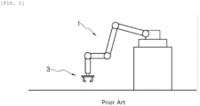
- FIG. 1 is a conceptual diagram showing a gripper mounted on a distal end of a robot arm according to the prior art
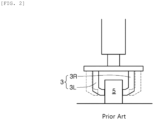
- FIG. 2 is a conceptual diagram showing a relationship in which an object is pressed and then lifted by the gripper shown in FIG. 1
- a robot arm 1 may be designed to have a multi-joint structure to move an object 5 within a usable range of the robot arm 1.
- a gripper 3 may be mounted on a distal end of the robot arm 1, and the gripper 3 may press a side of the object 5 to grip the object 5.
- a force (hereinafter referred to as 'grip force') exerted by the gripper 3 on the side of the object 5 is required to be greater than a load of the object 5. The reason is that it is required to prevent the object 5 from slipping off the gripper 3 when moved by an operation of the robot arm 1.
- an actuator may also be required to have proportionally increased capacity to generate a large grip force, and in this case, the actuator may also be generally required to have increased weight and volume.
- a payload may be increased when the gripper is mounted on the robot arm or the conveyor, which is the apparatus for conveyance, and the apparatus for conveyance may thus also be required to have the proportionally increased capacity.
- FIG. 2 shows a process in which the gripper 3 grips the side of the object 5 having a vertical structure.
- a point where a left gripper 3L or a right gripper 3R comes into contact with the object 5 may be unstable when the object 5 has a concave or convex shape, the center of gravity of the object 5 may be changed in a process of lifting the object 5, and the object 5 may thus slip off.
- a gripper may convey the object by adsorbing the object by using a suction plate.
- the suction plate may need to be managed periodically to secure a suction power for the object, and components for maintaining the inside of the suction plate in a vacuum state, such as a vacuum pump or a compressor, may need to be provided outside the robot arm as separate essential components.
- the gripper with the suction plate may be applied only to a light object. In order to be applied to a heavy object, a large gripper with a large number of suction plates may need to be provided, thus increasing the capacity of the apparatus for conveyance.
- Embodiments of the present disclosure are directed to providing a gripper gripping an object which may smoothly grip and stably lift a heavy object to prevent damage to the object in such a manner that the object is gripped using a plurality of spiral loops and lifted by a vertical drag force, an apparatus for conveyance with the gripper, and a gripping method.
- a gripper whose one end is connected to a first fixture and the other end is connected to a second fixture, includes a plurality of twisted loops each having a predetermined curvature, wherein the plurality of loops gather or spread to grip or release the object based on relative rotation of the first fixture and the second fixture.
- the loop part may be moved toward the axis line and enter the space between the object and the ground or under the lateral protrusion of the object when the first fixture and the second fixture are rotated relative to each other to grip the object located inside the spreading-out loops.
- the loops may then be twisted together, thus stably gripping the object as the gap between the loops becomes narrow.
- the gripper may easily and stably grip even the atypical object as the loop part enters the space between the object and the ground or under the lateral protrusion of the object to grip the object.
- the gripper according to the present disclosure may require a smaller force to press the object compared to the conventional gripper, thus preventing the object from being damaged because the loop enters the space between the object and the ground or under the lateral protrusion of the object to lift and convey the object while gripping the object.
- the gripper according to the present disclosure may have a simple structure and a small weight, thus reducing the payload.
- the first fixture may be a plate-shaped first plate
- the second fixture may be a plate-shaped second plate
- one end of each of the plurality of loops may be coupled to the first plate or extended from the first plate
- the other end of each of the plurality of loops may be coupled to the second plate or extended from the second plate.
- a rotation shaft rotating the first plate or the second plate may be coupled to the first plate or the second plate.
- the first plate may be formed by stacking the one end of each of the plurality of loops on top of each other, and the second plate may be formed by stacking the other end of each of the plurality of loops on top of each other.
- a large gripper having a longer strap and a small gripper having a shorter strap may be disposed together.
- the gripper may further include an intermediate plate disposed between the first plate and the second plate, one end of the large gripper may be connected to the first plate, and the other end of the large gripper may be connected to the intermediate plate, one end of the small gripper may be connected to the first plate, and the other end of the small gripper may be connected to the second plate, and the large gripper and the small gripper may be controlled based on the relative rotation of the first plate, the intermediate plate, and the second plate.
- the intermediate plate and the second plate may be rotated together or separately rotated relative to each other.
- the first fixture may be a plate-shaped first plate, and the second fixture may be a cylindrical cylinder.
- a rotation shaft may be coupled to the first plate to rotate the first plate, or rotate the cylindrical cylinder.
- the loop may be a strap having a predetermined elasticity.
- the loop may have a predetermined width or a width gradually decreased or increased from one end to the other end, or a middle portion thereof may have a width greater or smaller than that of one end or the other end.
- the loop may be an arc-shaped strap bent with the predetermined curvature.
- the loop may include a reinforcing member formed therein and having greater rigidity than that of the strap.
- a gripping method for gripping an object by using a loop-type gripper wherein the gripper has one end connected to a first fixture and the other end connected to a second fixture, and includes a plurality of twisted loops each having a predetermined curvature, the plurality of loops gather together to grip the object when the first fixture and the second fixture are rotated relative to each other in one direction, and the plurality of loops each spread to release the object when the first fixture and the second fixture are rotated relative to each other in the other direction.
- the relative rotation may control a spread degree of the plurality of loops based on a size of the object to be gripped, or a gathering degree of the plurality of loops based on a grip force for gripping the object.
- an apparatus for conveyance includes: a gripper mounted on a distal end of the apparatus for conveyance, having one end connected to a first fixture and the other end connected to a second fixture, and including a plurality of twisted loops each having a predetermined curvature, and gripping or releasing the object by the plurality of loops that gather together or spread out based on relative rotation of the first fixture and the second fixture; and a motor rotating the first fixture or second fixture of the gripper.
- the first fixture may be a plate-shaped first plate
- the second fixture may be a plate-shaped second plate
- one end of each of the plurality of loops may be coupled to the first plate or extended from the first plate
- the other end of each of the plurality of loops may be coupled to the second plate or extended from the second plate.
- the apparatus for conveyance may further include a rotation shaft connected to the motor and rotating the first plate or the second plate.
- the first plate may be formed by stacking the one end of each of the plurality of loops on top of each other, and the second plate may be formed by stacking the other end of each of the plurality of loops on top of each other.
- the first fixture may be a plate-shaped first plate, and the second fixture may be a cylindrical cylinder.
- a rotation shaft of the motor may be connected to the first plate to rotate the first plate, or the motor may be connected to the cylindrical cylinder to rotate the cylindrical cylinder.
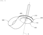
- FIG. 3 is a perspective view showing a gripper according to an embodiment of the present disclosure.
- the gripper according to the present disclosure may have one end connected to a first fixture 100 and the other end connected to a second fixture 200, and may include a plurality of twisted loops 300 each having a predetermined curvature.
- the plurality of loops 300 may gather together or spread out to grip or release an object based on relative rotation of the first fixture 100 and the second fixture 200.
- the middle portion of the loop 300 may be bent with the predetermined curvature as the first fixture 100 and the second fixture 200 are disposed to be adjacent to each other; the curvature of the middle portion of the loop 300 may be changed and the loop 300 may thus be twisted or untwisted, when the first fixture 100 and the second fixture 200 are rotated relative to each other; and accordingly, the object may be gripped or released from the grip.
- FIGS. 4 and 5 are views for explaining a process in which the gripper is closed to grip the object according to an embodiment of the present disclosure.
- the plurality of loops 300 may be twisted and gather together in a case where the relative rotation is performed in the gripper according to the present disclosure, i.e., when the second fixture 200 is rotated while the first fixture 100 is fixed, or the first fixture 100 is rotated while the second fixture 200 is fixed.
- the loops 300 may then be moved toward an axis line S to enter a space between the object and the ground or under a lateral protrusion of the object.
- the loops 300 may then be twisted together, thus gripping the object as a gap between the loops 300 becomes narrow.
- an angle ⁇ between both ends of the loops 300 and a rotation shaft 400 may be increased or decreased as the first fixture 100 and the second fixture 200 are rotated relative to each other. Accordingly, the longitudinal center of the loop 300 may become closer to or farther away from the axis line S.
- a process of gripping the object by using the gripper configured in this way may be performed as follows: The loops 300 may grip the object 5 as the loops 300 gather together toward the axis line S and enter the space between the object 5 and the ground or under the protrusion of the object 5. On the other hand, the object may be released from the grip as the loops 300 spread out by being moved outward under the object 5 while being farther away from the axis line S.
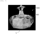
- FIG. 6 is a photograph showing a state where the gripper grips the object according to an embodiment of the present disclosure. It may be seen that transparent portions in the photograph are the loops 300 of the present disclosure, and the plurality of loops 300 may stably grip the object while being twisted together.
- the process of gripping the object 5 by the relative rotation of the first fixture 100 and the second fixture 200 may be described in more detail as follows:
- the loops may stably grip the object 5 as a strap 330 is moved toward the axis line S to enter the space between the object 5 and the ground or under the lateral protrusion of the object 5, and then twisted and tightened.
- the gripper according to the present disclosure may easily and stably grip even an atypical object whose shape is not specified as the thin strap 330 enters the space between the object 5 and the ground or under the lateral protrusion of the object to grip the object.
- the photograph of FIG. 6 shows the loop 300 made of a transparent material to effectively show the gripped object.
- the loop 300 may be made of various materials and shapes such as metal, synthetic resin, fiber, rubber, and paper, each of which is flexible and has a predetermined elasticity. A structure of the loop 300 is described in more detail below.
- the plurality of loops 300 may gather together to grip the object when the first fixture 100 and the second fixture 200 are rotated relative to each other in one direction as described above, and the plurality of loops 300 may each spread out to release the object when the first fixture 100 and the second fixture 200 are rotated relative to each other in the other direction.
- the relative rotation may be performed to control a spread degree of the plurality of loops 300 based on a size of the object to be gripped, and the relative rotation is performed to control a gathering degree of the plurality of loops 300 based on a grip force for gripping the object.
- FIG. 7 is a perspective view showing an example of shapes of the loop 300 and the fixture in the present disclosure.
- the first fixture 100 may be a plate-shaped first plate 110
- the second fixture 200 may be a plate-shaped second plate 210
- one end 310 of each of the plurality of loops may be coupled to the first plate 110 or extended from the first plate 110
- the other end 320 of each of the plurality of loops may be coupled to the second plate 210 or extended from the second plate 210.
- the gripper may include the first plate 110 and the second plate 210 rotated relative to each other, and the plurality of loops whose both ends are respectively extended or connected to the first plate 110 and the second plate 210, and the rotation shaft 400 rotating the first plate 110 or the second plate 210.
- the first plate 110 or the second plate 210 may be formed by stacking one end 310 or other end 320 of each of the plurality of loops on top of each other.
- one end 310 or the other end 320 of the stacked loops without a separate plate may serve as a plate.
- the loop 300 may have the belt-shaped strap 330, one end 310 of the loop that is formed at one end of the strap 330, and the other end 320 of the loop that is formed at the other end of the strap 330, which are integrally formed with one another.
- one end 310 of each of the plurality of loops 300 may be stacked on top of each other or the other end 320 of each of the loops may be stacked on top of each other in a regular pattern, and the first plate 110 may then be formed by fixing the stacked one end 310 of each of the loops on top of each other, and the second plate 210 may be formed by fixing the stacked other end 320 of each of the loops on top of each other.
- first plate 110, the second plate 210, and the loop part 300 may be separately configured from one another, and then also configured in such a way that one end of the loop 300 is fixedly connected to the first plate 110 and the other end of the loop 300 is fixedly connected to the second plate 210.
- a shaft hole may be formed in the center of the first plate 110, and the rotation shaft 400 fixed to the center of the second plate 210 may pass through the shaft hole.
- the gripper in an embodiment may include six loops 300, and in stacking the six loops 300, the loop stacked on the lowest layer may be referred to as a first loop, and the loops stacked thereon may be sequentially referred to as second to the sixth loops.
- the straps may be arranged for each of two ends of each strap to have an equal angle (e.g., 60 degrees), and for each plane of one end of each of the stacked loops to face upward while one end of each of the loops of the first to sixth loops are stacked and fixed by locating one end of loop of the second loop on top of one end of the loop of the first loop.
- each of the loops from the first to sixth loops may then also be sequentially stacked, and the assembled second plate 210 may be located on the first plate 110.
- the strap 330 may have a curvature, and the angle between each of the two ends of each strap 330 and the axis line S (e.g., 60 degrees) may be the same for all the six loops 300.
- one ends 310 and the other end 320 of each of the stacked loops may be disposed to face the same direction.
- the strap 330 may have a 180-degree twisted structure, through which a grip angle of the object, the grip force, or the like may also be adjusted.
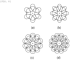
- FIGS. 8A to 8D are conceptual diagrams of various modifications in which the number of loops 300 is modified.
- the description describes the gripper above includes six loops 300 assembled to each other. However, more or fewer loops 300 of the gripper may be configured based on the size and weight of the object 5, and the angle ⁇ may be changed based on the number of loops 300.
- the minimum number of loops 300 may be two.
- various types of grippers may be configured by changing the number of spiral loops 300 or the width of the strap 330.
- FIG. 8A shows the gripper with six loops 300
- FIG. 8B shows the gripper with eight loops 300
- FIG. 8C shows the gripper with ten loops 300
- FIG. 8D shows the gripper with twelve loops 300.
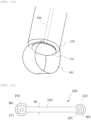
- FIG. 9 is a conceptual diagram of a modification including the plurality of grippers having different sizes.
- the grippers of different sizes may be simultaneously mounted by installing a small gripper 1000S inside a large gripper 1000L.
- the small gripper 1000S having a shorter strap 330S may be disposed inside the large gripper 1000L having a longer strap 330L.
- the lower drawing in FIG. 9 may be provided to schematically explain a disposition relationship between the large gripper 1000L and the small gripper 1000S along B-B'.
- An intermediate plate 120 may be disposed between the first plate 110 and the second plate 210.
- one end 310 of the loop of the large gripper 1000L having the long strap 330L may be coupled to the first plate 110, and the other end 320 of the loop of the large gripper 1000L may be coupled to the intermediate plate 120.
- one end 310 of the loop of the small gripper 1000S having the short strap 330S may be coupled to the first plate 110, and the other end 320 of the loop of the small gripper 1000S may be coupled to the second plate 210.
- grip conditions of the large gripper 1000L and small gripper 1000S may be controlled based on the relative rotation of the first plate 110, the intermediate plate 120, and the second plate while one end of the large gripper 1000L and one end of the small gripper 1000S are coupled together to the first plate 110.
- FIG. 10 is a perspective view showing another example of shapes of the loop 300 and the fixture 100 or 200 in the present disclosure.
- the first fixture 100 may be a plate-shaped first plate 110
- the second fixture 200 may be a cylindrical cylinder 220. That is, the other end 320 of the loop may be coupled to the inner or outer circumference of the cylindrical cylinder 220 or extended from one end of the cylindrical cylinder 220.
- the relative rotation may be performed at both the ends of the loop 300 when the rotation shaft 400 is coupled to the first plate 110 to rotate the first plate 110, through which the object may be gripped or released from the grip.
- the object may be gripped or released from the grip by performing the relative rotation at both the ends of the loop 300 even when the first plate 110 is fixed and the cylindrical cylinder 220 is rotated.
- FIG. 11 is a plan view showing another example of the loop 300 in the present disclosure.
- the loop 300 of the present disclosure may include the belt-shaped strap 330, one end 310 of the loop that is formed at one end of the strap 330, and the other end 320 of the loop that is formed at the other end of the strap 330.
- One end 310 of the loop and the other end 320 of the loop may each be a portion for fixing the strap 330 to the first fixture 100 or the second fixture 200, and have a polygonal or circular shape, and one end 310 of the loop and the other end 320 of the loop may each also have an area configured in various ways.
- the strap 330 may be made of a material having a predetermined elasticity, and required to be able to change its curvature or twist degree based on the relative rotation of the first fixture 100 and the second fixture 200.
- the overall length of the strap 330 may be a predetermined width W, or the width and shape of the strap 330 may be variously modified as shown in FIG. 12 .
- Shaft holes 311 and 321 may respectively be formed in the center of one end 310 of the loop and that of the other end 320 of the loop, and bolt holes BH may be formed along the circumference of each shaft hole.
- the bolt holes BH in one end 310 of each of the stacked loops may communicate with each other, and the first plate 110 may be formed by fastening nuts to bolts passing through the bolt holes BH.
- the second plate 210 may also be formed by fastening nuts to bolts passing through the bolt holes BH of the other end of each of the stacked loops 320.
- one end 310 of each of the stacked loops and the other end 320 of each of the loops may be attached and fixed to each other through adhesive and heat fusion.
- FIGS. 12A to 13 are views each showing another example of the loop 300 in the present disclosure.
- the strap 330 may have a width changed from one end 310 of the loop to the other end 320 of the loop. That is, the strap 330 may have a width gradually decreased from one end to the other end (W1 ⁇ W2) as shown in FIG. 12A , a middle portion of the strap 330 may have a width greater than that of one end 310 or the other end of the loop as shown in FIG. 12B , or the middle portion of the strap 330 may have a width smaller than that of one end 310 or the other end of the loop as shown in FIG. 12C .
- the strap 330 may be bent with the predetermined curvature as shown in FIG. 12D .
- FIG. 13 is a view showing another modification of the loop 300.
- the loop 300 may include a reinforcing member 340 formed therein and having greater rigidity than that of the strap 330. That is, as shown in a cross-sectional view of A-A' in FIG. 13 , the strap 330 may have a thin thickness by making the reinforcing member 340 located in the center of the strap 330 have the greater rigidity than that of the surrounding strap 330. In this way, it is possible to improve grip ability of the gripper by maintaining the overall rigidity of the strap 330 while making it easier for the gripper to be closer to the object for the grip.
- FIG. 14 is a conceptual diagram showing an example in which the gripper is mounted on a robot arm according to the present disclosure
- FIG. 15 is a conceptual diagram showing another example in which the gripper is mounted on the robot arm according to the present disclosure.
- the rotation shaft 400 may pass through the first plate 110 while the rotation shaft 400 is fixed to the center of the second plate 210.
- the second plate 210 may be rotated and the first plate 110 may be fixed to a distal end of a robot arm 1, the rotation shaft 400 may be rotated by a motor 500 mounted on the robot arm 1, and the gripper may grip or release the object 5 as the second plate 210 is rotated by the rotation of the rotation shaft 400.
- the robot arm 1 which is an apparatus for conveyance, may operate and lift the object 5 while the loops 300 of the gripper enter under the object 5 to grip the object 5.
- the object 5 may be lifted by a vertical drag force while spanning the loops 300.
- the object may be conveyed to a destination by the robot arm 1.
- the loops 300 may then spread out under the object 5 toward the outside of the object 5 when the first plate 110 and the second plate 210 are rotated relative to each other in the opposite directions, thereby releasing the object 5 from the grip.
- the rotation shaft 400 fixed to the second plate 210 may pass through the first plate 110 to be fixed to the distal end of the robot arm 1, and a pinion 420 mounted on the robot arm 1 may be coupled to a rack 410 fixed to the circumference of an upper surface of the first plate 110.
- the first plate 110 may be rotated while the rack 410 is moved as the pinion 420 is driven.
- FIGS. 14 and 15 conceptually show examples in each of which the gripper is installed on the robot arm 1 to explain an operational relationship of the gripper based on the relative rotation of the first plate 110 and the second plate 210 of the gripper according to the present disclosure, and the apparatus for conveyance is not limited to the robot arm 1.
- a driving method to configure the relative rotation of the first plate 110 and the second plate 210 may be variously changed, and the driving method of the first plate 110 and the second plate 210 is not limited to the configurations shown in FIGS. 14 and 15 .
- the present disclosure relates to a gripper for holding an object and a transport means including the same, and therefore has industrial applicability.
Landscapes
- Engineering & Computer Science (AREA)
- Robotics (AREA)
- Mechanical Engineering (AREA)
- Manipulator (AREA)
Applications Claiming Priority (2)
| Application Number | Priority Date | Filing Date | Title |
|---|---|---|---|
| KR1020220012547A KR102555319B1 (ko) | 2022-01-27 | 2022-01-27 | 스파이럴 루프형 그리퍼와 이를 구비한 이송수단 |
| PCT/KR2023/001252 WO2023146333A1 (ko) | 2022-01-27 | 2023-01-27 | 스파이럴 루프형 그리퍼와 이를 구비한 이송수단 |
Publications (2)
| Publication Number | Publication Date |
|---|---|
| EP4470733A1 true EP4470733A1 (de) | 2024-12-04 |
| EP4470733A4 EP4470733A4 (de) | 2025-12-10 |
Family
ID=87155508
Family Applications (1)
| Application Number | Title | Priority Date | Filing Date |
|---|---|---|---|
| EP23747374.9A Pending EP4470733A4 (de) | 2022-01-27 | 2023-01-27 | Spiralförmiger schleifenartiger greifer und übertragungsmittel damit |
Country Status (4)
| Country | Link |
|---|---|
| US (1) | US20230264371A1 (de) |
| EP (1) | EP4470733A4 (de) |
| KR (1) | KR102555319B1 (de) |
| WO (1) | WO2023146333A1 (de) |
Families Citing this family (3)
| Publication number | Priority date | Publication date | Assignee | Title |
|---|---|---|---|---|
| KR102908565B1 (ko) | 2023-11-09 | 2026-01-08 | 한국과학기술연구원 | 가변형 루프를 구비한 그리퍼 및 그 제어방법 |
| KR20250139162A (ko) | 2024-03-14 | 2025-09-23 | 한국과학기술원 | 릴 방식의 크기 변화가 가능한 나선 직조 그리퍼, 그의 제조 방법, 및 그를 갖는 장치 |
| KR102950964B1 (ko) | 2024-07-02 | 2026-04-13 | 한국과학기술연구원 | 가변형 와이어 그리퍼 및 그리퍼 시스템 |
Family Cites Families (9)
| Publication number | Priority date | Publication date | Assignee | Title |
|---|---|---|---|---|
| US7753918B2 (en) * | 2000-11-03 | 2010-07-13 | William A. Cook Australia Pty. Ltd. | Medical grasping device |
| WO2012148472A2 (en) | 2010-11-19 | 2012-11-01 | President And Fellows Of Harvard College | Soft robotic actuators |
| KR101444344B1 (ko) * | 2013-08-29 | 2014-09-26 | 삼성중공업 주식회사 | 케이블 그리퍼 및 이를 갖춘 케이블 포설장치 |
| KR101633658B1 (ko) * | 2014-09-12 | 2016-07-08 | 최병일 | 전동 그리핑 장치 |
| US10524810B2 (en) * | 2015-03-04 | 2020-01-07 | Gyrus Acmi, Inc. | Medical device for capturing stone fragments |
| CN108025443B (zh) | 2015-04-23 | 2019-07-23 | 软机器人公司 | 机器人抓持器以及机器人结构 |
| AR111057A1 (es) * | 2017-02-22 | 2019-05-29 | Zoetis Services Llc | Dispositivo de sujeción de huevos que tiene miembros entrelazados, y sistemas y métodos asociados |
| US10307913B2 (en) * | 2017-07-27 | 2019-06-04 | Control & Power Systems, Inc. | Robotic gripper |
| KR102195283B1 (ko) * | 2019-04-18 | 2020-12-28 | 공주대학교 산학협력단 | 나선형 마그네틱 로봇 |
-
2022
- 2022-01-27 KR KR1020220012547A patent/KR102555319B1/ko active Active
-
2023
- 2023-01-26 US US18/159,896 patent/US20230264371A1/en active Pending
- 2023-01-27 WO PCT/KR2023/001252 patent/WO2023146333A1/ko not_active Ceased
- 2023-01-27 EP EP23747374.9A patent/EP4470733A4/de active Pending
Also Published As
| Publication number | Publication date |
|---|---|
| US20230264371A1 (en) | 2023-08-24 |
| KR102555319B1 (ko) | 2023-07-14 |
| WO2023146333A1 (ko) | 2023-08-03 |
| EP4470733A4 (de) | 2025-12-10 |
Similar Documents
| Publication | Publication Date | Title |
|---|---|---|
| EP4470733A1 (de) | Spiralförmiger schleifenartiger greifer und übertragungsmittel damit | |
| US6382692B1 (en) | Vacuum gripper | |
| US6619432B1 (en) | Object transport apparatus, drive mechanism for object transport apparatus and method of using object transport apparatus | |
| CN107921716A (zh) | 用于生产飞机的纤维金属层压部件的方法 | |
| CN107472839A (zh) | 一种全向分配输送装置 | |
| CN110605703B (zh) | 一种六自由度末端可变形的并联绳牵引机构 | |
| CN1333177A (zh) | 安装分配工具及多带提升夹紧装置 | |
| WO1998051597A1 (en) | Conveyor with integrated self-actuating clamp | |
| EP1267091B1 (de) | Querelement mit einem konischen Halsabschnitt | |
| CN220164759U (zh) | 模块化锁站以及模块化锁站系统 | |
| JP2011079657A (ja) | 移載装置、移載方法 | |
| CN220351056U (zh) | 一种旋转移栽机构 | |
| US12128548B2 (en) | Soft grip unit, grip device comprising same, and driving method of grip device | |
| EP1437314B1 (de) | Verfahren und Vorrichtung zur automatischen Palletisierung von Gegenständen | |
| CN110654883A (zh) | 码垛装置 | |
| CN118753830A (zh) | 夹爪机构、电芯的堆叠方法、装置和电池包 | |
| CN214217385U (zh) | 抓手装置、抓钢机 | |
| TWI900666B (zh) | 物品升降裝置及具備物品升降裝置之物品搬送車 | |
| CN216888928U (zh) | 夹具及拆垛机构 | |
| CN103522293B (zh) | 机器人以及用于组装机器人的重构模块 | |
| CN114955576A (zh) | 一种基于3d视觉的码垛机器人及其末端执行器 | |
| CN115676584A (zh) | 储能集装箱吊装装置及系统 | |
| US12138779B2 (en) | Device for gripping a flat structure with openings in the area of its upper side | |
| KR20170075387A (ko) | 슬링 어셈블리 | |
| CN107324069A (zh) | 用于码垛机械手的夹紧装置 |
Legal Events
| Date | Code | Title | Description |
|---|---|---|---|
| STAA | Information on the status of an ep patent application or granted ep patent |
Free format text: STATUS: THE INTERNATIONAL PUBLICATION HAS BEEN MADE |
|
| PUAI | Public reference made under article 153(3) epc to a published international application that has entered the european phase |
Free format text: ORIGINAL CODE: 0009012 |
|
| STAA | Information on the status of an ep patent application or granted ep patent |
Free format text: STATUS: REQUEST FOR EXAMINATION WAS MADE |
|
| 17P | Request for examination filed |
Effective date: 20240812 |
|
| AK | Designated contracting states |
Kind code of ref document: A1 Designated state(s): AL AT BE BG CH CY CZ DE DK EE ES FI FR GB GR HR HU IE IS IT LI LT LU LV MC ME MK MT NL NO PL PT RO RS SE SI SK SM TR |
|
| DAV | Request for validation of the european patent (deleted) | ||
| DAX | Request for extension of the european patent (deleted) | ||
| REG | Reference to a national code |
Ref country code: DE Ref legal event code: R079 Free format text: PREVIOUS MAIN CLASS: B25J0015000000 Ipc: B25J0015100000 |
|
| A4 | Supplementary search report drawn up and despatched |
Effective date: 20251110 |
|
| RIC1 | Information provided on ipc code assigned before grant |
Ipc: B25J 15/10 20060101AFI20251104BHEP Ipc: B25J 15/12 20060101ALI20251104BHEP |