EP4470715A1 - Turbine component handling system for computerized machining system - Google Patents
Turbine component handling system for computerized machining system Download PDFInfo
- Publication number
- EP4470715A1 EP4470715A1 EP24174403.6A EP24174403A EP4470715A1 EP 4470715 A1 EP4470715 A1 EP 4470715A1 EP 24174403 A EP24174403 A EP 24174403A EP 4470715 A1 EP4470715 A1 EP 4470715A1
- Authority
- EP
- European Patent Office
- Prior art keywords
- turbine component
- component
- gripper
- loading platform
- turbine
- Prior art date
- Legal status (The legal status is an assumption and is not a legal conclusion. Google has not performed a legal analysis and makes no representation as to the accuracy of the status listed.)
- Pending
Links
Images









Classifications
-
- B—PERFORMING OPERATIONS; TRANSPORTING
- B23—MACHINE TOOLS; METAL-WORKING NOT OTHERWISE PROVIDED FOR
- B23Q—DETAILS, COMPONENTS, OR ACCESSORIES FOR MACHINE TOOLS, e.g. ARRANGEMENTS FOR COPYING OR CONTROLLING; MACHINE TOOLS IN GENERAL CHARACTERISED BY THE CONSTRUCTION OF PARTICULAR DETAILS OR COMPONENTS; COMBINATIONS OR ASSOCIATIONS OF METAL-WORKING MACHINES, NOT DIRECTED TO A PARTICULAR RESULT
- B23Q3/00—Devices holding, supporting, or positioning work or tools, of a kind normally removable from the machine
- B23Q3/02—Devices holding, supporting, or positioning work or tools, of a kind normally removable from the machine for mounting on a work-table, tool-slide, or analogous part
- B23Q3/06—Work-clamping means
- B23Q3/062—Work-clamping means adapted for holding workpieces having a special form or being made from a special material
- B23Q3/063—Work-clamping means adapted for holding workpieces having a special form or being made from a special material for holding turbine blades
-
- B—PERFORMING OPERATIONS; TRANSPORTING
- B23—MACHINE TOOLS; METAL-WORKING NOT OTHERWISE PROVIDED FOR
- B23Q—DETAILS, COMPONENTS, OR ACCESSORIES FOR MACHINE TOOLS, e.g. ARRANGEMENTS FOR COPYING OR CONTROLLING; MACHINE TOOLS IN GENERAL CHARACTERISED BY THE CONSTRUCTION OF PARTICULAR DETAILS OR COMPONENTS; COMBINATIONS OR ASSOCIATIONS OF METAL-WORKING MACHINES, NOT DIRECTED TO A PARTICULAR RESULT
- B23Q7/00—Arrangements for handling work specially combined with or arranged in, or specially adapted for use in connection with, machine tools, e.g. for conveying, loading, positioning, discharging, sorting
- B23Q7/04—Arrangements for handling work specially combined with or arranged in, or specially adapted for use in connection with, machine tools, e.g. for conveying, loading, positioning, discharging, sorting by means of grippers
- B23Q7/046—Handling workpieces or tools
-
- B—PERFORMING OPERATIONS; TRANSPORTING
- B23—MACHINE TOOLS; METAL-WORKING NOT OTHERWISE PROVIDED FOR
- B23P—METAL-WORKING NOT OTHERWISE PROVIDED FOR; COMBINED OPERATIONS; UNIVERSAL MACHINE TOOLS
- B23P15/00—Making specific metal objects by operations not covered by a single other subclass or a group in this subclass
- B23P15/02—Making specific metal objects by operations not covered by a single other subclass or a group in this subclass turbine or like blades from one piece
-
- B—PERFORMING OPERATIONS; TRANSPORTING
- B23—MACHINE TOOLS; METAL-WORKING NOT OTHERWISE PROVIDED FOR
- B23Q—DETAILS, COMPONENTS, OR ACCESSORIES FOR MACHINE TOOLS, e.g. ARRANGEMENTS FOR COPYING OR CONTROLLING; MACHINE TOOLS IN GENERAL CHARACTERISED BY THE CONSTRUCTION OF PARTICULAR DETAILS OR COMPONENTS; COMBINATIONS OR ASSOCIATIONS OF METAL-WORKING MACHINES, NOT DIRECTED TO A PARTICULAR RESULT
- B23Q7/00—Arrangements for handling work specially combined with or arranged in, or specially adapted for use in connection with, machine tools, e.g. for conveying, loading, positioning, discharging, sorting
- B23Q7/04—Arrangements for handling work specially combined with or arranged in, or specially adapted for use in connection with, machine tools, e.g. for conveying, loading, positioning, discharging, sorting by means of grippers
- B23Q7/045—Arrangements for handling work specially combined with or arranged in, or specially adapted for use in connection with, machine tools, e.g. for conveying, loading, positioning, discharging, sorting by means of grippers using a tool holder as a work-transporting gripper
-
- B—PERFORMING OPERATIONS; TRANSPORTING
- B25—HAND TOOLS; PORTABLE POWER-DRIVEN TOOLS; MANIPULATORS
- B25J—MANIPULATORS; CHAMBERS PROVIDED WITH MANIPULATION DEVICES
- B25J11/00—Manipulators not otherwise provided for
- B25J11/005—Manipulators for mechanical processing tasks
Definitions
- the disclosure relates generally to part handling and machining. More specifically, the disclosure relates to a handling system for a turbine component for a computerized machining system.
- Computer numerical control (CNC) machining systems automatically machine metal or other rigid material components using a computer.
- the CNC machining system processes the component to meet specifications by following a set of program instructions and without an operator manually controlling the machining operation.
- the machining system typically includes a component fixture that holds and moves the component as the machining occurs, e.g., in any direction in a horizontal, vertical and/or tilting manner.
- the component fixture is oftentimes positioned within a machine enclosure in which work on the component is performed.
- the machine enclosure may have automated doors that open and close before and after machining.
- a tool handler can select from a number of tools, e.g., on a tool carrier.
- the computer controls operation and positioning of the tools and the component relative to one another via the tool holder and/or the component fixture during automated machining of the component.
- the tools may take a variety of forms such as but not limited to: tools for physically changing the component such as milling, drilling, tapping, boring, abrading, etc.; tools for confirming position of the component and/or accuracy of the machining such as physical or optical probes; and tools for post-machining processing like cleaning machining debris, removing contaminants and/or drying the component such as air jets or high-speed fans.
- some machining requires a coolant for the machining tool and/or the component.
- the machining tool may include a coolant delivery system (e.g., a pump, conduit, and nozzle) to deliver a coolant to the machining tool and/or the component.
- Loading and unloading components that are heavy or have a complex shape to the component fixture can be a challenge.
- positioning the component on the component fixture may require a user to manually lift the component and reach to place the component on the component fixture by, for example, bending over and/or extending their arms into the machine enclosure while holding the component.
- One example component that may be heavy and/or have a complex shape includes a turbine component with an airfoil such as a turbine blade or nozzle.
- An aspect of the disclosure provides a handling system for a turbine component relative to a computerized machining system, the handling system comprising: a gripper including: a mounting arm configured to be operatively coupled to a tool handler of the computerized machining system; a plurality of contact members configured to collectively grasp the turbine component, and a first actuator configured to move at least one of the plurality of contact members between a release position in which the plurality of contact members receive a part of the turbine component therebetween at a first longitudinal position of the part of the turbine component and a grasp position in which the plurality of contact members grasp the part of the turbine component at a second longitudinal position of the part different than the first longitudinal position, wherein at least one of the tool handler and the turbine component is linearly moved to move the gripper relative to the turbine component between the first longitudinal position and the second longitudinal position.
- Another aspect of the disclosure includes any of the preceding aspects, and further comprising a loading system including a loading platform and a second actuator configured to move the loading platform between a user-access position distal from a component fixture of the computerized machining system and a loading position proximate the component fixture of the computerized machining system.
- Another aspect of the disclosure includes any of the preceding aspects, and further comprising one or more linear guide tracks mounting the loading platform for lateral movement relative to the component fixture, wherein the second actuator includes a linear actuator configured to move the loading platform between the user-access position and the loading position along the one or more linear guide tracks.
- Another aspect of the disclosure includes any of the preceding aspects, and, in the user-access position, the loading platform is at least partially outside a machine enclosure of the computerized machining system and, in the loading position, the loading platform is inside the machine enclosure of the computerized machining system.
- Another aspect of the disclosure includes any of the preceding aspects, and, with the loading platform in the loading position, the tool handler moves the gripper between: a first handler position over the loading platform in which the gripper moves between the release position and the grasp position to grasp or ungrasp the turbine component for movement of the turbine component to or from the loading platform; and a second handler position over the component fixture in which the gripper moves between the release position and the grasp position to grasp or ungrasp the turbine component for movement of the turbine component to or from the component fixture.
- Another aspect of the disclosure includes any of the preceding aspects, and the loading platform moves between the user-access position and the loading position and the gripper moves between the first handler position, the second handler position, the release position and the grasp position in an automated manner as part of a set of component machining instructions for the computerized machining system.
- Another aspect of the disclosure includes any of the preceding aspects, and, with the loading platform in the loading position, the tool handler moves the gripper between: a first handler position over the loading platform in which the gripper moves between the release position and the grasp position to grasp or ungrasp the turbine component for movement of the turbine component to or from the loading platform; and a second handler position over the component fixture in which the gripper moves between the release position and the grasp position to grasp or ungrasp the turbine component for movement of the turbine component to or from the component fixture.
- Another aspect of the disclosure includes any of the preceding aspects, and, with the loading platform in the user-access position, the turbine component is free to be manually moved by a user.
- Another aspect of the disclosure includes any of the preceding aspects, and the second longitudinal position of the turbine component includes a center of gravity of the turbine component.
- Another aspect of the disclosure includes any of the preceding aspects, and the first actuator includes a pneumatic actuator.
- the plurality of contact members includes: a first fixed contact member and a second fixed contact member, the first and second fixed contact members distanced apart to allow passage of the part of the turbine component therebetween at the first longitudinal position of the part and prevent passage of the part of the turbine component therebetween at the second longitudinal position; and a moveable contact member operatively coupled to the first actuator to selectively cause grasping of the turbine component by the plurality of contact members in the second longitudinal position.
- Another aspect of the disclosure includes any of the preceding aspects, and the turbine component includes a turbine blade or nozzle, and the part of the turbine component includes an airfoil.
- An aspect of the disclosure includes an automated method of handling a turbine component relative to a computerized machining system, the automated method comprising: positioning a loading platform in a user-access position distal from a component fixture of the computerized machining system, whereby a user manually loads the turbine component to the loading platform; positioning the loading platform with the turbine component in a loading position proximate the component fixture; moving the turbine component from the loading platform to a component fixture of the computerized machining system using a gripper having a plurality of contact members configured to collectively grasp the turbine component, the gripper operatively coupled to a tool handler of the computerized machining system; and machining the turbine component using the computerized machining system and a set of component machining instructions.
- Another aspect of the disclosure includes any of the preceding aspects, and further comprising, after the machining: moving the turbine component from the component fixture of the computerized machining system to the loading platform using the gripper operatively coupled to the tool handler of the computerized machining system; and positioning the loading platform in the user-access position distal from the component fixture of the computerized machining system, whereby a user manually unloads the turbine component from the loading platform.
- the gripper includes a first actuator configured to move at least one of the plurality of contact members between a release position in which the plurality of contact members receive a part of the turbine component therebetween at a first longitudinal position of the part of the turbine component and a grasp position in which the plurality of contact members grasp the part of the turbine component at a second longitudinal position of the part different than the first longitudinal position, and further comprising linearly moving at least one of the tool handler and the turbine component to move the gripper relative to the turbine component between the first longitudinal position and the second longitudinal position.
- Another aspect of the disclosure includes any of the preceding aspects, and the second longitudinal position of the turbine component includes a center of gravity of the turbine component.
- Another aspect of the disclosure includes any of the preceding aspects, and further comprising one or more linear guide tracks for mounting the loading platform for lateral movement relative to the component fixture, and further comprising a second actuator configured to move the loading platform between the user-access position and the loading position along the one or more linear guide tracks.
- Another aspect of the disclosure includes any of the preceding aspects, and, in the user-access position, the loading platform is at least partially outside a machine enclosure of the computerized machining system and, in the loading position, the loading platform is inside the machine enclosure of the computerized machining system.
- Another aspect of the disclosure includes any of the preceding aspects, and, with the loading platform in the loading position, the tool handler moves the gripper between: a first handler position over the loading platform in which the gripper moves between the release position and the grasp position to grasp or ungrasp the turbine component for movement of the turbine component to or from the loading platform; and a second handler position over the component fixture in which the gripper moves between the release position and the grasp position to grasp or ungrasp the turbine component for movement of the turbine component to or from the component fixture.
- An aspect of the disclosure includes a gripper for a handling system for a turbine component including an airfoil, the gripper comprising: a mounting arm configured to be operatively coupled to a tool handler of a computerized machining system; a first contact member fixed relative to the mounting arm; a second contact member fixed relative to the mounting arm, the first and second contact members distanced apart to allow passage of the airfoil therebetween at a first longitudinal position of the airfoil having a first width and prevent passage of the airfoil therebetween at a second longitudinal position of the airfoil having a second, wider width than the first width; a third contact member moveable between a grasp position contacting a portion of the turbine component and seating the turbine component against the first and second contact members and a release position out of contact with the turbine component and allowing movement of the turbine component relative to the first and second contact members; and an actuator moving the third contact member between the grasp position and the release position.
- distal and proximate relative to a stated element are relative terms in that “distal” refers to a location distanced from the stated element compared to the proximate location, and “proximate” refers to a location closer to the stated element than the distal location.
- distal refers to a location distanced from the stated element compared to the proximate location
- proximate refers to a location closer to the stated element than the distal location.
- first,” “second,” and “third,” may be used interchangeably to distinguish one component from another and are not intended to signify location or importance of the individual components.
- a member or layer is referred to as being “on,” “engaged to,” “connected to,” “coupled to,” or “mounted to” another member or layer, it may be directly on, engaged, connected, coupled, or mounted to the other member or layer, or intervening members or layers may be present.
- a member is referred to as being “directly on,” “directly engaged to,” “directly connected to,” or “directly coupled to” another member or layer, there are no intervening members or layers present.
- Other words used to describe the relationship between members should be interpreted in a like fashion (e.g., “between” versus “directly between,” “adjacent” versus “directly adjacent,” etc.).
- the term “and/or” includes any and all combinations of one or more of the associated listed items.
- the verb forms of "couple” and “mount” may be used interchangeably herein.
- a gripper of the handling system includes a mounting arm configured to be operatively coupled to a tool handler of the machining system, a plurality of contact members configured to collectively grasp the turbine component, and a first actuator configured to move at least one of the contact members between a release position in which the contact members receive a part of the turbine component therebetween at a first longitudinal position thereof and a grasp position in which the contact members grasp the part at a second longitudinal position thereof different than the first longitudinal position.
- the tool handler and/or the turbine component travels linearly to move the gripper relative to the turbine component between the first longitudinal position and the second longitudinal position.
- the handling system may also include a loading system allowing easier loading/unloading of the turbine component.
- the handling system allows easier loading and unloading of heavy or complex shaped turbine components, like turbine blades or nozzles with airfoils, without extensive bending over and/or extending while holding the turbine component.
- the handling system is advantageous on machining systems with a machine enclosure but can also be helpful on machining systems without a machine enclosure.
- FIG. 1 shows a perspective view of a handling system 100 for a turbine component 102 relative to a computer numerical control machining system 104.
- handling system 100 may include a gripper 130 and a loading system 132.
- Computer numerical control machining system 104 may include any now known or later developed computer numerical control-based machining system 104 (hereafter "machining system” or “computerized machining system” for brevity).
- machining system 104 may include but is not limited to a HAAS model that includes a vertical spindle coupler such as the VF series, Universal Machine series, VR series, and TR series, available from HAAS Automation Inc., Oxnard, CA.
- Machining system 104 automatically handles or machines metal or other rigid material components using a computer 106. Machining system 104 processes turbine component 102 to meet specifications by following a set of program instructions and without an operator manually controlling the machining operation. Machining system 104 includes a component fixture 110 that holds and moves turbine component 102 as the machining occurs. In certain embodiments, although not necessary in all cases, component fixture 110 may be positioned within a machine enclosure 112 in which turbine component 102 is machined. Machine enclosure 112 may include any now known or later developed enclosure to protect users from the machining, e.g., airborne debris, broken parts, etc. Machine enclosure 112 may include a set of doors 114 that can open and close to allow or deny access to component fixture 110. Note, doors 114 are shown retracted to an open position in FIG. 1 . In many cases, doors 114 are automated to open and close under control of computer 106.
- Machining system 104 also includes a tool handler 120 that can select from a number of tools 122, e.g., on a tool carrier 124, for operating on or relative to turbine component 102.
- tool handler 120 may select a tool from tool carrier 124 through an opening in a ceiling of machine enclosure 112.
- Tool carrier 124 may move, e.g., rotate, under control of computer 106 to place a desired tool 122 within the grasp of tool handler 120.
- Computer 106 controls the operation and positioning of tools 122 and turbine component 102 via component fixture 110 and/or tool handler 120 during automated machining of turbine component 102.
- Tools 122 may take any now known or later developed form, such as but not limited to: tools for physically changing the component such as milling, drilling, tapping, boring, abrading, etc.; tools for confirming position of the component and/or accuracy of the machining such as physical or optical probes; and tools for post-machining processing like cleaning machining debris, removing contaminants and/or drying the component such as air jets or high-speed fans.
- Machining system 104 may also include any now known or later developed coolant delivery system (not shown in FIG. 1 ) where machining requires cooling machining tool 122 and/or turbine component 102. As the details of machining system 104 are otherwise well known in the art, no further description is necessary.
- turbine component 102 is illustrated as a turbine blade or nozzle.
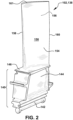
- FIGS. 2 and 3 show illustrative turbine components 102 of the type machined by machining system 104.
- FIG. 2 shows a perspective view of a turbine rotor blade 138.
- Turbine rotor blade 138 includes a root 140 by which rotor blade 138 attaches to a rotor of a turbine (not shown).
- Root 140 may include a dovetail 142 configured for mounting in a corresponding dovetail slot in the perimeter of a rotor wheel of a rotor.
- Root 140 may further include a shank 144 that extends between dovetail 142 and a blade platform 146, which is disposed at the junction of airfoil 150 and root 140 and defines a portion of the inboard boundary of the flow path through a turbine assembly of a turbine.
- Airfoil 150 of rotor blade 138 includes a concave pressure side (PS) outer wall 154 and a circumferentially or laterally opposite convex suction side (SS) outer wall 156 extending axially between opposite leading and trailing edges 158, 160 respectively. Walls 154 and 156 also extend in the radial direction from platform 146 to an outboard tip 161.
- an optional tip shroud (not shown) may be coupled at outboard tip 161.
- FIG. 3 shows a perspective view of a stationary turbine vane or nozzle 162 (hereafter "nozzle 162" for brevity).
- Nozzle 162 includes an outer platform 164 by which nozzle 162 attaches to a stationary casing (not shown) of a turbine.
- Outer platform 164 may include any now known or later developed mounting configuration for mounting in a corresponding mount in the casing.
- Nozzle 162 may further include an inner platform 166 for positioning between adjacent turbine rotor blades 138 ( FIG. 2 ), i.e., their platforms 146 ( FIG. 2 ), in a turbine.
- Airfoil 168 of nozzle 162 includes a concave pressure side (PS) outer wall 170 and a circumferentially or laterally opposite convex suction side (SS) outer wall 172 extending axially between opposite leading and trailing edges 174, 176, respectively. Walls 170 and 172 also extend in the radial direction from platform 166 to platform 164. Embodiments of the disclosure described herein may be applied to either turbine rotor blade 138, nozzle 162 or another turbine component. For purposes of description, only a turbine blade 138 is illustrated in subsequent drawings. It is understood that other features of turbine components 102 are not shown, such as but not limited to internal cooling structures, cutout shapes, outer wall angling/shapes, etc.
- turbine component 102 has a complex shape that may include many turns and shapes that are difficult to manually grasp.
- turbine component 102 may have sufficiently high weight that users of machining system 104 want to avoid bending and/or extending their arms to place turbine component 102 onto component fixture 110.
- handling system 100 includes a gripper 130 and may include a loading system 132.
- Gripper 130 functions to move component 102 from loading system 132 to and from component fixture 110 of machining system 104 in a safe and automated fashion.
- Gripper 130 includes a mounting arm 180 configured to be operatively coupled to tool handler 120 of machining system 104.
- Mounting arm 180 may include any structural element configured to function as a base of gripper 130 upon which other parts of gripper 130 are coupled.
- Mounting arm 180 may have any configuration necessary to position the other parts of gripper 130.
- Mounting arm 180 can be selectively coupled and moved to tool handler 120 in any now known or later developed fashion.
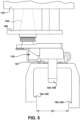
- a tool handler 120 of a particular machining system 104 includes a standard coupler 182 for all tools 122 ( FIG. 1 ) used therein.
- coupler 182 includes a spindle 183 that can be coupled to any tool 122 used in machining system 104.
- spindle 183 may have a frustoconical surface configured to mate in a similarly shaped opening in tool handler 120.
- the frustoconical (or tapered) spindle 183 is standard for, among others, many HAAS Automation models (e.g., CAT30, CAT40, CAT50).
- Tool handler 120 can selectively grasp an end of spindle 183 so tool handler can move tool 122, or gripper 130, and can rotate spindle 183 to rotate the position of tool 122 or gripper 130.
- tool handler 120 can handle gripper 130 just as any other tool 122 of machining system 104. More particularly, as understood in the art, tool handler 120 can select tools 122 from tool carrier 124 through an opening (not shown) in a ceiling of machine enclosure 112.
- Tool carrier 124 may move in any fashion under control of computer 106 to position the desired tool 122 or gripper 130 for selection by tool handler 120, e.g., tool carrier 124 may include a rotatable carriage having various location for storing tools 122 and gripper 130. Using coupler 182, gripper 130 can be stored, selected, handled and/or operated by tool carrier 124 and tool handler 120 just as any other tool 122 of machining system 104.
- Tool handler 120 and, in particular, coupler 182 may also include any now known or later developed mechanism(s) to provide power to tools 122 or gripper 130.
- coupler 182 includes a passage 185 therethrough for delivery of an operative fluid to operate an actuator 187 of gripper 130, as will be described herein.
- coupler 182 can take a variety of alternative forms depending on machining system 104, tool handler 120 and/or tool carrier 124 used. Other forms of coupler 182 are considered within the scope of the disclosure.
- Gripper 130 may also include a plurality of contact members 184 configured to selectively and collectively grasp turbine component 102.
- Contact members 184 may include any number of members for securely grasping part of turbine component 102. The number of contact members 184 required may differ based on turbine component 102 shape, size, weight, etc.
- contact members 184 are configured to grasp an airfoil 150, 168 of turbine component 102; however, other parts of turbine component 102 can also be grasped by gripper 130.
- contact members 184 may include a first fixed contact member 186 and a second fixed contact member 188. As shown in FIGS.
- first and second fixed contact members 186, 188 are distanced apart, i.e., distance D1, to allow passage of part (e.g., airfoil 150, 168) of turbine component 102 therebetween at a first longitudinal position L1 of the part and prevent passage of the part of turbine component 102 therebetween at a second longitudinal position L2 of the part.
- Fixed contact members 186, 188 may also have different lengths (see e.g., FIG. 8 ) to accommodate, for example, the curvature of airfoil 150, 168 of turbine component 102.
- contact members 184 may also include a moveable contact member 190 that grasps turbine component 102 against fixed contact members 186, 188.
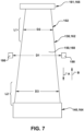
- FIG. 7 shows a schematic rendering of a turbine blade or nozzle 138, 162 showing an airfoil 150, 168 thereof having different cross-sectional widths D2, D3 at different longitudinal positions L1, L2 thereof.
- airfoil 150, 168 may have a first width D2 that is smaller than a second width D3 at a second longitudinal position L2.
- Longitudinal position L1 is different than longitudinal position L1, i.e., it is at a different longitudinal location along airfoil 150, 168.
- Longitudinal positions L1, L2 are shown with brackets to illustrate that they may not be just a single location but a range of locations along a longitudinal extent of airfoil 150, 168. The possible ranges of longitudinal positions do not overlap.
- distance D1 (of fixed contact members 186, 188 shown schematically in FIG. 7 ) is larger than width D2 but smaller than width D3 of airfoil 150, 168 of turbine component 102.
- fixed contact members 186, 188 of gripper 130 can be moved vertically to surround opposing surfaces of airfoil 150, 168 at first longitudinal position L1, i.e., for a release position of gripper 130.
- Gripper 130 can then be moved longitudinally relative to turbine component 102 and airfoil 150, 168 thereof such that fixed contact members 186, 188 of gripper 130 surround opposing surfaces of airfoil 150, 168 at second longitudinal position L2, i.e., for a grasp position of gripper 130 ( FIGS. 15-18 ). More particularly, per arrow A in FIG. 7 , gripper 130 may be moved longitudinally from first longitudinal position L1 to second longitudinal position L2. Since distance D1 between fixed contact members 186, 188 is smaller than width D3 of airfoil 150, 168 at second longitudinal position L2, turbine component 102 cannot move outside of fixed contact members 186, 188. In a similar fashion, per arrow B in FIG.
- gripper 130 may be moved longitudinally from second longitudinal position L2 to first longitudinal position L1, i.e., for a release position of gripper 130 ( FIGS. 14-19 ). Since distance D1 between fixed contact members 186, 188 is larger than width D2 of airfoil 150, 168 at first longitudinal position L1, fixed contact members 186, 188 can move past and from turbine component 102 after movement from second longitudinal position L2 to first longitudinal position L1. As will be further described, at least one of tool handler 120 and turbine component 102 (via component fixture 110 ( FIG. 1 ) can move linearly to move gripper 130 relative to turbine component 102 between first longitudinal position L1 and second longitudinal position L2. As will be described, the grasp position can be used for moving turbine component 102 from loading platform 210 to component fixture 110 prior to machining, or from component fixture 110 to loading platform 210 after machining.
- Gripper 130 also includes actuator 187 configured to operate gripper 130. More particularly, as noted, contact members 184 may include moveable contact member 190, which is operatively coupled to actuator 187. Moveable contact member 190 is selectively movable to cause grasping of turbine component 102 by plurality of contact members 184 in a selected longitudinal position of turbine component 102, i.e., second longitudinal position L2. More particularly, actuator 187 selectively moves at least one of contact members 184, i.e., moveable contact member 190, between a release position ( FIGS.
- contact members 184 receive or release a part, e.g., airfoil 150, 168, of turbine component 102 therebetween at first longitudinal position L1 of the part of turbine component 102 and a grasp position in which contact members 184 grasp the part of turbine component 102 at a second longitudinal position L2 of the part different than first longitudinal position L1.
- moveable contact member 190 moves linearly to force airfoil 150, 168 at or near second longitudinal position L2 against fixed contact members 186, 188 to grasp the turbine component. More particularly, moveable contact member 190 contacts turbine component 102 at or near second longitudinal position L2 and pushes fixed contact members 186, 188 against opposing surfaces of turbine component 102, thus securely grasping turbine component 102.
- second longitudinal position L2 may include a center of gravity of turbine component 102 to assist in balanced carrying of turbine component 102.
- Actuator 187 can include any now known or later developed actuator configured to move moveable contact member 190 to grasp turbine component 102 with fixed contact members 186, 188.
- actuator 187 includes a pneumatic actuator that receives a controlled air flow under control of computer 106 ( FIG. 1 ) through passage 185 ( FIG. 4 ) in coupler 182 ( FIG. 4).
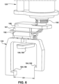
- FIGS. 4 and 6 show a conduit 192 for delivery of air from coupler 182 to actuator 187.
- Other delivery mechanisms may also be possible such as but not limited to fluid passages (not shown) in mounting arm 180 to deliver air from coupler 182 to actuator 187.
- Gripper 130 can include parts thereof sized to handle different sized and/or shaped turbine components 102.
- fixed contact members 186, 188 may be formed in an integral manner, e.g., as a C-shaped member 196 with a base 198.
- fixed contact members 186, 188 may have different lengths to accommodate, for example, the curvature of airfoil 150, 168 of turbine component 102.
- fixed contact member 186 may have a length D4 and fixed contact member 188 may have a length D5 that are different.
- Different contact member 184 arrangements can be created to handle different sized and/or shaped turbine components 102.
- a set of C-shaped members 196 with contact members with different spacing D1 and lengths D4, D5 can be created for different turbine components 102 or different sized turbine components 102, e.g., different sized first stage turbine blades of differently sized turbines.
- the different C-shaped members 196 can be mounted to a mounting arm 180 and actuator 187 arrangement that is universal to the different C-shaped members 196, e.g., through fastener(s) in opening(s) 200 in C-shaped members 196.
- Other manners of arranging length and spacing of contact members 184 other than C-shaped member 196 may also be possible.
- Different lengths of moveable contact member 190 can also be created for different sized turbine components 102 or, where possible, a single universally sized moveable contact member 190 can be used.
- Contact members 184 can also have surfaces thereof sized and/or shaped in any fashion to provide secure engagement thereof with whatever surface of turbine component 102 they contact.
- Contact members 184 can be, for example, partly or entirely curved or planar, have rough or smoothed surfaces and/or have different cross-sectional shapes.
- Contact members 184 can also have material selected to accommodate the material of turbine component 102, e.g., to ensure secure grasping without damage to turbine component 102.
- certain embodiments include gripper 130 for handling system 100 for turbine component 102 including airfoil 150, 168 ( FIGS. 2 , 3 and 7 ).
- Gripper 130 includes mounting arm 180 configured to be operatively coupled to tool handler 120 of computerized machining system 104.
- Gripper 130 also includes first contact member 186 fixed relative to mounting arm 180 and second contact member 188 fixed relative to mounting arm 180. As shown in FIG. 7 , first and second fixed contact members 186, 188 are distanced apart (distance D1) to allow passage of airfoil 150, 168 ( FIGS.
- Gripper 130 also includes third, moveable contact member 190 movable between a grasp position ( FIGS. 15-17 ) contacting a portion of turbine component 102 and seating turbine component 102 against first and second contact members 186, 188 and a release position ( FIGS. 14 and 19 ) out of contact with turbine component 102 and allowing movement of turbine component 102 relative to first and second contact members 186, 188.
- Gripper 130 also includes actuator 187 moving third contact member 190 between the grasp position and the release position, e.g., using controlled fluid flow to extend or retract moveable contact member 190 under control of computer 106.
- Handling system 100 may also include a loading system 132.
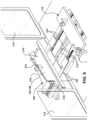
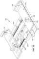
- Loading system 132 is shown, for example, in FIGS. 1 and 9-12 .
- Loading system 132 includes a loading platform 210.
- Loading platform 210 may include any structure for having turbine component 102 rested thereon in a predefined location.
- loading platform 210 may include a plate 216 having one or more component holders 218 thereon sized and/or shaped to hold turbine component 102 in a predefined location, e.g., for grasping by gripper 130.
- loading system 132 may include only a loading platform 210 in a loading position, as shown in FIG. 11 .
- turbine component 102 is free to be manually moved by a user, i.e., a human user (not shown), with less bending or extending their arms necessary to position turbine component 102 on component fixture 110.
- loading system 132 may include a (moveable) loading platform 210 and an actuator 212 configured to move loading platform 210 between a user-access position ( FIGS. 1 , 9 , 10 , 12 ) distal from component fixture 110 of machining system 104 and a loading position (e.g., FIG.
- loading system 132 may also include one or more linear guide tracks 214 mounting loading platform 210 for lateral movement relative to component fixture 110.
- FIG. 9 shows a perspective view of loading system 132 in a user-access position (also shown in FIG. 1 ) from within machine enclosure 112
- FIG. 10 shows a perspective view of loading system 132 from above in the user-access position from outside of machine enclosure 112
- FIG. 11 shows a perspective view of loading system 132 in a loading position from within machine enclosure 112
- FIG. 12 shows a perspective view of loading system 132 from underneath in the user-access position from outside of machine enclosure 112.
- Actuator 212 may include any now known or later developed form of linear actuator configured to move loading platform 210 between the user-access position ( FIGS. 1 , 9 , 10 , 12 ) and loading position ( FIG. 11 ) along one or more linear guide tracks 214.
- actuator 212 may include a pneumatic, hydraulic, or electric linear actuator operable manually or under control of computer 106.
- Actuator 212 and tracks 214 may be coupled to component fixture 110 for lateral movement therewith.
- distal from component fixture 110 indicates loading platform 210 is farther away than when proximate to component fixture 110.
- loading platform 210 is at least partially outside machine enclosure 112 of machining system 104 and is more readily user accessible than in the loading position.
- actuator 212 In the user-access position, actuator 212 has extended to move loading platform 210 away from component fixture 110 of machining system 104.
- Doors 114 of machine enclosure 112, where provided, are open in this setting.
- turbine component 102 With loading platform 210 in the user-access position, turbine component 102 is free to be manually moved by a user, i.e., a human user (not shown). That is, a user can easily and safely without bending or extending their arms, manually place or remove turbine component 102 to/from loading platform 210.
- loading platform 210 In contrast, in the loading position ( FIG. 11 ), loading platform 210 is inside machine enclosure 112 of machining system 104. In the loading position, actuator 212 has retracted to move loading platform 210 adjacent to (proximate to) component fixture 110 of machining system 104. Doors 114 of machine enclosure 112, where provided, can be closed in this setting.
- the user-access position and loading position can be controlled by, among other things, controlling actuator 212 extension/retraction between its limits, by the extend and retract limits of actuator 212 and/or by set detents on actuator 212 and/or tracks 214, where the latter is provided.
- loading system 132 may include alternative structure(s) for moving loading platform 210 between the user-access position and the loading position than a linear actuator and tracks, such as but not limited to structure and actuators arranged in a pivoting arrangement or a parallelogram arrangement.
- gripper 130 and tool handler 120 can, without user intervention, place or remove turbine component 102 to/from component fixture 110. More particularly, as will be described further herein, with loading platform 210 in the loading position ( FIG. 11 ), tool handler 120 moves gripper 130 between a first handler position over loading platform 210 in which gripper 130 moves between the release position and the grasp position to grasp or ungrasp turbine component 102 for movement of turbine component 102 toward or away from loading platform 210, and a second handler position over component fixture 110 in which gripper 130 moves between the release position and the grasp position to grasp or ungrasp turbine component 102 for movement of turbine component 102 to or from component fixture 110.
- handling system 100 all movement of handling system 100 is controlled by computer 106. More particularly, loading platform 210 moves between the user-access position and the loading position and gripper 130 moves between the first handler position, the second handler position, the release position, and the grasp position in an automated manner as part of a set of component machining instructions for machining system 104. The actual machining by machining system 104 occurs between activity by handling system 100.
- FIGS. 13-22 show additional perspective views of handling system 100 in operation from within machine enclosure 112.
- Handling system 100 may operate as part of an automated method of handling turbine component 102 relative to machining system 104, which may be precede and follow any now known or later developed automated method of machining turbine component 102 with machining system 104.
- loading platform 210 is positioned in the user-access position distal from component fixture 110 of machining system 104, whereby a user manually loads turbine component 102 ( FIG. 9 only) to loading platform 210.
- Doors 114 of machine enclosure 112, if provided, are open to allow loading platform 210 to extend to the user-access position.
- loading platform 210 is at least partially outside machine enclosure 112 of computerized machining system 104, i.e., with doors 114 open.
- a user may manually place turbine component 102 on loading platform 210, where holders 218 may operate to positively locate turbine component 102 in a predefined location, e.g., relative to the rest of loading platform 210, for easy locating by gripper 130 in subsequent steps.
- FIG. 11 shows positioning loading platform 210 with turbine component 102 in the loading position proximate component fixture 110.
- actuator 212 of loading system 132 retracts, forcing loading platform 210 to move towards component fixture 110.
- One or more guide tracks 214 may direct the linear movement of loading platform 210.
- loading system 132 may include alternative structure and actuators to provide the described movement of loading platform 210. As loading platform 210 moves to the loading position or thereafter, doors 114 of machine enclosure 112 close. Where actuator 212 is not provided, a user may manually place turbine component 102 on loading platform 210 in the loading position shown in FIG. 11 , where holders 218 may operate as previously described.
- FIGS. 13-19 show moving turbine component 102 to/from loading platform 210 and to/from component fixture 110 of computerized machining system 104 using gripper 130.
- gripper 130 has contact members 184 configured to collectively grasp turbine component 102 and is operatively coupled to tool handler 120 of computerized machining system 104.
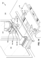
- FIGS. 13 and 14 show gripper 130 in the release position relative to turbine component 102, i.e., with gripper 130 not engaged to hold turbine component 102, which is resting on loading platform 210.
- gripper 130 has been selected by tool handler 120 from tool carrier 124 ( FIG.
- gripper 130 can grasp it without any further identification of location thereof.
- gripper 130 can include, for example, physical or optical probes to confirm positioning of turbine component 102 on loading platform 210.
- loading platform 210 is inside machine enclosure 112, if provided, of computerized machining system 104.
- FIG. 14 shows tool handler 120 lowering gripper 130 over first longitudinal position L1 of turbine component 102.
- distance D 1 FIG. 7
- gripper 130 could be passed longitudinally over, for example, outboard tip 161 ( FIG. 2 ) of airfoil 150 of a turbine blade 138 ( FIG. 2 ) with no tip shroud. In this manner, contact members 186, 188 can be positioned in first longitudinal position L1 without passing cross-sectionally over airfoil 150.
- tool handler 120 and/or component fixture 110 next linearly move gripper 130 relative to turbine component 102, such that gripper 130 moves between first longitudinal position L1 and second longitudinal position L2.
- component fixture 110 and, hence, turbine component 102 is moved away from the viewer on the page to move gripper 130 between first longitudinal position L1 and second longitudinal position L2.
- turbine component 102 on component fixture 110 is moved to place gripper 130 over second longitudinal position L2.
- tool handler 120 can also move gripper 130 during this process, if desired.
- Contact members 184 generally do not contact airfoil 150, 168 during this movement, other than perhaps some minor sliding contact near the end of the movement.
- FIGS. 15-18 show tool handler 120 moving gripper 130. As shown in FIGS. 15-18 , tool handler 120 moves gripper 130 between a first handler position over loading platform 210 and a second handler position over component fixture 110.
- FIGS. 15-16 show tool handler 120 and gripper 130 in the first handler position over loading platform 210 in which gripper 130 can move between the release position and the grasp position to grasp or ungrasp the turbine component 102 for movement of turbine component 102 to or from loading platform 210.
- FIGS. 17-18 show tool handler 120 and gripper 130 in the second handler position over component fixture 110 in which gripper 130 moves between the release position and the grasp position to grasp or ungrasp turbine component 102 for movement of turbine component 102 to or from component fixture 110.
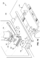
- FIG. 15 shows gripper 130 in the grasp position over loading platform 210 with actuator 187 actuated to extend moveable contact member 190 into contact with turbine component 102 at or near longitudinal position L2.
- actuator 187 actuated to extend moveable contact member 190 into contact with turbine component 102 at or near longitudinal position L2.
- turbine component 102 is firmly secured and movable by gripper 130.
- FIG. 16 shows lifting of turbine component 102 from loading platform 210 with gripper 130.
- tool handler 120 raises up (vertically on page) lifting gripper 130 and turbine component 102.
- FIG. 17 shows moving turbine component 102 over component fixture 110 of machining system 104.
- tool handler 120 and/or component fixture 110 move in a manner to place turbine component 102 over component fixture 110. That is, generally speaking, tool handler 120 moves to the right on the page and/or component fixtures 110 moves left on the page.
- One or both of tool handler 120 and component fixture 110 may also move into or out of the page to longitudinally align tool component 102 in a desired position over component fixture 110.
- FIG. 18 shows lowering of turbine component 102 onto component fixture 110.
- tool handler 120 lowers down (vertically on page) lowering gripper 130 and turbine component 102.
- actuator 187 of gripper 130 retracts moveable contact member 190 to a retracted position, placing gripper 130 into the release position over component fixture 110.
- tool handler 120 and/or component fixture 110 next linearly move turbine component 102 to move gripper 130 relative to turbine component 102 between second longitudinal position L2 and first longitudinal position L1.
- turbine component 102 on component fixture 110 is moved towards the viewer on the page to move gripper 130 between second longitudinal position L2 and first longitudinal position L1.
- tool handler 120 can also move gripper 130 during this process, if desired.
- Contact members 184 are released from contact with airfoil 150, 168 during this movement, other than perhaps some minor sliding contact near the start of the movement.
- Component fixture 110 may include any now known or later developed structures to grasp turbine component 102. As known in the art, component fixture 110 can also move turbine component 102 in any manner, e.g., horizontally, vertically and/or tilting, using any necessary actuators controlled by computer 106.
- FIG. 20-21 show various operations of machining system 104, with FIG. 21 showing machining turbine component 102 based on a set of component machining instructions.
- tool handler 120 has switched out gripper 130 for, for example, a conventional physical or optical probe 220, which can be used in an optional step to confirm positioning of turbine component 102 on component fixture 110.
- tool handler 120 has switched out probe 220 for a machining tool 222.
- the machining shown in FIG. 21 may include using any now known or later developed process of machining system 104 as directed by a set of component machining instructions.
- machining tool 222 includes a milling head, and coolant 224 is being delivered to tool 222.
- tool handler 120 and/or component fixture 110 would be moved to move tool 222 in contact with turbine component 102 to perform the machining.
- Tool 222 is shown above and out of contact with tool component for illustration purposes, it may not be visible during the machining.
- tool handler 120 can optionally select from a variety of post-machining processing tools from tool carrier 124 ( FIG. 1 ), for cleaning machining debris, removing contaminants and/or drying the component using air jets or high-speed fans.
- the process includes moving turbine component 102 from component fixture 110 of computerized machining system 104 to loading platform 210 using gripper 130 operatively coupled to tool handler 120 of computerized machining system 104. More particularly, as shown in FIG. 19 , tool handler 120 switches out machining tool 222 ( FIG. 20 ) and selects gripper 130. FIG. 19 shows lowering of gripper 130 over turbine component 102. Here, tool handler 120 lowers down (vertically on page) lowering gripper 130 over turbine component 102. In the position in FIG. 19 , actuator 187 of gripper 130 has moveable contact member 190 in a retracted position, i.e., with gripper 130 in the release position over component fixture 110.
- tool handler 120 and/or component fixture 110 next linearly move turbine component 102 to move gripper 130 relative to turbine component 102 between first longitudinal position L1 and second longitudinal position L2.
- component fixture 110 is moved away from the viewer on the page to move gripper 130 between first longitudinal position L1 and second longitudinal position L2.
- tool handler 120 can also move gripper 130 during this process, if desired.
- Contact members 184 are released from contact with airfoil 150, 168 during this movement, other than perhaps some minor sliding contact near the end of the movement.
- FIG. 18 also shows gripper 130 in the grasp position over component fixture 110 with actuator 187 actuated to extend moveable contact member 190 into contact with turbine component 102 at or near longitudinal position L2. In this setting, turbine component 102 is firmly secured and movable by gripper 130.
- FIG. 17 shows lifting of turbine component 102 from component fixture 110.
- tool handler 120 raises up (vertically on page) lifting gripper 130 and turbine component 102.
- FIG. 16 shows moving turbine component 102 from over component fixture 110 of machining system 104.
- tool handler 120 and/or component fixture 110 move in a manner to place turbine component 102 over loading platform 210. That is, generally speaking, tool handler 120 moves to the left on the page and/or component fixtures 110 moves right on the page.
- One or both of tool handler 120 and component fixture 110 may also move into or out of the page to longitudinally align tool component 102 in a desired position over loading platform 210, e.g., over component holders 218.
- FIG. 15 shows lowering of turbine component 102 onto loading platform 210.
- tool handler 120 lowers down (vertically on page) lowering gripper 130 and turbine component 102.
- actuator 187 of gripper 130 moves moveable contact member 190 to a retracted position, placing gripper 130 into the release position over loading platform 210.
- tool handler 120 and/or component fixture 110 next linearly move turbine component 102 to move gripper 130 relative to turbine component 102 between second longitudinal position L2 and first longitudinal position L1.
- component fixture 110 is moved towards the viewer on the page to move gripper 130 between second longitudinal position L2 and first longitudinal position L1.
- tool handler 120 can also move gripper 130 during this process, if desired.
- Contact members 184 are released from contact with airfoil 150, 168 during this movement, other than perhaps some minor sliding contact near the start of the movement.
- tool handler 120 can raise gripper 130 in the first longitudinal position L1, leaving turbine component 102 on loading platform 210.
- FIGS. 1 and 9 show positioning loading platform 210 in the user-access position distal from component fixture 110 of machining system 104.
- a user can manually unload turbine component 102 from loading platform 210. That is, with loading platform 210 again positioned in the user-access position distal from component fixture 110 of machining system 104, a user can manually unload turbine component 102 from loading platform 210.
- Doors 114 of machine enclosure 112, if provided, are open to allow loading platform 210 to extend to the user-access position.
- loading platform 210 is at least partially outside machine enclosure 112 of computerized machining system 104, i.e., with doors 114 open.
- a user may manually remove turbine component 102 from loading platform 210 in any known position. Where actuator 212 for loading system 132 is not provided, a user can manually remove turbine component from loading platform 210 in the loading position shown in FIG. 11 (with doors 114 open, if provided).
- Embodiments of the disclosure provide various technical and commercial advantages, examples of which are discussed herein.
- the handling system allows easier loading and unloading of heavy or complex shaped turbine components, like turbine blades or nozzles with airfoils, without extensive bending over and/or extending while holding the turbine component.
- the handling system is advantageous on machining systems with a machine enclosure, but can also be helpful on machining systems without a machine enclosure.
- Approximating language may be applied to modify any quantitative representation that could permissibly vary without resulting in a change in the basic function to which it is related. Accordingly, a value modified by a term or terms, such as “about,” “approximately” and “substantially,” are not to be limited to the precise value specified. In at least some instances, the approximating language may correspond to the precision of an instrument for measuring the value.
- range limitations may be combined and/or interchanged; such ranges are identified and include all the sub-ranges contained therein unless context or language indicates otherwise. "Approximately” or “about,” as applied to a particular value of a range, applies to both end values and, unless otherwise dependent on the precision of the instrument measuring the value, may indicate +/- 10% of the stated value(s).
Landscapes
- Engineering & Computer Science (AREA)
- Mechanical Engineering (AREA)
- Electrical Discharge Machining, Electrochemical Machining, And Combined Machining (AREA)
- Feeding Of Workpieces (AREA)
Abstract
A handling system (100) for a turbine component (102) and a computerized machining system (104) are provided. A gripper (130) of the system includes a mounting arm (180) operatively coupled to a tool handler (120) of the machining system, a plurality of contact members (184) configured to collectively grasp the turbine component (102), and a first actuator (187) configured to move at least one of the contact members (184) between a release position in which the contact members receive a part of the turbine component (102) therebetween at a first longitudinal position (L1) thereof and a grasp position in which the contact members (184) grasp the part at a second longitudinal position (L2) thereof different than the first longitudinal position. The tool handler (120) and/or the turbine component (102) is linearly moved to move the gripper (130) relative to the turbine component between the first longitudinal position (L1) and the second longitudinal position (L2). A loading system allowing easier loading/unloading of the turbine component may also be provided.
Description
- The disclosure relates generally to part handling and machining. More specifically, the disclosure relates to a handling system for a turbine component for a computerized machining system.
- Computer numerical control (CNC) machining systems automatically machine metal or other rigid material components using a computer. The CNC machining system processes the component to meet specifications by following a set of program instructions and without an operator manually controlling the machining operation. The machining system typically includes a component fixture that holds and moves the component as the machining occurs, e.g., in any direction in a horizontal, vertical and/or tilting manner. The component fixture is oftentimes positioned within a machine enclosure in which work on the component is performed. The machine enclosure may have automated doors that open and close before and after machining. A tool handler can select from a number of tools, e.g., on a tool carrier. The computer controls operation and positioning of the tools and the component relative to one another via the tool holder and/or the component fixture during automated machining of the component. The tools may take a variety of forms such as but not limited to: tools for physically changing the component such as milling, drilling, tapping, boring, abrading, etc.; tools for confirming position of the component and/or accuracy of the machining such as physical or optical probes; and tools for post-machining processing like cleaning machining debris, removing contaminants and/or drying the component such as air jets or high-speed fans. During operation, some machining requires a coolant for the machining tool and/or the component. In this case, the machining tool may include a coolant delivery system (e.g., a pump, conduit, and nozzle) to deliver a coolant to the machining tool and/or the component.
- Loading and unloading components that are heavy or have a complex shape to the component fixture can be a challenge. For example, where a machine enclosure is used, positioning the component on the component fixture may require a user to manually lift the component and reach to place the component on the component fixture by, for example, bending over and/or extending their arms into the machine enclosure while holding the component. One example component that may be heavy and/or have a complex shape includes a turbine component with an airfoil such as a turbine blade or nozzle.
- All aspects, examples and features mentioned below can be combined in any technically possible way.
- An aspect of the disclosure provides a handling system for a turbine component relative to a computerized machining system, the handling system comprising: a gripper including: a mounting arm configured to be operatively coupled to a tool handler of the computerized machining system; a plurality of contact members configured to collectively grasp the turbine component, and a first actuator configured to move at least one of the plurality of contact members between a release position in which the plurality of contact members receive a part of the turbine component therebetween at a first longitudinal position of the part of the turbine component and a grasp position in which the plurality of contact members grasp the part of the turbine component at a second longitudinal position of the part different than the first longitudinal position, wherein at least one of the tool handler and the turbine component is linearly moved to move the gripper relative to the turbine component between the first longitudinal position and the second longitudinal position.
- Another aspect of the disclosure includes any of the preceding aspects, and further comprising a loading system including a loading platform and a second actuator configured to move the loading platform between a user-access position distal from a component fixture of the computerized machining system and a loading position proximate the component fixture of the computerized machining system.
- Another aspect of the disclosure includes any of the preceding aspects, and further comprising one or more linear guide tracks mounting the loading platform for lateral movement relative to the component fixture, wherein the second actuator includes a linear actuator configured to move the loading platform between the user-access position and the loading position along the one or more linear guide tracks.
- Another aspect of the disclosure includes any of the preceding aspects, and, in the user-access position, the loading platform is at least partially outside a machine enclosure of the computerized machining system and, in the loading position, the loading platform is inside the machine enclosure of the computerized machining system.
- Another aspect of the disclosure includes any of the preceding aspects, and, with the loading platform in the loading position, the tool handler moves the gripper between: a first handler position over the loading platform in which the gripper moves between the release position and the grasp position to grasp or ungrasp the turbine component for movement of the turbine component to or from the loading platform; and a second handler position over the component fixture in which the gripper moves between the release position and the grasp position to grasp or ungrasp the turbine component for movement of the turbine component to or from the component fixture.
- Another aspect of the disclosure includes any of the preceding aspects, and the loading platform moves between the user-access position and the loading position and the gripper moves between the first handler position, the second handler position, the release position and the grasp position in an automated manner as part of a set of component machining instructions for the computerized machining system.
- Another aspect of the disclosure includes any of the preceding aspects, and, with the loading platform in the loading position, the tool handler moves the gripper between: a first handler position over the loading platform in which the gripper moves between the release position and the grasp position to grasp or ungrasp the turbine component for movement of the turbine component to or from the loading platform; and a second handler position over the component fixture in which the gripper moves between the release position and the grasp position to grasp or ungrasp the turbine component for movement of the turbine component to or from the component fixture.
- Another aspect of the disclosure includes any of the preceding aspects, and, with the loading platform in the user-access position, the turbine component is free to be manually moved by a user.
- Another aspect of the disclosure includes any of the preceding aspects, and the second longitudinal position of the turbine component includes a center of gravity of the turbine component.
- Another aspect of the disclosure includes any of the preceding aspects, and the first actuator includes a pneumatic actuator.
- Another aspect of the disclosure includes any of the preceding aspects, and the plurality of contact members includes: a first fixed contact member and a second fixed contact member, the first and second fixed contact members distanced apart to allow passage of the part of the turbine component therebetween at the first longitudinal position of the part and prevent passage of the part of the turbine component therebetween at the second longitudinal position; and a moveable contact member operatively coupled to the first actuator to selectively cause grasping of the turbine component by the plurality of contact members in the second longitudinal position.
- Another aspect of the disclosure includes any of the preceding aspects, and the turbine component includes a turbine blade or nozzle, and the part of the turbine component includes an airfoil.
- An aspect of the disclosure includes an automated method of handling a turbine component relative to a computerized machining system, the automated method comprising: positioning a loading platform in a user-access position distal from a component fixture of the computerized machining system, whereby a user manually loads the turbine component to the loading platform; positioning the loading platform with the turbine component in a loading position proximate the component fixture; moving the turbine component from the loading platform to a component fixture of the computerized machining system using a gripper having a plurality of contact members configured to collectively grasp the turbine component, the gripper operatively coupled to a tool handler of the computerized machining system; and machining the turbine component using the computerized machining system and a set of component machining instructions.
- Another aspect of the disclosure includes any of the preceding aspects, and further comprising, after the machining: moving the turbine component from the component fixture of the computerized machining system to the loading platform using the gripper operatively coupled to the tool handler of the computerized machining system; and positioning the loading platform in the user-access position distal from the component fixture of the computerized machining system, whereby a user manually unloads the turbine component from the loading platform.
- Another aspect of the disclosure includes any of the preceding aspects, and the gripper includes a first actuator configured to move at least one of the plurality of contact members between a release position in which the plurality of contact members receive a part of the turbine component therebetween at a first longitudinal position of the part of the turbine component and a grasp position in which the plurality of contact members grasp the part of the turbine component at a second longitudinal position of the part different than the first longitudinal position, and further comprising linearly moving at least one of the tool handler and the turbine component to move the gripper relative to the turbine component between the first longitudinal position and the second longitudinal position.
- Another aspect of the disclosure includes any of the preceding aspects, and the second longitudinal position of the turbine component includes a center of gravity of the turbine component.
- Another aspect of the disclosure includes any of the preceding aspects, and further comprising one or more linear guide tracks for mounting the loading platform for lateral movement relative to the component fixture, and further comprising a second actuator configured to move the loading platform between the user-access position and the loading position along the one or more linear guide tracks.
- Another aspect of the disclosure includes any of the preceding aspects, and, in the user-access position, the loading platform is at least partially outside a machine enclosure of the computerized machining system and, in the loading position, the loading platform is inside the machine enclosure of the computerized machining system.
- Another aspect of the disclosure includes any of the preceding aspects, and, with the loading platform in the loading position, the tool handler moves the gripper between: a first handler position over the loading platform in which the gripper moves between the release position and the grasp position to grasp or ungrasp the turbine component for movement of the turbine component to or from the loading platform; and a second handler position over the component fixture in which the gripper moves between the release position and the grasp position to grasp or ungrasp the turbine component for movement of the turbine component to or from the component fixture.
- An aspect of the disclosure includes a gripper for a handling system for a turbine component including an airfoil, the gripper comprising: a mounting arm configured to be operatively coupled to a tool handler of a computerized machining system; a first contact member fixed relative to the mounting arm; a second contact member fixed relative to the mounting arm, the first and second contact members distanced apart to allow passage of the airfoil therebetween at a first longitudinal position of the airfoil having a first width and prevent passage of the airfoil therebetween at a second longitudinal position of the airfoil having a second, wider width than the first width; a third contact member moveable between a grasp position contacting a portion of the turbine component and seating the turbine component against the first and second contact members and a release position out of contact with the turbine component and allowing movement of the turbine component relative to the first and second contact members; and an actuator moving the third contact member between the grasp position and the release position.
- Two or more aspects described in this disclosure, including those described in this summary section, may be combined to form implementations not specifically described herein. That is, all embodiments described herein can be combined with each other.
- The details of one or more implementations are set forth in the accompanying drawings and the description below. Other features, objects and advantages will be apparent from the description and drawings, and from the claims.
- These and other features of this disclosure will be more readily understood from the following detailed description of the various aspects of the disclosure taken in conjunction with the accompanying drawings that depict various embodiments of the disclosure, in which:
-
FIG. 1 shows a perspective view of a handling system on a computer numerical control machining system, according to embodiments of the disclosure; -
FIG. 2 shows a perspective view of an illustrative turbine component in the form of a turbine blade that can be handled by a handling system, according to embodiments of the disclosure; -
FIG. 3 shows a perspective view of an illustrative turbine component in the form of a turbine nozzle that can be handled by a handling system, according to embodiments of the disclosure; -
FIG. 4 shows a side view of a gripper of a handling system apart from a tool handler of the machining system, according to embodiments of the disclosure; -
FIG. 5 shows a side view of a gripper of a handling system on a tooler handler of the machining system, according to embodiments of the disclosure; -
FIG. 6 shows a perspective view of a gripper of a handling system on a tooler handler of the machining system, according to embodiments of the disclosure; -
FIG. 7 shows a schematic view of a turbine component, according to embodiments of the disclosure; -
FIG. 8 shows a side view of fixed contact members of a gripper of a handling system, according to embodiments of the disclosure; -
FIG. 9 shows a perspective view of a handling system (from within a machine enclosure of the machining system) in a user-access position of a loading platform, according to embodiments of the disclosure; -
FIG. 10 shows a downward perspective view of the loading platform of the handling system in the user-access position, according to embodiments of the disclosure; -
FIG. 11 shows a perspective view of a handling system (from within a machine enclosure of the machining system) in a loading position of a loading platform, according to embodiments of the disclosure; -
FIG. 12 shows an upward perspective view of the loading platform of the handling system in the user-access position of the loading platform, according to embodiments of the disclosure; -
FIG. 13 shows a perspective view of a gripper of the handling system (from within a machine enclosure of the machining system) in the loading position of the loading platform, according to embodiments of the disclosure; -
FIG. 14 shows a perspective view of the gripper (from within a machine enclosure of the machining system) in a released position over a first longitudinal position of a turbine component in the loading position of the loading platform, according to embodiments of the disclosure; -
FIG. 15 shows a perspective view of the gripper (from within a machine enclosure of the machining system) in a grasp position over a second longitudinal position of the turbine component and over the loading platform, according to embodiments of the disclosure; -
FIG. 16 shows a perspective view of the gripper (from within a machine enclosure of the machining system) moving the turbine component to or from the loading position of the loading platform, according to embodiments of the disclosure; -
FIG. 17 shows a perspective view of the gripper (from within a machine enclosure of the machining system) moving the turbine component to or from the component fixture of the machining system, according to embodiments of the disclosure; -
FIG. 18 shows a perspective view of the gripper (from within a machine enclosure of the machining system) in a grasp position over a second longitudinal position of the turbine component and over the component fixture of the machining system, according to embodiments of the disclosure; -
FIG. 19 shows a perspective view of the gripper (from within a machine enclosure of the machining system) in a release position over a first longitudinal position of the turbine component and over the component fixture of the machining system, according to embodiments of the disclosure; -
FIG. 20 shows a perspective view of a physical or optical probe (from within a machine enclosure of the machining system) confirming a position of the turbine component on the component fixture, according to embodiments of the disclosure; and -
FIG. 21 shows a perspective view of a machining tool (from within a machine enclosure of the machining system) machining the turbine component on the component fixture, according to embodiments of the disclosure. - It is noted that the drawings of the disclosure are not necessarily to scale. The drawings are intended to depict only typical aspects of the disclosure and therefore should not be considered as limiting the scope of the disclosure. In the drawings, like numbering represents like members between the drawings.
- As an initial matter, in order to clearly describe the current disclosure, it will become necessary to select certain terminology when referring to and describing relevant machine components within the illustrative application of a computerized machining system. When doing this, if possible, common industry terminology will be used and employed in a manner consistent with its accepted meaning. Unless otherwise stated, such terminology should be given a broad interpretation consistent with the context of the present application and the scope of the appended claims. Those of ordinary skill in the art will appreciate that often a particular component may be referred to using several different or overlapping terms. What may be described herein as being a single part may include and be referenced in another context as consisting of multiple components. Alternatively, what may be described herein as including multiple components may be referred to elsewhere as a single part.
- In addition, several descriptive terms may be used regularly herein, and it should prove helpful to define these terms at the onset of this section. "Distal" and "proximate" relative to a stated element are relative terms in that "distal" refers to a location distanced from the stated element compared to the proximate location, and "proximate" refers to a location closer to the stated element than the distal location. In addition, several descriptive terms may be used regularly herein, as described below. The terms "first," "second," and "third," may be used interchangeably to distinguish one component from another and are not intended to signify location or importance of the individual components.
- The terminology used herein is for the purpose of describing particular embodiments only and is not intended to be limiting of the disclosure. As used herein, the singular forms "a," "an," and "the" are intended to include the plural forms as well, unless the context clearly indicates otherwise. It will be further understood that the terms "comprises" and/or "comprising," when used in this specification, specify the presence of stated features, integers, steps, operations, members, and/or components, but do not preclude the presence or addition of one or more other features, integers, steps, operations, members, components, and/or groups thereof. "Optional" or "optionally" means that the subsequently described event may or may not occur or that the subsequently described feature may or may not be present and that the description includes instances where the event occurs or the feature is present and instances where the event does not occur or the feature is not present.
- Where a member or layer is referred to as being "on," "engaged to," "connected to," "coupled to," or "mounted to" another member or layer, it may be directly on, engaged, connected, coupled, or mounted to the other member or layer, or intervening members or layers may be present. In contrast, when a member is referred to as being "directly on," "directly engaged to," "directly connected to," or "directly coupled to" another member or layer, there are no intervening members or layers present. Other words used to describe the relationship between members should be interpreted in a like fashion (e.g., "between" versus "directly between," "adjacent" versus "directly adjacent," etc.). As used herein, the term "and/or" includes any and all combinations of one or more of the associated listed items. The verb forms of "couple" and "mount" may be used interchangeably herein.
- As indicated above, the disclosure provides a handling system for a turbine component relative to a computer numerical control (CNC) machining system. A gripper of the handling system includes a mounting arm configured to be operatively coupled to a tool handler of the machining system, a plurality of contact members configured to collectively grasp the turbine component, and a first actuator configured to move at least one of the contact members between a release position in which the contact members receive a part of the turbine component therebetween at a first longitudinal position thereof and a grasp position in which the contact members grasp the part at a second longitudinal position thereof different than the first longitudinal position. The tool handler and/or the turbine component travels linearly to move the gripper relative to the turbine component between the first longitudinal position and the second longitudinal position. The handling system may also include a loading system allowing easier loading/unloading of the turbine component. The handling system allows easier loading and unloading of heavy or complex shaped turbine components, like turbine blades or nozzles with airfoils, without extensive bending over and/or extending while holding the turbine component. The handling system is advantageous on machining systems with a machine enclosure but can also be helpful on machining systems without a machine enclosure.
-
FIG. 1 shows a perspective view of ahandling system 100 for aturbine component 102 relative to a computer numericalcontrol machining system 104. As will be described herein, handlingsystem 100 may include agripper 130 and aloading system 132. Computer numericalcontrol machining system 104 may include any now known or later developed computer numerical control-based machining system 104 (hereafter "machining system" or "computerized machining system" for brevity). In one non-limiting example,machining system 104 may include but is not limited to a HAAS model that includes a vertical spindle coupler such as the VF series, Universal Machine series, VR series, and TR series, available from HAAS Automation Inc., Oxnard, CA.Machining system 104 automatically handles or machines metal or other rigid material components using acomputer 106.Machining system 104 processesturbine component 102 to meet specifications by following a set of program instructions and without an operator manually controlling the machining operation.Machining system 104 includes acomponent fixture 110 that holds and movesturbine component 102 as the machining occurs. In certain embodiments, although not necessary in all cases,component fixture 110 may be positioned within amachine enclosure 112 in whichturbine component 102 is machined.Machine enclosure 112 may include any now known or later developed enclosure to protect users from the machining, e.g., airborne debris, broken parts, etc.Machine enclosure 112 may include a set ofdoors 114 that can open and close to allow or deny access tocomponent fixture 110. Note,doors 114 are shown retracted to an open position inFIG. 1 . In many cases,doors 114 are automated to open and close under control ofcomputer 106. -
Machining system 104 also includes atool handler 120 that can select from a number oftools 122, e.g., on atool carrier 124, for operating on or relative toturbine component 102. For example,tool handler 120 may select a tool fromtool carrier 124 through an opening in a ceiling ofmachine enclosure 112.Tool carrier 124 may move, e.g., rotate, under control ofcomputer 106 to place a desiredtool 122 within the grasp oftool handler 120.Computer 106 controls the operation and positioning oftools 122 andturbine component 102 viacomponent fixture 110 and/ortool handler 120 during automated machining ofturbine component 102.Tools 122 may take any now known or later developed form, such as but not limited to: tools for physically changing the component such as milling, drilling, tapping, boring, abrading, etc.; tools for confirming position of the component and/or accuracy of the machining such as physical or optical probes; and tools for post-machining processing like cleaning machining debris, removing contaminants and/or drying the component such as air jets or high-speed fans.Machining system 104 may also include any now known or later developed coolant delivery system (not shown inFIG. 1 ) where machining requires coolingmachining tool 122 and/orturbine component 102. As the details ofmachining system 104 are otherwise well known in the art, no further description is necessary. - For purposes of description,
turbine component 102 is illustrated as a turbine blade or nozzle.FIGS. 2 and3 showillustrative turbine components 102 of the type machined by machiningsystem 104.FIG. 2 shows a perspective view of a turbine rotor blade 138. Turbine rotor blade 138 includes aroot 140 by which rotor blade 138 attaches to a rotor of a turbine (not shown).Root 140 may include adovetail 142 configured for mounting in a corresponding dovetail slot in the perimeter of a rotor wheel of a rotor.Root 140 may further include ashank 144 that extends betweendovetail 142 and ablade platform 146, which is disposed at the junction ofairfoil 150 androot 140 and defines a portion of the inboard boundary of the flow path through a turbine assembly of a turbine.Airfoil 150 of rotor blade 138 includes a concave pressure side (PS)outer wall 154 and a circumferentially or laterally opposite convex suction side (SS)outer wall 156 extending axially between opposite leading and trailingedges Walls platform 146 to anoutboard tip 161. As known in the art, an optional tip shroud (not shown) may be coupled atoutboard tip 161. -
FIG. 3 shows a perspective view of a stationary turbine vane or nozzle 162 (hereafter "nozzle 162" for brevity). Nozzle 162 includes anouter platform 164 by which nozzle 162 attaches to a stationary casing (not shown) of a turbine.Outer platform 164 may include any now known or later developed mounting configuration for mounting in a corresponding mount in the casing. Nozzle 162 may further include aninner platform 166 for positioning between adjacent turbine rotor blades 138 (FIG. 2 ), i.e., their platforms 146 (FIG. 2 ), in a turbine.Airfoil 168 of nozzle 162 includes a concave pressure side (PS)outer wall 170 and a circumferentially or laterally opposite convex suction side (SS)outer wall 172 extending axially between opposite leading and trailingedges Walls platform 166 toplatform 164. Embodiments of the disclosure described herein may be applied to either turbine rotor blade 138, nozzle 162 or another turbine component. For purposes of description, only a turbine blade 138 is illustrated in subsequent drawings. It is understood that other features ofturbine components 102 are not shown, such as but not limited to internal cooling structures, cutout shapes, outer wall angling/shapes, etc. In any event, it will be understood thatturbine component 102 has a complex shape that may include many turns and shapes that are difficult to manually grasp. In addition,turbine component 102 may have sufficiently high weight that users ofmachining system 104 want to avoid bending and/or extending their arms to placeturbine component 102 ontocomponent fixture 110. - With reference to
FIG. 1 andFIGS. 4-6 , handlingsystem 100 includes agripper 130 and may include aloading system 132.Gripper 130 functions to movecomponent 102 fromloading system 132 to and fromcomponent fixture 110 ofmachining system 104 in a safe and automated fashion.Gripper 130 includes a mountingarm 180 configured to be operatively coupled totool handler 120 ofmachining system 104. Mountingarm 180 may include any structural element configured to function as a base ofgripper 130 upon which other parts ofgripper 130 are coupled. Mountingarm 180 may have any configuration necessary to position the other parts ofgripper 130. Mountingarm 180 can be selectively coupled and moved totool handler 120 in any now known or later developed fashion. In most cases, atool handler 120 of aparticular machining system 104 includes astandard coupler 182 for all tools 122 (FIG. 1 ) used therein. For theillustrative machining system 104 described herein,coupler 182 includes aspindle 183 that can be coupled to anytool 122 used inmachining system 104. In the example shown,spindle 183 may have a frustoconical surface configured to mate in a similarly shaped opening intool handler 120. The frustoconical (or tapered)spindle 183 is standard for, among others, many HAAS Automation models (e.g., CAT30, CAT40, CAT50). Other similar spindle versions are also possible, such as those for machining systems available from HSK Machineworks.Tool handler 120 can selectively grasp an end ofspindle 183 so tool handler can movetool 122, orgripper 130, and can rotatespindle 183 to rotate the position oftool 122 orgripper 130. Hence, withcoupler 182 on mountingarm 180 ofgripper 130,tool handler 120 can handlegripper 130 just as anyother tool 122 ofmachining system 104. More particularly, as understood in the art,tool handler 120 can selecttools 122 fromtool carrier 124 through an opening (not shown) in a ceiling ofmachine enclosure 112.Tool carrier 124 may move in any fashion under control ofcomputer 106 to position the desiredtool 122 orgripper 130 for selection bytool handler 120, e.g.,tool carrier 124 may include a rotatable carriage having various location for storingtools 122 andgripper 130. Usingcoupler 182,gripper 130 can be stored, selected, handled and/or operated bytool carrier 124 andtool handler 120 just as anyother tool 122 ofmachining system 104. -
Tool handler 120 and, in particular, coupler 182 (frustoconical spindle 183 thereof) may also include any now known or later developed mechanism(s) to provide power totools 122 orgripper 130. With regards togripper 130,coupler 182 includes apassage 185 therethrough for delivery of an operative fluid to operate anactuator 187 ofgripper 130, as will be described herein. - It is emphasized that
coupler 182 can take a variety of alternative forms depending onmachining system 104,tool handler 120 and/ortool carrier 124 used. Other forms ofcoupler 182 are considered within the scope of the disclosure. -
Gripper 130 may also include a plurality ofcontact members 184 configured to selectively and collectively graspturbine component 102.Contact members 184 may include any number of members for securely grasping part ofturbine component 102. The number ofcontact members 184 required may differ based onturbine component 102 shape, size, weight, etc. In the example shown herein,contact members 184 are configured to grasp anairfoil turbine component 102; however, other parts ofturbine component 102 can also be grasped bygripper 130. With regard to grasping anairfoil contact members 184 may include a first fixedcontact member 186 and a second fixedcontact member 188. As shown inFIGS. 4-6 , first and secondfixed contact members airfoil 150, 168) ofturbine component 102 therebetween at a first longitudinal position L1 of the part and prevent passage of the part ofturbine component 102 therebetween at a second longitudinal position L2 of the part.Fixed contact members FIG. 8 ) to accommodate, for example, the curvature ofairfoil turbine component 102. As will be further described,contact members 184 may also include a moveable contact member 190 that graspsturbine component 102 against fixedcontact members - With further regard to fixed
contact members FIG. 7 shows a schematic rendering of a turbine blade or nozzle 138, 162 showing anairfoil airfoil airfoil airfoil fixed contact members FIG. 7 ) is larger than width D2 but smaller than width D3 ofairfoil turbine component 102. In this manner, fixedcontact members gripper 130 can be moved vertically to surround opposing surfaces ofairfoil gripper 130.Gripper 130 can then be moved longitudinally relative toturbine component 102 andairfoil fixed contact members gripper 130 surround opposing surfaces ofairfoil FIGS. 15-18 ). More particularly, per arrow A inFIG. 7 ,gripper 130 may be moved longitudinally from first longitudinal position L1 to second longitudinal position L2. Since distance D1 betweenfixed contact members airfoil turbine component 102 cannot move outside offixed contact members FIG. 7 ,gripper 130 may be moved longitudinally from second longitudinal position L2 to first longitudinal position L1, i.e., for a release position of gripper 130 (FIGS. 14-19 ). Since distance D1 betweenfixed contact members airfoil contact members turbine component 102 after movement from second longitudinal position L2 to first longitudinal position L1. As will be further described, at least one oftool handler 120 and turbine component 102 (via component fixture 110 (FIG. 1 ) can move linearly to move gripper 130 relative toturbine component 102 between first longitudinal position L1 and second longitudinal position L2. As will be described, the grasp position can be used for movingturbine component 102 fromloading platform 210 tocomponent fixture 110 prior to machining, or fromcomponent fixture 110 toloading platform 210 after machining. -
Gripper 130 also includesactuator 187 configured to operategripper 130. More particularly, as noted,contact members 184 may include moveable contact member 190, which is operatively coupled toactuator 187. Moveable contact member 190 is selectively movable to cause grasping ofturbine component 102 by plurality ofcontact members 184 in a selected longitudinal position ofturbine component 102, i.e., second longitudinal position L2. More particularly,actuator 187 selectively moves at least one ofcontact members 184, i.e., moveable contact member 190, between a release position (FIGS. 14 and19 ) in whichcontact members 184 receive or release a part, e.g.,airfoil turbine component 102 therebetween at first longitudinal position L1 of the part ofturbine component 102 and a grasp position in whichcontact members 184 grasp the part ofturbine component 102 at a second longitudinal position L2 of the part different than first longitudinal position L1. In the example shown, moveable contact member 190 moves linearly to forceairfoil fixed contact members contacts turbine component 102 at or near second longitudinal position L2 and pushes fixedcontact members turbine component 102, thus securely graspingturbine component 102. In certain embodiments, although not necessary, second longitudinal position L2 may include a center of gravity ofturbine component 102 to assist in balanced carrying ofturbine component 102. -
Actuator 187 can include any now known or later developed actuator configured to move moveable contact member 190 to graspturbine component 102 withfixed contact members actuator 187 includes a pneumatic actuator that receives a controlled air flow under control of computer 106 (FIG. 1 ) through passage 185 (FIG. 4 ) in coupler 182 (FIG. 4). FIGS. 4 and6 show aconduit 192 for delivery of air fromcoupler 182 toactuator 187. Other delivery mechanisms may also be possible such as but not limited to fluid passages (not shown) in mountingarm 180 to deliver air fromcoupler 182 toactuator 187. -
Gripper 130 can include parts thereof sized to handle different sized and/or shapedturbine components 102. For example, as shown inFIG. 8 , fixedcontact members member 196 with abase 198. As noted, fixedcontact members airfoil turbine component 102. For example, fixedcontact member 186 may have a length D4 and fixedcontact member 188 may have a length D5 that are different.Different contact member 184 arrangements can be created to handle different sized and/or shapedturbine components 102. For example, a set of C-shapedmembers 196 with contact members with different spacing D1 and lengths D4, D5 can be created fordifferent turbine components 102 or differentsized turbine components 102, e.g., different sized first stage turbine blades of differently sized turbines. In certain embodiments, the different C-shapedmembers 196 can be mounted to a mountingarm 180 andactuator 187 arrangement that is universal to the different C-shapedmembers 196, e.g., through fastener(s) in opening(s) 200 in C-shapedmembers 196. Other manners of arranging length and spacing ofcontact members 184 other than C-shapedmember 196 may also be possible. Different lengths of moveable contact member 190 can also be created for differentsized turbine components 102 or, where possible, a single universally sized moveable contact member 190 can be used. -
Contact members 184 can also have surfaces thereof sized and/or shaped in any fashion to provide secure engagement thereof with whatever surface ofturbine component 102 they contact.Contact members 184 can be, for example, partly or entirely curved or planar, have rough or smoothed surfaces and/or have different cross-sectional shapes.Contact members 184 can also have material selected to accommodate the material ofturbine component 102, e.g., to ensure secure grasping without damage toturbine component 102. - In view of the foregoing, certain embodiments include
gripper 130 for handlingsystem 100 forturbine component 102 includingairfoil 150, 168 (FIGS. 2 ,3 and7 ).Gripper 130 includes mountingarm 180 configured to be operatively coupled totool handler 120 ofcomputerized machining system 104.Gripper 130 also includesfirst contact member 186 fixed relative to mountingarm 180 andsecond contact member 188 fixed relative to mountingarm 180. As shown inFIG. 7 , first and secondfixed contact members airfoil 150, 168 (FIGS. 2 ,3 and7 ) therebetween at a first longitudinal position L1 ofairfoil airfoil airfoil Gripper 130 also includes third, moveable contact member 190 movable between a grasp position (FIGS. 15-17 ) contacting a portion ofturbine component 102 andseating turbine component 102 against first andsecond contact members FIGS. 14 and19 ) out of contact withturbine component 102 and allowing movement ofturbine component 102 relative to first andsecond contact members Gripper 130 also includesactuator 187 moving third contact member 190 between the grasp position and the release position, e.g., using controlled fluid flow to extend or retract moveable contact member 190 under control ofcomputer 106. -
Handling system 100 may also include aloading system 132.Loading system 132 is shown, for example, inFIGS. 1 and9-12 .Loading system 132 includes aloading platform 210.Loading platform 210 may include any structure for havingturbine component 102 rested thereon in a predefined location. For example,loading platform 210 may include aplate 216 having one ormore component holders 218 thereon sized and/or shaped to holdturbine component 102 in a predefined location, e.g., for grasping bygripper 130. - In certain
embodiments loading system 132 may include only aloading platform 210 in a loading position, as shown inFIG. 11 . In this setting, withloading platform 210 only in the loading positionproximate component fixture 110,turbine component 102 is free to be manually moved by a user, i.e., a human user (not shown), with less bending or extending their arms necessary to positionturbine component 102 oncomponent fixture 110. In other embodiments,loading system 132 may include a (moveable)loading platform 210 and anactuator 212 configured to moveloading platform 210 between a user-access position (FIGS. 1 ,9 ,10 ,12 ) distal fromcomponent fixture 110 ofmachining system 104 and a loading position (e.g.,FIG. 11 )proximate component fixture 110 ofmachining system 104. In this setting, withloading platform 210 in the user-access positiondistal component fixture 110,turbine component 102 is free to be manually moved by a user, i.e., a human user (not shown), with little to no bending or extending their arms intomachine enclosure 112, to positionturbine component 102. In certain embodiments, where necessary,loading system 132 may also include one or more linear guide tracks 214 mountingloading platform 210 for lateral movement relative tocomponent fixture 110. - To illustrate operation of the latter embodiment,
FIG. 9 shows a perspective view ofloading system 132 in a user-access position (also shown inFIG. 1 ) from withinmachine enclosure 112,FIG. 10 shows a perspective view ofloading system 132 from above in the user-access position from outside ofmachine enclosure 112,FIG. 11 shows a perspective view ofloading system 132 in a loading position from withinmachine enclosure 112, andFIG. 12 shows a perspective view ofloading system 132 from underneath in the user-access position from outside ofmachine enclosure 112.Actuator 212 may include any now known or later developed form of linear actuator configured to moveloading platform 210 between the user-access position (FIGS. 1 ,9 ,10 ,12 ) and loading position (FIG. 11 ) along one or more linear guide tracks 214. For example,actuator 212 may include a pneumatic, hydraulic, or electric linear actuator operable manually or under control ofcomputer 106.Actuator 212 andtracks 214 may be coupled tocomponent fixture 110 for lateral movement therewith. As defined herein, distal fromcomponent fixture 110 indicatesloading platform 210 is farther away than when proximate tocomponent fixture 110. In the examples shown, wheremachine enclosure 112 is provided, in the user-access position (FIGS. 1 ,9 ,10 ,12 ),loading platform 210 is at least partially outsidemachine enclosure 112 ofmachining system 104 and is more readily user accessible than in the loading position. In the user-access position,actuator 212 has extended to moveloading platform 210 away fromcomponent fixture 110 ofmachining system 104.Doors 114 ofmachine enclosure 112, where provided, are open in this setting. Withloading platform 210 in the user-access position,turbine component 102 is free to be manually moved by a user, i.e., a human user (not shown). That is, a user can easily and safely without bending or extending their arms, manually place or removeturbine component 102 to/fromloading platform 210. In contrast, in the loading position (FIG. 11 ),loading platform 210 is insidemachine enclosure 112 ofmachining system 104. In the loading position,actuator 212 has retracted to moveloading platform 210 adjacent to (proximate to)component fixture 110 ofmachining system 104.Doors 114 ofmachine enclosure 112, where provided, can be closed in this setting. The user-access position and loading position can be controlled by, among other things, controllingactuator 212 extension/retraction between its limits, by the extend and retract limits ofactuator 212 and/or by set detents onactuator 212 and/ortracks 214, where the latter is provided. - It will be recognized that
loading system 132 may include alternative structure(s) for movingloading platform 210 between the user-access position and the loading position than a linear actuator and tracks, such as but not limited to structure and actuators arranged in a pivoting arrangement or a parallelogram arrangement. - In the loading position, shown in
FIG. 11 ,gripper 130 andtool handler 120 can, without user intervention, place or removeturbine component 102 to/fromcomponent fixture 110. More particularly, as will be described further herein, withloading platform 210 in the loading position (FIG. 11 ),tool handler 120 moves gripper 130 between a first handler position overloading platform 210 in which gripper 130 moves between the release position and the grasp position to grasp orungrasp turbine component 102 for movement ofturbine component 102 toward or away fromloading platform 210, and a second handler position overcomponent fixture 110 in which gripper 130 moves between the release position and the grasp position to grasp orungrasp turbine component 102 for movement ofturbine component 102 to or fromcomponent fixture 110. - In certain embodiments, all movement of
handling system 100 is controlled bycomputer 106. More particularly,loading platform 210 moves between the user-access position and the loading position andgripper 130 moves between the first handler position, the second handler position, the release position, and the grasp position in an automated manner as part of a set of component machining instructions formachining system 104. The actual machining by machiningsystem 104 occurs between activity by handlingsystem 100. - Operation of
handling system 100 in conjunction withmachining system 104 will now be described. FIGS. 13-22 show additional perspective views of handlingsystem 100 in operation from withinmachine enclosure 112.Handling system 100 may operate as part of an automated method of handlingturbine component 102 relative tomachining system 104, which may be precede and follow any now known or later developed automated method of machiningturbine component 102 withmachining system 104. - To initiate the method, as shown in
FIGS. 1 ,9 ,10 and12 ,loading platform 210 is positioned in the user-access position distal fromcomponent fixture 110 ofmachining system 104, whereby a user manually loads turbine component 102 (FIG. 9 only) toloading platform 210.Doors 114 ofmachine enclosure 112, if provided, are open to allowloading platform 210 to extend to the user-access position. In the user-access position,loading platform 210 is at least partially outsidemachine enclosure 112 ofcomputerized machining system 104, i.e., withdoors 114 open. A user may manually placeturbine component 102 onloading platform 210, whereholders 218 may operate to positively locateturbine component 102 in a predefined location, e.g., relative to the rest ofloading platform 210, for easy locating bygripper 130 in subsequent steps. -
FIG. 11 showspositioning loading platform 210 withturbine component 102 in the loading positionproximate component fixture 110. In this step,actuator 212 ofloading system 132 retracts, forcingloading platform 210 to move towardscomponent fixture 110. One or more guide tracks 214, where provided, may direct the linear movement ofloading platform 210. As noted,loading system 132 may include alternative structure and actuators to provide the described movement ofloading platform 210. Asloading platform 210 moves to the loading position or thereafter,doors 114 ofmachine enclosure 112 close. Whereactuator 212 is not provided, a user may manually placeturbine component 102 onloading platform 210 in the loading position shown inFIG. 11 , whereholders 218 may operate as previously described. -
FIGS. 13-19 show movingturbine component 102 to/fromloading platform 210 and to/fromcomponent fixture 110 ofcomputerized machining system 104 usinggripper 130. As noted,gripper 130 hascontact members 184 configured to collectively graspturbine component 102 and is operatively coupled totool handler 120 ofcomputerized machining system 104.FIGS. 13 and14 show gripper 130 in the release position relative toturbine component 102, i.e., withgripper 130 not engaged to holdturbine component 102, which is resting onloading platform 210. InFIG. 13 ,gripper 130 has been selected bytool handler 120 from tool carrier 124 (FIG. 1 ) through an opening (not shown) inmachine enclosure 112 in a known fashion and has been positioned overturbine component 102 in the loading position onloading platform 210. The position ofturbine component 102 onloading platform 210 is predefined bycomponent holders 218 thereon so gripper 130 can grasp it without any further identification of location thereof. However, if necessary, in alternative embodiments,gripper 130 can include, for example, physical or optical probes to confirm positioning ofturbine component 102 onloading platform 210. In the loading position,loading platform 210 is insidemachine enclosure 112, if provided, ofcomputerized machining system 104. -
FIG. 14 shows tool handler 120 loweringgripper 130 over first longitudinal position L1 ofturbine component 102. As described, distance D 1 (FIG. 7 ) betweenfixed contact members contact members airfoil airfoil turbine component 102 geometry allows,gripper 130 could be passed longitudinally over, for example, outboard tip 161 (FIG. 2 ) ofairfoil 150 of a turbine blade 138 (FIG. 2 ) with no tip shroud. In this manner,contact members airfoil 150. - In any event, as shown in
FIGS. 14 and15 ,tool handler 120 and/orcomponent fixture 110 next linearly move gripper 130 relative toturbine component 102, such thatgripper 130 moves between first longitudinal position L1 and second longitudinal position L2. In the example shown,component fixture 110 and, hence,turbine component 102 is moved away from the viewer on the page to move gripper 130 between first longitudinal position L1 and second longitudinal position L2. In this case,turbine component 102 oncomponent fixture 110 is moved to placegripper 130 over second longitudinal position L2. Alternatively, or in addition thereto,tool handler 120 can also move gripper 130 during this process, if desired.Contact members 184 generally do not contactairfoil -
FIGS. 15-18 show tool handler 120 movinggripper 130. As shown inFIGS. 15-18 ,tool handler 120 moves gripper 130 between a first handler position overloading platform 210 and a second handler position overcomponent fixture 110.FIGS. 15-16 show tool handler 120 andgripper 130 in the first handler position overloading platform 210 in which gripper 130 can move between the release position and the grasp position to grasp or ungrasp theturbine component 102 for movement ofturbine component 102 to or fromloading platform 210.FIGS. 17-18 show tool handler 120 andgripper 130 in the second handler position overcomponent fixture 110 in which gripper 130 moves between the release position and the grasp position to grasp orungrasp turbine component 102 for movement ofturbine component 102 to or fromcomponent fixture 110. - The movements of
tool handler 120 andgripper 130 between the first and second handler positions will now be described in more detail. -
FIG. 15 shows gripper 130 in the grasp position overloading platform 210 withactuator 187 actuated to extend moveable contact member 190 into contact withturbine component 102 at or near longitudinal position L2. In this setting,turbine component 102 is firmly secured and movable bygripper 130. -
FIG. 16 shows lifting ofturbine component 102 fromloading platform 210 withgripper 130. Here,tool handler 120 raises up (vertically on page) liftinggripper 130 andturbine component 102. -
FIG. 17 shows movingturbine component 102 overcomponent fixture 110 ofmachining system 104. Here,tool handler 120 and/orcomponent fixture 110 move in a manner to placeturbine component 102 overcomponent fixture 110. That is, generally speaking,tool handler 120 moves to the right on the page and/orcomponent fixtures 110 moves left on the page. One or both oftool handler 120 andcomponent fixture 110 may also move into or out of the page to longitudinally aligntool component 102 in a desired position overcomponent fixture 110. -
FIG. 18 shows lowering ofturbine component 102 ontocomponent fixture 110. Here,tool handler 120 lowers down (vertically on page) loweringgripper 130 andturbine component 102. Once in the position inFIG. 18 ,actuator 187 ofgripper 130 retracts moveable contact member 190 to a retracted position, placinggripper 130 into the release position overcomponent fixture 110. - In
FIG. 19 ,tool handler 120 and/orcomponent fixture 110 next linearly moveturbine component 102 to move gripper 130 relative toturbine component 102 between second longitudinal position L2 and first longitudinal position L1. In the example shown, generally,turbine component 102 oncomponent fixture 110 is moved towards the viewer on the page to move gripper 130 between second longitudinal position L2 and first longitudinal position L1. Alternatively, or in addition thereto,tool handler 120 can also move gripper 130 during this process, if desired.Contact members 184 are released from contact withairfoil -
Component fixture 110 may include any now known or later developed structures to graspturbine component 102. As known in the art,component fixture 110 can also moveturbine component 102 in any manner, e.g., horizontally, vertically and/or tilting, using any necessary actuators controlled bycomputer 106. -
FIG. 20-21 show various operations ofmachining system 104, withFIG. 21 showingmachining turbine component 102 based on a set of component machining instructions. InFIG. 20 ,tool handler 120 has switched outgripper 130 for, for example, a conventional physical oroptical probe 220, which can be used in an optional step to confirm positioning ofturbine component 102 oncomponent fixture 110. InFIG. 21 ,tool handler 120 has switched outprobe 220 for amachining tool 222. The machining shown inFIG. 21 may include using any now known or later developed process ofmachining system 104 as directed by a set of component machining instructions. In the one example shown,machining tool 222 includes a milling head, andcoolant 224 is being delivered totool 222. As known in the art,tool handler 120 and/orcomponent fixture 110 would be moved to movetool 222 in contact withturbine component 102 to perform the machining.Tool 222 is shown above and out of contact with tool component for illustration purposes, it may not be visible during the machining. After machining,tool handler 120 can optionally select from a variety of post-machining processing tools from tool carrier 124 (FIG. 1 ), for cleaning machining debris, removing contaminants and/or drying the component using air jets or high-speed fans. - After the machining, the above-described handling process for loading
turbine component 102 is reversed to allow unloading ofturbine component 102. The drawings will be referenced in reverse numerical order in order to describe this process. The process includes movingturbine component 102 fromcomponent fixture 110 ofcomputerized machining system 104 toloading platform 210 usinggripper 130 operatively coupled totool handler 120 ofcomputerized machining system 104. More particularly, as shown inFIG. 19 ,tool handler 120 switches out machining tool 222 (FIG. 20 ) and selectsgripper 130.FIG. 19 shows lowering ofgripper 130 overturbine component 102. Here,tool handler 120 lowers down (vertically on page) loweringgripper 130 overturbine component 102. In the position inFIG. 19 ,actuator 187 ofgripper 130 has moveable contact member 190 in a retracted position, i.e., withgripper 130 in the release position overcomponent fixture 110. - As shown in
FIG. 18 ,tool handler 120 and/orcomponent fixture 110 next linearly moveturbine component 102 to move gripper 130 relative toturbine component 102 between first longitudinal position L1 and second longitudinal position L2. In the example shown,component fixture 110 is moved away from the viewer on the page to move gripper 130 between first longitudinal position L1 and second longitudinal position L2. Alternatively, or in addition thereto,tool handler 120 can also move gripper 130 during this process, if desired.Contact members 184 are released from contact withairfoil FIG. 18 also shows gripper 130 in the grasp position overcomponent fixture 110 withactuator 187 actuated to extend moveable contact member 190 into contact withturbine component 102 at or near longitudinal position L2. In this setting,turbine component 102 is firmly secured and movable bygripper 130. -
FIG. 17 shows lifting ofturbine component 102 fromcomponent fixture 110. Here,tool handler 120 raises up (vertically on page) liftinggripper 130 andturbine component 102. -
FIG. 16 shows movingturbine component 102 from overcomponent fixture 110 ofmachining system 104. Here,tool handler 120 and/orcomponent fixture 110 move in a manner to placeturbine component 102 overloading platform 210. That is, generally speaking,tool handler 120 moves to the left on the page and/orcomponent fixtures 110 moves right on the page. One or both oftool handler 120 andcomponent fixture 110 may also move into or out of the page to longitudinally aligntool component 102 in a desired position overloading platform 210, e.g., overcomponent holders 218. -
FIG. 15 shows lowering ofturbine component 102 ontoloading platform 210. Here,tool handler 120 lowers down (vertically on page) loweringgripper 130 andturbine component 102. In the position inFIG. 15 ,actuator 187 ofgripper 130 moves moveable contact member 190 to a retracted position, placinggripper 130 into the release position overloading platform 210. - In
FIG. 14 ,tool handler 120 and/orcomponent fixture 110 next linearly moveturbine component 102 to move gripper 130 relative toturbine component 102 between second longitudinal position L2 and first longitudinal position L1. In the example shown, generally,component fixture 110 is moved towards the viewer on the page to move gripper 130 between second longitudinal position L2 and first longitudinal position L1. Alternatively, or in addition thereto,tool handler 120 can also move gripper 130 during this process, if desired.Contact members 184 are released from contact withairfoil - In
FIG. 13 , withgripper 130 in the release position relative toturbine component 102, i.e., withgripper 130 not engaged to holdturbine component 102, which is again resting onloading platform 210,tool handler 120 can raisegripper 130 in the first longitudinal position L1, leavingturbine component 102 onloading platform 210. -
FIGS. 1 and9 showpositioning loading platform 210 in the user-access position distal fromcomponent fixture 110 ofmachining system 104. In this position, a user can manually unloadturbine component 102 fromloading platform 210. That is, withloading platform 210 again positioned in the user-access position distal fromcomponent fixture 110 ofmachining system 104, a user can manually unloadturbine component 102 fromloading platform 210.Doors 114 ofmachine enclosure 112, if provided, are open to allowloading platform 210 to extend to the user-access position. In the user-access position,loading platform 210 is at least partially outsidemachine enclosure 112 ofcomputerized machining system 104, i.e., withdoors 114 open. A user may manually removeturbine component 102 fromloading platform 210 in any known position. Whereactuator 212 forloading system 132 is not provided, a user can manually remove turbine component fromloading platform 210 in the loading position shown inFIG. 11 (withdoors 114 open, if provided). - Embodiments of the disclosure provide various technical and commercial advantages, examples of which are discussed herein. The handling system allows easier loading and unloading of heavy or complex shaped turbine components, like turbine blades or nozzles with airfoils, without extensive bending over and/or extending while holding the turbine component. The handling system is advantageous on machining systems with a machine enclosure, but can also be helpful on machining systems without a machine enclosure.
- Approximating language, as used herein throughout the specification and claims, may be applied to modify any quantitative representation that could permissibly vary without resulting in a change in the basic function to which it is related. Accordingly, a value modified by a term or terms, such as "about," "approximately" and "substantially," are not to be limited to the precise value specified. In at least some instances, the approximating language may correspond to the precision of an instrument for measuring the value. Here and throughout the specification and claims, range limitations may be combined and/or interchanged; such ranges are identified and include all the sub-ranges contained therein unless context or language indicates otherwise. "Approximately" or "about," as applied to a particular value of a range, applies to both end values and, unless otherwise dependent on the precision of the instrument measuring the value, may indicate +/- 10% of the stated value(s).
- The corresponding structures, materials, acts, and equivalents of all means or step plus function members in the claims below are intended to include any structure, material, or act for performing the function in combination with other claimed members as specifically claimed. The description of the present disclosure has been presented for purposes of illustration and description but is not intended to be exhaustive or limited to the disclosure in the form disclosed. Many modifications and variations will be apparent to those of ordinary skill in the art without departing from the scope and spirit of the disclosure. The embodiments were chosen and described in order to best explain the principles of the disclosure and the practical application and to enable others of ordinary skill in the art to understand the disclosure for various embodiments with various modifications as are suited to the particular use contemplated.
Claims (15)
- A handling system (100) for a turbine component (102) relative to a computerized machining system (104), the handling system (100) comprising:
a gripper (130) including:a mounting arm (180) configured to be operatively coupled to a tool handler (120) of the computerized machining system (104);a plurality of contact members (184) configured to collectively grasp the turbine component (102), anda first actuator (187) configured to move at least one of the plurality of contact members (184) between a release position in which the plurality of contact members (184) receive a part of the turbine component (102) therebetween at a first longitudinal position (L1) of the part of the turbine component (102) and a grasp position in which the plurality of contact members (184) grasp the part of the turbine component (102) at a second longitudinal position (L2) of the part different than the first longitudinal position (L1),wherein at least one of the tool handler (120) and the turbine component (102) is linearly moved to move the gripper (130) relative to the turbine component (102) between the first longitudinal position (L1) and the second longitudinal position (L2). - The handling system (100) of claim 1, further comprising a loading system (132) including a loading platform (210) and a second actuator (212) configured to move the loading platform (210) between a user-access position distal from a component fixture (110) of the computerized machining system (104) and a loading position proximate the component fixture (110) of the computerized machining system (104).
- The handling system (100) of claim 2, further comprising one or more linear guide tracks (214) mounting the loading platform (210) for lateral movement relative to the component fixture (110), wherein the second actuator (212) includes a linear actuator configured to move the loading platform (210) between the user-access position and the loading position along the one or more linear guide tracks (214).
- The handling system (100) of claim 2, wherein, in the user-access position, the loading platform (210) is at least partially outside a machine enclosure (112) of the computerized machining system (104) and, in the loading position, the loading platform (210) is inside the machine enclosure (112) of the computerized machining system (104).
- The handling system (100) of claim 4, wherein, with the loading platform (210) in the loading position, the tool handler (120) moves the gripper (130) between:a first handler position over the loading platform (210) in which the gripper (130) moves between the release position and the grasp position to grasp or ungrasp the turbine component (102) for movement of the turbine component (102) to or from the loading platform (210); anda second handler position over the component fixture (110) in which the gripper (130) moves between the release position and the grasp position to grasp or ungrasp the turbine component (102) for movement of the turbine component (102) to or from the component fixture (110).
- The handling system (100) of claim 5, wherein the loading platform (210) moves between the user-access position and the loading position and the gripper (130) moves between the first handler position, the second handler position, the release position and the grasp position in an automated manner as part of a set of component machining instructions for the computerized machining system (104).
- The handling system (100) of claim 2, wherein, with the loading platform (210) in the loading position, the tool handler (120) moves the gripper (130) between:a first handler position over the loading platform (210) in which the gripper (130) moves between the release position and the grasp position to grasp or ungrasp the turbine component (102) for movement of the turbine component (102) to or from the loading platform (210); anda second handler position over the component fixture (110) in which the gripper (130) moves between the release position and the grasp position to grasp or ungrasp the turbine component (102) for movement of the turbine component (102) to or from the component fixture (110).
- The handling system (100) of claim 2, wherein, with the loading platform (210) in the user-access position, the turbine component (102) is free to be manually moved by a user.
- The handling system (100) of claim 1, wherein the second longitudinal position (L2) of the turbine component (102) includes a center of gravity of the turbine component (102).
- The handling system (100) of claim 1, wherein the first actuator (187) includes a pneumatic actuator.
- The handling system (100) of claim 1, wherein the plurality of contact members (184) includes:a first fixed contact member (186) and a second fixed contact member (188), the first and second fixed contact members (186, 188) distanced apart to allow passage of the part of the turbine component (102) therebetween at the first longitudinal position (L1) of the part and prevent passage of the part of the turbine component (102) therebetween at the second longitudinal position (L2); anda moveable contact member (190) operatively coupled to the first actuator (187) to selectively cause grasping of the turbine component (102) by the plurality of contact members (184) in the second longitudinal position (L2).
- The handling system (100) of claim 1, wherein the turbine component (102) includes a turbine blade or nozzle (138), and the part of the turbine component includes an airfoil (150, 168).
- An automated method of handling a turbine component (102) relative to a computerized machining system (104), the automated method comprising:positioning a loading platform (210) in a user-access position distal from a component fixture (110) of the computerized machining system (104), whereby a user manually loads the turbine component (102) to the loading platform (210);positioning the loading platform (210) with the turbine component (102) in a loading position proximate the component fixture (110);moving the turbine component (102) from the loading platform (210) to a component fixture (110) of the computerized machining system (104) using a gripper (130) having a plurality of contact members (184) configured to collectively grasp the turbine component (102), the gripper (130) operatively coupled to a tool handler (120) of the computerized machining system (104); andmachining the turbine component (102) using the computerized machining system (104) and a set of component machining instructions.
- The automated method of claim 13, further comprising, after the machining:moving the turbine component (102) from the component fixture (110) of the computerized machining system (104) to the loading platform (210) using the gripper (130) operatively coupled to the tool handler (120) of the computerized machining system (100, 104) (104); andpositioning the loading platform (210) in the user-access position distal from the component fixture (110) of the computerized machining system (104), whereby a user manually unloads the turbine component (102) from the loading platform (210).
- The automated method of claim 13, wherein the gripper (130) includes a first actuator (187) configured to move at least one of the plurality of contact members (184) between a release position in which the plurality of contact members (184) receive a part of the turbine component (102) therebetween at a first longitudinal position (L1) of the part of the turbine component (102) and a grasp position in which the plurality of contact members (184) grasp the part of the turbine component (102) at a second longitudinal position (L2) of the part different than the first longitudinal position (L1), and
further comprising linearly moving at least one of the tool handler (120) and the turbine component (102) to move the gripper (130) relative to the turbine component (102) component (102) between the first longitudinal position (L1) and the second longitudinal position (L2).
Applications Claiming Priority (1)
| Application Number | Priority Date | Filing Date | Title |
|---|---|---|---|
| US18/325,658 US20240399519A1 (en) | 2023-05-30 | 2023-05-30 | Turbine component handling system for computerized machining system |
Publications (1)
| Publication Number | Publication Date |
|---|---|
| EP4470715A1 true EP4470715A1 (en) | 2024-12-04 |
Family
ID=91027016
Family Applications (1)
| Application Number | Title | Priority Date | Filing Date |
|---|---|---|---|
| EP24174403.6A Pending EP4470715A1 (en) | 2023-05-30 | 2024-05-06 | Turbine component handling system for computerized machining system |
Country Status (3)
| Country | Link |
|---|---|
| US (1) | US20240399519A1 (en) |
| EP (1) | EP4470715A1 (en) |
| JP (1) | JP2025000557A (en) |
Citations (7)
| Publication number | Priority date | Publication date | Assignee | Title |
|---|---|---|---|---|
| KR20100064035A (en) * | 2008-12-04 | 2010-06-14 | 두산인프라코어 주식회사 | Automatic workpiece loading and unloading device for machine tool |
| US8092357B1 (en) * | 2007-12-27 | 2012-01-10 | Honda Motor Co., Ltd. | Spindle gripping device and method |
| EP2952291A1 (en) * | 2014-06-05 | 2015-12-09 | Liechti Engineering AG | Method for handling of prismatic workpieces with a rhomboid-shaped cross-section on a machine tool |
| CN109664111A (en) * | 2019-01-18 | 2019-04-23 | 西安理工大学 | A kind of processing and testing integrated blade processing lathe |
| WO2021012943A1 (en) * | 2019-07-19 | 2021-01-28 | 科德数控股份有限公司 | Fully automatic vertical machining center having material tray |
| US20210039214A1 (en) * | 2019-08-09 | 2021-02-11 | Fanuc Corporation | Machine tool hand |
| EP4015143A1 (en) * | 2019-08-16 | 2022-06-22 | Kede Numerical Control Co., Ltd. | Five-axis vertical processing system for automatic loading and unloading |
Family Cites Families (1)
| Publication number | Priority date | Publication date | Assignee | Title |
|---|---|---|---|---|
| CA3008839A1 (en) * | 2015-12-16 | 2017-06-22 | Comau Llc | Adaptable end effector and method |
-
2023
- 2023-05-30 US US18/325,658 patent/US20240399519A1/en active Pending
-
2024
- 2024-05-06 EP EP24174403.6A patent/EP4470715A1/en active Pending
- 2024-05-20 JP JP2024082238A patent/JP2025000557A/en active Pending
Patent Citations (7)
| Publication number | Priority date | Publication date | Assignee | Title |
|---|---|---|---|---|
| US8092357B1 (en) * | 2007-12-27 | 2012-01-10 | Honda Motor Co., Ltd. | Spindle gripping device and method |
| KR20100064035A (en) * | 2008-12-04 | 2010-06-14 | 두산인프라코어 주식회사 | Automatic workpiece loading and unloading device for machine tool |
| EP2952291A1 (en) * | 2014-06-05 | 2015-12-09 | Liechti Engineering AG | Method for handling of prismatic workpieces with a rhomboid-shaped cross-section on a machine tool |
| CN109664111A (en) * | 2019-01-18 | 2019-04-23 | 西安理工大学 | A kind of processing and testing integrated blade processing lathe |
| WO2021012943A1 (en) * | 2019-07-19 | 2021-01-28 | 科德数控股份有限公司 | Fully automatic vertical machining center having material tray |
| US20210039214A1 (en) * | 2019-08-09 | 2021-02-11 | Fanuc Corporation | Machine tool hand |
| EP4015143A1 (en) * | 2019-08-16 | 2022-06-22 | Kede Numerical Control Co., Ltd. | Five-axis vertical processing system for automatic loading and unloading |
Also Published As
| Publication number | Publication date |
|---|---|
| US20240399519A1 (en) | 2024-12-05 |
| JP2025000557A (en) | 2025-01-07 |
Similar Documents
| Publication | Publication Date | Title |
|---|---|---|
| CN1296173C (en) | Method for removing coating material from a cooling hole of a gas turbine engine component | |
| US8597073B2 (en) | Method and device for machining the leading edge of a turbine engine blade | |
| US8026458B2 (en) | Mechanical arrangement for processing pipes by cutting using a cutting beam | |
| CN108655494B (en) | An automated production line for turbine disk tongue and groove broaching | |
| KR910018118A (en) | Air foil processing method | |
| CN108526967B (en) | Automatic tool changing device of broaching machine and control method | |
| US20240399519A1 (en) | Turbine component handling system for computerized machining system | |
| US20180147678A1 (en) | Method for cutting machining of turbine blades | |
| US12312973B2 (en) | Airfoil joining apparatus and methods | |
| EP4393644A1 (en) | Robotic polishing system and method for using same | |
| CN115812182A (en) | Numerical control device and control method | |
| CN116728138A (en) | Machining equipment and cutter disc replacement method | |
| JP6301985B2 (en) | Spindle phase indexing device for machine tools | |
| EP1808252A2 (en) | Methods and apparatus for fabricating components | |
| MX2011001688A (en) | Method for activating a workpiece manipulator of a machine tool after an interruption in working. | |
| US8057374B2 (en) | Ergonomic tool lifting machine and method | |
| JPH11165213A (en) | Deburring method and apparatus for processed plate material | |
| CN116652661A (en) | Robot tool change control method and system based on tool magazine | |
| CN118237615A (en) | Micron-level grinding burr removal system and method | |
| JPH07148631A (en) | Tool insertion device for tool magazine of machine tool | |
| JPH05177480A (en) | Controller of machining center equipped with automatic tool changer | |
| EP4446056A1 (en) | Robotic polishing system and method for using same | |
| JPH10151539A (en) | Tool changer | |
| US20250121468A1 (en) | Linearly-actuated conveyor belt loading system for cnc machines | |
| JP3086330B2 (en) | Tool changer |
Legal Events
| Date | Code | Title | Description |
|---|---|---|---|
| PUAI | Public reference made under article 153(3) epc to a published international application that has entered the european phase |
Free format text: ORIGINAL CODE: 0009012 |
|
| STAA | Information on the status of an ep patent application or granted ep patent |
Free format text: STATUS: THE APPLICATION HAS BEEN PUBLISHED |
|
| AK | Designated contracting states |
Kind code of ref document: A1 Designated state(s): AL AT BE BG CH CY CZ DE DK EE ES FI FR GB GR HR HU IE IS IT LI LT LU LV MC ME MK MT NL NO PL PT RO RS SE SI SK SM TR |
|
| STAA | Information on the status of an ep patent application or granted ep patent |
Free format text: STATUS: REQUEST FOR EXAMINATION WAS MADE |
|
| 17P | Request for examination filed |
Effective date: 20250522 |
|
| RAP3 | Party data changed (applicant data changed or rights of an application transferred) |
Owner name: GE VERNOVA TECHNOLOGY GMBH |