EP4470714A2 - Procédé de réparation de fabrication additive hybride - Google Patents
Procédé de réparation de fabrication additive hybride Download PDFInfo
- Publication number
- EP4470714A2 EP4470714A2 EP24177170.8A EP24177170A EP4470714A2 EP 4470714 A2 EP4470714 A2 EP 4470714A2 EP 24177170 A EP24177170 A EP 24177170A EP 4470714 A2 EP4470714 A2 EP 4470714A2
- Authority
- EP
- European Patent Office
- Prior art keywords
- metal alloy
- wall
- repaired
- arc welding
- nickel
- Prior art date
- Legal status (The legal status is an assumption and is not a legal conclusion. Google has not performed a legal analysis and makes no representation as to the accuracy of the status listed.)
- Pending
Links
Images


Classifications
-
- B—PERFORMING OPERATIONS; TRANSPORTING
- B23—MACHINE TOOLS; METAL-WORKING NOT OTHERWISE PROVIDED FOR
- B23P—METAL-WORKING NOT OTHERWISE PROVIDED FOR; COMBINED OPERATIONS; UNIVERSAL MACHINE TOOLS
- B23P6/00—Restoring or reconditioning objects
- B23P6/002—Repairing turbine components, e.g. moving or stationary blades, rotors
- B23P6/007—Repairing turbine components, e.g. moving or stationary blades, rotors using only additive methods, e.g. build-up welding
-
- B—PERFORMING OPERATIONS; TRANSPORTING
- B22—CASTING; POWDER METALLURGY
- B22F—WORKING METALLIC POWDER; MANUFACTURE OF ARTICLES FROM METALLIC POWDER; MAKING METALLIC POWDER; APPARATUS OR DEVICES SPECIALLY ADAPTED FOR METALLIC POWDER
- B22F10/00—Additive manufacturing of workpieces or articles from metallic powder
- B22F10/20—Direct sintering or melting
- B22F10/25—Direct deposition of metal particles, e.g. direct metal deposition [DMD] or laser engineered net shaping [LENS]
-
- B—PERFORMING OPERATIONS; TRANSPORTING
- B22—CASTING; POWDER METALLURGY
- B22F—WORKING METALLIC POWDER; MANUFACTURE OF ARTICLES FROM METALLIC POWDER; MAKING METALLIC POWDER; APPARATUS OR DEVICES SPECIALLY ADAPTED FOR METALLIC POWDER
- B22F7/00—Manufacture of composite layers, workpieces, or articles, comprising metallic powder, by sintering the powder, with or without compacting wherein at least one part is obtained by sintering or compression
- B22F7/06—Manufacture of composite layers, workpieces, or articles, comprising metallic powder, by sintering the powder, with or without compacting wherein at least one part is obtained by sintering or compression of composite workpieces or articles from parts, e.g. to form tipped tools
- B22F7/062—Manufacture of composite layers, workpieces, or articles, comprising metallic powder, by sintering the powder, with or without compacting wherein at least one part is obtained by sintering or compression of composite workpieces or articles from parts, e.g. to form tipped tools involving the connection or repairing of preformed parts
-
- B—PERFORMING OPERATIONS; TRANSPORTING
- B22—CASTING; POWDER METALLURGY
- B22F—WORKING METALLIC POWDER; MANUFACTURE OF ARTICLES FROM METALLIC POWDER; MAKING METALLIC POWDER; APPARATUS OR DEVICES SPECIALLY ADAPTED FOR METALLIC POWDER
- B22F7/00—Manufacture of composite layers, workpieces, or articles, comprising metallic powder, by sintering the powder, with or without compacting wherein at least one part is obtained by sintering or compression
- B22F7/06—Manufacture of composite layers, workpieces, or articles, comprising metallic powder, by sintering the powder, with or without compacting wherein at least one part is obtained by sintering or compression of composite workpieces or articles from parts, e.g. to form tipped tools
- B22F7/08—Manufacture of composite layers, workpieces, or articles, comprising metallic powder, by sintering the powder, with or without compacting wherein at least one part is obtained by sintering or compression of composite workpieces or articles from parts, e.g. to form tipped tools with one or more parts not made from powder
-
- B—PERFORMING OPERATIONS; TRANSPORTING
- B23—MACHINE TOOLS; METAL-WORKING NOT OTHERWISE PROVIDED FOR
- B23K—SOLDERING OR UNSOLDERING; WELDING; CLADDING OR PLATING BY SOLDERING OR WELDING; CUTTING BY APPLYING HEAT LOCALLY, e.g. FLAME CUTTING; WORKING BY LASER BEAM
- B23K26/00—Working by laser beam, e.g. welding, cutting or boring
- B23K26/34—Laser welding for purposes other than joining
- B23K26/342—Build-up welding
-
- B—PERFORMING OPERATIONS; TRANSPORTING
- B23—MACHINE TOOLS; METAL-WORKING NOT OTHERWISE PROVIDED FOR
- B23K—SOLDERING OR UNSOLDERING; WELDING; CLADDING OR PLATING BY SOLDERING OR WELDING; CUTTING BY APPLYING HEAT LOCALLY, e.g. FLAME CUTTING; WORKING BY LASER BEAM
- B23K35/00—Rods, electrodes, materials, or media, for use in soldering, welding, or cutting
- B23K35/22—Rods, electrodes, materials, or media, for use in soldering, welding, or cutting characterised by the composition or nature of the material
- B23K35/24—Selection of soldering or welding materials proper
- B23K35/30—Selection of soldering or welding materials proper with the principal constituent melting at less than 1550 degrees C
- B23K35/3033—Ni as the principal constituent
-
- B—PERFORMING OPERATIONS; TRANSPORTING
- B23—MACHINE TOOLS; METAL-WORKING NOT OTHERWISE PROVIDED FOR
- B23K—SOLDERING OR UNSOLDERING; WELDING; CLADDING OR PLATING BY SOLDERING OR WELDING; CUTTING BY APPLYING HEAT LOCALLY, e.g. FLAME CUTTING; WORKING BY LASER BEAM
- B23K9/00—Arc welding or cutting
- B23K9/04—Welding for other purposes than joining, e.g. built-up welding
- B23K9/044—Built-up welding on three-dimensional surfaces
-
- B—PERFORMING OPERATIONS; TRANSPORTING
- B23—MACHINE TOOLS; METAL-WORKING NOT OTHERWISE PROVIDED FOR
- B23K—SOLDERING OR UNSOLDERING; WELDING; CLADDING OR PLATING BY SOLDERING OR WELDING; CUTTING BY APPLYING HEAT LOCALLY, e.g. FLAME CUTTING; WORKING BY LASER BEAM
- B23K9/00—Arc welding or cutting
- B23K9/16—Arc welding or cutting making use of shielding gas
- B23K9/167—Arc welding or cutting making use of shielding gas and of a non-consumable electrode
-
- B—PERFORMING OPERATIONS; TRANSPORTING
- B23—MACHINE TOOLS; METAL-WORKING NOT OTHERWISE PROVIDED FOR
- B23K—SOLDERING OR UNSOLDERING; WELDING; CLADDING OR PLATING BY SOLDERING OR WELDING; CUTTING BY APPLYING HEAT LOCALLY, e.g. FLAME CUTTING; WORKING BY LASER BEAM
- B23K9/00—Arc welding or cutting
- B23K9/23—Arc welding or cutting taking account of the properties of the materials to be welded
-
- B—PERFORMING OPERATIONS; TRANSPORTING
- B33—ADDITIVE MANUFACTURING TECHNOLOGY
- B33Y—ADDITIVE MANUFACTURING, i.e. MANUFACTURING OF THREE-DIMENSIONAL [3-D] OBJECTS BY ADDITIVE DEPOSITION, ADDITIVE AGGLOMERATION OR ADDITIVE LAYERING, e.g. BY 3-D PRINTING, STEREOLITHOGRAPHY OR SELECTIVE LASER SINTERING
- B33Y10/00—Processes of additive manufacturing
-
- B—PERFORMING OPERATIONS; TRANSPORTING
- B33—ADDITIVE MANUFACTURING TECHNOLOGY
- B33Y—ADDITIVE MANUFACTURING, i.e. MANUFACTURING OF THREE-DIMENSIONAL [3-D] OBJECTS BY ADDITIVE DEPOSITION, ADDITIVE AGGLOMERATION OR ADDITIVE LAYERING, e.g. BY 3-D PRINTING, STEREOLITHOGRAPHY OR SELECTIVE LASER SINTERING
- B33Y40/00—Auxiliary operations or equipment, e.g. for material handling
- B33Y40/10—Pre-treatment
-
- B—PERFORMING OPERATIONS; TRANSPORTING
- B33—ADDITIVE MANUFACTURING TECHNOLOGY
- B33Y—ADDITIVE MANUFACTURING, i.e. MANUFACTURING OF THREE-DIMENSIONAL [3-D] OBJECTS BY ADDITIVE DEPOSITION, ADDITIVE AGGLOMERATION OR ADDITIVE LAYERING, e.g. BY 3-D PRINTING, STEREOLITHOGRAPHY OR SELECTIVE LASER SINTERING
- B33Y80/00—Products made by additive manufacturing
-
- C—CHEMISTRY; METALLURGY
- C22—METALLURGY; FERROUS OR NON-FERROUS ALLOYS; TREATMENT OF ALLOYS OR NON-FERROUS METALS
- C22C—ALLOYS
- C22C19/00—Alloys based on nickel or cobalt
- C22C19/03—Alloys based on nickel or cobalt based on nickel
- C22C19/05—Alloys based on nickel or cobalt based on nickel with chromium
- C22C19/051—Alloys based on nickel or cobalt based on nickel with chromium and Mo or W
- C22C19/055—Alloys based on nickel or cobalt based on nickel with chromium and Mo or W with the maximum Cr content being at least 20% but less than 30%
-
- C—CHEMISTRY; METALLURGY
- C22—METALLURGY; FERROUS OR NON-FERROUS ALLOYS; TREATMENT OF ALLOYS OR NON-FERROUS METALS
- C22C—ALLOYS
- C22C19/00—Alloys based on nickel or cobalt
- C22C19/03—Alloys based on nickel or cobalt based on nickel
- C22C19/05—Alloys based on nickel or cobalt based on nickel with chromium
- C22C19/051—Alloys based on nickel or cobalt based on nickel with chromium and Mo or W
- C22C19/056—Alloys based on nickel or cobalt based on nickel with chromium and Mo or W with the maximum Cr content being at least 10% but less than 20%
-
- C—CHEMISTRY; METALLURGY
- C22—METALLURGY; FERROUS OR NON-FERROUS ALLOYS; TREATMENT OF ALLOYS OR NON-FERROUS METALS
- C22C—ALLOYS
- C22C19/00—Alloys based on nickel or cobalt
- C22C19/03—Alloys based on nickel or cobalt based on nickel
- C22C19/05—Alloys based on nickel or cobalt based on nickel with chromium
- C22C19/051—Alloys based on nickel or cobalt based on nickel with chromium and Mo or W
- C22C19/057—Alloys based on nickel or cobalt based on nickel with chromium and Mo or W with the maximum Cr content being less 10%
-
- F—MECHANICAL ENGINEERING; LIGHTING; HEATING; WEAPONS; BLASTING
- F01—MACHINES OR ENGINES IN GENERAL; ENGINE PLANTS IN GENERAL; STEAM ENGINES
- F01D—NON-POSITIVE DISPLACEMENT MACHINES OR ENGINES, e.g. STEAM TURBINES
- F01D5/00—Blades; Blade-carrying members; Heating, heat-insulating, cooling or antivibration means on the blades or the members
- F01D5/005—Repairing methods or devices
-
- B—PERFORMING OPERATIONS; TRANSPORTING
- B22—CASTING; POWDER METALLURGY
- B22F—WORKING METALLIC POWDER; MANUFACTURE OF ARTICLES FROM METALLIC POWDER; MAKING METALLIC POWDER; APPARATUS OR DEVICES SPECIALLY ADAPTED FOR METALLIC POWDER
- B22F7/00—Manufacture of composite layers, workpieces, or articles, comprising metallic powder, by sintering the powder, with or without compacting wherein at least one part is obtained by sintering or compression
- B22F7/06—Manufacture of composite layers, workpieces, or articles, comprising metallic powder, by sintering the powder, with or without compacting wherein at least one part is obtained by sintering or compression of composite workpieces or articles from parts, e.g. to form tipped tools
- B22F7/062—Manufacture of composite layers, workpieces, or articles, comprising metallic powder, by sintering the powder, with or without compacting wherein at least one part is obtained by sintering or compression of composite workpieces or articles from parts, e.g. to form tipped tools involving the connection or repairing of preformed parts
- B22F2007/068—Manufacture of composite layers, workpieces, or articles, comprising metallic powder, by sintering the powder, with or without compacting wherein at least one part is obtained by sintering or compression of composite workpieces or articles from parts, e.g. to form tipped tools involving the connection or repairing of preformed parts repairing articles
-
- B—PERFORMING OPERATIONS; TRANSPORTING
- B22—CASTING; POWDER METALLURGY
- B22F—WORKING METALLIC POWDER; MANUFACTURE OF ARTICLES FROM METALLIC POWDER; MAKING METALLIC POWDER; APPARATUS OR DEVICES SPECIALLY ADAPTED FOR METALLIC POWDER
- B22F2301/00—Metallic composition of the powder or its coating
- B22F2301/15—Nickel or cobalt
-
- B—PERFORMING OPERATIONS; TRANSPORTING
- B23—MACHINE TOOLS; METAL-WORKING NOT OTHERWISE PROVIDED FOR
- B23K—SOLDERING OR UNSOLDERING; WELDING; CLADDING OR PLATING BY SOLDERING OR WELDING; CUTTING BY APPLYING HEAT LOCALLY, e.g. FLAME CUTTING; WORKING BY LASER BEAM
- B23K2101/00—Articles made by soldering, welding or cutting
- B23K2101/001—Turbines
Definitions
- Cases for use in gas turbine engines can wear, crack, corrode, etc. during operation.
- wear surfaces of the case may have to be repaired prior to returning the case into service.
- Methods, such as laser powder deposition, direct energy deposition, laser welding, electron beam welding, etc., for repairing wear surfaces of fully heat treated, engine run cases for gas turbine engines have been prone to liquidation cracking.
- Liquation cracking is defined as cracking along grain boundaries in the heat affected zone (HAZ) during welding.
- the cracking is located in the partially melted zone (PMZ) of the HAZ.
- the PMZ is the region of the HAZ next to the fusion zone.
- localized melting along the grain boundaries may occur.
- the presence of liquid at the grain boundary reduces the capability of the grain boundaries to accommodate strain induced by the welding process resulting in cracks occurring along the grain boundaries.
- Cast alloys are more sensitive to HAZ liquation cracking than wrought alloys. Because of the thermal-mechanical processing wrought alloys receive, the compositions of wrought alloys are more homogeneous than cast alloys. As a result, wrought alloys have smaller concentrations of minor alloy elements at the grain boundaries, such as P, S, or B, which are melting point suppressants. Cast alloys also tend to have larger grains than wrought.
- Liquation cracking is promoted by large grain size. Smaller grains accommodate strain more readily than larger grains because a greater amount of grain boundary sliding is present with smaller grains. Larger grains have less grain boundaries and less grain boundary surface area, which can lead to a thicker liquid layer between the grains. The thicker liquid layer takes longer to solidify, increasing the chances for liquation cracks to form.
- Secondary grain boundary particles are very common in complex aerospace alloys. These can be carbides, borides, or other phases, such as Laves.
- nickel containing alloys Inconel ® 718 and Inconel ® 625, as examples), niobium rich carbides are susceptible to melting from the rapid heating from welding.
- the niobium tends to segregate to the interdendritic regions during solidification which can result in the formation of a niobium rich ( ⁇ 25% Nb) Laves phase.
- These niobium rich interdentritic regions can have a solidus to liquidus range of roughly 2000 °F (1,093 °C) to 2300 °F (1,260 °C).
- Nickel alloys which exhibit higher amount of grain boundary liquids during welding, are more sensitive to HAZ liquation cracking. Alloy such as Inconel ® 718 and X-750 are known to be sensitive to HAZ liquation cracking. Depending on the geometry and welding process, Inconel 625 may not be completely immune to HAZ liquation cracks.
- Welding an alloy in a solution heat treated condition is often used to minimize HAZ liquation cracking.
- a solution heat treatment will put some constituents which may liquate during welding, such as carbides, into solution, reducing the amount of grain boundary liquids.
- the solution heat treatment also softens the material as the strengthening precipitates are dissolved into the matrix. With a lower strength, the alloy accommodates the welding stresses by localized yielding. However, in repair, not all parts are capable of being solution heat treated prior to welding.
- Some alloys may exhibit different sensitivity to HAZ liquation cracks under different welding processes. It is the nonlinear temperature gradient induced by the welding process that is believed to drive the formation of HAZ liquation cracking.
- the GTAW process produces a lower temperature gradient than the electron beam welding or laser beam welding process due to the GTAW lower energy density. However, GTAW tends to produce a larger weld size, which increases the total amount of stress from welding.
- GTAW process is typically less sensitive to HAZ liquation than electron beam welding process although the welding parameters for both processes may be designed to minimize HAZ liquation cracking sensitivity.
- Part geometry especially the thickness and any features that may induce stress concentrations, are additional contributors to HAZ liquation cracking.
- stresses from welding increase, increasing the sensitivity to HAZ liquation cracking.
- HAZ liquation tends to occur more below the surface than at surface since the degree of constraint increases as the distance from the surface increases.
- the method comprises: machining a wall of the case to remove a damaged portion of the wall, the case including a metal alloy, the case originally formed by casting; arc welding an intermediate layer of a first material to a base surface formed from the machining to form a first portion of a repaired wall; and building up, via direct energy deposition, a remainder of the repaired wall with a second material.
- the wall extends axially from a radial flange of the case.
- the arc welding is one of gas tungsten arc welding (“GTAW”), shield metal arc welding (“SMA”), plasma arc welding (“PAW”).
- GTAW gas tungsten arc welding
- SMA shield metal arc welding
- PAW plasma arc welding
- a height ratio of the remainder of the repaired wall to the intermediate layer is between 20:1 and 2:1.
- the first material has one of a lower strength or a same strength relative to the second material.
- a base material of the wall is the second material, and wherein the second material is different from the first material.
- the metal alloy comprises between 50% and 55% nickel, between 17% and 21% chromium, between 15% and 21% iron, between 4.75% and 5.5% niobium plus tantalum, between 2.8% and 3.3% molybdenum, between 0.65% and 1.15% titanium, between 0.2% and 0.8% aluminum, a maximum of 0.08% carbon, and nominal amounts (in weight percentage) of other elements.
- the first material of the intermediate layer comprises one of: a first metal alloy including a nominal composition of nickel fifty-eight percent (58%), chromium 20% to 23%, iron up to 5%, molybdenum between 8% to 10%, niobium (plus tantalum) between 3.15% to 4.15%; a second metal alloy including a nominal composition of nickel 63%, cobalt up to 2.5%, iron 6%, chromium 5%, molybdenum 25%, tungsten up to 1%, manganese up to 1%, silicon up to 1%, vanadium up to 0.6%, and carbon up to 0.12%; or a third metal alloy including a third nominal composition of between 50% and 55% nickel, between 17% and 21% chromium, between 15% and 21% iron, between 4.75% and 5.5% niobium plus tantalum, between 2.8% and 3.3% molybdenum, between 0.65% and 1.15% titanium, between 0.2% and 0.8% aluminum, a maximum of 0.08% carbon, and nominal
- a method of repairing a flange of an aircraft component comprises: removing a damaged flange from the aircraft component, the aircraft component including a metal alloy, the aircraft component originally formed by casting; arc welding an intermediate layer of a first material to a base surface formed from the removing, the intermediate layer forming a portion of a repaired flange; and building up, via direct energy deposition, a remainder of the repaired flange with a second material to form a remaining portion of the repaired flange.
- the arc welding is one of gas tungsten arc welding (“GTAW”), shield metal arc welding (“SMA”), plasma arc welding (“PAW”).
- GTAW gas tungsten arc welding
- SMA shield metal arc welding
- PAW plasma arc welding
- a height ratio of the remainder of the repaired flange to the intermediate layer of the repaired flange is between 20:1 and 2:1.
- the first material of the intermediate layer comprises one of: a first metal alloy including a nominal composition of nickel fifty-eight percent (58%), chromium 20% to 23%, iron up to 5%, molybdenum between 8% to 10%, niobium (plus tantalum) between 3.15% to 4.15%, or a second metal alloy including a nominal composition of nickel 63%, cobalt up to 2.5%, iron 6%, chromium 5%, molybdenum 25%, tungsten up to 1%, manganese up to 1%, silicon up to 1%, vanadium up to 0.6%, and carbon up to 0.12%.
- the second material is different from the first material, and the first material is a same material as the metal alloy.
- the first material has a lower strength relative to the second material.
- the repaired cast component comprises: a wall defining an arcuate shape, the wall made of a base metal alloy, the wall originally formed by casting; and a flange extending from the wall, the flange comprising an intermediate layer formed from a first metal alloy and a remainder portion formed from a second metal alloy, the second metal alloy different from the first metal alloy.
- the base metal alloy comprises between 50% and 55% nickel, between 17% and 21% chromium, between 15% and 21% iron, between 4.75% and 5.5% niobium plus tantalum, between 2.8% and 3.3% molybdenum, between 0.65% and 1.15% titanium, between 0.2% and 0.8% aluminum, a maximum of 0.08% carbon, and nominal amounts (in weight percentage) of other elements.
- the second metal alloy is a same metal as the base metal alloy.
- the first metal alloy is one of: a first nominal composition of nickel fifty-eight percent (58%), chromium 20% to 23%, iron up to 5%, molybdenum between 8% to 10%, niobium (plus tantalum) between 3.15% to 4.15%, or a second nominal composition of nickel 63%, cobalt up to 2.5%, iron 6%, chromium 5%, molybdenum 25%, tungsten up to 1%, manganese up to 1%, silicon up to 1%, vanadium up to 0.6%, and carbon up to 0.12%.
- references to "a,” “an” or “the” may include one or more than one and that reference to an item in the singular may also include the item in the plural. Further, all ranges may include upper and lower values and all ranges and ratio limits disclosed herein may be combined.
- tail refers to the direction associated with the tail (e.g., the back end) of an aircraft, or generally, to the direction of exhaust of the gas turbine engine.
- forward refers to the direction associated with the nose (e.g., the front end) of an aircraft, or generally, to the direction of flight or motion.
- directed energy deposition is an additive manufacturing process which uses a focused energy source, such as a laser or electron beam to melt a material which is simultaneously deposited by a nozzle (e.g., a powder material, a wire form material, or the like).
- a focused energy source such as a laser or electron beam to melt a material which is simultaneously deposited by a nozzle (e.g., a powder material, a wire form material, or the like).
- arc welding is a welding process that is used to join metal to metal by using electricity to create enough heat to melt both metals that join, and bond, in response to cooling.
- gas tungsten arc welding is an arc welding process that uses a non-consumable tungsten electrode to produce a weld (e.g., between an intermediate layer and a base metal).
- shielded metal arc welding is an arc welding process that uses a consumable electrode covered with a flux to lay the weld.
- plasma arc welding is an arc welding process where an electric arc is formed between an electrode and the workpiece (e.g., an intermediate layer and a base metal).
- the electrode can be positioned within a body of the torch, so the plasma arc is separated from the shielding gas envelope, in accordance with various embodiments.
- ⁇ -based superalloy composition that, by weight percentage, comprises between 50% and 55% nickel, between 17% and 21% chromium, between 15% and 21% iron, between 4.75% and 5.5% niobium plus tantalum, between 2.8% and 3.3% molybdenum, between 0.65% and 1.15% titanium, between 0.2% and 0.8% aluminum, a maximum of 0.08% carbon, and nominal amounts (in weight percentage) of other elements (referred to herein as "718”), and which is available under the trade name INCONEL ® 718, and is sold by the Special Metals Corporation of Huntington, West Virginia, USA.
- Exemplary parts which may be formed from 718 include gas turbine engine cases, flange
- AMS Aerospace Materials Specifications
- Niobium 718 has significantly higher strength capabilities relative to other austenitic nickel-chromium-based alloys, such as a 625 alloy having a nominal composition of nickel fifty-eight percent (58%), chromium 20% to 23%, iron up to 5%, molybdenum between 8% to 10%, niobium (plus tantalum) between 3.15% to 4.15% that is available under the trade name INCONEL 625 TM , available from Special Metals Corporation of New Hartford, New York, USA (referred to herein as "625").
- 625 alloy having a nominal composition of nickel fifty-eight percent (58%), chromium 20% to 23%, iron up to 5%, molybdenum between 8% to 10%, niobium (plus tantalum) between 3.15% to 4.15% that is available under the trade name INCONEL 625 TM , available from Special Metals Corporation of New Hartford, New York, USA (referred to herein as "625").
- Another alloy with lower strength capabilities relative to a 718 alloy that is easier to weld relative to 718 has a nominal composition of nickel 63%, cobalt up to 2.5%, iron 6%, chromium 5%, molybdenum 25%, tungsten up to 1%, manganese up to 1%, silicon up to 1%, vanadium up to 0.6%, and carbon up to 0.12% that is available under the trade name HASTELLOY ® W and is sold by Haynes International of Kokoma, Indiana, USA (referred to herein as "HastW").
- a repair method i.e., a method for repairing a wear surface of a case for use in a gas turbine engine.
- the repair method disclosed herein prevents liquation cracking during the repair of a case (e.g., a mid-turbine frame inner case or the like), or any cast metal component (e.g., a cast Inconel 718 part).
- the repair method disclosed herein utilizes multiple methods to build up the surface and prevent the formation of liquation cracking.
- a first layer (or first layers) of material are deposited via an automated arc welding process (e.g., gas tungsten arc welding (“GTAW”), shield metal arc welding (“SMA”), plasma arc welding (“PAW”), or other high heat input, low power density arc welding process).
- the first layer may have a same material as the component being repaired (e.g., Inconel 718 in response to repairing a cast Inconel 718 component) or it may be what is referred to as a transition layer (e.g., a layer of low strength, very weldable alloy, such as 625 or HastW).
- the repair method can further comprises utilizing an direct energy deposition (“DED”) process to build up the remainder of the part geometry.
- DED direct energy deposition
- an intermediate spool includes an intermediate pressure compressor (“LPC") between a Low Pressure Compressor (“LPC”) and a High Pressure Compressor (“HPC”), and an Intermediate Pressure Turbine (“IPT”) between the High Pressure Turbine (“HPT”) and the Low Pressure Turbine (“LPT”).
- LPC intermediate pressure compressor
- HPC Low Pressure Compressor
- HPC High Pressure Compressor
- IPT Intermediate Pressure Turbine
- gas turbine engine 120 may comprise a low speed spool 130 and a high speed spool 132 mounted for rotation about an engine central longitudinal axis A-A' relative to an engine static structure 136 via one or more bearing systems 138 (shown as, for example, bearing system 138-1 and bearing system 138-2 in FIG. 1 ). It should be understood that various bearing systems 138 at various locations may alternatively or additionally be provided, including, for example, bearing system 138, bearing system 138-1, and/or bearing system 138-2.
- low speed spool 130 may comprise an inner shaft 140 that interconnects a fan 142, a low pressure (or first) compressor section (“LPC”) 144, and a low pressure (or first) turbine section 146.
- Inner shaft 140 may be connected to fan 142 through a geared architecture 148 that can drive fan 142 at a lower speed than low speed spool 130.
- Geared architecture 148 may comprise a gear assembly 160 enclosed within a gear housing 162.
- Gear assembly 160 may couple inner shaft 140 to a rotating fan structure.
- High speed spool 132 may comprise an outer shaft 150 that interconnects a high pressure compressor (“HPC”) 152 (e.g., a second compressor section) and high pressure (or second) turbine section 154.
- HPC high pressure compressor
- a combustor 156 may be located between HPC 152 and high pressure turbine 154.
- a mid-turbine frame 157 of engine static structure 136 may be located generally between high pressure turbine 154 and low pressure turbine 146.
- Mid-turbine frame 157 may support one or more bearing systems 138 in turbine section 128.
- Inner shaft 140 and outer shaft 150 may be concentric and may rotate via bearing systems 138 about engine central longitudinal axis A-A'.
- a "high pressure" compressor and/or turbine may experience a higher pressure than a corresponding "low pressure” compressor and/or turbine.
- the air along core airflow C may be compressed by LPC 144 and HPC 152, mixed and burned with fuel in combustor 156, and expanded over high pressure turbine 154 and low pressure turbine 146.
- Mid-turbine frame 157 may comprise airfoils 159 located in core airflow path C.
- Low pressure turbine 146 and high pressure turbine 154 may rotationally drive low speed spool 130 and high speed spool 132, respectively, in response to the expansion.
- Mid-turbine frame 157 may be a static structure disposed proximate (aft as depicted) of a rotating structure such as high pressure turbine 154.
- Mid-turbine frame 157 may be proximate bearing system 138 and mechanically coupled to bearing system 138 so that deflection of mid-turbine frame 157 may displace or otherwise influence the operation of bearing system 38.
- An inner case 200 of mid-turbine frame 157 may be a static (i.e., non-rotating) structure disposed radially inward from outer case 201.
- mid-turbine frame 57 and inner case 200 may be made from an austenitic nickel-chromium-based alloy such as that sold under the trademark Inconel ® , which is available from Special Metals Corporation of New Hartford, New York, USA (e.g., Inconel ® 625 or Inconel ® 718).
- Inner case 200 may be cast or forged with features on inner case 200 machined. In various embodiments, the inner case 200 is formed via casting.
- FIGs. 3A and 3B a cross-sectional view ( FIG. 3A ) of a portion of the inner case 200 and a perspective view of the inner case 200 ( FIG. 3B ) at a respective maintenance interval (e.g., after 25,000 flight cycles or the like) are illustrated, in accordance with various embodiments.
- the inner case 200 comprises an annular structure.
- the cross-section of FIG. 3A can be a constant cross-sectional shape that is revolved around a longitudinal axis B-B' of the inner case 200.
- the cross-sectional shape can vary at local locations circumferentially about the longitudinal axis B-B' (e.g., for an aperture, a mounting interface, or other machined feature as shown in Fig. 3B ).
- the cross-sectional shape of FIG. 3A can correspond to a general cross-sectional shape that is revolved circumferentially around the longitudinal axis B-B'.
- the inner case 200 further comprises a radial flange 220 that extends radially outward from the radially outer surface 214 of the wall 210 and defines an axial surface 222.
- the wall 210 further comprises an axial flange 230 extending axially from the radial flange 220 to the longitudinal end 216.
- the longitudinal end 216 is spaced apart axially from the axial surface 222 of the radial flange 220 by an axial length L1.
- the radially outer surface 214 can experience wear.
- the radially outer surface 214 can include a wear portion 218 defining a wear depth D1 relative to the radially outer surface 214.
- the inner case may no longer meet a serviceable limit.
- a portion of the wall 210 with the wear portion 218 e.g., the axial flange 230
- the inner case 200 can be reentered into service, providing significant cost savings relative to replacing the inner case 200 in its entirety.
- the hybrid repair process described further herein can be utilized for any metal component that is originally manufactured by a casting process and subject to liquation cracking in response to utilizing a DED process for building up a repaired portion, as described further herein.
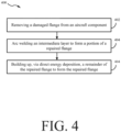
- FIG. 4 a flow chart ( FIG. 4 ) of a method 400 method of repairing an aircraft component 500 (e.g., inner case 200 from FIGs. 2 and 3A-B ) and illustrative steps of the method of FIG. 4 ( FIG. 5 ) are illustrated, in accordance with various embodiments.
- the method comprises removing (e.g., via machining or the like) a damaged flange 510 (e.g., axial flange 230 of inner case 200 from FIGs. 3A and 3B ) from the aircraft component 500 (step 402).
- the aircraft component 500 includes a metal alloy (e.g., 718 as described previously herein).
- the aircraft component 500 is originally formed by casting.
- the aircraft component 500 can be susceptible to liquation cracking if exposed directly to a DED laser, in accordance with various embodiments.
- the base surface 512 can be flush with a surface 502 defined by the aircraft component (e.g., by a radial flange 220 of the inner case 200 as shown in FIG. 3A ).
- the arc welding is one of gas tungsten arc welding ("GTAW'), shield metal arc welding (“SMA”), plasma arc welding ("PAW").
- the method 400 further comprises building up, via direct energy deposition, a remainder of the repaired flange 540 (e.g., a repaired wall for the case 200 from FIG. 3A to replace the axial flange 230, i.e., a damaged flange) with a second material to form a remainder portion 530 of the repaired flange 540 (step 406).
- the first material has a lower strength relative to the second material.
- a base material of the aircraft component 500 e.g., wall 210 of inner case 200 from FIG. 3A
- the second material is different from the first material.
- references to "one embodiment,” “an embodiment,” “various embodiments,” etc. indicate that the embodiment described may include a particular feature, structure, or characteristic, but every embodiment may not necessarily include the feature, structure, or characteristic. Moreover, such phrases are not necessarily referring to the same embodiment. Further, when a particular feature, structure, or characteristic is described in connection with an embodiment, it is submitted that it is within the knowledge of one skilled in the art to affect such feature, structure, or characteristic in connection with other embodiments whether explicitly described. After reading the description, it will be apparent to one skilled in the relevant art(s) how to implement the disclosure in alternative embodiments.
Landscapes
- Engineering & Computer Science (AREA)
- Chemical & Material Sciences (AREA)
- Mechanical Engineering (AREA)
- Materials Engineering (AREA)
- Manufacturing & Machinery (AREA)
- Organic Chemistry (AREA)
- Metallurgy (AREA)
- Physics & Mathematics (AREA)
- Plasma & Fusion (AREA)
- Composite Materials (AREA)
- Optics & Photonics (AREA)
- General Engineering & Computer Science (AREA)
- Arc Welding In General (AREA)
- Working Measures On Existing Buildindgs (AREA)
Applications Claiming Priority (1)
| Application Number | Priority Date | Filing Date | Title |
|---|---|---|---|
| US18/326,908 US20240399452A1 (en) | 2023-05-31 | 2023-05-31 | Hybrid additive manufacturing repair method |
Publications (2)
| Publication Number | Publication Date |
|---|---|
| EP4470714A2 true EP4470714A2 (fr) | 2024-12-04 |
| EP4470714A3 EP4470714A3 (fr) | 2025-01-01 |
Family
ID=91193508
Family Applications (1)
| Application Number | Title | Priority Date | Filing Date |
|---|---|---|---|
| EP24177170.8A Pending EP4470714A3 (fr) | 2023-05-31 | 2024-05-21 | Procédé de réparation de fabrication additive hybride |
Country Status (2)
| Country | Link |
|---|---|
| US (1) | US20240399452A1 (fr) |
| EP (1) | EP4470714A3 (fr) |
Family Cites Families (11)
| Publication number | Priority date | Publication date | Assignee | Title |
|---|---|---|---|---|
| US20100236067A1 (en) * | 2006-08-01 | 2010-09-23 | Honeywell International, Inc. | Hybrid welding repair of gas turbine superalloy components |
| EP2546021A1 (fr) * | 2011-07-12 | 2013-01-16 | Siemens Aktiengesellschaft | Alliage à base de nickel, utilisation et procédé de fabrication |
| JP2013068085A (ja) * | 2011-09-20 | 2013-04-18 | Toshiba Corp | スキーラ付きガスタービン動翼の補修方法 |
| US20140017415A1 (en) * | 2012-07-13 | 2014-01-16 | General Electric Company | Coating/repairing process using electrospark with psp rod |
| DE102013214781B3 (de) * | 2013-07-29 | 2015-02-26 | MTU Aero Engines AG | Verfahren zur Reparatur eines Aufnahmehakens für Leitschaufeln |
| US20190217411A1 (en) * | 2018-01-12 | 2019-07-18 | Pratt & Whitney Canada Corp. | Method for repairing magnesium castings |
| US20220143759A1 (en) * | 2019-02-25 | 2022-05-12 | The Chugoku Electric Power Co., Inc. | Precipitation-strengthened cast product welding repair method |
| US11015459B2 (en) * | 2019-10-10 | 2021-05-25 | Power Systems Mfg., Llc | Additive manufacturing optimized first stage vane |
| JP6734462B1 (ja) * | 2019-12-23 | 2020-08-05 | 三菱日立パワーシステムズ株式会社 | 翼の補修方法、翼、及びガスタービン |
| US11712738B2 (en) * | 2021-01-28 | 2023-08-01 | Siemens Energy, Inc. | Crack healing additive manufacturing of a superalloy component |
| CN113458605A (zh) * | 2021-07-12 | 2021-10-01 | 南京航空航天大学 | 一种基于激光-mig复合增材修复的装置与方法 |
-
2023
- 2023-05-31 US US18/326,908 patent/US20240399452A1/en active Pending
-
2024
- 2024-05-21 EP EP24177170.8A patent/EP4470714A3/fr active Pending
Also Published As
| Publication number | Publication date |
|---|---|
| US20240399452A1 (en) | 2024-12-05 |
| EP4470714A3 (fr) | 2025-01-01 |
Similar Documents
| Publication | Publication Date | Title |
|---|---|---|
| EP1354656B1 (fr) | Méthode de préparation d'un élément de turbine à gaz rechargé | |
| EP1526252B1 (fr) | Procédé de production d'un rotor de turbine avec des propriétés triples | |
| US9951632B2 (en) | Hybrid bonded turbine rotors and methods for manufacturing the same | |
| US4743165A (en) | Drum rotors for gas turbine engines | |
| EP4105438A1 (fr) | Méthode de collage pour la réparation d'un article en superalliage | |
| EP2298489A1 (fr) | Composition de superalliage et procédé de formation d'un composant de moteur à turbine | |
| JP4731002B2 (ja) | 超合金溶接組成物及び補修タービンエンジン部品 | |
| EP2045443A2 (fr) | Disque de rotor d'une turbomachine et son procédé de fabrication | |
| EP2113634B1 (fr) | Procédé de réparation d' un carter de moteur à turbine à gaz doté d'une bride remplacée en utilisant un transfert de métal à froid | |
| EP3848142B1 (fr) | Pièce en superalliage et procédé de traitement | |
| JP2001158929A (ja) | 超合金溶接組成物および修復されたタービンエンジン部品 | |
| GB2559325A (en) | Bladed disc and method of manufacturing the same | |
| EP2412930B1 (fr) | Segment statorique de turbine et son procédé de réparation | |
| EP4470714A2 (fr) | Procédé de réparation de fabrication additive hybride | |
| Ellison et al. | Powder metallurgy repair of turbine components | |
| US10294804B2 (en) | Dual alloy gas turbine engine rotors and methods for the manufacture thereof | |
| US20250018488A1 (en) | Braze repair | |
| US20230050740A1 (en) | Weld-brazing techniques | |
| EP4592022A2 (fr) | Réparation de fabrication additive hybride avec caractéristique de fusion de lit de poudre et jonction de dépôt d'énergie dirigée | |
| Arjakine et al. | Advanced weld repair of gas turbine hot section components | |
| US20180209288A1 (en) | Braze system, brazed article, and method for forming a brazed article | |
| Chan et al. | Advanced Tip Repair of Single Crystal HPT Blades With LW3 and LW4280 Welding Materials | |
| Frederick et al. | Laser Weld Repair of Service Exposed IN738 and GTD111 Buckets | |
| JPWO2020154453A5 (fr) |
Legal Events
| Date | Code | Title | Description |
|---|---|---|---|
| PUAI | Public reference made under article 153(3) epc to a published international application that has entered the european phase |
Free format text: ORIGINAL CODE: 0009012 |
|
| STAA | Information on the status of an ep patent application or granted ep patent |
Free format text: STATUS: THE APPLICATION HAS BEEN PUBLISHED |
|
| PUAL | Search report despatched |
Free format text: ORIGINAL CODE: 0009013 |
|
| AK | Designated contracting states |
Kind code of ref document: A2 Designated state(s): AL AT BE BG CH CY CZ DE DK EE ES FI FR GB GR HR HU IE IS IT LI LT LU LV MC ME MK MT NL NO PL PT RO RS SE SI SK SM TR |
|
| AK | Designated contracting states |
Kind code of ref document: A3 Designated state(s): AL AT BE BG CH CY CZ DE DK EE ES FI FR GB GR HR HU IE IS IT LI LT LU LV MC ME MK MT NL NO PL PT RO RS SE SI SK SM TR |
|
| RIC1 | Information provided on ipc code assigned before grant |
Ipc: F01D 5/00 20060101ALI20241126BHEP Ipc: B33Y 10/00 20150101ALI20241126BHEP Ipc: B23K 26/342 20140101ALI20241126BHEP Ipc: B23K 9/04 20060101ALI20241126BHEP Ipc: B23P 6/00 20060101AFI20241126BHEP |
|
| STAA | Information on the status of an ep patent application or granted ep patent |
Free format text: STATUS: REQUEST FOR EXAMINATION WAS MADE |
|
| 17P | Request for examination filed |
Effective date: 20250701 |