EP4470520A1 - System zur stimulation des menschlichen körpers mit schwingungen unter verwendung von akustischem druck und knochenleitungsgeräusch unter verwendung von photoakustischem schall - Google Patents
System zur stimulation des menschlichen körpers mit schwingungen unter verwendung von akustischem druck und knochenleitungsgeräusch unter verwendung von photoakustischem schall Download PDFInfo
- Publication number
- EP4470520A1 EP4470520A1 EP22924292.0A EP22924292A EP4470520A1 EP 4470520 A1 EP4470520 A1 EP 4470520A1 EP 22924292 A EP22924292 A EP 22924292A EP 4470520 A1 EP4470520 A1 EP 4470520A1
- Authority
- EP
- European Patent Office
- Prior art keywords
- sound
- vibration
- human body
- vibrations
- bone conduction
- Prior art date
- Legal status (The legal status is an assumption and is not a legal conclusion. Google has not performed a legal analysis and makes no representation as to the accuracy of the status listed.)
- Pending
Links
Images


Classifications
-
- H—ELECTRICITY
- H04—ELECTRIC COMMUNICATION TECHNIQUE
- H04R—LOUDSPEAKERS, MICROPHONES, GRAMOPHONE PICK-UPS OR LIKE ACOUSTIC ELECTROMECHANICAL TRANSDUCERS; ELECTRIC HEARING AIDS; PUBLIC ADDRESS SYSTEMS
- H04R23/00—Transducers other than those covered by groups H04R9/00 - H04R21/00
- H04R23/008—Transducers other than those covered by groups H04R9/00 - H04R21/00 using optical signals for detecting or generating sound
-
- A—HUMAN NECESSITIES
- A61—MEDICAL OR VETERINARY SCIENCE; HYGIENE
- A61H—PHYSICAL THERAPY APPARATUS, e.g. DEVICES FOR LOCATING OR STIMULATING REFLEX POINTS IN THE BODY; ARTIFICIAL RESPIRATION; MASSAGE; BATHING DEVICES FOR SPECIAL THERAPEUTIC OR HYGIENIC PURPOSES OR SPECIFIC PARTS OF THE BODY
- A61H23/00—Percussion or vibration massage, e.g. using supersonic vibration; Suction-vibration massage; Massage with moving diaphragms
- A61H23/02—Percussion or vibration massage, e.g. using supersonic vibration; Suction-vibration massage; Massage with moving diaphragms with electric or magnetic drive
- A61H23/0218—Percussion or vibration massage, e.g. using supersonic vibration; Suction-vibration massage; Massage with moving diaphragms with electric or magnetic drive with alternating magnetic fields producing a translating or oscillating movement
- A61H23/0236—Percussion or vibration massage, e.g. using supersonic vibration; Suction-vibration massage; Massage with moving diaphragms with electric or magnetic drive with alternating magnetic fields producing a translating or oscillating movement using sonic waves, e.g. using loudspeakers
-
- A—HUMAN NECESSITIES
- A61—MEDICAL OR VETERINARY SCIENCE; HYGIENE
- A61H—PHYSICAL THERAPY APPARATUS, e.g. DEVICES FOR LOCATING OR STIMULATING REFLEX POINTS IN THE BODY; ARTIFICIAL RESPIRATION; MASSAGE; BATHING DEVICES FOR SPECIAL THERAPEUTIC OR HYGIENIC PURPOSES OR SPECIFIC PARTS OF THE BODY
- A61H23/00—Percussion or vibration massage, e.g. using supersonic vibration; Suction-vibration massage; Massage with moving diaphragms
- A61H23/02—Percussion or vibration massage, e.g. using supersonic vibration; Suction-vibration massage; Massage with moving diaphragms with electric or magnetic drive
-
- A—HUMAN NECESSITIES
- A61—MEDICAL OR VETERINARY SCIENCE; HYGIENE
- A61H—PHYSICAL THERAPY APPARATUS, e.g. DEVICES FOR LOCATING OR STIMULATING REFLEX POINTS IN THE BODY; ARTIFICIAL RESPIRATION; MASSAGE; BATHING DEVICES FOR SPECIAL THERAPEUTIC OR HYGIENIC PURPOSES OR SPECIFIC PARTS OF THE BODY
- A61H2201/00—Characteristics of apparatus not provided for in the preceding codes
- A61H2201/10—Characteristics of apparatus not provided for in the preceding codes with further special therapeutic means, e.g. electrotherapy, magneto therapy or radiation therapy, chromo therapy, infrared or ultraviolet therapy
-
- A—HUMAN NECESSITIES
- A61—MEDICAL OR VETERINARY SCIENCE; HYGIENE
- A61H—PHYSICAL THERAPY APPARATUS, e.g. DEVICES FOR LOCATING OR STIMULATING REFLEX POINTS IN THE BODY; ARTIFICIAL RESPIRATION; MASSAGE; BATHING DEVICES FOR SPECIAL THERAPEUTIC OR HYGIENIC PURPOSES OR SPECIFIC PARTS OF THE BODY
- A61H2201/00—Characteristics of apparatus not provided for in the preceding codes
- A61H2201/16—Physical interface with patient
- A61H2201/1683—Surface of interface
- A61H2201/1685—Surface of interface interchangeable
-
- A—HUMAN NECESSITIES
- A61—MEDICAL OR VETERINARY SCIENCE; HYGIENE
- A61H—PHYSICAL THERAPY APPARATUS, e.g. DEVICES FOR LOCATING OR STIMULATING REFLEX POINTS IN THE BODY; ARTIFICIAL RESPIRATION; MASSAGE; BATHING DEVICES FOR SPECIAL THERAPEUTIC OR HYGIENIC PURPOSES OR SPECIFIC PARTS OF THE BODY
- A61H2201/00—Characteristics of apparatus not provided for in the preceding codes
- A61H2201/50—Control means thereof
- A61H2201/5005—Control means thereof for controlling frequency distribution, modulation or interference of a driving signal
-
- H—ELECTRICITY
- H01—ELECTRIC ELEMENTS
- H01F—MAGNETS; INDUCTANCES; TRANSFORMERS; SELECTION OF MATERIALS FOR THEIR MAGNETIC PROPERTIES
- H01F7/00—Magnets
- H01F7/02—Permanent magnets [PM]
- H01F7/0273—Magnetic circuits with PM for magnetic field generation
- H01F7/0289—Transducers, loudspeakers, moving coil arrangements
-
- H—ELECTRICITY
- H01—ELECTRIC ELEMENTS
- H01F—MAGNETS; INDUCTANCES; TRANSFORMERS; SELECTION OF MATERIALS FOR THEIR MAGNETIC PROPERTIES
- H01F7/00—Magnets
- H01F7/06—Electromagnets; Actuators including electromagnets
- H01F7/066—Electromagnets with movable winding
-
- H—ELECTRICITY
- H04—ELECTRIC COMMUNICATION TECHNIQUE
- H04R—LOUDSPEAKERS, MICROPHONES, GRAMOPHONE PICK-UPS OR LIKE ACOUSTIC ELECTROMECHANICAL TRANSDUCERS; ELECTRIC HEARING AIDS; PUBLIC ADDRESS SYSTEMS
- H04R2460/00—Details of hearing devices, i.e. of ear- or headphones covered by H04R1/10 or H04R5/033 but not provided for in any of their subgroups, or of hearing aids covered by H04R25/00 but not provided for in any of its subgroups
- H04R2460/13—Hearing devices using bone conduction transducers
-
- H—ELECTRICITY
- H04—ELECTRIC COMMUNICATION TECHNIQUE
- H04R—LOUDSPEAKERS, MICROPHONES, GRAMOPHONE PICK-UPS OR LIKE ACOUSTIC ELECTROMECHANICAL TRANSDUCERS; ELECTRIC HEARING AIDS; PUBLIC ADDRESS SYSTEMS
- H04R9/00—Transducers of moving-coil, moving-strip, or moving-wire type
- H04R9/02—Details
- H04R9/025—Magnetic circuit
Definitions
- the present invention relates to a human body stimulation system providing vibrations using acoustic pressure and bone conduction sound using photoacoustic sound.
- the present invention relates to a human body stimulation system providing vibrations using acoustic pressure and bone conduction sound using photoacoustic sound, wherein the system comprises: a vibration device configured to provide vibrations using acoustic pressure to the human body; and a transducer providing bone conduction sound using photoacoustic sound, and thus can provide vibrations (tactile sensations) and bone conduction sound (auditory sensations) to the human body (especially the brain).
- bone conduction sound can be provided simultaneously with human body stimulation for vibrations.
- Such stimulation devices include massage devices.
- a massage device is a device that massages by stimulating the skin or scalp while tapping or rubbing the skin or scalp to achieve smooth blood circulation, promote fat decomposition, and discharge waste.
- Such massage devices generate vibrations or electrical stimulation using electrical signals and apply them to the skin or scalp.
- massage devices include low-frequency massage devices that massage by passing low-frequency current through the human body via electrodes attached to the skin surface, ultrasonic massage devices that deliver ultrasonic vibrations to the human body by placing an ultrasonic irradiation probe in contact with the skin surface, and massage devices that employ ultra- low frequencies or far-infrared rays, and the like.
- the high-frequency technologies are intended for deep heat rather than for stimulating device, and thus, have an inherent risk factor for the user due to the characteristics of high frequency as well as the user's anxiety.
- they require the exposure of affected areas and a medium for transmission in use, as well as, they utilize conductive plates for transmission of both poles of electricity, so they are not only dangerous but also cause many inconvenience in use.
- Low-frequency therapeutic devices had problems that they continuously and repeatedly apply low-frequency current in the form of low-frequency pulses to the skin through electrodes, generating a sensation similar to an electric shock, which makes the treatment unpleasant and halves the therapeutic effects. Additionally, the low-frequency therapeutic devices had problems that the affected areas must be exposed in order to attach the electrodes to the skin, which makes the female users avoid these devices and the like.
- the ultrasound treatment and beauty devices had various problems, including that: the ultrasound vibrations propagate when the skin contact surface of the ultrasound irradiation probe touches the skin, but if the probe is placed incorrectly on the skin, the ultrasound vibrations do not propagate, resulting in unsatisfactory effects, and regardless of whether the probe makes good contact with the skin, since the ultrasound output set by the user is irradiated, the vibration propagating part of the probe generates heat by the vibration in the case of non-contact, which increases the temperature of this part, causing discomfort to the user, a risk of burns if used for a long time, and the like.
- various skin care modes can be implemented by using a vibrator that vibrates vertically by a magnetic coil method, and various technologies have been disclosed for galvanic massage and iontophoresis massage using said vibrator.
- the object of the present invention relates to a human body stimulation system providing vibrations using acoustic pressure and bone conduction sound using photoacoustic sound, wherein the system comprises: a vibration device configured to provide vibrations using acoustic pressure to the human body; and a transducer providing bone conduction sound using photoacoustic sound, and thus can provide vibrations (tactile sensations) and bone conduction sound (auditory sensations) to the human body (especially the brain).
- the human body stimulation system providing vibrations using acoustic pressure and bone conduction sound using photoacoustic sound comprises: a human body stimulation device (200) providing vibrations using acoustic pressure to the human body through a vibration device (100); and a bone conduction sound generating device (300) providing bone conduction sound using photoacoustic sound through a transducer (400); wherein the human body stimulation system is characterized in that it can provide vibrations and bone conduction sound simultaneously to the human body, thereby enhancing the effects of human body stimulation.
- the human body stimulation system providing vibrations using acoustic pressure and bone conduction sound using photoacoustic sound according to the present invention, since it can provide a vibration using acoustic pressure and bone conduction sound using photoacoustic sound, and thus can improve the efficiency of human body stimulation and consequently enhance the additional effects on the human body
- the system comprises a vibration device configured to provide vibrations using acoustic pressure to the human body; and a transducer providing bone conduction sound using photoacoustic sound, and thus can provide vibrations (tactile sensations) and bone conduction sound (auditory sensations) to the human body (especially the brain).
- the present invention relates to a human body stimulation system providing vibrations using acoustic pressure and bone conduction sound using photoacoustic sound.
- the present invention relates to a human body stimulation system providing vibrations using acoustic pressure and bone conduction sound using photoacoustic sound, wherein the system comprises: a vibration device configured to provide vibrations using acoustic pressure to the human body; and a transducer providing bone conduction sound using photoacoustic sound, and thus can provide vibrations (tactile sensations) and bone conduction sound (auditory sensations) to the human body (especially the brain).
- bone conduction sound can be provided simultaneously with human body stimulation for vibrations.
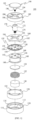
- the present invention is configured to comprise: a vibration device (100); a human body stimulation device (200); and a bone conduction sound generating device (300).
- the vibration device (100) of the present invention comprises: an upper and lower body (110, 180), an upper and lower bracket (120, 160), a magnetic body (130), a voice coil (132), an upper plate (134), a bobbin (140), a congee damper (150), and a connecting member (170).
- the vibration device (100) may also be equipped with a waterproof member or a buffer member, although such is not shown in the drawings.
- the configuration of the vibration device is described in detail for this embodiment using a connecting member (170) for transmitting vibrations and a vibration probe (190) coupled to the connecting member (170) for massaging and stimulating the human body, so as to transmit the vibrations generated from the vibration device (100) to the outside and be able to massage and stimulate the skin or scalp of the human body,
- the vibration probe (190) is detachably equipped to the vibration device (100).
- the vibration probe (190) can have various shapes and sizes to suit the various uses of the human body stimulation device (200 of Fig. 4 ) described later.
- the vibration probe (190) of this embodiment comprises: a plate (192) to which a massage or stimulation head (not shown) is attached and detached, a shaft (194) coupled to the center of the lower surface of the plate (192), and a coupling part (196) provided at the lower end of the shaft (194) to be mutually coupled with the connecting member (170).
- the coupling part (196) is provided in the form of a bolt that is screw coupled with the connecting member (170).
- the above-described vibration probe (190) has a concave groove (1) formed upward on one side of the lower surface where the bolt (176) of the shaft (194) is not formed, and on the groove (1), the vibrating body (2) is coupled to the groove (1) by a connector (4).
- the connector (4) has a two-step shape of " ", and a part of the connector (4) is inserted into and secured in place in the insertion groove (3) formed in the vibrating body (2).
- the size of the insertion groove (3) is made larger than the size of the part of the connector (4) inserted into the insertion groove.
- Fig. 2a shows another embodiment of the vibration device.
- the vibrating body (2) is smaller than the groove (1), allowing the vibrating body to pivot around the connector (4) within the groove (1).
- a elastic body (5) is provided between one surface of the groove (1) and the upper surface of the vibrating body (2), and the above-described elastic body (5) can be referred to in Fig. 2b of the attached drawings.
- Fig. 2b is an enlarged view of the elastic body of Fig. 2a .
- the elastic body (5) according to Fig. 2b of the attached drawings has a cylindrical shape with a hollow inside and symmetrically extending a first wing (52) and a second wing (53) on both sides, and comprises: a first shaft (51) having two guide grooves (54) formed along the longitudinal direction on one side and that is open at one end;
- the second shaft (55) is inserted into the hollow of the first shaft (51) as the third wing (56) and fourth wing (57) are inserted and guided into each of the guide grooves (54) of the first shaft (51).
- a torsion spring is inserted through the insertion groove (56a, 57a) as shown in Fig. 2b , with one protruding end of the torsion spring being secured in place in close contact with one surface of the third wing (56), and the other protruding end in the other direction being secured in place in close contact with one surface of the second wing (53).
- the said elastic body (50) can be operated to fold to the extent that the third wing (56) and fourth wing (57) can move from the guide grooves (54), while having an "X" shape due to the elastic force of the torsion spring.
- the shaft (194) of the vibration probe (190) according to the present invention has the effects of increasing the intensity of vibration mode by the vibrating body (2), and also reducing the impact due to the vibration applied to the probe itself even when the intensity of vibration increases by the elastic body (5).
- the vibrating body (2) includes an inclined surface slanted in a predetermined direction on the lower surface as shown in Fig. 2a of the attached drawings, and thus, allowing the vibrating body (2) to pivot without being affected by the upper surface of the connecting member (170) corresponding to the lower surface of the groove (1).
- the embodiment of this lower surface may have a wedge or cone shape different from the attached drawings.
- the lower body (110) is equipped with a cylindrical shape having an open top part, forming a space where the magnetic body (130) is installed inside.
- the magnetic body (130) is fixedly installed on the bottom surface of the inner space of the lower body (110).
- the lower bracket (120) is insert installed outside the magnetic body (130) in the inner space of the lower body (110).
- the lower body (110) is equipped with a securing groove (112) formed on the bottom surface where the magnetic body (130) is fixedly installed, , a ring-shaped separation groove (114) equipped to be spaced a certain distance from the outer circumferential surface of the magnetic body (130) secured in the securing groove (112), and a ring-shaped mounting groove (116) where the lower bracket (120) is mounted to be spaced a certain distance from the magnetic body (130).
- a separation groove (114) is equipped to form the magnetic path created by the magnetic body (130) and the voice coil (132).
- the upper body (180) is equipped with a cylindrical shape having an open bottom, covering the open top of the lower body (110).
- the upper body (180) is coupled to the lower body (110), forming a space to accommodate components (120-160) inside.
- the upper surface (182) of the upper body (180) is formed with an insertion hole (184) through which the shaft (194) of the connecting member (170) and the vibration probe (190) are inserted to pass through the center, and a plurality of heat dissipation holes (186) provided outside the insertion hole (184) to release heat generated during the vibration of the vibration device (100).
- the upper surface (182) of the upper body (180) may further be equipped with, for example, a waterproof member (not shown), such as silicone, etc., for waterproofing the insertion hole (184) where the vibration probe (190) is inserted.
- a waterproof member such as silicone, etc.
- the upper body (180) and lower body (110) are made of aluminum to enhance the heat dissipation effect.
- the lower bracket (120) is equipped with a cylindrical shape with an open top and bottom.
- the lower bracket (120) is installed in the mounting groove (116) of the lower body (110), and its upper surface is coupled with the congee damper (170).
- the lower bracket (120) is equipped with a plurality of coupling protrusions (122) on its upper surface.
- a bobbin (140) with a voice coil (132) mounted on it is installed inside the lower bracket (120. Apart of the lower bracket (120) protrudes to the upper part of the lower body (110).
- the coupling protrusions (122) of the lower bracket (120) may be further secured by using a silicone washer, etc., for ensuring durability and maintaining the vibration force upon coupling with the damper (158) of the congee damper (150).
- a silicone washer can be selectively used to adjust the height of the congee damper (150) according to frequency properties, thereby performing the function for maintaining efficient amplitude.
- the upper bracket (160) is equipped with a plate shape to be accommodated inside the upper body (180), and its edge is coupled with the upper part of the lower bracket (120).
- the lower surface of the edge of the upper bracket (160) is equipped with a plurality of coupling protrusions (162) to couple the congee damper (150) and the lower bracket (120).
- the upper surface of the upper bracket (160) is equipped with a generally circular shape and faces the lower bracket (120).
- the upper surface of the upper bracket (160) is formed with an insertion hole (164) through which the connecting member (170) is inserted to pass through the center, and a plurality of heat dissipation holes (166) equipped outside the insertion hole (164) to release heat generated during the vibration of the vibration device (100).
- These insertion holes (184, 164) of the upper body (180) and the upper bracket (160) secure the connecting member (170) and the vibration probe (190) to the center of the vibration device (100).
- a buffer member such as a plate spring, etc., may be further equipped between the upper surface of the upper bracket (160) and the upper body (180) to prevent unnecessary vibration transmission.
- the magnetic body (130) is fixedly installed in the securing groove (112) of the lower body (110) and interacts with the voice coil (132) to generate a magnetic field.
- the magnetic body (130) is equipped as a permanent magnet of a ferromagnetic material, such as a neodymium magnet, etc.
- An upper plate (134) is installed on the upper surface of the magnetic body (130).
- the voice coil (132) is installed on the outer circumferential surface of the bobbin (140) above the magnetic body (130).
- the voice coil (132) is guided to be stably installed by the bobbin (140).
- the voice coil (132) receives power and interacts with the magnetic body (130) to generate a magnetic field.
- the magnetic body (130) and the voice coil (132) are installed inside the lower bracket (120).
- the upper plate (134) has a shape that is generally similar to the upper surface of the magnetic body (130), is equipped on the upper part of the magnetic body (130), and is installed adjacent to the lower surface of the bobbin (140).
- the upper plate (134) guides the magnetic force of the magnetic body (130) to be concentrated on the voice coil (132) to prevent the loss of the magnetic field generated by the magnetic body (130).
- the upper plate (134) may be applied with a magnetic fluid (not shown) on its outer circumference to form a magnetic field.
- the bobbin (140) is provided as a non-magnetic material, such as aluminum, etc.
- the bobbin (140) is installed inside the lower bracket (120).
- the bobbin (140) guides the voice coil (132) to be stably installed on its outer side, preventing the voice coil (132) from coming off.
- the bobbin (140) is coupled to the connecting member (170) at the center of its upper surface.
- the bobbin (140) is equipped with a cylindrical shape with open upper and lower sides, the upper surface (142) being larger than the radius of the side, and the lower side extending outward to have a lower surface (148) facing the upper surface (142).
- the voice coil (132) is installed on the side of the bobbin (140). At this time, the voice coil (132) is guided by the upper surface (142) and the lower surface (148) of the bobbin (140).
- the upper surface (142) of the bobbin (140) is formed with a coupling hole (144) at the center to couple with the lower end of the connecting member (170), and a plurality of heat dissipation holes (146) equipped outside the coupling hole (144) to release heat generated when the vibration device (100) vibrates.
- These heat dissipation holes (146) function to reduce noise upon occurring vibration along with the heat dissipation effect. Additionally, the bobbin (140) releases the heat generated from the voice coil (132).
- the magnetic body (130) is secured in place in the securing groove (112) of the lower body (110), and is positioned on the inner circumference of the lower surface (148) of the bobbin (140), creating an efficient magnetic field.
- the voice coil (132) wound around the bobbin (140) is magnetized, it generates mutual attraction and repulsion forces, producing stable vibration force.
- the vibration probe (190) is coupled through the connecting member (170), it serves as that even if physical eccentricity occurs when the human body is stimulated by the vibration probe (190), the strong magnetic path created by the coupling of the magnetic body (130) and the upper plate (134) corrects the eccentricity in the bobbin (140).
- the congee damper (150) is installed on the upper surface (142) of the bobbin (140), generating vertical vibrations using the magnetic field created by the interaction between the magnetic body (130) and the voice coil (132). That is, the congee damper (150) generates vibrations by acting like a speaker on the sound of the sound source, wherein the vibrations from the sound source cause the air to oscillate.
- the congee damper (150) is coupled with the upper and lower brackets (120, 160) at its edges.
- the congee damper (150) includes a congee plate (152) and a plurality of dampers (158).
- the congee plate (152) is formed with a coupling hole (154) at the center to couple with the lower end of the connecting member (170), and a plurality of heat dissipation holes (156) are formed outside the coupling hole (154).
- Each of dampers (158) is equipped in a radially elongated curved strip shape on the congee plate (152) to maximize the vibration force of the congee damper (150), with a coupling hole (159) for screw coupling formed at the end.
- the dampers (158) are screw coupled and secured in place between the coupling protrusions (162) of the upper bracket (160) and the coupling protrusions (122) of the lower bracket (120) by the coupling holes (159).
- the congee damper (150) is supported by elastic members such as silicone washers on the upper and lower parts of the coupling holes (159) of the dampers (158), preventing vibration attenuation and generating smooth sound when the vibration occurs.
- the congee damper (150) generates vibrations in response to changes in the acoustic pressure of the sound source to be supplied from the outside.
- the congee damper (150) is coupled with the connecting member (170) at the center, transmitting vibrations to external components such as the vibration probe (190), etc., through the connecting member (170). Because the central part of the congee damper (150) has the largest vibration amplitude, coupling the bolt (176) of the connecting member (170) with the coupling hole (154) of the congee damper (150) can improve vibration transmission efficiency.
- the connecting member (170) is coupled at the center of the upper surface (142) of the congee damper (150) and the bobbin (140) to enhance the coupling force with the connecting member (170).
- the connecting member (170) directly receives and then transmits the vibrations generated from the congee damper (150) to the outside.
- the connecting member (170) is coupled with the shaft (194) of the vibration probe (190).
- the connecting member (170) is equipped in a shaft shape, with the upper part coupled to the shaft (194) of the vibration probe (190), and the lower part coupled to the upper surface (142) of the congee damper (150) and the bobbin (140).
- the connecting member (170) is equipped with a shaft-shaped body (172), a coupling groove (174) at the upper part of the body (172) for coupling with the shaft (194), and a coupling bolt (176) at the lower part of the body (172) for coupling with the coupling hole (154) of the congee damper (150) and the coupling hole (144) of the bobbin (140).
- the inside of the coupling hole (174) has a structure where the coupling part (196) of the shaft (194) is screw coupled.
- the shaft (194) of the vibration probe (190) is inserted through the center of the upper body (180) and coupled with the connecting member (170), and the connecting member (170) is inserted through the upper bracket (160) and screw coupled to the center of the congee damper (150) and the bobbin (140).
- the vibrations are transmitted to the vibration probe (190) through the connecting member (170) coupled to the congee damper (170).
- FIG. 3 Another embodiment of the connecting member (170) is shown in Fig. 3 .
- the vibration probe (190a) is formed with a securing groove (198) at a specific position along the outer circumferential surface of the shaft (194a).
- the securing groove (198) is formed, for example, on the outer circumferential surface of the part where the shaft (194a) of the vibration probe (190a) is inserted into the coupling groove (174) of the connecting member (170a).
- the securing groove (125) is formed with a locking step at the upper part and a guide part formed at the lower part.
- a elastic securing pin (178) inserted into the securing groove (198) is fixedly mounted on the connecting member (170a).
- the elastic securing pin (178) is fixedly coupled on the outer side of the connecting member (170a), with a part exposed inside the coupling groove (174) of the connecting member (170a), and the exposed part is seated in or separated from the securing groove (198) of the shaft (194a).
- This connecting member (170a) guides the elastic securing pin (178) to be seated in the securing groove (198) by the guide part of the securing groove (198) when the shaft (194a) of the vibration probe (190a) is pressed downward and inserted into the coupling groove (174), and the elastic securing pin (178) is fixedly mounted in by the locking step at the same time. Additionally, with respect to the connecting member (170a), when the shaft (194a) is pressed upward and separated from the coupling groove (174), the elastic securing pin (178) is easily detached from the securing groove (178) by the guide part of the securing groove (198).
- the vibration probe (190a) can be more easily coupled with and separated from the connecting member (170) compared to the screw-coupled structure of Figs. 1 and 2 , and it can prevent damage to the coupling part (196) of the vibration probe (190) that may occur due to several times of coupling and separation of the vibration probe (190a) with the vibration device (100).
- the vibration probe (190, 190a) of the present invention is easy to assemble during manufacturing as it uses a connecting member (170, 170a) that is coupled using screw coupling or a securing groove (198) and a elastic securing pin (178).
- the vibration device (100) of the present invention directly receives vibrations from the center of the congee damper (150) by coupling the connecting member (170, 170a) and the shaft (194, 194a) of the vibration probe (190, 190a) to the center of the congee damper (150), which generates vibrations in response to changes in the acoustic pressure of the sound source. Additionally, the vibration device (100) of the present invention improves the coupling force with the connecting member by coupling the connecting member (170) and the shaft (194, 194a) of the vibration probe (190, 190a) to the center of the upper surface (142) of the bobbin (140) along with the congee damper (150), thereby being able to enhance vibration transmission efficiency.
- the vibration device (100) of the present invention can improve vibration generation efficiency as it is configured with a congee plate (152) that functions to generate sound waves on the congee damper (150) in the shape of a plate springs and a damper (158) that functions to transmit vibration force and act as a spring, doing so to generate vibrations stably.
- the vibration device (100) of the present invention is described as having a structure with upper and lower bodies (110, 180) and upper and lower brackets (120, 160), it can be implemented without the upper body (180) and upper bracket (160) to simplify the structure and improve vibration generation efficiency and heat dissipation effect. This is because the connecting member (170) is coupled to the upper surface (142) of the congee damper (150) and the bobbin (140), ensuring a firm coupling with the vibration probe (190).
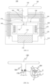
- the human body stimulation device (200) of the present invention uses the vibration device (100) of Fig. 1 or Fig. 3 to receive vibrations generated in response to changes in the acoustic pressure of the sound source and provide massage or stimulation to the human body.
- the human body stimulation device (200) comprises: a sound source processing unit (210), an acoustic pressure generating unit (250) equipping with the vibration device (100), a vibration probe (190) that transmits the vibrations generated by the acoustic pressure generating unit (250) to the outside, and various types of vibration stimulation units (260-266) equipped for use in massage and stimulation.
- the sound source processing unit (210) is equipped inside with devices (not shown) for sound source playback, such as codecs, amplifiers, and speakers, etc., and processes the sound source so that the vibration device (100) generates vibrations using the sound source. Additionally, the sound source processing unit (210) outputs sound wave signals corresponding to the sound source to the acoustic pressure generating unit (250).
- the sound source processing unit (210) of this embodiment comprises: a control unit (202), an input unit (212, 230-236), an output unit (218), an adjustment unit (214, 216), a display unit (206), and a power supply unit (204).
- the input unit (212, 230-236) comprises: a power switch (212) for supplying and cutting off power, and various interface devices for inputting sound sources to the sound source processing unit (210), such as a memory card input unit (230), a USB input unit (232), an AUX input unit (234), a wireless communication input unit (236), and the like.
- the memory card input unit (230) allows various portable storage media on which sound sources are stored, such as SD cards, CF cards, memory sticks, MMC cards, smart media, etc., to be inserted to input sound sources to the sound source processing unit (210).
- a USB input unit (232) connects to an external USB device, such as an MP3 player, smartphone, personal digital assistant (PDAs), portable multimedia player (PMP), USB memory, and the like, and inputs sound sources.
- An AUX input unit (234) inputs sound sources using wired communication.
- a wireless communication input unit (236) receives sound sources from external or wireless internet using, for example, a Wi-Fi network, Bluetooth wireless network, and the like. Therefore, the sound source processing unit (210) accepts sound sources desired or preferred by the user by means of various interface devices, processes the sound sources, and outputs sound wave signals.
- the output unit (218) outputs the sound wave signals generated by processing the sound sources to the acoustic pressure generating unit (250).
- the output unit (218) is connected to the acoustic pressure generating unit (250) through a connector and a connection cable (242).
- the control unit (214, 216) comprises: an intensity control unit (214) and a frequency control unit (216), which are equipped in the form of buttons or dial knobs.
- the intensity control unit (214) adjusts the intensity of the acoustic pressure generated from the input internal or external sound source.
- the frequency control unit (216) adjusts the key, i.e., the frequency, of the built-in sound source.
- the display unit (206) is equipped with, for example, a light-emitting diode or a liquid crystal display panel of the sound source processing unit (210), and displays the operating status of the sound source processing unit (210), such as power on/off status, sound source playback status, control status, and the like.
- the power supply unit (204) receives AC power through the power input unit (220) and supplies power (V) to the sound source processing unit (210).
- control unit (202) controls and processes all the operations of the sound source processing unit (210).
- the control unit (202) controls the power supply from the power supply unit (204) when the power switch (212) is pressed.
- the control unit (202) processes the input of the sound source from the input unit (230-236) and processes the output of the sound wave signal to the output unit (218).
- the control unit (202) processes the playback of the sound source in response to the adjustment of the acoustic pressure intensity or frequency by the intensity control unit (214) and the frequency control unit (216). Additionally, the control unit (202) controls so as to display the operating status of the sound source processing unit (210) through the display unit (206).
- the acoustic pressure generating unit (250) is provided as a handle (240) type and includes a vibration device (100) inside.
- the acoustic pressure generating unit (250) receives the sound wave signal from the output unit (218) of the sound source processing unit (210) and generates vibrations in response to the acoustic pressure variations of the sound wave signal using the vibration device (100).
- This acoustic pressure generating unit (250) transmits vibrations based on pressure applied through direct contact with specific parts of the human body by the mounted vibration probe (190, 260-266) while holding the handle (240). At this time, one of the various vibration probes (190, 260-266) is selected and coupled to the acoustic pressure generating unit (250).
- the vibration probe (190) is coupled to the vibration device (100) of the acoustic pressure generating unit (250) and transmits the vibrations to the vibration stimulation unit (260-266).
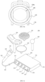
- the vibration stimulation unit (260-266) is provided in various forms to allow the human body stimulation device (200) to massage or stimulate the human body for various uses.
- the vibration stimulation unit (260-266), like the vibration probe (190), is mounted on or detached from the vibration device (100) of the acoustic pressure generating unit (250).
- the vibration stimulation unit (260-266) is provided in various forms depending on the massage area, stimulation area, or usage purpose on the human body, and one of them is selected and mounted on the acoustic pressure generating unit (250).
- the vibration stimulation unit (260-266) can be equipped, for example, with a sound wave transmission probe (260) for electrical stimulation, a vibration probe (262) for scalp massage, a vibration probe (264) for skin massage, a vibration probe (266) for hand and foot massage, and the like.
- the vibration stimulation unit (260-266) can be equipped as a detachable head on the vibration probe (190).
- a plurality of heads are equipped to be used for various uses.
- the heads can be equipped, for example, as a head for skin massage, a head for scalp massage, and a head for hand and foot massage.
- the heads can be made of various materials, such as silicone materials, wood materials, plastic materials, metal materials, and the like.
- Each of these heads is mounted on the vibration probe (190) to transmit the vibrations generated by the vibration device (100) to the human body to massage the skin, scalp, or hands and feet.
- the vibration probe (190) and the vibration stimulation units (260-266) are each coupled to the connecting members (170, 170a) of Fig. 1 or Fig. 3 , and receive vibrations from the congee damper (150) through the connecting member (170, 170a) to provide massage and stimulation to the human body.
- the human body stimulation device (200) of the present invention stimulates the skin or scalp of the human body through various probes (190, 260-266) that receive vibrations from the congee damper (150) generating vibrations using the sound source.
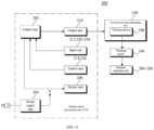
- the bone conduction sound generating device (300) functions to generate bone conduction sound based on a light source so that the system according to the present invention can provide bone conduction sound to the human body through the transducer (400) along with the vibrations using acoustic pressure by the human body stimulation device (200) described above.
- the bone conduction sound generating device (300) comprises: a laser diode (310) providing a light source with a frequency of 100kHz; an optical pulse transmitter (320) including a first pulse generator (321) generating pulses for frequency control of the light source and a second pulse generator (322) generating modulation pulses for pulse frequency modulation; and a laser driver (330) that amplitude modulates the frequency of the light source provided by the laser diode (310) to an audible frequency using the pulses of the optical pulse transmitter (320).
- the frequency range of the amplitude-modulated signal can be 500 Hz, 1 kHz, 2 kHz, 5 kHz, and 10 kHz.
- the laser driver (330) transmits the amplitude-modulated audible frequency to the transducer (400) so that the audible frequency is delivered as bone conduction sound to the wearer's body.
Landscapes
- Health & Medical Sciences (AREA)
- Public Health (AREA)
- Veterinary Medicine (AREA)
- Physical Education & Sports Medicine (AREA)
- Rehabilitation Therapy (AREA)
- Life Sciences & Earth Sciences (AREA)
- Animal Behavior & Ethology (AREA)
- General Health & Medical Sciences (AREA)
- Epidemiology (AREA)
- Pain & Pain Management (AREA)
- Engineering & Computer Science (AREA)
- Physics & Mathematics (AREA)
- Acoustics & Sound (AREA)
- Signal Processing (AREA)
- Percussion Or Vibration Massage (AREA)
- Multimedia (AREA)
- Electromagnetism (AREA)
- Power Engineering (AREA)
Applications Claiming Priority (3)
| Application Number | Priority Date | Filing Date | Title |
|---|---|---|---|
| KR20210090510 | 2021-07-09 | ||
| KR1020220011875A KR102404071B1 (ko) | 2021-07-09 | 2022-01-27 | 음향 압력을 이용한 진동과 광음향을 이용한 골전도 음향을 제공하는 인체자극시스템 |
| PCT/KR2022/008196 WO2023146036A1 (ko) | 2021-07-09 | 2022-06-10 | 음향 압력을 이용한 진동과 광음향을 이용한 골전도 음향을 제공하는 인체자극시스템 |
Publications (2)
| Publication Number | Publication Date |
|---|---|
| EP4470520A1 true EP4470520A1 (de) | 2024-12-04 |
| EP4470520A4 EP4470520A4 (de) | 2025-12-17 |
Family
ID=81987191
Family Applications (1)
| Application Number | Title | Priority Date | Filing Date |
|---|---|---|---|
| EP22924292.0A Pending EP4470520A4 (de) | 2021-07-09 | 2022-06-10 | System zur stimulation des menschlichen körpers mit schwingungen unter verwendung von akustischem druck und knochenleitungsgeräusch unter verwendung von photoakustischem schall |
Country Status (6)
| Country | Link |
|---|---|
| US (1) | US20250205111A1 (de) |
| EP (1) | EP4470520A4 (de) |
| JP (1) | JP2025504574A (de) |
| KR (1) | KR102404071B1 (de) |
| CN (1) | CN118843444A (de) |
| WO (1) | WO2023146036A1 (de) |
Families Citing this family (1)
| Publication number | Priority date | Publication date | Assignee | Title |
|---|---|---|---|---|
| KR102404071B1 (ko) * | 2021-07-09 | 2022-06-07 | 주식회사 아리바이오 | 음향 압력을 이용한 진동과 광음향을 이용한 골전도 음향을 제공하는 인체자극시스템 |
Family Cites Families (12)
| Publication number | Priority date | Publication date | Assignee | Title |
|---|---|---|---|---|
| US4641377A (en) * | 1984-04-06 | 1987-02-03 | Institute Of Gas Technology | Photoacoustic speaker and method |
| KR20040092041A (ko) | 2003-04-23 | 2004-11-03 | (주)트윈 세이버 | 음향 및 저주파를 이용하는 복합 마사지 제공 장치 및 그운용 방법 |
| KR100537687B1 (ko) * | 2003-06-17 | 2005-12-22 | (주)닥터스텍 | 피부 미용장치 |
| KR20080084330A (ko) | 2007-03-16 | 2008-09-19 | 주식회사 홈파워 | 진동발생장치 및 진동발생장치를 이용한 신체자극장치그리고 신체자극장치의 제어방법 |
| KR101394241B1 (ko) | 2011-08-17 | 2014-05-14 | 김정배 | 음향 신호를 이용한 피부 마사지 장치 |
| KR101481740B1 (ko) | 2012-06-27 | 2015-01-15 | 주식회사 비트테라피 | 마사지 장치 |
| KR101297828B1 (ko) * | 2013-04-25 | 2013-08-19 | 주식회사 지티엠 | 골전도 음향장치 |
| KR101487323B1 (ko) * | 2013-08-08 | 2015-01-29 | (주)에보소닉 | 음향 압력을 이용하는 진동 장치 및 이를 구비하는 인체 자극 장치 |
| KR20160001335U (ko) * | 2016-02-15 | 2016-04-25 | 피에스아이 주식회사 | 음파 진동자의 원리를 이용한 두피 마사지기 |
| KR20190103563A (ko) * | 2018-02-28 | 2019-09-05 | 노슨(Nohsn) 주식회사 | 적응형 임피던스 매칭 장치를 포함하는 한방 의료기기 |
| KR102334170B1 (ko) * | 2020-04-01 | 2021-12-02 | 재단법인 대구경북첨단의료산업진흥재단 | 청각 자극이 가능한 골전도 안경 |
| KR102404071B1 (ko) * | 2021-07-09 | 2022-06-07 | 주식회사 아리바이오 | 음향 압력을 이용한 진동과 광음향을 이용한 골전도 음향을 제공하는 인체자극시스템 |
-
2022
- 2022-01-27 KR KR1020220011875A patent/KR102404071B1/ko active Active
- 2022-06-10 EP EP22924292.0A patent/EP4470520A4/de active Pending
- 2022-06-10 CN CN202280093278.0A patent/CN118843444A/zh active Pending
- 2022-06-10 WO PCT/KR2022/008196 patent/WO2023146036A1/ko not_active Ceased
- 2022-06-10 JP JP2024545114A patent/JP2025504574A/ja active Pending
- 2022-10-06 US US18/833,373 patent/US20250205111A1/en active Pending
Also Published As
| Publication number | Publication date |
|---|---|
| CN118843444A (zh) | 2024-10-25 |
| EP4470520A4 (de) | 2025-12-17 |
| US20250205111A1 (en) | 2025-06-26 |
| WO2023146036A1 (ko) | 2023-08-03 |
| KR102404071B1 (ko) | 2022-06-07 |
| JP2025504574A (ja) | 2025-02-12 |
Similar Documents
| Publication | Publication Date | Title |
|---|---|---|
| JP6423879B2 (ja) | 音響圧力を利用する振動装置及びこれを備える人体刺激装置 | |
| KR101470281B1 (ko) | 음향 압력을 이용하는 피부 및 두피 마사지 장치 | |
| US6971984B2 (en) | Magneto-cymatic therapeutic face mask | |
| KR101609989B1 (ko) | 음압을 이용한 인체 자극 장치 | |
| US20250205111A1 (en) | Human body stimulation system providing vibrations using acoustic pressure and bone conduction sound using photoacoustic sound | |
| KR20160064866A (ko) | 음향 압력을 이용한 안마용 마사지 장치 | |
| KR20130068331A (ko) | 휴대폰 결합형 피부 미용 보조 기기 | |
| CN102639093A (zh) | 超声波便秘改善器 | |
| KR101625430B1 (ko) | 음파를 이용한 국소 진동기 | |
| KR20160064894A (ko) | 피부 마사지 장치 및 방법 | |
| KR102620620B1 (ko) | 음향 진동에 의한 촉각 자극과 골전도에 의한 음악을 이용하는 퇴행성 뇌질환용 장치 | |
| CN108498949A (zh) | 一种智能颈椎按摩仪 | |
| KR20040092041A (ko) | 음향 및 저주파를 이용하는 복합 마사지 제공 장치 및 그운용 방법 | |
| KR20190105451A (ko) | 음파 치료 기능이 부가된 고주파 치료기용 전극 유닛 | |
| KR102319852B1 (ko) | 음파 진동 및 공기 압력을 이용한 국소 부위 마사지 장치 및 이를 포함하는 가상 현실에 기반한 음파 진동 장치 | |
| KR20230046774A (ko) | 안마 체어 시스템 | |
| KR20040009619A (ko) | 오디오신호를 이용한 마사지 장치 | |
| KR20140128138A (ko) | 피부 또는 두피 자극 장치 | |
| US20230218480A1 (en) | Electroacoustic Stimulation Device and Method | |
| KR102691055B1 (ko) | 음파 액추에이터를 이용한 인체 자극 장치 | |
| CN211157204U (zh) | 一种音波震动式按摩装置 | |
| KR200293762Y1 (ko) | 오디오신호를 이용한 마사지 장치 | |
| KR200287549Y1 (ko) | 저주파 치료기 | |
| KR20250174780A (ko) | 음악 진동 복부 엘이디 파동 마사지 장치 | |
| WO2022252100A1 (zh) | 一种音波理疗按摩器 |
Legal Events
| Date | Code | Title | Description |
|---|---|---|---|
| STAA | Information on the status of an ep patent application or granted ep patent |
Free format text: STATUS: THE INTERNATIONAL PUBLICATION HAS BEEN MADE |
|
| PUAI | Public reference made under article 153(3) epc to a published international application that has entered the european phase |
Free format text: ORIGINAL CODE: 0009012 |
|
| STAA | Information on the status of an ep patent application or granted ep patent |
Free format text: STATUS: REQUEST FOR EXAMINATION WAS MADE |
|
| 17P | Request for examination filed |
Effective date: 20240814 |
|
| AK | Designated contracting states |
Kind code of ref document: A1 Designated state(s): AL AT BE BG CH CY CZ DE DK EE ES FI FR GB GR HR HU IE IS IT LI LT LU LV MC MK MT NL NO PL PT RO RS SE SI SK SM TR |
|
| DAV | Request for validation of the european patent (deleted) | ||
| DAX | Request for extension of the european patent (deleted) | ||
| A4 | Supplementary search report drawn up and despatched |
Effective date: 20251118 |
|
| RIC1 | Information provided on ipc code assigned before grant |
Ipc: A61H 23/02 20060101AFI20251112BHEP Ipc: H04R 7/02 20060101ALI20251112BHEP Ipc: H04R 7/26 20060101ALI20251112BHEP Ipc: H01F 7/00 20060101ALI20251112BHEP |