EP4469365B1 - Can ends, metal cans and apparatus for dispensing therefrom - Google Patents
Can ends, metal cans and apparatus for dispensing therefrom Download PDFInfo
- Publication number
- EP4469365B1 EP4469365B1 EP23700150.8A EP23700150A EP4469365B1 EP 4469365 B1 EP4469365 B1 EP 4469365B1 EP 23700150 A EP23700150 A EP 23700150A EP 4469365 B1 EP4469365 B1 EP 4469365B1
- Authority
- EP
- European Patent Office
- Prior art keywords
- lid
- score
- dispenser
- features
- panel
- Prior art date
- Legal status (The legal status is an assumption and is not a legal conclusion. Google has not performed a legal analysis and makes no representation as to the accuracy of the status listed.)
- Active
Links
Images


Classifications
-
- B—PERFORMING OPERATIONS; TRANSPORTING
- B65—CONVEYING; PACKING; STORING; HANDLING THIN OR FILAMENTARY MATERIAL
- B65D—CONTAINERS FOR STORAGE OR TRANSPORT OF ARTICLES OR MATERIALS, e.g. BAGS, BARRELS, BOTTLES, BOXES, CANS, CARTONS, CRATES, DRUMS, JARS, TANKS, HOPPERS, FORWARDING CONTAINERS; ACCESSORIES, CLOSURES, OR FITTINGS THEREFOR; PACKAGING ELEMENTS; PACKAGES
- B65D17/00—Rigid or semi-rigid containers specially constructed to be opened by cutting or piercing, or by tearing of frangible members or portions
- B65D17/28—Rigid or semi-rigid containers specially constructed to be opened by cutting or piercing, or by tearing of frangible members or portions at lines or points of weakness
- B65D17/404—Details of the lines of weakness
-
- B—PERFORMING OPERATIONS; TRANSPORTING
- B65—CONVEYING; PACKING; STORING; HANDLING THIN OR FILAMENTARY MATERIAL
- B65D—CONTAINERS FOR STORAGE OR TRANSPORT OF ARTICLES OR MATERIALS, e.g. BAGS, BARRELS, BOTTLES, BOXES, CANS, CARTONS, CRATES, DRUMS, JARS, TANKS, HOPPERS, FORWARDING CONTAINERS; ACCESSORIES, CLOSURES, OR FITTINGS THEREFOR; PACKAGING ELEMENTS; PACKAGES
- B65D17/00—Rigid or semi-rigid containers specially constructed to be opened by cutting or piercing, or by tearing of frangible members or portions
- B65D17/28—Rigid or semi-rigid containers specially constructed to be opened by cutting or piercing, or by tearing of frangible members or portions at lines or points of weakness
- B65D17/32—Rigid or semi-rigid containers specially constructed to be opened by cutting or piercing, or by tearing of frangible members or portions at lines or points of weakness having non-detachable members or portions
-
- B—PERFORMING OPERATIONS; TRANSPORTING
- B05—SPRAYING OR ATOMISING IN GENERAL; APPLYING FLUENT MATERIALS TO SURFACES, IN GENERAL
- B05B—SPRAYING APPARATUS; ATOMISING APPARATUS; NOZZLES
- B05B11/00—Single-unit hand-held apparatus in which flow of contents is produced by the muscular force of the operator at the moment of use
- B05B11/0005—Components or details
- B05B11/0037—Containers
- B05B11/0038—Inner container disposed in an outer shell or outer casing
-
- B—PERFORMING OPERATIONS; TRANSPORTING
- B05—SPRAYING OR ATOMISING IN GENERAL; APPLYING FLUENT MATERIALS TO SURFACES, IN GENERAL
- B05B—SPRAYING APPARATUS; ATOMISING APPARATUS; NOZZLES
- B05B11/00—Single-unit hand-held apparatus in which flow of contents is produced by the muscular force of the operator at the moment of use
- B05B11/0005—Components or details
- B05B11/0037—Containers
- B05B11/0054—Cartridges, i.e. containers specially designed for easy attachment to or easy removal from the rest of the sprayer
-
- B—PERFORMING OPERATIONS; TRANSPORTING
- B05—SPRAYING OR ATOMISING IN GENERAL; APPLYING FLUENT MATERIALS TO SURFACES, IN GENERAL
- B05B—SPRAYING APPARATUS; ATOMISING APPARATUS; NOZZLES
- B05B11/00—Single-unit hand-held apparatus in which flow of contents is produced by the muscular force of the operator at the moment of use
- B05B11/01—Single-unit hand-held apparatus in which flow of contents is produced by the muscular force of the operator at the moment of use characterised by the means producing the flow
- B05B11/10—Pump arrangements for transferring the contents from the container to a pump chamber by a sucking effect and forcing the contents out through the dispensing nozzle
- B05B11/1042—Components or details
- B05B11/1043—Sealing or attachment arrangements between pump and container
-
- B—PERFORMING OPERATIONS; TRANSPORTING
- B65—CONVEYING; PACKING; STORING; HANDLING THIN OR FILAMENTARY MATERIAL
- B65D—CONTAINERS FOR STORAGE OR TRANSPORT OF ARTICLES OR MATERIALS, e.g. BAGS, BARRELS, BOTTLES, BOXES, CANS, CARTONS, CRATES, DRUMS, JARS, TANKS, HOPPERS, FORWARDING CONTAINERS; ACCESSORIES, CLOSURES, OR FITTINGS THEREFOR; PACKAGING ELEMENTS; PACKAGES
- B65D17/00—Rigid or semi-rigid containers specially constructed to be opened by cutting or piercing, or by tearing of frangible members or portions
- B65D17/28—Rigid or semi-rigid containers specially constructed to be opened by cutting or piercing, or by tearing of frangible members or portions at lines or points of weakness
- B65D17/401—Rigid or semi-rigid containers specially constructed to be opened by cutting or piercing, or by tearing of frangible members or portions at lines or points of weakness characterised by having the line of weakness provided in an end wall
- B65D17/4011—Rigid or semi-rigid containers specially constructed to be opened by cutting or piercing, or by tearing of frangible members or portions at lines or points of weakness characterised by having the line of weakness provided in an end wall for opening completely by means of a tearing tab
-
- B—PERFORMING OPERATIONS; TRANSPORTING
- B65—CONVEYING; PACKING; STORING; HANDLING THIN OR FILAMENTARY MATERIAL
- B65D—CONTAINERS FOR STORAGE OR TRANSPORT OF ARTICLES OR MATERIALS, e.g. BAGS, BARRELS, BOTTLES, BOXES, CANS, CARTONS, CRATES, DRUMS, JARS, TANKS, HOPPERS, FORWARDING CONTAINERS; ACCESSORIES, CLOSURES, OR FITTINGS THEREFOR; PACKAGING ELEMENTS; PACKAGES
- B65D17/00—Rigid or semi-rigid containers specially constructed to be opened by cutting or piercing, or by tearing of frangible members or portions
- B65D17/28—Rigid or semi-rigid containers specially constructed to be opened by cutting or piercing, or by tearing of frangible members or portions at lines or points of weakness
- B65D17/401—Rigid or semi-rigid containers specially constructed to be opened by cutting or piercing, or by tearing of frangible members or portions at lines or points of weakness characterised by having the line of weakness provided in an end wall
- B65D17/4012—Rigid or semi-rigid containers specially constructed to be opened by cutting or piercing, or by tearing of frangible members or portions at lines or points of weakness characterised by having the line of weakness provided in an end wall for opening partially by means of a tearing tab
- B65D17/4014—Rigid or semi-rigid containers specially constructed to be opened by cutting or piercing, or by tearing of frangible members or portions at lines or points of weakness characterised by having the line of weakness provided in an end wall for opening partially by means of a tearing tab and provided with attached means for reclosing or resealing
-
- B—PERFORMING OPERATIONS; TRANSPORTING
- B65—CONVEYING; PACKING; STORING; HANDLING THIN OR FILAMENTARY MATERIAL
- B65D—CONTAINERS FOR STORAGE OR TRANSPORT OF ARTICLES OR MATERIALS, e.g. BAGS, BARRELS, BOTTLES, BOXES, CANS, CARTONS, CRATES, DRUMS, JARS, TANKS, HOPPERS, FORWARDING CONTAINERS; ACCESSORIES, CLOSURES, OR FITTINGS THEREFOR; PACKAGING ELEMENTS; PACKAGES
- B65D17/00—Rigid or semi-rigid containers specially constructed to be opened by cutting or piercing, or by tearing of frangible members or portions
- B65D17/42—Rigid or semi-rigid containers specially constructed to be opened by cutting or piercing, or by tearing of frangible members or portions with cutting, punching, or cutter accommodating means
- B65D17/44—Rigid or semi-rigid containers specially constructed to be opened by cutting or piercing, or by tearing of frangible members or portions with cutting, punching, or cutter accommodating means in which the puncturing tool serves as closure
-
- B—PERFORMING OPERATIONS; TRANSPORTING
- B65—CONVEYING; PACKING; STORING; HANDLING THIN OR FILAMENTARY MATERIAL
- B65D—CONTAINERS FOR STORAGE OR TRANSPORT OF ARTICLES OR MATERIALS, e.g. BAGS, BARRELS, BOTTLES, BOXES, CANS, CARTONS, CRATES, DRUMS, JARS, TANKS, HOPPERS, FORWARDING CONTAINERS; ACCESSORIES, CLOSURES, OR FITTINGS THEREFOR; PACKAGING ELEMENTS; PACKAGES
- B65D47/00—Closures with filling and discharging, or with discharging, devices
- B65D47/04—Closures with discharging devices other than pumps
- B65D47/20—Closures with discharging devices other than pumps comprising hand-operated members for controlling discharge
-
- B—PERFORMING OPERATIONS; TRANSPORTING
- B65—CONVEYING; PACKING; STORING; HANDLING THIN OR FILAMENTARY MATERIAL
- B65D—CONTAINERS FOR STORAGE OR TRANSPORT OF ARTICLES OR MATERIALS, e.g. BAGS, BARRELS, BOTTLES, BOXES, CANS, CARTONS, CRATES, DRUMS, JARS, TANKS, HOPPERS, FORWARDING CONTAINERS; ACCESSORIES, CLOSURES, OR FITTINGS THEREFOR; PACKAGING ELEMENTS; PACKAGES
- B65D47/00—Closures with filling and discharging, or with discharging, devices
- B65D47/36—Closures with frangible parts adapted to be pierced, torn or removed, to provide discharge openings
-
- B—PERFORMING OPERATIONS; TRANSPORTING
- B65—CONVEYING; PACKING; STORING; HANDLING THIN OR FILAMENTARY MATERIAL
- B65D—CONTAINERS FOR STORAGE OR TRANSPORT OF ARTICLES OR MATERIALS, e.g. BAGS, BARRELS, BOTTLES, BOXES, CANS, CARTONS, CRATES, DRUMS, JARS, TANKS, HOPPERS, FORWARDING CONTAINERS; ACCESSORIES, CLOSURES, OR FITTINGS THEREFOR; PACKAGING ELEMENTS; PACKAGES
- B65D51/00—Closures not otherwise provided for
- B65D51/18—Arrangements of closures with protective outer cap-like covers or of two or more co-operating closures
- B65D51/20—Caps, lids, or covers co-operating with an inner closure arranged to be opened by piercing, cutting, or tearing
- B65D51/22—Caps, lids, or covers co-operating with an inner closure arranged to be opened by piercing, cutting, or tearing having means for piercing, cutting, or tearing the inner closure
- B65D51/221—Caps, lids, or covers co-operating with an inner closure arranged to be opened by piercing, cutting, or tearing having means for piercing, cutting, or tearing the inner closure a major part of the inner closure being left inside the container after the opening
- B65D51/222—Caps, lids, or covers co-operating with an inner closure arranged to be opened by piercing, cutting, or tearing having means for piercing, cutting, or tearing the inner closure a major part of the inner closure being left inside the container after the opening the piercing or cutting means being integral with, or fixedly attached to, the outer closure
-
- B—PERFORMING OPERATIONS; TRANSPORTING
- B05—SPRAYING OR ATOMISING IN GENERAL; APPLYING FLUENT MATERIALS TO SURFACES, IN GENERAL
- B05B—SPRAYING APPARATUS; ATOMISING APPARATUS; NOZZLES
- B05B11/00—Single-unit hand-held apparatus in which flow of contents is produced by the muscular force of the operator at the moment of use
- B05B11/01—Single-unit hand-held apparatus in which flow of contents is produced by the muscular force of the operator at the moment of use characterised by the means producing the flow
- B05B11/10—Pump arrangements for transferring the contents from the container to a pump chamber by a sucking effect and forcing the contents out through the dispensing nozzle
- B05B11/1042—Components or details
- B05B11/1043—Sealing or attachment arrangements between pump and container
- B05B11/1046—Sealing or attachment arrangements between pump and container the pump chamber being arranged substantially coaxially to the neck of the container
- B05B11/1047—Sealing or attachment arrangements between pump and container the pump chamber being arranged substantially coaxially to the neck of the container the pump being preassembled as an independent unit before being mounted on the container
-
- B—PERFORMING OPERATIONS; TRANSPORTING
- B65—CONVEYING; PACKING; STORING; HANDLING THIN OR FILAMENTARY MATERIAL
- B65D—CONTAINERS FOR STORAGE OR TRANSPORT OF ARTICLES OR MATERIALS, e.g. BAGS, BARRELS, BOTTLES, BOXES, CANS, CARTONS, CRATES, DRUMS, JARS, TANKS, HOPPERS, FORWARDING CONTAINERS; ACCESSORIES, CLOSURES, OR FITTINGS THEREFOR; PACKAGING ELEMENTS; PACKAGES
- B65D2517/00—Containers specially constructed to be opened by cutting, piercing or tearing of wall portions, e.g. preserving cans or tins
- B65D2517/0001—Details
- B65D2517/001—Action for opening container
- B65D2517/0011—Action for opening container push-down tear panel
-
- B—PERFORMING OPERATIONS; TRANSPORTING
- B65—CONVEYING; PACKING; STORING; HANDLING THIN OR FILAMENTARY MATERIAL
- B65D—CONTAINERS FOR STORAGE OR TRANSPORT OF ARTICLES OR MATERIALS, e.g. BAGS, BARRELS, BOTTLES, BOXES, CANS, CARTONS, CRATES, DRUMS, JARS, TANKS, HOPPERS, FORWARDING CONTAINERS; ACCESSORIES, CLOSURES, OR FITTINGS THEREFOR; PACKAGING ELEMENTS; PACKAGES
- B65D2517/00—Containers specially constructed to be opened by cutting, piercing or tearing of wall portions, e.g. preserving cans or tins
- B65D2517/0001—Details
- B65D2517/001—Action for opening container
- B65D2517/0014—Action for opening container pivot tab and push-down tear panel
-
- B—PERFORMING OPERATIONS; TRANSPORTING
- B65—CONVEYING; PACKING; STORING; HANDLING THIN OR FILAMENTARY MATERIAL
- B65D—CONTAINERS FOR STORAGE OR TRANSPORT OF ARTICLES OR MATERIALS, e.g. BAGS, BARRELS, BOTTLES, BOXES, CANS, CARTONS, CRATES, DRUMS, JARS, TANKS, HOPPERS, FORWARDING CONTAINERS; ACCESSORIES, CLOSURES, OR FITTINGS THEREFOR; PACKAGING ELEMENTS; PACKAGES
- B65D2543/00—Lids or covers essentially for box-like containers
- B65D2543/00009—Details of lids or covers for rigid or semi-rigid containers
- B65D2543/00018—Overall construction of the lid
- B65D2543/00259—Materials used
- B65D2543/00277—Metal
-
- B—PERFORMING OPERATIONS; TRANSPORTING
- B65—CONVEYING; PACKING; STORING; HANDLING THIN OR FILAMENTARY MATERIAL
- B65D—CONTAINERS FOR STORAGE OR TRANSPORT OF ARTICLES OR MATERIALS, e.g. BAGS, BARRELS, BOTTLES, BOXES, CANS, CARTONS, CRATES, DRUMS, JARS, TANKS, HOPPERS, FORWARDING CONTAINERS; ACCESSORIES, CLOSURES, OR FITTINGS THEREFOR; PACKAGING ELEMENTS; PACKAGES
- B65D2543/00—Lids or covers essentially for box-like containers
- B65D2543/00009—Details of lids or covers for rigid or semi-rigid containers
- B65D2543/00425—Lids or covers welded or adhered to the container
-
- B—PERFORMING OPERATIONS; TRANSPORTING
- B65—CONVEYING; PACKING; STORING; HANDLING THIN OR FILAMENTARY MATERIAL
- B65D—CONTAINERS FOR STORAGE OR TRANSPORT OF ARTICLES OR MATERIALS, e.g. BAGS, BARRELS, BOTTLES, BOXES, CANS, CARTONS, CRATES, DRUMS, JARS, TANKS, HOPPERS, FORWARDING CONTAINERS; ACCESSORIES, CLOSURES, OR FITTINGS THEREFOR; PACKAGING ELEMENTS; PACKAGES
- B65D2543/00—Lids or covers essentially for box-like containers
- B65D2543/00009—Details of lids or covers for rigid or semi-rigid containers
- B65D2543/00953—Sealing means
Definitions
- the present invention relates can ends, metal cans and apparatus for dispensing therefrom. More particularly, the invention relates to tab-less can ends with scored features that can be opened by means of a dispenser.
- metal containers can provide a more environmentally friendly alternative and of course many products are already supplied in metal containers including foodstuffs, aerosols, mousses and the like. Such metal containers are often made using a relatively thick steel or aluminium which, whilst allowing for recycling, can be wasteful in terms of the materials used. They are also relatively expensive to manufacture and have higher manufacturing and transportation costs and therefore larger carbon "footprints", discouraging their use as a replacement for plastic containers.
- WO2021/138708 describes a product dispensing system that makes use of what are substantially aluminium beverage cans.
- the can ends are either openable with tabs, e.g. in the form of a substantially fully open ends, or are provided with circular apertures closed with foil panels.
- the cans are filled with product and, for use, are loaded into a plastic two-part container comprising a main, generally cylindrical body and an end dispenser.
- a plastic two-part container comprising a main, generally cylindrical body and an end dispenser.
- the end In the case of an end with a tab, the end is opened by pulling the tab, and the can loaded into the body with the end dispenser being screwed over the can and onto the main body.
- the end dispenser is of a pump type and comprises a tube which is inserted through the opening in the can end. Once the end dispenser is secured to the main body, product can be dispensed.
- securing the end dispenser to the main body may cause the tube to break through the foil panel and pass into the can body.
- WO2012/136677 discloses a self-dispensing container for carbonated product and comprising a hollow body having a filling aperture, a carbonated product inserted into the hollow body via the filling aperture leaving a headspace, and an end adapted to seal the filling aperture after insertion of the carbonated product. After sealing, the headspace fills with CO2 from the carbonated product to equalise the pressure within the container.
- WO2016/170883 discloses a can having a tab-less end.
- a score extends around a region of the end such that a user can press down on the region within the score, fracturing the score and creating an opening in the end.
- JP2002179063 discloses a can lid in which a very small non-breaking part for preventing an opening piece from being opened in a part of a score line for demarcating the opening piece of the can lid, and the remaining thickness of the non-breaking part can be easily controlled.
- WO2013/172783 discloses a small capacity, full aperture beverage can and a can end for the same.
- WO2017/151419 discloses a resealable container lid assembly, including a cap rotationally assembled to a lid.
- a tab-less can end 1 will now be described with reference to Figures 1A to 1C and 2 .
- the can end is similar to standard beverage can ends, and the manufacturing process is also similar.
- the end 1 is assumed to be a "202" end having a seamed diameter of approximately 52mm.
- other end sizes are possible (e.g. "200”, “113", “206") and the skilled person will take account of this when determining dimensions of other end features.
- the end 1 described here and standard ends are the absence of a tab and its associated score, and the provision of a discontinuous score 2.
- the end 1 is referred to here as a "tab-less end” due to the absence of the tab which is otherwise commonly used in the opening of a can end by pulling or pressing against its associated score, and is created by cutting out circular disks from metal sheet having a thickness in the range of 0.193 - 0.224mm.
- the disks are then formed to provide a chuck wall 3 with a curl 4 at the top to allow seaming of the end 1 onto a can body 5.
- the chuck wall 3 and curl 4 extend around the entire circumference of the end 1, defining a generally U-shaped channel 6 between the chuck wall 3 and a central panel 7.
- the score 2 is formed on an upper surface of the panel 7 (i.e. on a surface that is exterior to the can 8 after seaming of the end 1 to a can body 5), and follows a circular path 9 that is substantially concentric with the chuck wall 3.
- the diameter of the score 2 is approximately 19mm, and has a depth of between 0.083 and 0.097mm, preferably approximately 0.09mm. For the metal thickness considered here, this results in a score "residual" of 0.07mm ⁇ 0.03mm.
- a portion of the circular path 9 is unscored.
- the unscored portion of the circular path 9 acts as a hinge 10 when the can end 1 is opened as discussed further below.
- the linear extent, indicated in Figure 1A by distance d, of the hinge 10 is preferably between 1 and 4mm, more preferably between 2 and 3mm, and more preferably substantially 3mm.
- the score depth (and therefore score residual) may be adjusted to optimise end performance. In particular, the score depth is deep enough that it can be opened with the aid of some device which gives mechanical advantage, but not so deep that it can be opened with a thumb or a finger pressing directly against it.
- the panel 7 of the can end 1 is formed to provide three terraces 11 formed by two circular and concentric steps 12a, 12b.
- a first step 12a has a radius that is substantially 3.5mm greater than the radius of the score 2, whilst the second step 12b has a radius that is substantially 3.2mm less than the radius of the score 2.
- the terraces 11 therefore descend in height towards the centre of the end 1, with the first step 12a having a step height of 0.43 mm and the second step 12b having a step height of 0.3mm.
- the use of such terraces can "absorb" metal displaced during forming operations and can improve end performance by adding strength to the can end 1, minimising “doming” when the can end 1 is seamed onto a can body 5 and pressurised.
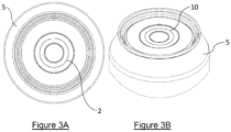
- the can end 1 When the can end 1 is seamed onto the can body 5 as shown in Figure 3 (using a conventional beverage can seaming process), the can end 1 closes an upper opening in the can body 5 (seaming of the end occurs after filling of the can body with a product).
- the can 8 is a two-piece can in which a bottom of the can body 5 is formed integrally with the can sidewalls (of course, use of a two-part can body is possible).
- the contents of the can 8 may be a beverage, a foodstuff, a household cleaning product, or a condiment; however this list is not exhaustive and other products, such as creams, ointments, healthcare and personal care products, and medical products, may be stored in the can 8.
- dry granular products may also be stored in the can 8.
- the can end 1 and the can body 5 are formed of steel, aluminium, or an aluminium alloy, and the filled can is pressurised to at least 10psi (68.9 kPa). Pressurising the can 8 is helpful in maintaining structural integrity for thin walled cans.
- FIG. 4 shows an exploded view of the dispenser 13 in which the can 8 of Figure 3 is loaded into a main body or "cup" 14, with a lid 15 and a dispensing cap 16 positioned for attachment to the cup 14, whilst Figure 5 shows a cross-sectional view of the exploded view of Figure 4 .
- Both the lid 15 and the cup 14 have cooperating features that allow the lid 15 to be removably secured to the cup 14.
- the cooperating features are threads 17 that allow the lid 15 and the cup 14 to be screwed together to completely enclose the can 8.
- a circular band 18 of an elastomeric plastic or other suitable material is located around the outside of the cup 14 such that it is “sandwiched" between the lid 15 and the cup 14 following closure, for example, to provide for a leak proof closure whilst preventing or limiting over-tightening.
- a corresponding circumferential region of the cup may be enlarged to provide a flush outer surface when the lid is attached.
- the threads 17 are formed on regions of the lid 15 and the cup 14 having reduced thicknesses such that the closed dispenser 13 has a substantially flush outer surface. It will be appreciated that the inner diameter of the cup 14 (and lid 15) are such as to allow the can to be easily inserted and removed.
- cup 14 provides additional support to the can 8 once it has been opened and potentially depressurised.
- the cup 14 and lid 15 may be made of metal, plastic or any other suitable material, as may other components of the dispenser.
- the lid 15 has a piercing member 19 that is configured to fracture the score 2 of the can end 1 upon closure, and thereby create an opening which brings the interior of the can 8 into communication with an interior space of the lid 15.
- the piercing member 19 acts as a device which gives mechanical advantage during closure, enabling the score 2 to be fractured during closure.
- the piercing member 19 has the form of a hollow cylindrical member that is concentric with the outer surface of the lid 15.
- the piercing member 19 has an axial length that varies around its circumference providing a tip 20.
- the outer diameter of the hollow cylindrical member 19 is very slightly less than the inner diameter of the score 2.
- the lid 15 comprises a resilient sealing member 21 in the form of an O-ring or the like, and which is located around the outer circumference of the piercing member 19, supported beneath a collar 22 extending circumferentially around the outer surface of the piercing member 19.
- Figures 7A and 7B show a pump-style dispensing cap 16 comprising a tube 23, a pump head 24, and a pumping mechanism (not shown but including, for example, a spring), located with respect to the cup 14 and loaded can 8.
- the dispensing cap 16 can be removably secured to the lid 15 (cf. Figure 7A and 7B ).
- a channel is defined through which a product can flow from the interior space of the can 8 to an exterior of the dispenser 13.
- the dispensing cap 16 also comprises a resilient sealing member 25 that forms a seal between the dispensing cap 16 and the lid 15 (see below).
- the resilient sealing member 25 may be in the form of a flattened elastomeric ring, an O-ring, or other suitable resilient member.
- the dispensing cap 16 does not of course need to be a pump-type dispenser and may be some other type of dispenser or valve as discussed below.
- a user loads a can (filled with product) into the dispenser cup 14.
- the lid 15 is located on the open end of the cup 14, above the tab-less can end.
- the user then presses the lid 15 onto the cup 14, with the threads 17 aligned, and rotates the lid 15 relative to the cup 14 to screw the lid 15 down onto the cup 14.
- This action provides the mechanical advantage that causes the tip 20 of the piercing member (the hollow cylinder) 19 to exert a force on a point just inside the score 2, causing the score to fracture at this point.
- the fracture will propagate around the score 2, whilst pushing the panel region within the score 2 into the can body 5.
- the fracture stops at the hinge 10 of course.
- the hinge 10 prevents the portion of the can end 1 that is outlined by the score 2 from fully separating from the can end 1. Upon completion of this operation, the resilient sealing member 21 surrounding the piercing member 19 is pressed into the opening, or around the panel region surrounding the formed opening, thereby establishing a seal between the interior of the can 8 and an interior space of the lid 15.
- this construction and method of operation allows the end 1 to be opened without the use of a tab.
- the can end 1 can be manufactured with fewer steps and with reduced metal.
- the underside of the can end 1 does not use or expose an adhesive, undesirable material interactions and product contamination are avoided.
- a still further advantage is that the cans 8 may be more effectively child-proofed, given that the cans 8 can only be opened with a suitable dispenser 13 which provides the needed mechanical advantage (or lid in the case where a container body is not required).
- the absence of a tab or ring pull means that the can 8 is not similar in appearance to a standard beverage can, and so is less likely to be mistaken for a can containing a typical single serve consumable product or indeed non-consumable product.
- the dispensing cap 16 is secured to the lid 15 by inserting the tube 23 through the interior space of the lid 15 until the resilient sealing member 25 is engaged beneath a circular shoulder extending around an upstanding cylindrical collar 22 of the lid 15. This is best illustrated by the detail of Figure 8B .
- the formed seal prevents the contents of the can 8 from leaking into the lid 15.
- the seal is also required of course to allow the dispensing cap 16 to pressurise the interior of the can 8 during operation of the pump, thereby causing the product to be forced up into the tube 23 and out through an exit port of the dispensing cap.
- Figures 9A and 9B show details of the various embodiments with different seal arrangements.
- the resilient sealing member 21 of the lid 15 provides a seal around or adjacent to the opening formed in the can end 1 by the fracturing of the score 2.
- the resilient sealing member 21 of the lid 15 presses against the portion of the can end 1 surrounding the score 2 to form the seal.
- the outer diameter of the sealing member 21 is marginally less than the diameter of the outer step 12a such that on closure the resilient sealing member 21 presses not only downwards onto the panel 7 but also radially against the step.
- the embodiment of Figure 9B is similar to that of Figure 9A , except that in the former the wall of the piercing member above the shoulder supporting the resilient sealing member is circularly cylindrical whilst in the latter that wall has a tapering thickness, increasing as it approaches the shoulder.
- the embodiment of Figure 9B may demonstrate increased strength and rigidity, especially during closure of the lid 15 onto the cup 14.
- lid 15 By configuring the lid 15 to form a suitable seal around the top of the can 8 it is possible to do away with the need for the dispenser 13 to have a cup 14 to support the can 8.
- Such an arrangement is shown in Figure 10 and comprises a lid 15 secured directly to the can 8.
- a snap-fit mechanism may be provided, whereby the user locates the lid 15 around the upper surface of the can 8, and presses down onto the lid 15 to cause features of the lid 15 to snap over and beneath the rim extending around the can end 1. This action also forces the piercing member 19 downwards, fracturing the score 2.
- the size of the can 8 may be different from that of a standard (330ml) beverage can to allow storage of different amounts of product.
- the can body may be "necked" to allow for use with a standard sized can end 1.
- a larger can 8 is advantageous over standard large storage containers such as glass bottles because the weight of the large can 8 will be less than the corresponding glass bottle. While terracing has been used in the present description to increase the strength of the can end 1, beading could also be used to increase the strength of the can end 1.
- radial beads could be used either in addition to the terracing, or instead of the terracing, on the can end 1.
- Using radial beading in addition to terracing could allow for larger can ends 1 to be manufactured that are still strong enough to withstand internal and external pressure.
- Reference numeral Feature 1 Can end 2. Score 3. Chuck wall 4. Curl 5. Can body 6. U-shaped channel 7. Central panel 8. Can 9. Circular path 10. Hinge 11. Terraces 12. a & b Steps 13. Dispenser 14. Main body/cup 15. Lid 16. Dispensing cap 17. Threads 18. Band 19.
- Piercing member 20 tip 21.
- Resilient sealing member (dispensing cap) 26. Pouring spout 27. Drinks optics 28. Push pull cap 29. Internal cylindrical collar
Landscapes
- Engineering & Computer Science (AREA)
- Mechanical Engineering (AREA)
- Containers Opened By Tearing Frangible Portions (AREA)
- Rigid Containers With Two Or More Constituent Elements (AREA)
- Closures For Containers (AREA)
Description
- The present invention relates can ends, metal cans and apparatus for dispensing therefrom. More particularly, the invention relates to tab-less can ends with scored features that can be opened by means of a dispenser.
- Currently, many products including household products such as detergents and personal care products are supplied in disposable plastic containers. It is widely recognised that such use of plastic containers is undesirable not least because of the environmental damage that arises from the disposal of such containers. Metal containers can provide a more environmentally friendly alternative and of course many products are already supplied in metal containers including foodstuffs, aerosols, mousses and the like. Such metal containers are often made using a relatively thick steel or aluminium which, whilst allowing for recycling, can be wasteful in terms of the materials used. They are also relatively expensive to manufacture and have higher manufacturing and transportation costs and therefore larger carbon "footprints", discouraging their use as a replacement for plastic containers.
-
WO2021/138708 describes a product dispensing system that makes use of what are substantially aluminium beverage cans. The can ends are either openable with tabs, e.g. in the form of a substantially fully open ends, or are provided with circular apertures closed with foil panels. The cans are filled with product and, for use, are loaded into a plastic two-part container comprising a main, generally cylindrical body and an end dispenser. In the case of an end with a tab, the end is opened by pulling the tab, and the can loaded into the body with the end dispenser being screwed over the can and onto the main body. The end dispenser is of a pump type and comprises a tube which is inserted through the opening in the can end. Once the end dispenser is secured to the main body, product can be dispensed. In the case where the can end has a foil panel, securing the end dispenser to the main body may cause the tube to break through the foil panel and pass into the can body. - Conventional beverage can production is highly optimised in terms of material use and manufacturing speed and cost. The use of a tab in the concept described in
WO2021/138708 is undesirable as it will increase metal usage, complexity and therefore cost. Whilst the use of a foil panel instead of a tab may address this problem, it will in turn introduce potential problems due to the departure from conventional end manufacturing processes. Furthermore, this approach will likely require the use of an adhesive, e.g. on the underside of the can end, potentially causing product contamination and / or product deterioration, as well as providing a weak point in the can end, e.g. the foil panel may be susceptible to breaking during transport as well as due to internal and external pressures. -
WO2012/136677 discloses a self-dispensing container for carbonated product and comprising a hollow body having a filling aperture, a carbonated product inserted into the hollow body via the filling aperture leaving a headspace, and an end adapted to seal the filling aperture after insertion of the carbonated product. After sealing, the headspace fills with CO2 from the carbonated product to equalise the pressure within the container. -
WO2016/170883 discloses a can having a tab-less end. A score extends around a region of the end such that a user can press down on the region within the score, fracturing the score and creating an opening in the end. -
JP2002179063 -
WO2013/172783 discloses a small capacity, full aperture beverage can and a can end for the same. -
WO2017/151419 discloses a resealable container lid assembly, including a cap rotationally assembled to a lid. - The invention is set out in the appended set of claims.
-
-
Figure 1A shows a plan view of a can end with a score; -
Figure 1B shows a top perspective view of the can end ofFigure 1A ; -
Figure 1C shows a bottom perspective view of the can end ofFigure 1A ; -
Figure 2 shows a cross sectional view of the can end ofFigure 1A taken along the line A-A, with enlarged call out; -
Figure 3A shows a top perspective view of a can comprising the can end ofFigure 1A seamed to a can body; -
Figure 3B shows a top perspective view of an upper region of the can ofFigure 3A ; -
Figure 4 shows an exploded view of a dispenser holding the can ofFigure 3 ; -
Figure 5 shows the dispenser and can ofFigure 4 in cross section; -
Figures 6A, 6B ,7A and 7B illustrate steps involved in closing the dispenser about the can; -
Figure 8A shows an enlarged cross sectional view of the can end and a piercing member of the dispenser lid before the dispensing cap has been secured to the lid; -
Figure 8B shows the enlarged cross sectional view ofFigure 8A after the dispensing cap has been secured to the lid; -
Figures 9A and 9B illustrate alternative means for providing a seal between the lid and the can end; -
Figure 10 shows an alternative dispenser in which the can ofFigure 3 is attached to a lid, and the seal is formed between the lid and the rim of the can end; -
Figures 11 to 13 illustrate alternative dispensing caps for the dispenser ofFigure 4 ; -
Figures 14A and 14B illustrate an alternative dispensing cap for a can; and -
Figure 15 illustrates a still further alternative dispensing cap for the dispenser ofFigure 4 . - A tab-less can end 1 will now be described with reference to
Figures 1A to 1C and2 . The can end is similar to standard beverage can ends, and the manufacturing process is also similar. For the purpose of the following discussion, theend 1 is assumed to be a "202" end having a seamed diameter of approximately 52mm. Of course other end sizes are possible (e.g. "200", "113", "206") and the skilled person will take account of this when determining dimensions of other end features. - The key differences between the
end 1 described here and standard ends are the absence of a tab and its associated score, and the provision of adiscontinuous score 2. Theend 1 is referred to here as a "tab-less end" due to the absence of the tab which is otherwise commonly used in the opening of a can end by pulling or pressing against its associated score, and is created by cutting out circular disks from metal sheet having a thickness in the range of 0.193 - 0.224mm. The disks are then formed to provide achuck wall 3 with acurl 4 at the top to allow seaming of theend 1 onto acan body 5. Thechuck wall 3 andcurl 4 extend around the entire circumference of theend 1, defining a generallyU-shaped channel 6 between thechuck wall 3 and acentral panel 7. Thescore 2 is formed on an upper surface of the panel 7 (i.e. on a surface that is exterior to thecan 8 after seaming of theend 1 to a can body 5), and follows a circular path 9 that is substantially concentric with thechuck wall 3. The diameter of thescore 2 is approximately 19mm, and has a depth of between 0.083 and 0.097mm, preferably approximately 0.09mm. For the metal thickness considered here, this results in a score "residual" of 0.07mm ± 0.03mm. - As the
score 2 is discontinuous, a portion of the circular path 9 is unscored. The unscored portion of the circular path 9 acts as ahinge 10 when the canend 1 is opened as discussed further below. The linear extent, indicated inFigure 1A by distance d, of thehinge 10 is preferably between 1 and 4mm, more preferably between 2 and 3mm, and more preferably substantially 3mm. The score depth (and therefore score residual) may be adjusted to optimise end performance. In particular, the score depth is deep enough that it can be opened with the aid of some device which gives mechanical advantage, but not so deep that it can be opened with a thumb or a finger pressing directly against it. - As best illustrated in
Figure 2 , thepanel 7 of thecan end 1 is formed to provide threeterraces 11 formed by two circular andconcentric steps first step 12a has a radius that is substantially 3.5mm greater than the radius of thescore 2, whilst thesecond step 12b has a radius that is substantially 3.2mm less than the radius of thescore 2. Theterraces 11 therefore descend in height towards the centre of theend 1, with thefirst step 12a having a step height of 0.43 mm and thesecond step 12b having a step height of 0.3mm. As is known in the art, the use of such terraces can "absorb" metal displaced during forming operations and can improve end performance by adding strength to the can end 1, minimising "doming" when the can end 1 is seamed onto acan body 5 and pressurised. - When the can end 1 is seamed onto the
can body 5 as shown inFigure 3 (using a conventional beverage can seaming process), the can end 1 closes an upper opening in the can body 5 (seaming of the end occurs after filling of the can body with a product). For the purpose of this discussion it is assumed that thecan 8 is a two-piece can in which a bottom of thecan body 5 is formed integrally with the can sidewalls (of course, use of a two-part can body is possible). The contents of thecan 8 may be a beverage, a foodstuff, a household cleaning product, or a condiment; however this list is not exhaustive and other products, such as creams, ointments, healthcare and personal care products, and medical products, may be stored in thecan 8. Additionally, dry granular products may also be stored in thecan 8. Preferably, the can end 1 and thecan body 5 are formed of steel, aluminium, or an aluminium alloy, and the filled can is pressurised to at least 10psi (68.9 kPa). Pressurising thecan 8 is helpful in maintaining structural integrity for thin walled cans. - A
dispenser 13 for use with thecan 8 ofFigure 3 will now be discussed with reference toFigures 4 to 6 .Figure 4 shows an exploded view of thedispenser 13 in which thecan 8 ofFigure 3 is loaded into a main body or "cup" 14, with alid 15 and a dispensingcap 16 positioned for attachment to thecup 14, whilstFigure 5 shows a cross-sectional view of the exploded view ofFigure 4 . Both thelid 15 and thecup 14 have cooperating features that allow thelid 15 to be removably secured to thecup 14. In this particular embodiment, the cooperating features arethreads 17 that allow thelid 15 and thecup 14 to be screwed together to completely enclose thecan 8. Optionally, acircular band 18 of an elastomeric plastic or other suitable material is located around the outside of thecup 14 such that it is "sandwiched" between thelid 15 and thecup 14 following closure, for example, to provide for a leak proof closure whilst preventing or limiting over-tightening. Alternatively, a corresponding circumferential region of the cup may be enlarged to provide a flush outer surface when the lid is attached. Thethreads 17 are formed on regions of thelid 15 and thecup 14 having reduced thicknesses such that theclosed dispenser 13 has a substantially flush outer surface. It will be appreciated that the inner diameter of the cup 14 (and lid 15) are such as to allow the can to be easily inserted and removed. This may require a small space to be present between the outer surface of the can and thecup 14, e.g. on the order of 1mm. When thecan 8 ofFigure 3 is loaded into thedispenser 13, thecup 14 provides additional support to thecan 8 once it has been opened and potentially depressurised. Thecup 14 andlid 15 may be made of metal, plastic or any other suitable material, as may other components of the dispenser. - As is perhaps best illustrated in the cross-sectional views of
Figures 6A (at initiation of closure of the lid 15) and 6B (during closure of the lid 15), thelid 15 has a piercingmember 19 that is configured to fracture thescore 2 of the can end 1 upon closure, and thereby create an opening which brings the interior of thecan 8 into communication with an interior space of thelid 15. The piercingmember 19 acts as a device which gives mechanical advantage during closure, enabling thescore 2 to be fractured during closure. The piercingmember 19 has the form of a hollow cylindrical member that is concentric with the outer surface of thelid 15. The piercingmember 19 has an axial length that varies around its circumference providing atip 20. To allow effective fracturing of thescore 2 upon closure, the outer diameter of the hollowcylindrical member 19 is very slightly less than the inner diameter of thescore 2. As will be discussed further below, thelid 15 comprises a resilient sealingmember 21 in the form of an O-ring or the like, and which is located around the outer circumference of the piercingmember 19, supported beneath acollar 22 extending circumferentially around the outer surface of the piercingmember 19. -
Figures 7A and 7B show a pump-style dispensing cap 16 comprising atube 23, apump head 24, and a pumping mechanism (not shown but including, for example, a spring), located with respect to thecup 14 and loaded can 8. The dispensingcap 16 can be removably secured to the lid 15 (cf.Figure 7A and 7B ). When the dispensingcap 16 is secured to thelid 15, e.g. via a snap-fit arrangement, a channel is defined through which a product can flow from the interior space of thecan 8 to an exterior of thedispenser 13. The dispensingcap 16 also comprises a resilient sealingmember 25 that forms a seal between the dispensingcap 16 and the lid 15 (see below). The resilient sealingmember 25 may be in the form of a flattened elastomeric ring, an O-ring, or other suitable resilient member. The dispensingcap 16 does not of course need to be a pump-type dispenser and may be some other type of dispenser or valve as discussed below. - The operation of assembling the
dispenser 13 around acan 8 will now be described. Reference to the cross-sectional detail ofFigure 8A will be helpful in this regard. - A user loads a can (filled with product) into the
dispenser cup 14. Thelid 15 is located on the open end of thecup 14, above the tab-less can end. The user then presses thelid 15 onto thecup 14, with thethreads 17 aligned, and rotates thelid 15 relative to thecup 14 to screw thelid 15 down onto thecup 14. This action provides the mechanical advantage that causes thetip 20 of the piercing member (the hollow cylinder) 19 to exert a force on a point just inside thescore 2, causing the score to fracture at this point. As the user continues to screw thelid 15 down, the fracture will propagate around thescore 2, whilst pushing the panel region within thescore 2 into thecan body 5. The fracture stops at thehinge 10 of course. Thehinge 10 prevents the portion of the can end 1 that is outlined by thescore 2 from fully separating from the can end 1. Upon completion of this operation, the resilient sealingmember 21 surrounding the piercingmember 19 is pressed into the opening, or around the panel region surrounding the formed opening, thereby establishing a seal between the interior of thecan 8 and an interior space of thelid 15. - It will be appreciated that this construction and method of operation allows the
end 1 to be opened without the use of a tab. The can end 1 can be manufactured with fewer steps and with reduced metal. Furthermore, because the underside of the can end 1 does not use or expose an adhesive, undesirable material interactions and product contamination are avoided. A still further advantage is that thecans 8 may be more effectively child-proofed, given that thecans 8 can only be opened with asuitable dispenser 13 which provides the needed mechanical advantage (or lid in the case where a container body is not required). Of course, the absence of a tab or ring pull means that thecan 8 is not similar in appearance to a standard beverage can, and so is less likely to be mistaken for a can containing a typical single serve consumable product or indeed non-consumable product. - After the
lid 15 has been secured to thecup 14 as described, the dispensingcap 16 is secured to thelid 15 by inserting thetube 23 through the interior space of thelid 15 until the resilient sealingmember 25 is engaged beneath a circular shoulder extending around an upstandingcylindrical collar 22 of thelid 15. This is best illustrated by the detail ofFigure 8B . The formed seal prevents the contents of thecan 8 from leaking into thelid 15. The seal is also required of course to allow the dispensingcap 16 to pressurise the interior of thecan 8 during operation of the pump, thereby causing the product to be forced up into thetube 23 and out through an exit port of the dispensing cap. -
Figures 9A and 9B show details of the various embodiments with different seal arrangements. In the embodiments ofFigure 9A , the resilient sealingmember 21 of thelid 15 provides a seal around or adjacent to the opening formed in the can end 1 by the fracturing of thescore 2. In the embodiment ofFigure 9A , the resilient sealingmember 21 of thelid 15 presses against the portion of the can end 1 surrounding thescore 2 to form the seal. The outer diameter of the sealingmember 21 is marginally less than the diameter of theouter step 12a such that on closure the resilient sealingmember 21 presses not only downwards onto thepanel 7 but also radially against the step. - The embodiment of
Figure 9B is similar to that ofFigure 9A , except that in the former the wall of the piercing member above the shoulder supporting the resilient sealing member is circularly cylindrical whilst in the latter that wall has a tapering thickness, increasing as it approaches the shoulder. The embodiment ofFigure 9B may demonstrate increased strength and rigidity, especially during closure of thelid 15 onto thecup 14. - It will be appreciated that by configuring the
lid 15 to form a suitable seal around the top of thecan 8 it is possible to do away with the need for thedispenser 13 to have acup 14 to support thecan 8. Such an arrangement is shown inFigure 10 and comprises alid 15 secured directly to thecan 8. In order to provide the force necessary for the piercingmember 19 to fracture thescore 2 and open the can end 1, a snap-fit mechanism may be provided, whereby the user locates thelid 15 around the upper surface of thecan 8, and presses down onto thelid 15 to cause features of thelid 15 to snap over and beneath the rim extending around the can end 1. This action also forces the piercingmember 19 downwards, fracturing thescore 2. - Reference is made to
Figures 11 to 14 which illustrate further configurations and uses of the dispenser 13: -
Figure 11 : The pump-type dispenser cap 16 described above is replaced by a pouringspout 26 which may be formed integrally with thelid 15. This is suitable, for example, for dispensing alcoholic beverages such as spirits, non-alcoholic cordial concentrates, or syrups or sauces. Thecup 14 of thedispenser 13 may be of a transparent plastic material allowing branding printed on thecan body 5 to be visible through thecup 14. -
Figure 12 : This arrangement is similar to that ofFigure 11 and is suitable for pouring liquids such as oil, as well as dry products such as sugar and coffee beans. An attractive design is created by manufacturing thedispenser 13 using a metal such as steel or aluminium, or with a chrome coated plastics. -
Figure 13 : The pump-type dispenser 13 is replaced with an "optics"connector 27 suitable for dispensing, for example, a spirit, non-alcoholic cordial concentrates, or syrups or sauces. Again, by forming thedispenser cup 14 from a transparent plastic material, branding printed on thecan body 5 is visible in use. -
Figures 14A and 14B : The pump-type dispenser cap 16 described above is replaced by apush pull cap 28 which may be formed integrally with thelid 15. Such acap 28 is suitable, for example, for direct consumption of the contents of thecan 8, such as water or another beverage. Alternatively, the contents of thecan 8 may still be poured from thepush pull cap 28 when it is in an open position. Thelid 15 may have an internalcylindrical collar 29 with an O-ring around the inner circumference such that when thelid 15 is pressed in place over a can end, a seal is formed between the collar and thecurl 4 of the can end 1. The seal keeps the contents of thecan 8 within the cylindrical volume created between thecollar 29 and the curl of the can end 1. -
Figure 15 illustrates a further embodiment with a similar lid to that of the embodiment ofFigures 14A and 14B . However, the lid is configured to be attached to adispenser cup 14 of the type previously described, e.g. by means of cooperating screw threads. - It will be appreciated by the person of skill in the art that various modifications may be made to the above described embodiments without departing from the scope of the present invention. For example, the size of the
can 8 may be different from that of a standard (330ml) beverage can to allow storage of different amounts of product. For a larger can size, the can body may be "necked" to allow for use with a standard sized can end 1. Alarger can 8 is advantageous over standard large storage containers such as glass bottles because the weight of thelarge can 8 will be less than the corresponding glass bottle. While terracing has been used in the present description to increase the strength of the can end 1, beading could also be used to increase the strength of the can end 1. For example, radial beads could be used either in addition to the terracing, or instead of the terracing, on the can end 1. Using radial beading in addition to terracing could allow for larger can ends 1 to be manufactured that are still strong enough to withstand internal and external pressure. - In understanding the above embodiments, reference should be made to the following table which identifies reference numerals and features of the drawings.
Reference numeral Feature 1. Can end 2. Score 3. Chuck wall 4. Curl 5. Can body 6. U-shaped channel 7. Central panel 8. Can 9. Circular path 10. Hinge 11. Terraces 12. a & b Steps 13. Dispenser 14. Main body/ cup 15. Lid 16. Dispensing cap 17. Threads 18. Band 19. Piercing member 20. tip 21. Resilient sealing member (piercing member) 22. Collar 23. Tube 24. Pump head 25. Resilient sealing member (dispensing cap) 26. Pouring spout 27. Drinks optics 28. Push pull cap 29. Internal cylindrical collar
Claims (10)
- A system for dispensing a product and comprising a can (8) having a can body (5) containing said product and a tab-less metal can end (1) seamed onto the can body (5), and a dispenser (13), wherein the can end (1) comprises:a substantially circular and planar panel (7);a chuck wall (3) extending around the periphery of the panel (7) and defining a curl (4); anda discontinuous score (2) formed in said panel and following a circular path (9) substantially concentric with said chuck wall (3), the score (2) defining a hinge (10) between first and second ends of the score (2),the discontinuous score (2) being such that it can be fractured by a user only when the user makes use of a mechanical advantage,the planar panel (7) defining an outer surface and an inner surface when the end (1) is seamed to the can body (5), and the panel (7) having a thickness in the range 0.193 - 0.224mm, said discontinuous score (2) being formed in the outer surface of the panel (7) and resulting in a score residual of 0.07mm ± 0.03mm, andwherein the dispenser (13) comprises:
a lid (15) having features for removably securing the lid (15) with respect to the can (8), and the lid (15) comprising a piercing member (19) configured to fracture the score (2) provided in the can end (1) and create an opening therethrough and thereby bring the interior of the can (8) into communication with an interior space of the lid (15). - The system according to claim 1, said features of the dispenser (13) comprising sealing features for removably securing the lid (15) directly to the can (8).
- The system according to claim 2, said sealing features providing a substantially fluid tight seal between the lid (15) and an outer surface or surfaces of the can (8).
- The system according to claim 1, the dispenser (13) comprising a main body (14) for receiving the can (8), the main body (14) comprising features for cooperating with said features of the lid (15) to fix the lid (15) to the main body (14), about a can (8).
- The system according to claim 4, said cooperating features of the lid (15) and the main body (14) comprising cooperating screw threads (17).
- The system according to claim 1 to 5, said piercing member (19) being provided by a hollow cylindrical member which defines said interior space, the cylindrical member having a variable axial length such that it provides a tip (20) for fracturing said score.
- The system according to claim 6, the dispenser comprising a resilient sealing member (21) extending around said cylindrical member to form a seal around or adjacent to the opening formed in the can end by the fracturing of the score (2).
- The system according to claim 6 or 7, the dispenser (13) comprising a dispensing cap (16) removably secured to said lid (15) and defining a channel through which a product can flow from an interior space of the can (8) to an exterior of the dispenser (13).
- The system according to claim 8, said dispensing cap (16) comprising a tube (23) for insertion through the opening in the can end (1), said tube (23) defining said channel.
- The system according to claim 8 or 9, said dispensing cap (16) comprising a resilient sealing member (25) configured to form a seal between the dispensing cap (16) and the lid (15).
Priority Applications (1)
| Application Number | Priority Date | Filing Date | Title |
|---|---|---|---|
| EP25161392.3A EP4537942A3 (en) | 2022-01-27 | 2023-01-06 | Dispenser with a lid and a sealing member |
Applications Claiming Priority (2)
| Application Number | Priority Date | Filing Date | Title |
|---|---|---|---|
| GB2201054.0A GB2615098A (en) | 2022-01-27 | 2022-01-27 | Can ends, metal cans and apparatus for dispensing therefrom |
| PCT/GB2023/050021 WO2023144504A1 (en) | 2022-01-27 | 2023-01-06 | Can ends, metal cans and apparatus for dispensing therefrom |
Related Child Applications (2)
| Application Number | Title | Priority Date | Filing Date |
|---|---|---|---|
| EP25161392.3A Division-Into EP4537942A3 (en) | 2022-01-27 | 2023-01-06 | Dispenser with a lid and a sealing member |
| EP25161392.3A Division EP4537942A3 (en) | 2022-01-27 | 2023-01-06 | Dispenser with a lid and a sealing member |
Publications (2)
| Publication Number | Publication Date |
|---|---|
| EP4469365A1 EP4469365A1 (en) | 2024-12-04 |
| EP4469365B1 true EP4469365B1 (en) | 2025-06-04 |
Family
ID=80621198
Family Applications (2)
| Application Number | Title | Priority Date | Filing Date |
|---|---|---|---|
| EP25161392.3A Pending EP4537942A3 (en) | 2022-01-27 | 2023-01-06 | Dispenser with a lid and a sealing member |
| EP23700150.8A Active EP4469365B1 (en) | 2022-01-27 | 2023-01-06 | Can ends, metal cans and apparatus for dispensing therefrom |
Family Applications Before (1)
| Application Number | Title | Priority Date | Filing Date |
|---|---|---|---|
| EP25161392.3A Pending EP4537942A3 (en) | 2022-01-27 | 2023-01-06 | Dispenser with a lid and a sealing member |
Country Status (7)
| Country | Link |
|---|---|
| US (1) | US20250128864A1 (en) |
| EP (2) | EP4537942A3 (en) |
| ES (1) | ES3034414T3 (en) |
| GB (1) | GB2615098A (en) |
| HU (1) | HUE072552T2 (en) |
| PL (1) | PL4469365T3 (en) |
| WO (1) | WO2023144504A1 (en) |
Families Citing this family (2)
| Publication number | Priority date | Publication date | Assignee | Title |
|---|---|---|---|---|
| US20250108392A1 (en) * | 2022-01-24 | 2025-04-03 | Dune Sciences, Inc. | Reusable canister system for dispensing fluid |
| US11772111B1 (en) * | 2022-09-16 | 2023-10-03 | Branded AcquiCo No 5, LLC | Dispenser |
Family Cites Families (13)
| Publication number | Priority date | Publication date | Assignee | Title |
|---|---|---|---|---|
| GB2240330A (en) * | 1990-01-25 | 1991-07-31 | Smiley Chien | Vessel for use with dispensing pump |
| US5680952A (en) * | 1994-09-12 | 1997-10-28 | Ball Corporation | End constructions for containers |
| US5642838A (en) * | 1995-12-28 | 1997-07-01 | Stoody; William Robert | Frangible sealing lid for spile access |
| JP3853433B2 (en) * | 1996-07-17 | 2006-12-06 | 大日本印刷株式会社 | Cartridge type liquid dispensing container |
| JP4578620B2 (en) * | 2000-05-18 | 2010-11-10 | 大和製罐株式会社 | Method for manufacturing easy-to-open can lid and easy-to-open can lid |
| JP4480881B2 (en) * | 2000-12-08 | 2010-06-16 | 大和製罐株式会社 | Easy-to-open can lid |
| EP2508447A1 (en) | 2011-04-08 | 2012-10-10 | Crown Packaging Technology, Inc. | Self-dispensing container |
| SG195407A1 (en) * | 2012-05-17 | 2013-12-30 | Crown Packaging Technology Inc | Beverage can and can end for same |
| JP6527380B2 (en) * | 2015-04-23 | 2019-06-05 | 昭和アルミニウム缶株式会社 | Can lid and can |
| WO2017151419A1 (en) * | 2016-02-29 | 2017-09-08 | Powercan Holding, Llc | Resealable container lid and accessories including methods of manufacture and use |
| DE102016106636A1 (en) * | 2016-04-11 | 2017-10-12 | Megaplast Gmbh | Dispenser for dispensing a liquid or pasty mass as well as a storage chamber designed as an exchange storage chamber |
| JP7316633B2 (en) * | 2019-03-20 | 2023-07-28 | 四国化工機株式会社 | Liquid filled container with dispensing pump |
| AU2020104293A4 (en) * | 2020-01-07 | 2021-03-11 | Circulr Research Pty Ltd | Vessel and system for reducing plastic waste |
-
2022
- 2022-01-27 GB GB2201054.0A patent/GB2615098A/en active Pending
-
2023
- 2023-01-06 WO PCT/GB2023/050021 patent/WO2023144504A1/en not_active Ceased
- 2023-01-06 US US18/730,682 patent/US20250128864A1/en active Pending
- 2023-01-06 EP EP25161392.3A patent/EP4537942A3/en active Pending
- 2023-01-06 EP EP23700150.8A patent/EP4469365B1/en active Active
- 2023-01-06 PL PL23700150.8T patent/PL4469365T3/en unknown
- 2023-01-06 ES ES23700150T patent/ES3034414T3/en active Active
- 2023-01-06 HU HUE23700150A patent/HUE072552T2/en unknown
Also Published As
| Publication number | Publication date |
|---|---|
| WO2023144504A1 (en) | 2023-08-03 |
| HUE072552T2 (en) | 2025-11-28 |
| US20250128864A1 (en) | 2025-04-24 |
| EP4469365A1 (en) | 2024-12-04 |
| EP4537942A2 (en) | 2025-04-16 |
| EP4537942A3 (en) | 2025-06-18 |
| GB202201054D0 (en) | 2022-03-16 |
| ES3034414T3 (en) | 2025-08-18 |
| GB2615098A (en) | 2023-08-02 |
| PL4469365T3 (en) | 2025-09-22 |
Similar Documents
| Publication | Publication Date | Title |
|---|---|---|
| US10968010B1 (en) | Resealable container lid and accessories including methods of manufacture and use | |
| KR102905294B1 (en) | Resealable container lids and accessories, including methods of manufacture and use | |
| US9272819B1 (en) | Resealable container lid including methods of manufacture and use | |
| EP2418155B1 (en) | Metal bottle can | |
| EP4469365B1 (en) | Can ends, metal cans and apparatus for dispensing therefrom | |
| US7918363B2 (en) | Resealable beverage container | |
| US9637269B1 (en) | Resealable container lid and accessories including methods of manufacturing and use | |
| EP2888172B1 (en) | Easy pour spout | |
| US20090272747A1 (en) | Multi-compartment fluid storage device | |
| US11021357B2 (en) | System and method for dispensing a beverage | |
| US11952164B1 (en) | Resealable container lid and accessories including methods of manufacture and use | |
| JP2024535391A (en) | Threaded container components with frustum-shaped surfaces to allow nesting | |
| EP3318623A1 (en) | Pressure relief valve assembly for containers for fluids, and container provided with such valve assembly | |
| AU2002325453B2 (en) | Container and method for manufacturing thereof | |
| CN218229765U (en) | Combined metal can | |
| US12365511B1 (en) | Sealing cap having tamper evidence ring for sealing resealable container and method of use | |
| AU2002325453A1 (en) | Container and method for manufacturing thereof | |
| NL2000169C2 (en) | Food container, in particular a beverage can, and method for manufacturing such a food container. | |
| KR200253222Y1 (en) | Can | |
| CN118317906A (en) | Threaded container component having a nestable frustum-shaped surface | |
| HK1258247B (en) | Resealable container lid assembly |
Legal Events
| Date | Code | Title | Description |
|---|---|---|---|
| STAA | Information on the status of an ep patent application or granted ep patent |
Free format text: STATUS: UNKNOWN |
|
| STAA | Information on the status of an ep patent application or granted ep patent |
Free format text: STATUS: THE INTERNATIONAL PUBLICATION HAS BEEN MADE |
|
| PUAI | Public reference made under article 153(3) epc to a published international application that has entered the european phase |
Free format text: ORIGINAL CODE: 0009012 |
|
| STAA | Information on the status of an ep patent application or granted ep patent |
Free format text: STATUS: REQUEST FOR EXAMINATION WAS MADE |
|
| 17P | Request for examination filed |
Effective date: 20240624 |
|
| AK | Designated contracting states |
Kind code of ref document: A1 Designated state(s): AL AT BE BG CH CY CZ DE DK EE ES FI FR GB GR HR HU IE IS IT LI LT LU LV MC ME MK MT NL NO PL PT RO RS SE SI SK SM TR |
|
| GRAP | Despatch of communication of intention to grant a patent |
Free format text: ORIGINAL CODE: EPIDOSNIGR1 |
|
| STAA | Information on the status of an ep patent application or granted ep patent |
Free format text: STATUS: GRANT OF PATENT IS INTENDED |
|
| DAV | Request for validation of the european patent (deleted) | ||
| DAX | Request for extension of the european patent (deleted) | ||
| INTG | Intention to grant announced |
Effective date: 20250107 |
|
| GRAS | Grant fee paid |
Free format text: ORIGINAL CODE: EPIDOSNIGR3 |
|
| GRAA | (expected) grant |
Free format text: ORIGINAL CODE: 0009210 |
|
| STAA | Information on the status of an ep patent application or granted ep patent |
Free format text: STATUS: THE PATENT HAS BEEN GRANTED |
|
| AK | Designated contracting states |
Kind code of ref document: B1 Designated state(s): AL AT BE BG CH CY CZ DE DK EE ES FI FR GB GR HR HU IE IS IT LI LT LU LV MC ME MK MT NL NO PL PT RO RS SE SI SK SM TR |
|
| REG | Reference to a national code |
Ref country code: GB Ref legal event code: FG4D |
|
| REG | Reference to a national code |
Ref country code: CH Ref legal event code: EP |
|
| REG | Reference to a national code |
Ref country code: DE Ref legal event code: R096 Ref document number: 602023003860 Country of ref document: DE |
|
| REG | Reference to a national code |
Ref country code: IE Ref legal event code: FG4D |
|
| REG | Reference to a national code |
Ref country code: ES Ref legal event code: FG2A Ref document number: 3034414 Country of ref document: ES Kind code of ref document: T3 Effective date: 20250818 |
|
| REG | Reference to a national code |
Ref country code: GR Ref legal event code: EP Ref document number: 20250401446 Country of ref document: GR Effective date: 20250808 |
|
| REG | Reference to a national code |
Ref country code: NL Ref legal event code: MP Effective date: 20250604 |
|
| PG25 | Lapsed in a contracting state [announced via postgrant information from national office to epo] |
Ref country code: FI Free format text: LAPSE BECAUSE OF FAILURE TO SUBMIT A TRANSLATION OF THE DESCRIPTION OR TO PAY THE FEE WITHIN THE PRESCRIBED TIME-LIMIT Effective date: 20250604 |
|
| REG | Reference to a national code |
Ref country code: LT Ref legal event code: MG9D |
|
| PG25 | Lapsed in a contracting state [announced via postgrant information from national office to epo] |
Ref country code: NO Free format text: LAPSE BECAUSE OF FAILURE TO SUBMIT A TRANSLATION OF THE DESCRIPTION OR TO PAY THE FEE WITHIN THE PRESCRIBED TIME-LIMIT Effective date: 20250904 |
|
| PG25 | Lapsed in a contracting state [announced via postgrant information from national office to epo] |
Ref country code: BG Free format text: LAPSE BECAUSE OF FAILURE TO SUBMIT A TRANSLATION OF THE DESCRIPTION OR TO PAY THE FEE WITHIN THE PRESCRIBED TIME-LIMIT Effective date: 20250604 |
|
| PG25 | Lapsed in a contracting state [announced via postgrant information from national office to epo] |
Ref country code: HR Free format text: LAPSE BECAUSE OF FAILURE TO SUBMIT A TRANSLATION OF THE DESCRIPTION OR TO PAY THE FEE WITHIN THE PRESCRIBED TIME-LIMIT Effective date: 20250604 |
|
| PG25 | Lapsed in a contracting state [announced via postgrant information from national office to epo] |
Ref country code: RS Free format text: LAPSE BECAUSE OF FAILURE TO SUBMIT A TRANSLATION OF THE DESCRIPTION OR TO PAY THE FEE WITHIN THE PRESCRIBED TIME-LIMIT Effective date: 20250904 |
|
| PG25 | Lapsed in a contracting state [announced via postgrant information from national office to epo] |
Ref country code: LV Free format text: LAPSE BECAUSE OF FAILURE TO SUBMIT A TRANSLATION OF THE DESCRIPTION OR TO PAY THE FEE WITHIN THE PRESCRIBED TIME-LIMIT Effective date: 20250604 |
|
| PG25 | Lapsed in a contracting state [announced via postgrant information from national office to epo] |
Ref country code: NL Free format text: LAPSE BECAUSE OF FAILURE TO SUBMIT A TRANSLATION OF THE DESCRIPTION OR TO PAY THE FEE WITHIN THE PRESCRIBED TIME-LIMIT Effective date: 20250604 |
|
| REG | Reference to a national code |
Ref country code: HU Ref legal event code: AG4A Ref document number: E072552 Country of ref document: HU |
|
| PG25 | Lapsed in a contracting state [announced via postgrant information from national office to epo] |
Ref country code: PT Free format text: LAPSE BECAUSE OF FAILURE TO SUBMIT A TRANSLATION OF THE DESCRIPTION OR TO PAY THE FEE WITHIN THE PRESCRIBED TIME-LIMIT Effective date: 20251006 |
|
| REG | Reference to a national code |
Ref country code: AT Ref legal event code: MK05 Ref document number: 1800172 Country of ref document: AT Kind code of ref document: T Effective date: 20250604 |
|
| PG25 | Lapsed in a contracting state [announced via postgrant information from national office to epo] |
Ref country code: IS Free format text: LAPSE BECAUSE OF FAILURE TO SUBMIT A TRANSLATION OF THE DESCRIPTION OR TO PAY THE FEE WITHIN THE PRESCRIBED TIME-LIMIT Effective date: 20251004 |
|
| PG25 | Lapsed in a contracting state [announced via postgrant information from national office to epo] |
Ref country code: SM Free format text: LAPSE BECAUSE OF FAILURE TO SUBMIT A TRANSLATION OF THE DESCRIPTION OR TO PAY THE FEE WITHIN THE PRESCRIBED TIME-LIMIT Effective date: 20250604 Ref country code: AT Free format text: LAPSE BECAUSE OF FAILURE TO SUBMIT A TRANSLATION OF THE DESCRIPTION OR TO PAY THE FEE WITHIN THE PRESCRIBED TIME-LIMIT Effective date: 20250604 |
|
| PG25 | Lapsed in a contracting state [announced via postgrant information from national office to epo] |
Ref country code: CZ Free format text: LAPSE BECAUSE OF FAILURE TO SUBMIT A TRANSLATION OF THE DESCRIPTION OR TO PAY THE FEE WITHIN THE PRESCRIBED TIME-LIMIT Effective date: 20250604 |
|
| PGFP | Annual fee paid to national office [announced via postgrant information from national office to epo] |
Ref country code: PL Payment date: 20251229 Year of fee payment: 4 |
|
| PG25 | Lapsed in a contracting state [announced via postgrant information from national office to epo] |
Ref country code: EE Free format text: LAPSE BECAUSE OF FAILURE TO SUBMIT A TRANSLATION OF THE DESCRIPTION OR TO PAY THE FEE WITHIN THE PRESCRIBED TIME-LIMIT Effective date: 20250604 |
|
| PG25 | Lapsed in a contracting state [announced via postgrant information from national office to epo] |
Ref country code: SK Free format text: LAPSE BECAUSE OF FAILURE TO SUBMIT A TRANSLATION OF THE DESCRIPTION OR TO PAY THE FEE WITHIN THE PRESCRIBED TIME-LIMIT Effective date: 20250604 |