EP4469343B1 - Automatische bootfestmachungsvorrichtung - Google Patents
Automatische bootfestmachungsvorrichtung Download PDFInfo
- Publication number
- EP4469343B1 EP4469343B1 EP23717655.7A EP23717655A EP4469343B1 EP 4469343 B1 EP4469343 B1 EP 4469343B1 EP 23717655 A EP23717655 A EP 23717655A EP 4469343 B1 EP4469343 B1 EP 4469343B1
- Authority
- EP
- European Patent Office
- Prior art keywords
- hands
- hook
- boat
- connector
- fixed
- Prior art date
- Legal status (The legal status is an assumption and is not a legal conclusion. Google has not performed a legal analysis and makes no representation as to the accuracy of the status listed.)
- Active
Links
Images








Classifications
-
- B—PERFORMING OPERATIONS; TRANSPORTING
- B63—SHIPS OR OTHER WATERBORNE VESSELS; RELATED EQUIPMENT
- B63B—SHIPS OR OTHER WATERBORNE VESSELS; EQUIPMENT FOR SHIPPING
- B63B21/00—Tying-up; Shifting, towing, or pushing equipment; Anchoring
-
- B—PERFORMING OPERATIONS; TRANSPORTING
- B63—SHIPS OR OTHER WATERBORNE VESSELS; RELATED EQUIPMENT
- B63B—SHIPS OR OTHER WATERBORNE VESSELS; EQUIPMENT FOR SHIPPING
- B63B21/00—Tying-up; Shifting, towing, or pushing equipment; Anchoring
- B63B2021/001—Mooring bars, yokes, or the like, e.g. comprising articulations on both ends
-
- B—PERFORMING OPERATIONS; TRANSPORTING
- B63—SHIPS OR OTHER WATERBORNE VESSELS; RELATED EQUIPMENT
- B63B—SHIPS OR OTHER WATERBORNE VESSELS; EQUIPMENT FOR SHIPPING
- B63B21/00—Tying-up; Shifting, towing, or pushing equipment; Anchoring
- B63B2021/003—Mooring or anchoring equipment, not otherwise provided for
- B63B2021/005—Resilient passive elements to be placed in line with mooring or towing chains, or line connections, e.g. dampers or springs
Definitions
- the invention in a broader sense belongs to the field of Nautics, and specifically relates to the mooring of boats to the port as well as to fixed and floating surfaces. (IPC B63B21/00;)
- This device is only used for parallel mooring in the front part of the ship, the "bow of the boat", in a safe and efficient way, so that while parking we automatically moor to the device which is fixed on the dock.
- this device is designed to be used with two different connectors, so that users of the device, depending on the model of the vessel, have the opportunity to choose the necessary connector as the best option for mooring their boat.
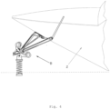
- the device can be used for mooring all standard boats that have a front part with a steep and sharp bow, [ Fig.2 ].
- This device has two legs (3), four arms (4), two connector bridges (9), two heads (6), two floaters (1), the connector (A and B) and hooks (5 and 7).
- the head (6) has square profiles above and below it (54) for mounting the connectors (A and B).
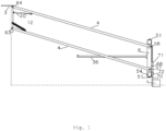
- the legs (3) are made to be fixed with screws (55) to the dock which on the front vertical side has a lower axis (63) and an upper axis (64) to connect the hands (4), [ Fig.1 ], which connect with a bridge (9).
- Two identical hands (4) stay parallel and are connected with a bridge (9) near the legs (3), [ Fig.7 ].
- the connector (A) we fix the hands (4) with the bridge (9) so that they extend away from the head (6), [ Fig.7 ].
- the connector (B) we fix the hands in the opposite direction, so that they approach the head (6), [ Fig.8 ].
- the hooks (5 and 7) are formed from stainless steel plates tightened at the beginning and widened at the bottom in the shape of a triangle, where in the outer part, widened in the form of an arc, they have an open hook (67) with a mechanism for closing the hook, which is fixed in the inner part of the hooks (5).
- the hook mechanism (5), [ Fig.14 ], consists of a safeguard (46) which is attached to a shaft (50) where there is a spring (47) to hold the safeguard in the closed position and a lever (49) with which we push the safeguard to release it from the device.
- the hook (7) [ Fig.15 ] has a mechanism similar to the hook (5), except that instead of the lever (49) there is a cable (48), which is mounted on the upper part of the bow of the boat in order to, by pulling the cable, release the safeguard and disconnect the boat from the device.
- the connector (A), figures 2 and 3 is part of the device to which the boat is automatically connected by using the hooks (5).
- the connector (A) consists of two identical mechanisms which are connected by a cable.
- the shock absorbers (10) have the same two-sided resistance and eliminate uncontrolled oscillations of the device during waves, making it more stable, [ Fig.1 ].
- the cables (22) serve as guides and help to guide and moor to the device.
- the connector (B), [ Fig.6 ], is designed for connection to the boat, at the beginning of the bow on the lower front of the boat where the hook (17), is usually location [ Fig.12 ] .
- the hook (7) is dedicated to the automatic connection to the connector (B) and in the lower part there is a closed hook (13), which replaces the old hook (17) of the bow of the boat.
- the hook (7) for mounting on the boat has a hole for the screw (18), a cutout for the second screw (19) so that the screw can be furthered away and brought closer to fit the same holes where the hook was (17 ) and at the tip of the hook, a hole for the third screw (20 ).
- the holder (15) of the connector (B) is inserted into the square profiles (54) on the left and right head (6), figure (5 ).
- the spiral spring (28) is fixed in a vertical position with the lower holder (56) with screws (65).
- the upper holder (16) is fixed, which is connected to the shaft (62) with the seat (38), which can move up and down on the shaft and be fixed in the right position depending on the angle of the front of the boat.
- the seat has four wheels (39) on which the boat rests, two arms (40) that are attached to the seat with screws (53).
- the arms (40) are spread out in the shape of the letter V, at the beginning they each have one joint (52), in the middle there is a joint (41) to be tuned according to the boat and they serve to steer the boat straight to the device (B).
- the float (1) can be mounted on the opposite side, on its box (71), especially when it comes to a low boat, and it is necessary to lower the connector (B) to level it with the hook (7), [ Fig.5 ].
- the connector device (B) is leveled by adjusting the float (1) so that the height of the rod (29) is level with the top of the hook (7), picture 9.
- a toothed safeguard (31) is fixed on the toothed rod (30) that limits its movement in one direction only, so that the boat moving towards the device, [ Fig.9 ], with the hook (7) is connected to the rod (29) picture 4, and pushes the triangular mechanism forward until the boat is completely fixed with the seat (38), picture 5.
- the tension spring (75) serves to keep the mechanism in a position ready for mooring which is fixed to the seat (38) and the end of the rod (30).
- the safeguard (31) keeps the boat tight on the seat.
- This safeguard on the upper side has a ring (32) to which the cable (33) is attached and serves to pull the safeguard from the toothed rod (30).
- a gear (44) is fixed with which we can manually move the mechanism and tighten the boat on the seat if necessary, [ Fig.6 ].
- the spring (28) Since the spring (28) is fixed up and down so as not to rotate, the spring keeps the rear of the boat in check by allowing minimal left and right movement and keeps the boat in a parallel position.
- the suitable dimensions of the spring (28) are: height 40 cm, length 11 cm and thickness 12 mm.
- Older methods of mooring boats mainly using buoys, anchors and ropes are most frequently used, which means that new research have not brought an effective solution.
- the essence is that every previous method of mooring boats has its shortcomings, and the result is a large number of damaged vessels at the docks.
- the most frequently used method of mooring boats is with buoys that serve to prevent the moored boat from coming into direct contact with the dock. Buoys often do not help under the influence of weather conditions such as winds, waves, and fluctuating water levels.
- Another commonly used method is to use the anchor on the opposite side, to keep the boat away from the dock, but it is not an adequate solution because occasionally the anchor loosens, which causes the boat to come into direct contact with the surface where it is moored.
- patent 5,361,716 shows a device having a spring fixed to the base on one side and fixed to the handle attached to the boat on the other side by bending the spring at an angle of 90 o or semicircular depending on the water level, which means that the spring must be so weak that we can bend it in a semicircle with one hand to tie it to the boat with the other, and the movement of the middle boat under the influence of the wave can have as much as 20 times more force than that spring and will not be bothered by it while impacting the port.
- the published application US2938492A shows the device that uses the spring that is installed on the vessel, on the top of which the telescopic tube is fastened and attached to the dock.
- CN 112 942 252 A shows a ship berthing device comprising a bidirectional controlling mechanism used for continuously pulling a ship to the pier side when the ship is subjected to offshore wind and avoiding surface damage of the ship.
- the device is provided with two pairs of parallel hands, with the lower ends of the hands attached to a horizontally movable support in the pier, and the upper ends of hands attached to a horizontal positioning rod which is attached to the ship.
- the essence of the invention is a new device for the mooring of boats to docks, whose connectors ensure the necessary height of the boat even when it is not moored, so that when the boat approaches the device it is automatically moored efficiently and safely.
- the device monitors and controls the movements of the moored boat during waves and winds, tides, ebbs, and when the water level falls and rises.
- the device is designed to secure the boat at the same time with several mechanisms that activate based on the strength of the boat's movement and allow the boat to rock in a controlled manner under the influence of smaller waves and control the movement of the boat under the influence of medium and strong waves, making the device efficient.
- this device When the weather conditions are good and there are no waves, this device with the connectors (A and B) always keep the boat moored in the same position, which means that less space is needed on the dock compared to other mooring methods.
- the device with connector (A) monitors and limits the movements of the boat with cables attached to the springs, while the connector (B) monitors and limits the movements of the boat with a spring in a flexible way, on which the boat is connected to the front part.
- the connector (A) When it comes to stronger waves, the connector (A) also has a pressure spring that is activated to soften the strong movements, while the connector (B) has a spring that moves flexibly and attractively to absorb the movements.
- the arms of the device are connected to the base of the shaft and equipped with shock absorbers so that they move up and down during the waves, tracking and limiting the movements of the moored boat.
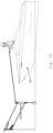
- [ Fig.1 ] shows the side view of the device.
- [ Fig.2 ] shows the frontal view of the boat moored to the device with the connector (A).
- [ Fig.3 ] shows in detail the connector (A) in the cross-section, outside of the device and connected to the device.
- [ Fig.4 ] shows the first stage of connecting the boat to the connector (B).
- [ Fig.5 ] shows the boat fully connected to the connector (B).
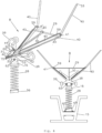
- [ Fig.6 ] shows the side and front view, detailing the connector (B).
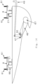
- [ Fig.7 ] shows a top view of the boat moored to the device with the connector (A).
- [ Fig.8 ] shows the device from above with the connector (B).
- [ Fig.9 ] shows the tuning of the device with the connector (B) and the boat.
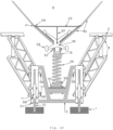
- [ Fig.10 ] shows the front view of the device with the connector (B).
- Fig 11 shows the hook (5) in the position when it is not in use.
- [ Fig.12 ] shows the boat moored to the device with the connector (A) when the water level lowers and rises.
- [ Fig.13 ] shows the boat and the device with the connector (A) during tuning and when we manually test the anchor for the first time.
- [ Fig.14 ] shows the hook (5) in detail.
- [ Fig.15 ] shows the hook (7) in detail.
Landscapes
- Chemical & Material Sciences (AREA)
- Engineering & Computer Science (AREA)
- Combustion & Propulsion (AREA)
- Mechanical Engineering (AREA)
- Ocean & Marine Engineering (AREA)
- Bridges Or Land Bridges (AREA)
- Toys (AREA)
- Underground Structures, Protecting, Testing And Restoring Foundations (AREA)
- Motorcycle And Bicycle Frame (AREA)
- Details Of Connecting Devices For Male And Female Coupling (AREA)
- Hooks, Suction Cups, And Attachment By Adhesive Means (AREA)
Claims (5)
- Vorrichtung zum Festmachen von Booten, die einen Verbinder (A; B) aufweist und ferner zwei erste Arme (4), die mit einer Brücke (9) verbunden sind und auf einer Seite horizontal mit zwei Schenkeln (3) auf ersten unteren Achsen (63) verbunden sind, und zwei zweite Arme (4), die mit den Schenkeln (3) auf ersten oberen Achsen (64) verbunden sind, aufweist, wobei jeder der ersten Arme (4) auf der anderen Seite vertikal mit einem entsprechenden der zweiten Arme (4) durch einen Kopf (6) über zweite untere Achsen (57) und zweite obere Achsen (58) verbunden sind, wobei die zweiten unteren Achsen (57) und zweiten oberen Achsen (58) dazwischen den gleichen Abstand haben wie die ersten unteren Achsen und ersten oberen Achsen; wobeidie Köpfe (6) aufweisen:an oberen und unteren Seiten quadratische Profile (54) zum Anbringen der Verbinder (A; B),Schrauben (51) zum Befestigen,einen Schwimmer (1) an einer Vorderseite des Kopfes (6) mit einem teleskopischen Halter (70), der durch sein Gehäuse (71) hindurchgeht, das am Kopf (6) mit Schrauben (68) befestigt ist, wobei die Vorrichtung fernerzwei Federn (12), die mit den Schenkeln (3) und den ersten Armen (4) verbunden sind, und zwei Dämpfer (10), die mit den Schenkeln (3) und den zweiten Armen (4) verbunden sind, aufweist.
- Vorrichtung nach Anspruch 1, wobei der Verbinder (A) eine Schraube (26) aufweist, die durch eine Abdeckung (69) auf einer Rückseite eines ersten quadratischen Gehäuses (27) hindurchgeht und in eine Mutter (65) eingeschraubt ist, die am Anfang einer Zugfeder (23) befestigt ist, wobei die Zugfeder auf der anderen Seite mit einem quadratischen Verbinder (45) verbunden ist, der ein Kabel (22) aufweist, das durch eine Druckfeder (24), durch eine Frontabdeckung (74) und durch ein Rad (25) hindurchgeht, das erste Gehäuse (27) mit einer Länge verlässt, die gleich dem Abstand zwischen den beiden Profilen (54) ist, und mit einem zweiten Gehäuse (27) verbunden ist, das den gleichen Mechanismus wie das erste aufweist.
- Vorrichtung nach Anspruch 1, wobei der Verbinder (B) eine Spiralfeder (28) aufweist, die an einer unteren Seite an einem Halter (15) und an einer oberen Seite an einer Stütze (16) befestigt ist, wobei die Stütze (16) an einer oberen Seite eine Achse (62) aufweist, mit der ein Sitz (38) verbunden ist, so dass er sich auf und ab bewegen und in der richtigen Position mit Schrauben befestigt werden kann, wobei der Sitz (38) an den jeweiligen Enden vier Räder (39) aufweist, in der Mitte ein Einschnitt (42) vorhanden ist, durch den eine Zahnstange (30) verläuft, wobei an einem vorderen Teil der Zahnstange (30) eine weitere Stange (29) angebracht ist, die die Form des Buchstabens T bildet und lateral mit weiteren Stangen (43) verstärkt ist, die mit einem Ende der Zahnstange (30) ein Dreieck bilden, wobei sich an einem hinteren Ende des Einschnitts (42) eine Zahnsicherung (31) befindet, die eine Bewegung der Zahnstange (30) nur in eine Richtung zulässt, und sich an einem vorderen Ende des Einschnitts (42) ein Zahnrad (44) befindet; wobei der Verbinder (B) ferner zwei Arme (40) aufweist, die mit Schrauben (53) lateral am Sitz (38) in der Form des Buchstabens V befestigt sind, wobei die beiden Arme (40) an einer Oberseite einen Begrenzer (59) aufweisen, am Anfang jeweils ein Gelenk (52) aufweisen und sich in der Mitte die Arme (40) jeweils mit einem Gelenk (41) erstrecken.
- Vorrichtung nach Anspruch 1 bis 3, die ferner Haken (5) aufweist, wobei jeder Haken eine Edelstahlplatte mit einer dreieckigen Form aufweist, die am Anfang spitz zuläuft und in einem verbreiterten unteren Teil einen bogenförmigen offenen Haken (67) aufweist, wobei in der Mitte ein innerer Einschnitt vorhanden ist und ein Mechanismus mit einer Sicherung (46) an einer Achse (50) befestigt ist, wobei der Mechanismus eine Feder (47) zum Halten der Sicherung (46) in einer geschlossenen Position und einen Hebel (49) zum Lösen der Sicherung (46) aufweist und wobei der Haken (5) ferner an einer Oberseite zwei Halter (8) aufweist, die durch gezahnte Scharniere (21) verbunden sind.
- Vorrichtung nach den Ansprüchen 1 bis 3, die ferner einen Haken (7) aufweist, wobei der Haken eine Edelstahlplatte in Form eines Dreiecks mit einem spitzen Anfang und einem verlängerten Ende in Form eines Bogens mit einem geschlossenen Haken (13) und vor dem verlängerten Ende an einer unteren Seite einen offenen Haken (67), einen inneren Ausschnitt in der Mitte und einen Mechanismus mit einer Sicherung (46) aufweist, der an einer Welle (50) befestigt ist, wobei der Mechanismus eine Feder (47) zum Halten der Sicherung (46) in einer geschlossenen Position und ein Kabel (48) zum Lösen der Sicherung (46) aufweist, wobei der Haken (7) ferner auf einer Oberseite ein erstes Loch für eine Schraube (18), ein zweites Loch für eine weitere Schraube (20) und einen Ausschnitt für eine Abstimmschraube (19) aufweist.
Priority Applications (1)
| Application Number | Priority Date | Filing Date | Title |
|---|---|---|---|
| HRP20250537TT HRP20250537T1 (hr) | 2023-03-27 | 2023-03-27 | Uređaj za automatski vez za čamac |
Applications Claiming Priority (1)
| Application Number | Priority Date | Filing Date | Title |
|---|---|---|---|
| PCT/IB2023/053009 WO2024201097A1 (en) | 2023-03-27 | 2023-03-27 | Automatic boat mooring device |
Publications (4)
| Publication Number | Publication Date |
|---|---|
| EP4469343A1 EP4469343A1 (de) | 2024-12-04 |
| EP4469343C0 EP4469343C0 (de) | 2025-04-30 |
| EP4469343B1 true EP4469343B1 (de) | 2025-04-30 |
| EP4469343B8 EP4469343B8 (de) | 2025-12-17 |
Family
ID=86052413
Family Applications (2)
| Application Number | Title | Priority Date | Filing Date |
|---|---|---|---|
| EP23717655.7A Active EP4469343B8 (de) | 2023-03-27 | 2023-03-27 | Automatische bootfestmachungsvorrichtung |
| EP24715751.4A Pending EP4688550A1 (de) | 2023-03-27 | 2024-03-26 | Automatische bootfestmachungsvorrichtung |
Family Applications After (1)
| Application Number | Title | Priority Date | Filing Date |
|---|---|---|---|
| EP24715751.4A Pending EP4688550A1 (de) | 2023-03-27 | 2024-03-26 | Automatische bootfestmachungsvorrichtung |
Country Status (5)
| Country | Link |
|---|---|
| EP (2) | EP4469343B8 (de) |
| AU (1) | AU2024244515A1 (de) |
| ES (1) | ES3028427T3 (de) |
| HR (1) | HRP20250537T1 (de) |
| WO (2) | WO2024201097A1 (de) |
Family Cites Families (8)
| Publication number | Priority date | Publication date | Assignee | Title |
|---|---|---|---|---|
| US2938492A (en) | 1959-08-10 | 1960-05-31 | Edward L Kulick | Mooring device |
| US3155069A (en) * | 1962-08-17 | 1964-11-03 | B P Tanker Company Ltd | Mooring arrangements for ships |
| US4250827A (en) | 1978-07-20 | 1981-02-17 | Booker William G | Boat mooring device |
| US4751892A (en) * | 1987-06-26 | 1988-06-21 | Daniel Sechel | Marine standoff |
| US5361716A (en) | 1993-10-18 | 1994-11-08 | Dock Tender, Inc. | Boat mooring device and method |
| WO2009058977A2 (en) * | 2007-11-01 | 2009-05-07 | Mark Ebbenga | Latch for boat bow |
| US11628910B1 (en) * | 2019-07-29 | 2023-04-18 | Dalian University Of Technology | String-type mooring system |
| CN112942252B (zh) * | 2021-03-26 | 2021-12-14 | 广东海洋大学 | 一种船艇靠泊装置及船舰靠泊方法 |
-
2023
- 2023-03-27 WO PCT/IB2023/053009 patent/WO2024201097A1/en not_active Ceased
- 2023-03-27 ES ES23717655T patent/ES3028427T3/es active Active
- 2023-03-27 EP EP23717655.7A patent/EP4469343B8/de active Active
- 2023-03-27 HR HRP20250537TT patent/HRP20250537T1/hr unknown
-
2024
- 2024-03-26 WO PCT/EP2024/058152 patent/WO2024200465A1/en not_active Ceased
- 2024-03-26 AU AU2024244515A patent/AU2024244515A1/en active Pending
- 2024-03-26 EP EP24715751.4A patent/EP4688550A1/de active Pending
Also Published As
| Publication number | Publication date |
|---|---|
| EP4469343A1 (de) | 2024-12-04 |
| EP4469343C0 (de) | 2025-04-30 |
| AU2024244515A1 (en) | 2025-11-13 |
| WO2024200465A1 (en) | 2024-10-03 |
| ES3028427T3 (en) | 2025-06-19 |
| WO2024201097A1 (en) | 2024-10-03 |
| HRP20250537T1 (hr) | 2025-06-20 |
| EP4688550A1 (de) | 2026-02-11 |
| EP4469343B8 (de) | 2025-12-17 |
Similar Documents
| Publication | Publication Date | Title |
|---|---|---|
| US8091499B1 (en) | Boat mooring device | |
| US6915753B1 (en) | Mooring apparatus | |
| JP4394453B2 (ja) | 海洋係留用浮船 | |
| US5361716A (en) | Boat mooring device and method | |
| US4031582A (en) | Floating structure | |
| US7827924B1 (en) | Boat mooring device | |
| US5937781A (en) | Floating piling attachment device with shock absorbing capability | |
| CN110435819B (zh) | 船舶固定系统及船舶固定方法 | |
| US7322308B2 (en) | Mooring apparatus with moveable ballast weight | |
| EP4469343B1 (de) | Automatische bootfestmachungsvorrichtung | |
| CN211256850U (zh) | 一种适应于海洋潮汐的浮动码头 | |
| US5716249A (en) | Mooring means | |
| US6490988B2 (en) | Anchor assembly for boats and watercrafts in general | |
| CN108360460B (zh) | 观光船登乘装置 | |
| CN214690085U (zh) | 一种可调节式船舶防撞设施 | |
| CN208455574U (zh) | 拉索式水下靠泊系统 | |
| US5944451A (en) | Dock compensator | |
| CN221608782U (zh) | 一种浮式系泊装置 | |
| HRUM20250053U2 (hr) | Uređaj za privez broda | |
| FI117195B (fi) | Menetelmä ja laitteisto aluksen kiinnittämiseksi rakenteeseen tai toiseen alukseen | |
| CN221345303U (zh) | 一种高水位落差浮桥锚固装置 | |
| US11648868B1 (en) | Vessel guidance system | |
| SU1736831A1 (ru) | Одноточечный рейдовый причал | |
| WO2025171463A1 (en) | Boat docking system and kit of parts therefor | |
| AU2013205360B2 (en) | Swing mooring pontoon |
Legal Events
| Date | Code | Title | Description |
|---|---|---|---|
| REG | Reference to a national code |
Ref country code: HR Ref legal event code: TUEP Ref document number: P20250537T Country of ref document: HR |
|
| STAA | Information on the status of an ep patent application or granted ep patent |
Free format text: STATUS: UNKNOWN |
|
| STAA | Information on the status of an ep patent application or granted ep patent |
Free format text: STATUS: THE INTERNATIONAL PUBLICATION HAS BEEN MADE |
|
| PUAI | Public reference made under article 153(3) epc to a published international application that has entered the european phase |
Free format text: ORIGINAL CODE: 0009012 |
|
| STAA | Information on the status of an ep patent application or granted ep patent |
Free format text: STATUS: REQUEST FOR EXAMINATION WAS MADE |
|
| GRAP | Despatch of communication of intention to grant a patent |
Free format text: ORIGINAL CODE: EPIDOSNIGR1 |
|
| STAA | Information on the status of an ep patent application or granted ep patent |
Free format text: STATUS: GRANT OF PATENT IS INTENDED |
|
| 17P | Request for examination filed |
Effective date: 20240311 |
|
| AK | Designated contracting states |
Kind code of ref document: A1 Designated state(s): AL AT BE BG CH CY CZ DE DK EE ES FI FR GB GR HR HU IE IS IT LI LT LU LV MC ME MK MT NL NO PL PT RO RS SE SI SK SM TR |
|
| INTG | Intention to grant announced |
Effective date: 20241125 |
|
| GRAS | Grant fee paid |
Free format text: ORIGINAL CODE: EPIDOSNIGR3 |
|
| GRAA | (expected) grant |
Free format text: ORIGINAL CODE: 0009210 |
|
| STAA | Information on the status of an ep patent application or granted ep patent |
Free format text: STATUS: THE PATENT HAS BEEN GRANTED |
|
| AK | Designated contracting states |
Kind code of ref document: B1 Designated state(s): AL AT BE BG CH CY CZ DE DK EE ES FI FR GB GR HR HU IE IS IT LI LT LU LV MC ME MK MT NL NO PL PT RO RS SE SI SK SM TR |
|
| DAV | Request for validation of the european patent (deleted) | ||
| DAX | Request for extension of the european patent (deleted) | ||
| REG | Reference to a national code |
Ref country code: CH Ref legal event code: EP Ref country code: GB Ref legal event code: FG4D |
|
| REG | Reference to a national code |
Ref country code: IE Ref legal event code: FG4D |
|
| REG | Reference to a national code |
Ref country code: DE Ref legal event code: R096 Ref document number: 602023003225 Country of ref document: DE |
|
| U01 | Request for unitary effect filed |
Effective date: 20250430 |
|
| U07 | Unitary effect registered |
Designated state(s): AT BE BG DE DK EE FI FR IT LT LU LV MT NL PT RO SE SI Effective date: 20250508 |
|
| REG | Reference to a national code |
Ref country code: ES Ref legal event code: FG2A Ref document number: 3028427 Country of ref document: ES Kind code of ref document: T3 Effective date: 20250619 |
|
| REG | Reference to a national code |
Ref country code: HR Ref legal event code: T1PR Ref document number: P20250537 Country of ref document: HR |
|
| REG | Reference to a national code |
Ref country code: GR Ref legal event code: EP Ref document number: 20250400956 Country of ref document: GR Effective date: 20250613 |
|
| PG25 | Lapsed in a contracting state [announced via postgrant information from national office to epo] |
Ref country code: NO Free format text: LAPSE BECAUSE OF FAILURE TO SUBMIT A TRANSLATION OF THE DESCRIPTION OR TO PAY THE FEE WITHIN THE PRESCRIBED TIME-LIMIT Effective date: 20250730 |
|
| PG25 | Lapsed in a contracting state [announced via postgrant information from national office to epo] |
Ref country code: PL Free format text: LAPSE BECAUSE OF FAILURE TO SUBMIT A TRANSLATION OF THE DESCRIPTION OR TO PAY THE FEE WITHIN THE PRESCRIBED TIME-LIMIT Effective date: 20250430 |
|
| PG25 | Lapsed in a contracting state [announced via postgrant information from national office to epo] |
Ref country code: RS Free format text: LAPSE BECAUSE OF FAILURE TO SUBMIT A TRANSLATION OF THE DESCRIPTION OR TO PAY THE FEE WITHIN THE PRESCRIBED TIME-LIMIT Effective date: 20250731 |
|
| PG25 | Lapsed in a contracting state [announced via postgrant information from national office to epo] |
Ref country code: IS Free format text: LAPSE BECAUSE OF FAILURE TO SUBMIT A TRANSLATION OF THE DESCRIPTION OR TO PAY THE FEE WITHIN THE PRESCRIBED TIME-LIMIT Effective date: 20250830 |
|
| GRAT | Correction requested after decision to grant or after decision to maintain patent in amended form |
Free format text: ORIGINAL CODE: EPIDOSNCDEC |
|
| REG | Reference to a national code |
Ref country code: CH Ref legal event code: Y10 Free format text: ST27 STATUS EVENT CODE: U-0-0-Y10-Y00 (AS PROVIDED BY THE NATIONAL OFFICE) Effective date: 20251112 |
|
| REG | Reference to a national code |
Ref country code: CH Ref legal event code: Q17 Free format text: ST27 STATUS EVENT CODE: U-0-0-Q10-Q17 (AS PROVIDED BY THE NATIONAL OFFICE) Effective date: 20251119 |
|
| RIN2 | Information on inventor provided after grant (corrected) |
Inventor name: VULJAJ, SOKOLJ |
|
| PG25 | Lapsed in a contracting state [announced via postgrant information from national office to epo] |
Ref country code: SM Free format text: LAPSE BECAUSE OF FAILURE TO SUBMIT A TRANSLATION OF THE DESCRIPTION OR TO PAY THE FEE WITHIN THE PRESCRIBED TIME-LIMIT Effective date: 20250430 |
|
| PG25 | Lapsed in a contracting state [announced via postgrant information from national office to epo] |
Ref country code: CZ Free format text: LAPSE BECAUSE OF FAILURE TO SUBMIT A TRANSLATION OF THE DESCRIPTION OR TO PAY THE FEE WITHIN THE PRESCRIBED TIME-LIMIT Effective date: 20250430 |
|
| PG25 | Lapsed in a contracting state [announced via postgrant information from national office to epo] |
Ref country code: SK Free format text: LAPSE BECAUSE OF FAILURE TO SUBMIT A TRANSLATION OF THE DESCRIPTION OR TO PAY THE FEE WITHIN THE PRESCRIBED TIME-LIMIT Effective date: 20250430 |
|
| PLBE | No opposition filed within time limit |
Free format text: ORIGINAL CODE: 0009261 |
|
| STAA | Information on the status of an ep patent application or granted ep patent |
Free format text: STATUS: NO OPPOSITION FILED WITHIN TIME LIMIT |
|
| REG | Reference to a national code |
Ref country code: CH Ref legal event code: L10 Free format text: ST27 STATUS EVENT CODE: U-0-0-L10-L00 (AS PROVIDED BY THE NATIONAL OFFICE) Effective date: 20260311 |
|
| REG | Reference to a national code |
Ref country code: CH Ref legal event code: U11 Free format text: ST27 STATUS EVENT CODE: U-0-0-U10-U11 (AS PROVIDED BY THE NATIONAL OFFICE) Effective date: 20260401 |
|
| PGFP | Annual fee paid to national office [announced via postgrant information from national office to epo] |
Ref country code: ME Payment date: 20260306 Year of fee payment: 4 |
|
| 26N | No opposition filed |
Effective date: 20260202 |
|
| REG | Reference to a national code |
Ref country code: HR Ref legal event code: ODRP Ref document number: P20250537 Country of ref document: HR Payment date: 20260309 Year of fee payment: 4 |
|
| PGFP | Annual fee paid to national office [announced via postgrant information from national office to epo] |
Ref country code: IE Payment date: 20260318 Year of fee payment: 4 |
|
| PGFP | Annual fee paid to national office [announced via postgrant information from national office to epo] |
Ref country code: HR Payment date: 20260309 Year of fee payment: 4 |
|
| PGFP | Annual fee paid to national office [announced via postgrant information from national office to epo] |
Ref country code: TR Payment date: 20260310 Year of fee payment: 4 |
|
| PGFP | Annual fee paid to national office [announced via postgrant information from national office to epo] |
Ref country code: GR Payment date: 20260320 Year of fee payment: 4 Ref country code: CY Payment date: 20260225 Year of fee payment: 4 |