EP4468786A1 - Pin-herstellungsverfahren und -vorrichtung - Google Patents
Pin-herstellungsverfahren und -vorrichtung Download PDFInfo
- Publication number
- EP4468786A1 EP4468786A1 EP23746431.8A EP23746431A EP4468786A1 EP 4468786 A1 EP4468786 A1 EP 4468786A1 EP 23746431 A EP23746431 A EP 23746431A EP 4468786 A1 EP4468786 A1 EP 4468786A1
- Authority
- EP
- European Patent Office
- Prior art keywords
- pin
- information
- user equipment
- registration
- pegc
- Prior art date
- Legal status (The legal status is an assumption and is not a legal conclusion. Google has not performed a legal analysis and makes no representation as to the accuracy of the status listed.)
- Pending
Links
Images


Classifications
-
- H—ELECTRICITY
- H04—ELECTRIC COMMUNICATION TECHNIQUE
- H04W—WIRELESS COMMUNICATION NETWORKS
- H04W12/00—Security arrangements; Authentication; Protecting privacy or anonymity
- H04W12/08—Access security
- H04W12/086—Access security using security domains
-
- H—ELECTRICITY
- H04—ELECTRIC COMMUNICATION TECHNIQUE
- H04L—TRANSMISSION OF DIGITAL INFORMATION, e.g. TELEGRAPHIC COMMUNICATION
- H04L67/00—Network arrangements or protocols for supporting network services or applications
- H04L67/01—Protocols
- H04L67/12—Protocols specially adapted for proprietary or special-purpose networking environments, e.g. medical networks, sensor networks, networks in vehicles or remote metering networks
-
- H—ELECTRICITY
- H04—ELECTRIC COMMUNICATION TECHNIQUE
- H04W—WIRELESS COMMUNICATION NETWORKS
- H04W12/00—Security arrangements; Authentication; Protecting privacy or anonymity
- H04W12/10—Integrity
- H04W12/108—Source integrity
-
- H—ELECTRICITY
- H04—ELECTRIC COMMUNICATION TECHNIQUE
- H04W—WIRELESS COMMUNICATION NETWORKS
- H04W12/00—Security arrangements; Authentication; Protecting privacy or anonymity
- H04W12/50—Secure pairing of devices
-
- H—ELECTRICITY
- H04—ELECTRIC COMMUNICATION TECHNIQUE
- H04W—WIRELESS COMMUNICATION NETWORKS
- H04W12/00—Security arrangements; Authentication; Protecting privacy or anonymity
- H04W12/60—Context-dependent security
- H04W12/69—Identity-dependent
-
- H—ELECTRICITY
- H04—ELECTRIC COMMUNICATION TECHNIQUE
- H04W—WIRELESS COMMUNICATION NETWORKS
- H04W4/00—Services specially adapted for wireless communication networks; Facilities therefor
- H04W4/70—Services for machine-to-machine communication [M2M] or machine type communication [MTC]
-
- H—ELECTRICITY
- H04—ELECTRIC COMMUNICATION TECHNIQUE
- H04W—WIRELESS COMMUNICATION NETWORKS
- H04W48/00—Access restriction; Network selection; Access point selection
- H04W48/08—Access restriction or access information delivery, e.g. discovery data delivery
-
- H—ELECTRICITY
- H04—ELECTRIC COMMUNICATION TECHNIQUE
- H04W—WIRELESS COMMUNICATION NETWORKS
- H04W48/00—Access restriction; Network selection; Access point selection
- H04W48/16—Discovering, processing access restriction or access information
-
- H—ELECTRICITY
- H04—ELECTRIC COMMUNICATION TECHNIQUE
- H04W—WIRELESS COMMUNICATION NETWORKS
- H04W84/00—Network topologies
- H04W84/02—Hierarchically pre-organised networks, e.g. paging networks, cellular networks, WLAN [Wireless Local Area Network] or WLL [Wireless Local Loop]
- H04W84/10—Small scale networks; Flat hierarchical networks
- H04W84/105—PBS [Private Base Station] network
-
- G—PHYSICS
- G16—INFORMATION AND COMMUNICATION TECHNOLOGY [ICT] SPECIALLY ADAPTED FOR SPECIFIC APPLICATION FIELDS
- G16Y—INFORMATION AND COMMUNICATION TECHNOLOGY SPECIALLY ADAPTED FOR THE INTERNET OF THINGS [IoT]
- G16Y30/00—IoT infrastructure
-
- H—ELECTRICITY
- H04—ELECTRIC COMMUNICATION TECHNIQUE
- H04W—WIRELESS COMMUNICATION NETWORKS
- H04W84/00—Network topologies
- H04W84/02—Hierarchically pre-organised networks, e.g. paging networks, cellular networks, WLAN [Wireless Local Area Network] or WLL [Wireless Local Loop]
- H04W84/10—Small scale networks; Flat hierarchical networks
Definitions
- This application pertains to the field of communication technologies, and specifically relates to a personal internet of things network (Personal IoT Network, PIN) creation method and a device.
- PIN Personal internet of things network
- wearable devices such as cameras, headsets, watches, headphones, and health monitors
- internet of things devices such as smart lights, cameras, thermostats, doors sensors, voice assistants, speakers, refrigerators, and washing machines
- PINs to realize interconnection, mutual communication, service acquisition and other services between devices.
- the related technology does not provide a relevant solution on how to create a PIN, and consequently makes it difficult to meet a requirement of communication between devices.
- Embodiments of this application provide a PIN creation method and a device, to resolve a problem that a requirement of communication between devices cannot be met because a PIN cannot be created in related technologies.
- a PIN creation method including: a user equipment sends networking request information to a PIN server.
- the networking request information is used to request to create a PIN.
- the user equipment receives networking response information from the PIN server.
- the networking response information includes creation success information or creation failure information, the creation success information indicates that the PIN is successfully created, and the creation failure information indicates that the PIN fails to be created.
- a PIN creation method including: a PIN server receives networking request information from a user equipment.
- the networking request information is used to request to create a PIN.
- the PIN server sends networking response information to the user equipment.
- the networking response information includes creation success information or creation failure information, the creation success information indicates that the PIN is successfully created, and the creation failure information indicates that the PIN fails to be created.
- a PIN creation method including: a user equipment establishes a communication connection to a PEMC through non-3GPP access.
- the user equipment sends first registration request information to the PEMC.
- the first registration request information is used to request to become a PEGC in a PIN.
- the user equipment receives first registration response information from the PEMC.
- the first registration response information includes registration success information or registration failure information, the registration success information indicates that the first registration request information has been verified, and the registration failure information indicates that the first registration request information fails to be verified.
- a PIN creation method including: a user equipment establishes a communication connection to a PEMC through non-3GPP access.
- the user equipment sends second registration request information to the PEMC.
- the second registration request information is used to request to become a PIN element in a PIN.
- the user equipment receives second registration response information from the PEMC.
- the second registration response information includes registration success information or registration failure information, the registration success information indicates that the second registration request information has been verified, and the registration failure information indicates that the second registration request information fails to be verified.
- a PIN creation apparatus including: a sending module, configured to send networking request information to a PIN server, where the networking request information is used to request to create a PIN; and a receiving module, configured to receive networking response information from the PIN server, where the networking response information includes creation success information or creation failure information, the creation success information indicates that the PIN is successfully created, and the creation failure information indicates that the PIN fails to be created.
- a PIN creation apparatus including: a receiving module, configured to receive networking request information from a user equipment, where the networking request information is used to request to create a PIN; and a sending module, configured to send networking response information to the user equipment, where the networking response information includes creation success information or creation failure information, the creation success information indicates that the PIN is successfully created, and the creation failure information indicates that the PIN fails to be created.
- a PIN creation apparatus including: a communication establishment module, configured to establish a communication connection to a PEMC through non-3GPP access; a sending module, configured to send first registration request information to the PEMC, where the first registration request information is used to request to become a PEGC in a PIN; and a receiving module, configured to receive first registration response information from the PEMC, where the first registration response information includes registration success information or registration failure information, the registration success information indicates that the first registration request information has been verified, and the registration failure information indicates that the first registration request information fails to be verified.
- a PIN creation apparatus including: a communication establishment module, configured to establish a communication connection to a PEMC through non-3GPP access; a sending module, configured to send second registration request information to the PEMC, where the second registration request information is used to request to become a PIN element in a PIN; and a receiving module, configured to receive second registration response information from the PEMC, where the second registration response information includes registration success information or registration failure information, the registration success information indicates that the second registration request information has been verified, and the registration failure information indicates that the second registration request information fails to be verified.
- a user equipment includes a processor and a memory, the memory stores a program or an instruction executable on the processor, and when the program or the instruction is executed by the processor, the steps of the method according to the first aspect, the third aspect, or the fourth aspect are implemented.
- a user equipment including a processor and a communication interface.
- the communication interface is configured to implement the steps of the method according to the first aspect, the third aspect, or the fourth aspect.
- a network side device includes a processor and a memory, the memory stores a program or an instruction executable on the processor, and when the program or the instruction is executed by the processor, the steps of the method according to the second aspect are implemented.
- a network side device including a processor and a communication interface.
- the communication interface is configured to implement the steps of the method according to the second aspect.
- a PIN creation system including a user equipment and a network side device.
- the user equipment may be configured to perform the steps of the method according to the first aspect, the third aspect, or the fourth aspect, and the network side device may be configured to perform the steps of the method according to the second aspect.
- a readable storage medium stores a program or an instruction, and when the program or the instruction is executed by a processor, the steps of the method according to the first aspect, the second aspect, the third aspect, or the fourth aspect are implemented.
- a chip includes a processor and a communication interface, the communication interface is coupled to the processor, and the processor is configured to run a program or an instruction to implement the steps of the method according to the first aspect, the second aspect, the third aspect, or the fourth aspect.
- a computer program/program product is provided.
- the computer program/program product is stored in a storage medium, and the program/program product is executed by at least one processor to implement the steps of the method according to the first aspect, the second aspect, the third aspect, or the fourth aspect.
- the user equipment sends the networking request information to the PIN server.
- the networking request information is used to request to create the PIN.
- the user equipment receives the networking response information.
- the networking response information includes the creation success information or the creation failure information. That is, after verifying the networking request information, the PIN server may agree or disagree to a networking request of the user equipment.
- Embodiments of this application enable the user equipment to create the PIN. This is conducive to meeting a requirement of communication between devices by using the PIN.
- first, second, and the like in this specification and claims of this application are used to distinguish between similar objects instead of describing a specific order or sequence. It should be understood that, the terms used in such a way is interchangeable in proper circumstances, so that embodiments of this application can be implemented in an order other than the order illustrated or described herein.
- Objects classified by “first” and “second” are usually of a same type, and the number of objects is not limited. For example, there may be one or more first objects.
- "and/or" represents at least one of connected objects, and a character “/” generally represents an "or” relationship between associated objects.
- technologies described in embodiments of this application are not limited to a long term evolution (Long Term Evolution, LTE)/LTE-advanced (LTE-Advanced, LTE-A) system, and may further be applied to other wireless communication systems such as code division multiple access (Code Division Multiple Access, CDMA), time division multiple access (Time Division Multiple Access, TDMA), frequency division multiple access (Frequency Division Multiple Access, FDMA), orthogonal frequency division multiple access (Orthogonal Frequency Division Multiple Access, OFDMA), single-carrier frequency division multiple access (Single-carrier Frequency Division Multiple Access, SC-FDMA), and other systems.
- code division multiple access Code Division Multiple Access
- TDMA time division multiple access
- FDMA frequency division multiple access
- OFDMA Orthogonal frequency division multiple access
- SC-FDMA single-carrier Frequency Division Multiple Access
- SC-FDMA single-carrier Frequency Division Multiple Access
- NR New Radio
- 6G 6th Generation
- FIG. 1 is a block diagram of a wireless communication system to which embodiments of this application may be applied.
- the wireless communication system includes a user equipment 11 and a network side device 12.
- the user equipment 11 may be a user equipment side device such as a mobile phone, a tablet personal computer (Tablet Personal Computer), a laptop computer (Laptop Computer) or a notebook computer, a personal digital assistant (Personal Digital Assistant, PDA), a palmtop computer, a netbook, an ultra-mobile personal computer (ultra-mobile personal computer, UMPC), a mobile internet device (Mobile Internet Device, MID), an augmented reality (augmented reality, AR)/virtual reality (virtual reality, VR) device, a robot, a wearable device (Wearable Device), vehicle user equipment (Vehicle User Equipment, VUE), pedestrian user equipment (Pedestrian User Equipment, PUE), smart household (household devices with wireless communication functions, such as a refrigerator, a television, a washing machine, or furniture), a game console, a personal
- the network side device 12 may include an access network device or a core network device.
- the access network device may also be referred to as a radio access network device, a radio access network (Radio Access Network, RAN), a radio access network function, or a radio access network unit.
- the access network device may include a base station a wireless local area network (Wireless Local Area Network, WLAN) access node, a wireless fidelity (Wireless Fidelity, Wi-Fi) node, or the like.
- the base station may be referred to as a NodeB, an evolved NodeB (eNB), an access point, a base transceiver station (Base Transceiver Station, BTS), a radio base station, a radio transceiver, a basic service set (Basic Service Set, BSS), an extended service set (Extended Service Set, ESS), a home NodeB, a home evolved NodeB, a transmitting receiving point (Transmitting Receiving Point, TRP), or another appropriate term in the art.
- the base station is not limited to a specified technical term.
- the core network device may include but is not limited to at least one of the following: a core network node, a core network function, a mobility management entity (Mobility Management Entity, MME), an access management function (Access Management Function, AMF), a session management function (Session Management Function, SMF), a user plane function (User Plane Function, UPF), a policy control function (Policy Control Function, PCF), a policy and charging rules function (Policy and Charging Rules Function, PCRF), an edge application server discovery function (Edge Application Server Discovery Function, EASDF), a unified data management (Unified Data Management, UDM), a unified data repository (Unified Data Repository, UDR), a home subscriber server (Home Subscriber Server, HSS), a centralized network configuration (Centralized network configuration, CNC), a network repository function (Network Re
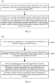
- an embodiment of this application provides a PIN creation method 200.
- the method may be performed by a user equipment.
- the method may be performed by software or hardware installed in the user equipment.
- the method includes the following steps.
- S202 The user equipment sends networking request information to a PIN server, where the networking request information is used to request to create a PIN.
- the user equipment receives networking response information from the PIN server, where the networking response information includes creation success information or creation failure information, the creation success information indicates that the PIN is successfully created, and the creation failure information indicates that the PIN fails to be created.
- the user equipment in this embodiment may be a personal internet of things network element with management capability (PIN element with management capability, PEMC).
- the user equipment may be an enabler (enabler) on the PEMC, such as an application (Application, APP) on the PEMC or an enabled client.
- the user equipment Before this embodiment is executed, the user equipment has subscribed to an operator to become a user of the operator; and has obtained an identity of the PEMC; and also obtained an internet protocol (Internet Protocol, IP) address of the PIN server.
- IP internet protocol
- a networking request can be triggered only after obtaining the identity of the PEMC.
- the method further includes the following steps:
- the user equipment sends a subscription request information to the PIN server, and the subscription request information is used to request at least one of the following: become a PEMC; register in or subscribe to an operator network; and the user equipment receives subscription success information from the PIN server.
- the subscription success information indicates that the user equipment becomes a PEMC, and a new PEMC identity (Identity, ID) can be assigned to the PEMC.
- the subscription failure means that the PEMC fails to perform registration and subscription, and does not obtain the role of PEMC.
- the PIN server should indicate the reason for this subscription failure.
- the subscription request information includes at least one of the following: (a) an application ID on the PEMC, where in a case that the user equipment is a PEMC, the application ID on the PEMC is an application ID on the user equipment; (b) a subscription permanent identifier (Subscription Permanent Identifier, SUPI) of the user equipment; (c) a generic public subscription identifier (Subscription Permanent Identifier, GPSI) of the user equipment; (d) an IP address of the user equipment; (e) an PEMC client IP address, where in a case that the user equipment is a PEMC, the PEMC client IP address is a client IP address of the user equipment; and (f) a security credential.
- embodiments of this application can also resolve the following technical problems. Because different internet of things devices are developed by different manufacturers, there are different access methods and different design structures. Currently, there is no a unified architecture and a unified process that allow devices from a plurality of manufacturers to create PINs. Embodiments of this application enable different internet of things devices to create PINs. This is conducive to meeting a requirement of communication between devices by using the PINs.
- the networking request information may include at least one of the following (1) to (6).
- the creation success information includes at least one of the following.
- the foregoing embodiments mainly introduce how the user equipment creates a PIN.
- the following will describe how the user equipment determines the PEGC in the PIN.
- the user equipment may add the PEGC to the PIN in the following methods.
- One method is that the PEGC has a direct connection to the PEMC, such as a wired direct connection or a wireless direct connection. In this way, after the PEGC and the PEMC communicate, the PEGC may interact with the PEMC. Therefore, the PEGC can be registered in the PEMC, and the PEMC can set the PEGC as a gateway of the PIN.
- Another method is that after the PEGC is started, the PEGC directly interacts with the PIN server to register in the PIN server, and then obtains a role of a gateway from the operator.
- the PIN server assigns the PEGC to the networking request or the PIN to become a gateway.
- the PEMC can obtain an IP address of the gateway, the PEMC and the PEGC establish a communication process, the PEGC can be registered in the PEMC, and both are on the same PIN.
- the user equipment determines the PEGC in the PIN by using at least one of the following methods.
- the method further includes the following steps. (1) The user equipment establishes a communication connection to the PEGC through non-3GPP access. For example, the communication connection is established through hotspot direct connection. (2) The user equipment receives first registration request information from the PEGC. (3) The user equipment verifies the first registration request information and sends first registration response information.
- the first registration response information includes registration success information or registration failure information, the registration success information indicates that the first registration request information has been verified, and the registration failure information indicates that the first registration request information fails to be verified. If the first registration request information fails to be verified, it means that PEGC fails to perform registration and subscription.
- the user equipment or PEMC should indicate the reason for this registration failure.
- the first registration request information includes at least one of the following: the ID of the PEGC, the enabler ID of the PEGC, the ID of the user equipment, the application ID on the PEGC, the IP address of the PEGC, the security credential, the access control information, and the routing information.
- the first registration response information includes at least one of the following: a registration ID, registration termination time information, and a context ID of the PEGC.
- the foregoing embodiments mainly introduce how the user equipment creates the PIN and how the user equipment determines the PEGC in the PIN.
- the following will introduce how the user equipment adds a PIN element to the PIN.
- the PIN When the PIN is successfully created, the PIN already includes the PEMC and the PEGC. At this time, another internet of things device may wish to join the PIN.
- One method is that the PEMC opens its own hotspot. In this case, the PIN element can access the hotspot and register in the PEMC. The PEMC can pull the device into a specific PIN to become a member.
- Another method is that the PIN element itself is a user equipment, then the PIN element can also open its own hotspot for the PEMC to access. After the PEMC interacts with the PIN element, because hotspots of PIN elements are different (for example, the SSID), then PEMC can distinguish different PIN elements, and finally, pull these PIN elements into the PIN to become members.
- the foregoing embodiments further includes the following step.
- the user equipment adds a PIN element to the PIN.
- That the user equipment adds a PIN element to the PIN includes: (1) The user equipment establishes a communication connection to the PIN element through non-3GPP access. For example, the communication connection is established through hotspot direct connection. (2) The user equipment receives second registration request information from the PIN element. (3) In a case that the second registration request has been verified, the user equipment adds the PIN element to the PIN. (4) The user equipment sends second registration response information.
- the second registration request information includes at least one of the following: the ID of the PIN element, the enabler ID of the PIN element, an application ID on the PIN element, the IP address of the PIN element, and the security credential.
- the second registration response information includes at least one of the following: the registration ID, the registration termination time information, the context ID of the PIN element, and the ID of the PIN. If the second registration request fails to be verified, the user equipment should give the reason for the registration failure.
- the method further includes: The user equipment determines permission of the PIN element.
- the permission includes, for example, whether 5G can be visited by using the PEGC, and whether another service server can be visited by using the 5G network.
- the second registration response information also includes at least one of the following.
- the access permission of the PIN element is obtained by the user equipment from the PIN server, or is determined by the user equipment based on PEGC registration information.
- the PIN element may access the target network by using the PEGC through the user name, the account number, the password, the service set identifier (Service Set Identifier, SSID), the basic service set identifier (Basic Service Set Identifier, BSSID), and the like issued by the PEMC.
- Service Set Identifier Service Set Identifier
- BSSID Basic Service Set Identifier
- the PIN creation method according to embodiments of this application is described above in detail with reference to FIG. 2 .
- a PIN creation method according to another embodiment of this application is described in detail below with reference to FIG. 3 . It can be understood that description from a PIN server side is the same as or corresponds to the description from the user equipment side in the method shown in FIG. 2 . To avoid repetition, relevant description is appropriately omitted.
- FIG. 3 is a schematic flowchart of implementing the PIN creation method according to this embodiment of this application. The method may be applied to the PIN server side. As shown in FIG. 3 , a method 300 includes the following steps.
- a PIN server receives networking request information from a user equipment, where the networking request information is used to request to create a PIN.
- the PIN server is configured to verify or agree to the PIN networking request.
- the PIN server sends networking response information to the user equipment, where the networking response information includes creation success information or creation failure information, the creation success information indicates that the PIN is successfully created, and the creation failure information indicates that the PIN fails to be created.
- the PIN server receives the networking request information.
- the networking request information is used to request to create the PIN.
- the PIN server sends the networking response information to the user equipment.
- the networking response information includes the creation success information or the creation failure information. That is, after verifying the networking request information, the PIN server may agree or disagree to a networking request of the user equipment.
- Embodiments of this application enable the user equipment to create the PIN. This is conducive to meeting a requirement of communication between devices by using the PIN.
- the creation failure information indicates that the networking request is not agreed to, and the PIN server may indicate the reason for this networking failure.
- the networking request information includes at least one of the following: (1) life cycle information of the PIN, where the life cycle information is used to indicate a time when the PIN takes effect or exists; (2) identifier information related to the user equipment; (3) an IP address or a port number of the user equipment; (4) information of a PIN element that the user equipment expects to add to the PIN; (5) information of a PEGC in the PIN; and (6) a security credential.
- the identifier information related to the user equipment includes at least one of the following: an ID of a PEMC in the PIN, an enabler ID of the user equipment, an SUPI of the user equipment, a GPSI, an application ID on the PEMC in the PIN, and an enabled client ID of the PEMC.
- the information of the PIN element includes at least one of the following: an ID of the PIN element, an enabler ID of the PIN element, a user equipment ID of the PIN element, the application ID on the PEMC in the PIN, an IP address of the PIN element, and an enabler IP address of the PIN element.
- the information of the PEGC includes at least one of the following: an ID of the PEGC, an enabler ID of the PEGC, a user equipment ID of the PEGC, an application ID on the PEGC, and an IP address of the PEGC.
- the creation success information includes at least one of the following: (1) an identifier ID of the PIN; (2) the information of the PEGC in the PIN; (3) access control information configured to the PEGC in the PIN, where the access control information is used to control whether the PIN element in the PIN can visit or access a target network; and (4) routing information configured to the PEGC in the PIN, where the routing information is used for the PEGC or the PIN element in the PIN to visit the target network.
- the access control information includes at least one of the following: a user name, an account number, a password, an SSID, and a BSSID; and/or the routing information includes at least one of the following: an IP address of a UPF, a port number of the UPF, an FQDN of the UPF, and a data network DN connected by using the UPF, where the PEGC visits the target network by accessing the UPF.
- the method further includes: The PIN server sends the information of the PEGC in the PIN to the user equipment.
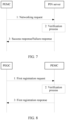
- FIG. 4 is a schematic flowchart of implementing a PIN creation method according to an embodiment of this application. The method may be applied to a user equipment such as a PEGC side. As shown in FIG. 4 , a method 400 includes the following steps.
- S402 The user equipment establishes a communication connection to a PEMC through non-3GPP access.
- S404 The user equipment sends first registration request information to the PEMC, where the first registration request information is used to request to become a PEGC in a PIN.
- the user equipment receives first registration response information from the PEMC, where the first registration response information includes registration success information or registration failure information, the registration success information indicates that the first registration request information has been verified, and the registration failure information indicates that the first registration request information fails to be verified.
- the verification failure means that a registration request is not agreed to, and the PEMC may indicate the reason for this registration failure.
- the user equipment can apply to become the PEGC in the PIN.
- the PEGC enables a PIN element in the PIN to visit a 5G network or visit another service server by using the 5G network. This is conducive to meeting a requirement of communication between devices by using the PIN.
- the first registration request information includes at least one of the following: an ID of the user equipment, an enabler ID of the user equipment, an application ID on the user equipment, an IP address of the user equipment, a security credential, access control information, and routing information; and/or the first registration response information includes at least one of the following: a registration ID, registration termination time information, and a context ID of the user equipment.
- FIG. 5 is a schematic flowchart of implementing a PIN creation method according to an embodiment of this application. The method may be applied to a user equipment such as a PIN element side. As shown in FIG. 5 , a method 500 includes the following steps.
- S502 The user equipment establishes a communication connection to a PEMC through non-3GPP access.
- S504 The user equipment sends second registration request information to the PEMC, where the second registration request information is used to request to become a PIN element in a PIN.
- the user equipment receives second registration response information from the PEMC, where the second registration response information includes registration success information or registration failure information, the registration success information indicates that the second registration request information has been verified, and the registration failure information indicates that the second registration request information fails to be verified.
- the verification failure means that a registration request has not been agreed to, and the PEMC may indicate the reason for this registration failure.
- the user equipment can apply to become the PIN element in the PIN.
- the PIN element can visit a 5G network by using the PEGC in the PIN or visit another service server by using the 5G network. This is conducive to meeting a communication requirement.
- the second registration request information includes at least one of the following: an ID of the user equipment, an enabler ID of the user equipment, an application ID on the user equipment, an IP address of the user equipment, and a security credential; and/or the second registration response information includes at least one of the following: a registration ID, registration termination time information, a context ID of the user equipment, and an ID of the user equipment.
- the second registration response information also includes at least one of the following: (1) an IP address of the PEGC in the PIN; (2) a port number of the PEGC in the PIN; and (3) access permission of the user equipment, where the access permission includes whether the user equipment supports access to a target network by using the PEGC in the PIN.
- This embodiment will introduce how a PEMC subscribes to an operator. As shown in FIG. 6 , this embodiment includes the following steps.
- Step 1 A specific user equipment (User Equipment, UE), or a PEMC enabler (enabler) on the UE, or a client on the UE, triggers a subscription request to a PIN server.
- the PIN server is controlled by the operator.
- This subscription request is used to request to become a PEMC, that is, a PIN element with management capability.
- the subscription request may include at least one of the following: a client (client) ID, an SUPI, or a GPSI of the PEMC, an IP address of the UE, a client IP address of the PEMC, a security credential (security credentials), and the like.
- the UE or the PEMC enabler usually needs to know an IP address of the PIN server in advance. It can also be understood that this process registers the PIN client in the PIN server.
- Step 2 After receiving the subscription request, the PIN server needs to verify the subscription request and verify the security credential, to ensure that the subscription request comes from a legal device, and verify whether the subscription request is reasonable.
- Step 3 The PIN server sends a success response or failure response to the UE.
- failure response If the failure response is received, it means that the PEMC fails to perform registration and subscription, and does not obtain the role of the PEMC. In addition, the PIN server should indicate the reason for this subscription failure.
- This embodiment will introduce a networking request triggered by a PEMC.
- a specific UE subscribes to an operator and obtains a PEMC identity; and also obtains an IP address of a PIN server.
- this embodiment includes the following steps.
- Step 1 A user equipment, or a PEMC, or a PEMC enabler initiates a networking request to a PIN server, to create a PIN.
- the networking request herein may include the following content.
- the PEMC when the PEMC triggers the networking request, there may be no PIN member, or there may already be a PIN member, such as the PEGC or the PIN element.
- Step 2 After receiving the networking request, the PIN server needs to verify the networking request and the security credential, to ensure that the networking request comes from a legal device, and verify whether the networking request is reasonable.
- Step 3 The PIN server sends a success response or failure response to the PEMC.
- the PIN server issues an ID of the PIN.
- the PIN server issues the information of the PEGC to the PEMC, including the PEGC ID, the PEMC enabler ID, the UE ID, the application ID on the PEMC, the current IP address of the PEMC, and a port number.
- the PIN server also issues access control information and routing information related to the PEGC.
- the access control information includes: a user name, an account number, a password, an SSID, a BSSID, and the like that can access or visit 5G.
- the routing information includes: routing information used to visit 5G.
- the PEGC needs to be connected to a UPF user plane to visit 5G, which includes an IP address of the UPF, a port number, and the like.
- failure response If the failure response is received, it means that the networking request is not agreed to. In addition, the PIN server should indicate the reason for this networking failure.
- This embodiment will introduce how to add a PEGC to a PIN, which is introduced in two sub-embodiments below.
- Embodiment 3-1 direct connection manner.
- the PEGC can be directly connected to a PEMC, for example, in a wired or wireless manner.
- the PEMC provides a Wi-Fi hotspot, and the PEGC accesses the Wi-Fi, verifies a user name, an account number, a password, and subscribes to or registers in the PEMC.
- the PEGC provides a Wi-Fi hotspot, and the PEMC chooses which PEGC to use.
- this embodiment includes the following steps.
- This embodiment is a process for the PEGC to register in the PEMC, provided that the PEGC and the PEMC have already communicated and interacted.
- Step 1 The PEGC or a PEGC enabler initiates a first registration request to the PEMC.
- the first registration request may include at least one of the following: a PEGC ID, a PEGC enabler ID, a UE ID, an application ID on the PEGC, a current IP address of the PEGC itself, and a security credential.
- Step 2 After receiving the first registration request, the PEMC verifies the first registration request and verifies the security credential, to ensure that the first registration request comes from a legal device, and verify whether the first registration request is reasonable.
- Step 3 The PEMC sends a first registration response to the PEGC.
- the PEMC sends to the PEGC: a registration ID (registration ID), a termination time (that is, when does this registration expire), and a context ID of the PEGC.
- Embodiment 3-2 By using the PIN server.
- the PEGC registers in the PIN server, which can also be called PEGC subscribes to the PIN server. Then, when the PEMC triggers a networking request, the PIN server composes a PIN and specifies the PEGC.
- This process can be referred to Embodiment 2, which is similar to the process of registering the user equipment or the PEMC in the PIN server, and details is not described again.
- This embodiment will introduce how to add a PIN element to a PIN, which is described in two sub-embodiments below.
- Embodiment 4-1 The PIN element (element) serves as a hotspot. As shown in FIG. 9 , this embodiment includes the following steps.
- Step 1 The PIN element can turn on the hotspot.
- Step 2 The PEMC communicates with the PIN element by using the hotspot of the PIN element. Because PIN elements are different from each other at this time, and hotspots of the PIN elements are also different, PEMCs can be distinguished from each other.
- Step 3 The PIN element or PIN element enabler registers in the PEMC and sends a second registration request.
- the second registration request includes: a PIN element enabler ID, a PIN element ID, a UE ID, an application ID on the PIN element, a current IP address of the PIN element itself, and a security credential.
- Step 4 If registration succeeds, the PEMC sends a second registration response to the PIN element, which may include the following content: a registration ID, a termination time (that is, when does this registration expire), and a PIN element context ID.
- the PEMC can also determine permission of the PIN element, and the second registration response can also include an IP address, a port number, and access permission of a PEGC.
- the access permission is permission to visit a 5G network, and may include the following access control information and routing information.
- the access control information includes: a user name, an account number, a password, an SSID, a BSSID, and the like that can access or visit 5G.
- the routing information includes: the IP address and the port number of the PEGC. This is because the PIN element needs to visit the 5G network or access a public network server by using a gateway.
- the PEMC adds the PIN element to a specific PIN and sends an ID of the PIN to the PIN element.
- Embodiment 4-2 The PEMC serves as a hotspot. As shown in FIG. 10 , this embodiment includes the following steps.
- Step 1 The PEMC may turn on a hotspot.
- Step 2 The PIN element communicates with the PEMC through the hotspot of the PEMC. PIN elements are different from each other at this time, but PEMC hotspots are the same one. Therefore, the PEMC cannot distinguish different PIN elements from each other, and registration needs to be performed.
- Step 3 The PIN element or the PINE enabler registers in the PEMC and sends a second registration request.
- the second registration request includes: a PIN element enabler ID, a PIN element ID, a UE ID, an application ID on the PIN element, a current IP address of the PIN element itself, and a security credential.
- Step 4 If registration succeeds, the PEMC sends a second registration response to the PIN element, which may include the following content: a registration ID, a termination time (that is, when does this registration expire), and a PIN element context ID.
- the PEMC can also determine permission of the PIN element, and the second registration response can also include an IP address, a port number, and access permission of a PEGC.
- the access permission is permission to visit a 5G network, and may include the following access control information and routing information.
- the access control information includes: a user name, an account number, a password, an SSID, a BSSID, and the like that can access or visit 5G.
- the routing information includes: the IP address and the port number of the PEGC. This is because the PIN element needs to visit the 5G network or access a public network server by using a gateway.
- the PEMC adds the PIN element to a specific PIN and sends an ID of the PIN to the PIN element.
- the PIN creation method provided in embodiments of this application may be executed by a PIN creation apparatus.
- the PIN creation apparatus performing the PIN creation method is used as an example to illustrate the PIN creation apparatus provided by embodiment of this application.
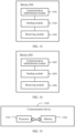
- FIG. 11 is a schematic diagram of a structure of a PIN creation apparatus according to an embodiment of this application.
- the apparatus may correspond to a user equipment in another embodiment, such as a PEMC.
- the apparatus 1100 includes the following modules:
- the sending module sends the networking request information to the PIN server.
- the networking request information is used to request to create the PIN.
- the receiving module receives the networking response information.
- the networking response information includes creation success information or the creation failure information. That is, after verifying the networking request information, the PIN server may agree or disagree to a networking request.
- Embodiments of this application enable the user equipment to create the PIN. This is conducive to meeting a requirement of communication between devices by using the PIN.
- the creation failure information indicates that the networking request is not agreed to, and the PIN server may indicate the reason for this networking failure.
- the networking request information includes at least one of the following: (1) life cycle information of the PIN, where the life cycle information is used to indicate a time when the PIN takes effect or exists; (2) identifier information related to the apparatus; (3) an IP address or a port number of the apparatus; (4) information of a PIN element that the apparatus expects to add to the PIN; (5) information of a PEGC in the PIN; and (6) a security credential.
- the identifier information related to the apparatus includes at least one of the following: an identifier ID of a PEMC in the PIN, an enabler ID of the apparatus, an SUPI of the apparatus, a GPSI of the apparatus, an application ID on the PEMC in the PIN, and an enabled client ID of the PEMC in the PIN.
- the information of the PIN element includes at least one of the following: an ID of the PIN element, an enabler ID of the PIN element, a user equipment ID of the PIN element, the application ID on the PEMC in the PIN, an IP address of the PIN element, and an enabler IP address of the PIN element.
- the information of the PEGC includes at least one of the following: an ID of the PEGC, an enabler ID of the PEGC, a user equipment ID of the PEGC, an application ID on the PEGC, and an IP address of the PEGC.
- the access control information includes at least one of the following: a user name, an account number, a password, an SSID, and a BSSID; and/or the routing information includes at least one of the following: an IP address of a UPF, a port number of the UPF, an FQDN of the UPF, and a data network DN connected by using the UPF, where the PEGC visits the target network by accessing the UPF.
- the apparatus determine the PEGC in the PIN in at least one of the following manners.
- the PEGC subscribes to or registers in the apparatus.
- the creation success information includes the information of the PEGC.
- the PIN element in the PIN managed by the apparatus visits the target network by using the determined PEGC in the PIN.
- the apparatus in a case that the PEGC subscribes to or registers in the apparatus, the apparatus establishes a communication connection to the PEGC through non-3GPP access.
- the receiving module 1104 receives first registration request information from the PEGC, and verifies the first registration request information.
- the sending module 1102 sends first registration response information.
- the first registration response information includes registration success information or registration failure information, the registration success information indicates that the first registration request information has been verified, and the registration failure information indicates that the first registration request information fails to be verified.
- the first registration request information includes at least one of the following: the ID of the PEGC, the enabler ID of the PEGC, an ID of the user equipment, the application ID on the PEGC, the IP address of the PEGC, a security credential, access control information, and routing information; and/or the first registration response information includes at least one of the following: a registration ID, registration termination time information, and a context ID of the PEGC.
- the apparatus is further configured to establish a communication connection to the PIN element through a non-3GPP access.
- the receiving module 1104 is configured to: receive second registration request information from the PIN element; and in a case that a second registration request has been verified, add the PIN element to the PIN.
- the sending module 1102 is configured to send second registration response information.
- the second registration request information includes at least one of the following: the ID of the PIN element, the enabler ID of the PIN element, an application ID on the PIN element, the IP address of the PIN element, and the security credential; and/or the second registration response information includes at least one of the following: the registration ID, the registration termination time information, a context ID of the PIN element, and an ID of the PIN.
- the apparatus is further configured to determine permission of the PIN element.
- the second registration response information further includes at least one of the following: (1) an IP address of the PEGC in the PIN; (2) a port number of the PEGC in the PIN; and (3) access permission of the PIN element, where the access permission includes whether the PIN element supports access to the target network by using the PEGC in the PIN.
- the access permission of the PIN element is obtained by the apparatus from the PIN server, or is determined by the apparatus based on registration information of the PEGC.
- the sending module 1102 is configured to send subscription request information to the PIN server.
- the subscription request information is used to request at least one of the following: becoming a PEMC; and registering in or subscribing to an operator network.
- the receiving module 1104 is configured to receive subscription success information from the PIN server. The subscription success information indicates that the apparatus becomes a PEMC.
- the subscription request information includes at least one of the following: the application ID on the PEMC, an SUPI of the apparatus, a GPSI of the apparatus, an IP address of the apparatus, a PEMC client IP address, and the security credential.
- the apparatus 1100 according to this embodiment of this application may correspond to the processes of the method 200 in embodiments of this application, and units/modules in the apparatus 1100 and the foregoing operations and/or functions are separately for implementing the corresponding processes of the method 200, and a same or equivalent technical effect can be achieved. For brevity, details are not described herein again.
- FIG. 12 is a schematic diagram of a structure of a PIN creation apparatus according to an embodiment of this application.
- the apparatus may correspond to a PIN server in another embodiment.
- the apparatus 1200 includes the following modules:
- the apparatus 1200 receives the networking request information.
- the networking request information is used to request to create the PIN.
- the apparatus 1200 sends the networking response information to the user equipment.
- the networking response information includes the creation success information or the creation failure information. That is, after verifying the networking request information, the apparatus 1200 may agree or disagree to a networking request of the user equipment.
- Embodiments of this application enable the user equipment to create the PIN. This is conducive to meeting a requirement of communication between devices by using the PIN.
- the creation failure information indicates that the networking request is not agreed to, and the apparatus 1200 may indicate the reason for this networking failure.
- the networking request information includes at least one of the following: (1) life cycle information of the PIN, where the life cycle information is used to indicate a time when the PIN takes effect or exists; (2) identifier information related to the user equipment; (3) an IP address or a port number of the user equipment; (4) information of a PIN element that the user equipment expects to add to the PIN; (5) information of a PEGC in the PIN; and (6) a security credential.
- the identifier information related to the user equipment includes at least one of the following: an ID of a PEMC in the PIN, an enabler ID of the user equipment, an SUPI of the user equipment, a GPSI, an application ID on the PEMC in the PIN, and an enabled client ID of the PEMC.
- the information of the PIN element includes at least one of the following: an ID of the PIN element, an enabler ID of the PIN element, a user equipment ID of the PIN element, the application ID on the PEMC in the PIN, an IP address of the PIN element, and an enabler IP address of the PIN element.
- the information of the PEGC includes at least one of the following: an ID of the PEGC, an enabler ID of the PEGC, a user equipment ID of the PEGC, an application ID on the PEGC, and an IP address of the PEGC.
- the creation success information includes at least one of the following: (1) an identifier ID of the PIN; (2) the information of the PEGC in the PIN; (3) access control information configured to the PEGC in the PIN, where the access control information is used to control whether the PIN element in the PIN can visit or access a target network; and (4) routing information configured to the PEGC in the PIN, where the routing information is used for the PEGC or the PIN element in the PIN to visit the target network.
- the access control information includes at least one of the following: a user name, an account number, a password, an SSID, and a BSSID; and/or the routing information includes at least one of the following: an IP address of a UPF, a port number of the UPF, an FQDN of the UPF, and a data network DN connected by using the UPF, where the PEGC visits the target network by accessing the UPF.
- the sending module 1204 is configured to send the information of the PEGC in the PIN to the user equipment.
- the apparatus 1200 may correspond to the processes of the method 300 in embodiments of this application, and units/modules in the apparatus 1200 and the foregoing operations and/or functions are separately for implementing the corresponding processes of the method 300, and a same or equivalent technical effect can be achieved. For brevity, details are not described herein again.
- FIG. 13 is a schematic diagram of a structure of a PIN creation apparatus according to an embodiment of this application.
- the apparatus may correspond to a user equipment in another embodiment, such as a PEGC.
- the apparatus 1300 includes the following modules:
- the PIN creation apparatus provided by embodiments of this application can be applied to become the PEGC in the PIN.
- the PEGC enables a PIN element in the PIN to visit a 5G network or visit another service server by using the 5G network. This is conducive to meeting a communication requirement of the device by using the PIN.
- the first registration request information includes at least one of the following: an ID of the apparatus, an enabler ID of the apparatus, an application ID on the apparatus, an IP address of the apparatus, a security credential, access control information, and routing information; and/or the first registration response information includes at least one of the following: a registration ID, registration termination time information, and a context ID of the apparatus.
- the apparatus 1300 may correspond to the processes of the method 400 in embodiments of this application, and units/modules in the apparatus 1300 and the foregoing operations and/or functions are separately for implementing the corresponding processes of the method 400, and a same or equivalent technical effect can be achieved. For brevity, details are not described herein again.
- FIG. 14 is a schematic diagram of a structure of a PIN creation apparatus according to an embodiment of this application.
- the apparatus may correspond to a user equipment in another embodiment, such as a PIN element.
- the apparatus 1400 includes the following modules:
- the PIN creation apparatus provided by embodiments of this application can be applied to become the PIN element in the PIN.
- the PIN element can visit a 5G network by using a PEGC in the PIN or visit another service server by using the 5G network. This is conducive to meeting a communication requirement.
- the second registration request information includes at least one of the following: an ID of the apparatus, an enabler ID of the apparatus, an application ID on the apparatus, an IP address of the apparatus, and a security credential; and/or the second registration response information includes at least one of the following: a registration ID, registration termination time information, a context ID of the user equipment, an ID of the user equipment, and an ID of the user equipment.
- the second registration response information also includes at least one of the following: (1) an IP address of the PEGC in the PIN; (2) a port number of the PEGC in the PIN; and (3) access permission of the apparatus, where the access permission includes whether the apparatus supports access to a target network by using the PEGC in the PIN.
- the apparatus 1400 may correspond to the processes of the method 500 in embodiments of this application, and units/modules in the apparatus 1400 and the foregoing operations and/or functions are separately for implementing the corresponding processes of the method 500, and a same or equivalent technical effect can be achieved. For brevity, details are not described herein again.
- the PIN creation apparatus in embodiments of this application may be an electronic device, such as an electronic device with an operating system, or may be a component in the electronic device, such as an integrated circuit or chip.
- the electronic device may be a user equipment, or another device other than the user equipment.
- the user equipment may include but is not limited to the foregoing listed type of the user equipment 11.
- the another device may be a server, a network attached storage (Network Attached Storage, NAS), and the like. This is not specifically limited in embodiments of this application.
- the PIN creation apparatus provided in embodiments of this application can implement the processes implemented in the method embodiments of FIG. 2 to FIG. 10 , and a same technical effect can be achieved. To avoid repetition, details are not described herein again.
- an embodiment of this application further provides a communication device 1500, including a processor 1501, a memory 1502, and a program or an instruction stored in the memory 1502 and executable on the processor 1501.
- a communication device 1500 including a processor 1501, a memory 1502, and a program or an instruction stored in the memory 1502 and executable on the processor 1501.
- the communication device 1500 is a user equipment
- the program or the instruction is executed by the processor 1501
- the process steps of the PIN creation method embodiment are implemented, and a same technical effect can be achieved.
- the communication device 1500 is a network side device, when the program or the instruction is executed by the processor 1501, the steps of the PIN creation method embodiment are implemented, and a same technical effect can be achieved. To avoid repetition, details are not described herein again.
- An embodiment of this application further provides a user equipment, including a processor and a communication interface.
- the communication interface is configured to implement the steps of the method in the embodiment shown in FIG. 2 , FIG. 4 or FIG. 5 .
- the user equipment embodiment is corresponding to the foregoing user equipment side method embodiment, each implementation process and implementation of the method embodiment can be applied to the user equipment embodiment, and a same technical effect can be achieved.
- FIG. 16 is a schematic diagram of a hardware structure of a user equipment according to an embodiment of this application.
- the user equipment 1600 includes but is not limited to at least a part of components such as a radio frequency unit 1601, a network module 1602, an audio output unit 1603, an input unit 1604, a sensor 1605, a display unit 1606, a user input unit 1607, an interface unit 1608, a memory 1609, and a processor 1610.
- the user equipment 1600 may further include a power supply (such as a battery) that supplies power to each component.
- the power supply may be logically connected to the processor 1610 by using a power supply management system, to implement functions such as charging and discharging management, and power consumption management by using the power supply management system.
- the user equipment structure shown in FIG. 16 constitutes no limitation on the user equipment, and the user equipment may include more or fewer components than those shown in the figure, or combine some components, or have different component arrangements. Details are not described herein.
- the input unit 1604 may include a graphics processing unit (Graphics Processing Unit, GPU) 16041 and a microphone 16042.
- the graphics processing unit 16041 processes image data of a static picture or a video obtained by an image capture apparatus (for example, a camera) in a video capture mode or an image capture mode.
- the display unit 1606 may include a display panel 16061, and the display panel 16061 may be configured in a form of a liquid crystal display, an organic light-emitting diode, or the like.
- the user input unit 1607 includes at least one of a touch panel 16071 and another input device 16072.
- the touch panel 16071 is also referred to as a touchscreen.
- the touch panel 16071 may include two parts: a touch detection apparatus and a touch controller.
- the another input device 16072 may include but is not limited to a physical keyboard, a functional button (such as a volume control button or a power on/off button), a trackball, a mouse, and a joystick. Details are not described herein.
- the radio frequency unit 1601 receives downlink data from a network side device and then sends the downlink data to the processor 1610 for processing; and the radio frequency unit 1601 may send uplink data to the network side device.
- the radio frequency unit 1601 includes but is not limited to an antenna, an amplifier, a transceiver, a coupler, a low noise amplifier, a duplexer, and the like.
- the memory 1609 may be configured to store a software program or an instruction and various data.
- the memory 1609 may mainly include a first storage area for storing a program or an instruction and a second storage area for storing data.
- the first storage area may store an operating system, and an application or an instruction required by at least one function (for example, a sound playing function or an image playing function).
- the memory 1609 may be a volatile memory or a nonvolatile memory, or the memory 1609 may include a volatile memory and a nonvolatile memory.
- the nonvolatile memory may be a read-only memory (Read-Only Memory, ROM), a programmable read-only memory (Programmable ROM, PROM), an erasable programmable read-only memory (Erasable PROM, EPROM), an electrically erasable programmable read-only memory (Electrically EPROM, EEPROM), or a flash memory.
- ROM Read-Only Memory
- PROM programmable read-only memory
- Erasable PROM Erasable PROM
- EPROM electrically erasable programmable read-only memory
- EEPROM electrically erasable programmable read-only memory
- the volatile memory may be a random access memory (Random Access Memory, RAM), a static random access memory (Static RAM, SRAM), a dynamic random access memory (Dynamic RAM, DRAM), a synchronous dynamic random access memory (Synchronous DRAM, SDRAM), a double data rate synchronous dynamic random access memory (Double Data Rate SDRAM, DDRSDRAM), an enhanced synchronous dynamic random access memory (Enhanced SDRAM, ESDRAM), a synch link dynamic random access memory (Synch link DRAM, SLDRAM), and a direct rambus random access memory (Direct Rambus RAM, DRRAM).
- RAM Random Access Memory
- SRAM static random access memory
- DRAM dynamic random access memory
- DRAM synchronous dynamic random access memory
- SDRAM double data rate synchronous dynamic random access memory
- Enhanced SDRAM, ESDRAM enhanced synchronous dynamic random access memory
- Synch link DRAM, SLDRAM synch link dynamic random access memory
- Direct Rambus RAM Direct Rambus RAM
- the processor 1610 may include one or more processing units.
- an application processor and a modem processor are integrated into the processor 1610.
- the application processor mainly processes an operating system, a user interface, an application, or the like.
- the modem processor mainly processes a wireless communication signal, for example, a baseband processor. It may be understood that, alternatively, the modem processor may not be integrated into the processor 1610.
- the radio frequency unit 1601 can be configured to implement the steps of the method in the embodiment shown in FIG. 2 , FIG. 4 , or FIG. 5 .
- the user equipment 1600 provided in this embodiment of this application can implement the processes of the foregoing embodiment of the PIN creation method, and a same technical effect can be achieved. To avoid repetition, details are not described herein again.
- An embodiment of this application further provides a network side device, including a processor and a communication interface.
- the communication interface is configured to implement the steps of the method in the embodiment shown in FIG. 3 .
- This network side device embodiment is corresponding to the foregoing method embodiment of the network side device.
- Each implementation process and implementation of the foregoing method embodiment may be applicable to this network side device embodiment, and a same technical effect can be achieved.
- the network device 1700 includes: a processor 1701, a network interface 1702, and a memory 1703.
- the network interface 1702 is, for example, a common public radio interface (common public radio interface, CPRI).
- the network side device 1700 in this embodiment of this invention further includes an instruction or a program stored in the memory 1703 and executable on the processor 1701.
- the processor 1701 invokes the instruction or the program in the memory 1703 to perform the method performed by the modules shown in FIG. 12 , and a same technical effect is achieved. To avoid repetition, details are not described herein again.
- An embodiment of this application further provides a readable storage medium.
- the readable storage medium stores a program or an instruction.
- the processes of the foregoing PIN creation method embodiment are implemented, and a same technical effect can be achieved. To avoid repetition, details are not described herein again.
- the processor is a processor in the user equipment in the foregoing embodiment.
- the readable storage medium includes a computer-readable storage medium, such as a computer read-only memory ROM, a random access memory RAM, a magnetic disk, or an optical disc.
- An embodiment of this application further provides a chip.
- the chip includes a processor and a communication interface, the communication interface is coupled to the processor, and the processor is configured to run a program or an instruction to implement the processes of the foregoing PIN creation method embodiment, and a same technical effect can be achieved. To avoid repetition, details are not described herein again.
- the chip mentioned in this embodiment of this application may also be referred to as a system-level chip, a system chip, a chip system, or a system on chip.
- An embodiment of this application further provides a computer program/program product.
- the computer program/program product is stored in a storage medium, and the program/program product is executed by at least one processor to implement the processes of the foregoing PIN creation method embodiment, and a same technical effect can be achieved. To avoid repetition, details are not described herein again.
- An embodiment of this application further provides a PIN creation system, including a user equipment and a network side device.
- the user equipment may be configured to perform the steps of the PIN creation method
- the network side device may be configured to perform the steps of the PIN creation method.
- the method in the foregoing embodiment may be implemented by software in addition to a necessary universal hardware platform or by hardware only. In most circumstances, the former is a preferred implementation. Based on such an understanding, the technical solutions of this application essentially or the part contributing to the prior art may be implemented in a form of a computer software product.
- the computer software product is stored in a storage medium (for example, a ROM/RAM, a floppy disk, or an optical disc), and includes several instructions for instructing a user equipment (which may be a mobile phone, a computer, a server, an air conditioner, a network device, or the like) to perform the methods described in embodiments of this application.
Landscapes
- Engineering & Computer Science (AREA)
- Computer Security & Cryptography (AREA)
- Computer Networks & Wireless Communication (AREA)
- Signal Processing (AREA)
- Computing Systems (AREA)
- Health & Medical Sciences (AREA)
- General Health & Medical Sciences (AREA)
- Medical Informatics (AREA)
- Mobile Radio Communication Systems (AREA)
Applications Claiming Priority (2)
| Application Number | Priority Date | Filing Date | Title |
|---|---|---|---|
| CN202210112394.4A CN116567778B (zh) | 2022-01-29 | 2022-01-29 | Pin的组建方法及设备 |
| PCT/CN2023/073662 WO2023143554A1 (zh) | 2022-01-29 | 2023-01-29 | Pin的组建方法及设备 |
Publications (2)
| Publication Number | Publication Date |
|---|---|
| EP4468786A1 true EP4468786A1 (de) | 2024-11-27 |
| EP4468786A4 EP4468786A4 (de) | 2025-04-23 |
Family
ID=87470706
Family Applications (1)
| Application Number | Title | Priority Date | Filing Date |
|---|---|---|---|
| EP23746431.8A Pending EP4468786A4 (de) | 2022-01-29 | 2023-01-29 | Pin-herstellungsverfahren und -vorrichtung |
Country Status (4)
| Country | Link |
|---|---|
| US (1) | US20240388912A1 (de) |
| EP (1) | EP4468786A4 (de) |
| CN (1) | CN116567778B (de) |
| WO (1) | WO2023143554A1 (de) |
Families Citing this family (2)
| Publication number | Priority date | Publication date | Assignee | Title |
|---|---|---|---|---|
| CN118945695A (zh) * | 2023-05-12 | 2024-11-12 | 维沃移动通信有限公司 | 信息处理方法、信息传输方法、装置及相关设备 |
| CN119728709A (zh) * | 2023-09-27 | 2025-03-28 | 维沃移动通信有限公司 | 信息同步方法、服务切换方法、请求处理方法及设备 |
Family Cites Families (7)
| Publication number | Priority date | Publication date | Assignee | Title |
|---|---|---|---|---|
| CN106856443A (zh) * | 2015-12-08 | 2017-06-16 | 中兴通讯股份有限公司 | 家庭物联网的实现方法及机顶盒、物联网服务器 |
| CN109756450B (zh) * | 2017-11-03 | 2021-06-15 | 华为技术有限公司 | 一种物联网通信的方法、装置、系统和存储介质 |
| CN108306938B (zh) * | 2017-12-29 | 2021-08-24 | 青岛海尔科技有限公司 | 一种物联产品自动入网的方法、装置及网关 |
| CN113574936B (zh) * | 2019-08-02 | 2024-07-09 | Oppo广东移动通信有限公司 | 无线通信的方法、终端设备和网络设备 |
| US20210368341A1 (en) * | 2020-08-10 | 2021-11-25 | Ching-Yu LIAO | Secure access for 5g iot devices and services |
| CN112804730B (zh) * | 2021-01-25 | 2023-09-08 | Oppo广东移动通信有限公司 | 设备互联方法、装置、服务器、智能设备及存储介质 |
| CN113489695B (zh) * | 2021-06-24 | 2023-08-01 | 深圳Tcl新技术有限公司 | 私有云组网方法、装置、系统、计算机设备及存储介质 |
-
2022
- 2022-01-29 CN CN202210112394.4A patent/CN116567778B/zh active Active
-
2023
- 2023-01-29 WO PCT/CN2023/073662 patent/WO2023143554A1/zh not_active Ceased
- 2023-01-29 EP EP23746431.8A patent/EP4468786A4/de active Pending
-
2024
- 2024-07-29 US US18/787,606 patent/US20240388912A1/en active Pending
Also Published As
| Publication number | Publication date |
|---|---|
| EP4468786A4 (de) | 2025-04-23 |
| US20240388912A1 (en) | 2024-11-21 |
| CN116567778A (zh) | 2023-08-08 |
| CN116567778B (zh) | 2026-02-24 |
| WO2023143554A1 (zh) | 2023-08-03 |
Similar Documents
| Publication | Publication Date | Title |
|---|---|---|
| WO2023116786A1 (zh) | 物联网设备的注册方法、装置、通信设备、核心网设备、存储介质及系统 | |
| US20240388912A1 (en) | PIN Creation Method and Device | |
| WO2023143418A1 (zh) | 设备鉴权方法、装置、终端及网络功能 | |
| WO2024120352A1 (zh) | 通信方法、终端及核心网功能 | |
| WO2023179595A1 (zh) | 非3gpp设备的会话通道建立方法、装置及设备 | |
| CN116567626B (zh) | 设备鉴权方法、装置及通信设备 | |
| WO2023131286A1 (zh) | 资源控制方法、装置、终端、网络侧设备及可读存储介质 | |
| WO2023143416A1 (zh) | 信息处理方法、终端及网络功能 | |
| CN118042452A (zh) | 操作执行方法、装置、终端及网络功能 | |
| WO2024061091A1 (zh) | 一种网络通信的方法、装置、网络侧设备、终端及介质 | |
| CN116567779A (zh) | Pin的组建方法及设备 | |
| WO2023143423A1 (zh) | 信息获取与存储、上报方法、装置、终端及网络功能 | |
| CN117177229A (zh) | 数据传输方法、装置、通信设备及网元 | |
| CN116828546A (zh) | 非3gpp设备的会话通道建立方法、装置及设备 | |
| US20250175924A1 (en) | Method and apparatus for registering pin device, and communication device | |
| CN116567777B (zh) | 接入参数使用方法、终端及网络侧 | |
| CN116567591B (zh) | 直连空口配置方法、终端及网络侧设备 | |
| US20250323958A1 (en) | Communication Method, User Equipment, and Network Side Device | |
| EP4503720A1 (de) | Verfahren zur aushandlung einer nicht verfügbaren periode eines endgeräts, endgerät und netzwerkseitige vorrichtung | |
| US20260067790A1 (en) | Information processing method and apparatus, information transmission method and apparatus, and related device | |
| CN117858083A (zh) | 个人物联网中设备认证方法、装置及通信设备 | |
| WO2024022182A1 (zh) | 信息查询方法、装置、终端及网络侧设备 | |
| WO2024140570A1 (zh) | 策略配置方法、装置、终端、网络侧设备及可读存储介质 | |
| CN120186595A (zh) | 通信方法、终端及网络侧设备 | |
| WO2025067044A1 (zh) | 信息同步方法、服务切换方法、请求处理方法及设备 |
Legal Events
| Date | Code | Title | Description |
|---|---|---|---|
| STAA | Information on the status of an ep patent application or granted ep patent |
Free format text: STATUS: THE INTERNATIONAL PUBLICATION HAS BEEN MADE |
|
| PUAI | Public reference made under article 153(3) epc to a published international application that has entered the european phase |
Free format text: ORIGINAL CODE: 0009012 |
|
| STAA | Information on the status of an ep patent application or granted ep patent |
Free format text: STATUS: REQUEST FOR EXAMINATION WAS MADE |
|
| 17P | Request for examination filed |
Effective date: 20240819 |
|
| AK | Designated contracting states |
Kind code of ref document: A1 Designated state(s): AL AT BE BG CH CY CZ DE DK EE ES FI FR GB GR HR HU IE IS IT LI LT LU LV MC ME MK MT NL NO PL PT RO RS SE SI SK SM TR |
|
| A4 | Supplementary search report drawn up and despatched |
Effective date: 20250320 |
|
| RIC1 | Information provided on ipc code assigned before grant |
Ipc: H04W 12/108 20210101ALI20250314BHEP Ipc: H04W 12/69 20210101ALI20250314BHEP Ipc: H04W 12/50 20210101ALI20250314BHEP Ipc: H04W 4/70 20180101ALI20250314BHEP Ipc: H04L 67/12 20220101ALI20250314BHEP Ipc: H04W 48/16 20090101ALI20250314BHEP Ipc: G16Y 30/00 20200101ALI20250314BHEP Ipc: H04W 48/08 20090101AFI20250314BHEP |
|
| DAV | Request for validation of the european patent (deleted) | ||
| DAX | Request for extension of the european patent (deleted) |