EP4468738A2 - Earphone box and earphone - Google Patents
Earphone box and earphone Download PDFInfo
- Publication number
- EP4468738A2 EP4468738A2 EP24206115.8A EP24206115A EP4468738A2 EP 4468738 A2 EP4468738 A2 EP 4468738A2 EP 24206115 A EP24206115 A EP 24206115A EP 4468738 A2 EP4468738 A2 EP 4468738A2
- Authority
- EP
- European Patent Office
- Prior art keywords
- earphone
- box
- magnet
- accommodating groove
- interface
- Prior art date
- Legal status (The legal status is an assumption and is not a legal conclusion. Google has not performed a legal analysis and makes no representation as to the accuracy of the status listed.)
- Pending
Links
Images


Classifications
-
- H—ELECTRICITY
- H04—ELECTRIC COMMUNICATION TECHNIQUE
- H04R—LOUDSPEAKERS, MICROPHONES, GRAMOPHONE PICK-UPS OR LIKE ACOUSTIC ELECTROMECHANICAL TRANSDUCERS; ELECTRIC HEARING AIDS; PUBLIC ADDRESS SYSTEMS
- H04R1/00—Details of transducers, loudspeakers or microphones
- H04R1/10—Earpieces; Attachments therefor ; Earphones; Monophonic headphones
- H04R1/1016—Earpieces of the intra-aural type
-
- H—ELECTRICITY
- H01—ELECTRIC ELEMENTS
- H01F—MAGNETS; INDUCTANCES; TRANSFORMERS; SELECTION OF MATERIALS FOR THEIR MAGNETIC PROPERTIES
- H01F7/00—Magnets
- H01F7/02—Permanent magnets [PM]
- H01F7/0231—Magnetic circuits with PM for power or force generation
- H01F7/0252—PM holding devices
-
- H—ELECTRICITY
- H04—ELECTRIC COMMUNICATION TECHNIQUE
- H04R—LOUDSPEAKERS, MICROPHONES, GRAMOPHONE PICK-UPS OR LIKE ACOUSTIC ELECTROMECHANICAL TRANSDUCERS; ELECTRIC HEARING AIDS; PUBLIC ADDRESS SYSTEMS
- H04R1/00—Details of transducers, loudspeakers or microphones
- H04R1/10—Earpieces; Attachments therefor ; Earphones; Monophonic headphones
- H04R1/1058—Manufacture or assembly
-
- H—ELECTRICITY
- H04—ELECTRIC COMMUNICATION TECHNIQUE
- H04R—LOUDSPEAKERS, MICROPHONES, GRAMOPHONE PICK-UPS OR LIKE ACOUSTIC ELECTROMECHANICAL TRANSDUCERS; ELECTRIC HEARING AIDS; PUBLIC ADDRESS SYSTEMS
- H04R1/00—Details of transducers, loudspeakers or microphones
- H04R1/10—Earpieces; Attachments therefor ; Earphones; Monophonic headphones
- H04R1/1025—Accumulators specially adapted for earpieces; Arrangements specially adapted for charging thereof
-
- H—ELECTRICITY
- H04—ELECTRIC COMMUNICATION TECHNIQUE
- H04R—LOUDSPEAKERS, MICROPHONES, GRAMOPHONE PICK-UPS OR LIKE ACOUSTIC ELECTROMECHANICAL TRANSDUCERS; ELECTRIC HEARING AIDS; PUBLIC ADDRESS SYSTEMS
- H04R2460/00—Details of hearing devices, i.e. of ear- or headphones covered by H04R1/10 or H04R5/033 but not provided for in any of their subgroups, or of hearing aids covered by H04R25/00 but not provided for in any of its subgroups
- H04R2460/17—Hearing device specific tools used for storing or handling hearing devices or parts thereof, e.g. placement in the ear, replacement of cerumen barriers, repair, cleaning hearing devices
Definitions
- the present invention relates to the field of earphone box technologies, and more particularly, to an earphone box and an earphone.
- TWS true wireless stereo
- earphones are mainly classified into two types: earphones with a bud shape and earphones with a stem shape.
- the earphone is in contact with and compresses a pogopin (also referred to as pogo pin) in an earphone box by a copper column on the earphone when it is placed into the earphone box, to realize a charging process of the earphone by the earphone box.
- a pogopin also referred to as pogo pin
- an inner housing of the earphone box has a shape similar to a shape of the earphone; a position of the earphone in the earphone box is restricted by the shape; moreover, in order to ensure the charging reliability of the placed earphone, the copper column of the earphone and the pogopin of the earphone charging box are both oriented along a vertical direction, which is consistent with the gravity direction of the earphone, to reduce a mutual dislocation between the copper column and the pogopin caused by the gravity component.
- the present invention aims to solve at least one of the technical problems in the related art to a certain extent.
- embodiments of the present invention provide an earphone box and an earphone.
- the earphone box includes a box body and a box magnet.
- the box body defines an accommodating groove for accommodating the earphone, and the accommodating groove is provided with an interface electrically coupled to the earphone.
- the box magnet is mounted on the box body and configured as a multipole magnet, and the box magnet is configured to attract and couple with an earphone magnet of the earphone which has the same number of poles as the box magnet.
- An earphone box in the related art has following disadvantages: a low utilization rate of an internal space, a large overall volume and the inconvenient carrying, and the earphone is inconvenient to take out of the earphone box.
- the earphone box 1000 includes the box body 1001, the box cover 1002 and the box magnet 200.
- each of the box magnet 200 and the earphone magnet 310 is a two-pole magnet.
- the two-pole magnet has a small volume, is convenient to mount and reduces the volume of the box body 1001.
- the two-point positioning between the box magnet 200 and the earphone magnet 310 can be realized by the two-pole magnet, to improve the positioning effect between the earphone 300 and the box body 1001.
- two poles on the attraction face of the earphone magnet 310 of the two-pole magnet and two poles on the attraction face of the box magnet 200 of the two-pole magnet can attract each other together correspondingly, to realize the two-point positioning effect, so that the positioning effect between the earphone magnet 310 and the box magnet 200 is good or improved.
- the earphone magnet 310 and the box magnet 200 are two-pole magnets, to increase the attraction force between the earphone magnet 310 and the box magnet 200, so that the positioning effect between the earphone magnet 310 and the box magnet 200 is further improved. That is, the positioning effect between the earphone 300 and the box body 1001 is improved, so that the earphone 300 is more stable and not easy to change its position when it is attracted on the box body 1001. Thus, the earphone 300 is more stable when charging in the box body 1001, and the charging effect is good or improved.
- the box magnet 200 includes a first box magnet 210 and a second box magnet 220 arranged in the box body 1001. At least part of the first box magnet 210 is exposed in the left accommodating groove 110, and at least part of the second box magnet 220 is exposed in the right accommodating groove 120.
- An exposed face (an attraction face) of at least a part of the first box magnet 210 has a plurality of poles, and an exposed face (the attraction face) of at least a part of the second box magnet 220 has a plurality of poles.
- the box body 1001 includes a first inclined face 111 constituting at least part of a side wall of the left accommodating groove 110 and a second inclined face 121 constituting at least part of a side wall of the right accommodating groove 120.
- the first inclined face 111 can allow the left earphone to be placed obliquely in the left accommodating groove 110
- the second inclined face 121 can allow the right earphone to be placed obliquely in the right accommodating groove 120, to improve the utilization rate of the space of the box body 1001, which is conducive to reducing the volume of the box body 1001, so that box body 1001 is easy to carry.
- a polarity distribution at the outer surface 211 of the first box magnet 210 is different from a polarity distribution at the outer surface 221 of the second box magnet 220.
- an upper portion of the outer surface 211 of the first box magnet 210 is N pole and an lower portion thereof is S pole
- an upper portion of the outer surface 221 of the second box magnet 220 is S pole and an lower portion thereof is N pole
- a left portion of the outer surface 211 of the first box magnet 210 is N pole and a right portion thereof is S pole
- a left portion of the outer surface 221 of the second box magnet 220 is S pole and a right portion thereof is N pole.
- the interface 130 includes a left interface 131 arranged in the left accommodating groove 110 and a right interface 132 arranged in the right accommodating groove 120.
- the left interface 131 may be electrically coupled to the left earphone, to charge the left earphone
- the right interface 132 may be electrically coupled to the right earphone, to charge the right earphone.
- the axis of the right interface 132 can be arranged obliquely relative to the up-down direction, and the axis of the right interface 132 can be substantially perpendicular to the second inclined face 121, to facilitate an electrical coupling between the right earphone and the right interface 132, i.e., to facilitate the right interface 132 to stably charge the right earphone.
- an angle included between the axis of each of the left interface 131 and the right interface 132 and a plane defined by the left-right direction and by the front-rear direction of the earphone box 1000 is 45°-55°.
- the box body 1001 has a smaller volume and is easy to carry while facilitating the left interface 131/the right interface 132 to stably charge the left earphone/the right earphone.
- the left interface 131 is arranged on the first inclined face 111 and adjacent to the first box magnet 210. Therefore, after the left earphone enters into the left accommodating groove 110, it can be electrically coupled to the left interface 131 conveniently. Moreover, a position between the first box magnet 210 of the left earphone and the earphone magnet 310 of the left earphone has a strong attraction force, thus realizing the good positioning effect.
- the left interface 131 is adjacent to the first box magnet 210, so that the left earphone and the left interface 131 are coupled stably, i.e., the charging of the left earphone is more stable.
- each of the left interface 131 and the right interface 132 is a pogopin
- the left earphone and the right earphone are each provided with a coupling copper column for abutting with a spring pin 133 of pogopin.
- two spring pins 133 of pogopin are provided, and located at two sides of the box magnet 200.
- the left interface 131 includes two spring pins 133 of pogopin, and the two spring pins 133 of pogopin of the left interface 131 are located at two opposite sides of the first box magnet 210; and the right interface 132 includes two spring pins 133 of pogopin, and the two spring pins 133 of pogopin of the right interface 132 are located at two opposite sides of the second box magnet 220.
- the coupling copper columns of the left earphone press the spring pins 133 of the left interface 131, to create the electrical coupling between the left earphone and the left interface 131, so that the charging of the left earphone is stable.
- the coupling copper columns of the right earphone press the spring pins 133 of the right interface 132, to create the electrical coupling between the right earphone and the right interface 132, so that the charging of the right earphone is stable.
- each of the first inclined face 111 and the second inclined face 121 is a frosted face. Therefore, when the left earphone is placed on the first inclined face 111, a friction is large, so that the left earphone is not easy to move and the positioning effect is good. When the right earphone is placed on the second inclined face 121, a friction is large, so that the right earphone is not easy to move and the positioning effect is good.
- the first box magnet 210 and the left interface 131 are arranged on the first inclined face 111 with the frosted face, so that the left earphone can be fixed and electrically coupled only by contacting the first inclined face 111.
- the left earphone can be arranged obliquely, maximizing utilization rate of the space of the box body 1001 and reducing the volume of the box body 1001.
- the left accommodating groove 110 does not have to be limited to the profile of the earphone thereby realizing the reliability of charging also when the earphone is fitted with different shapes of different specifications of ear caps or sleeves.
- the second box magnet 220 and the right interface 132 are arranged on the second inclined face 121 with the frosted face, so that the right earphone can be fixed and electrically coupled only by contacting the second inclined face 121.
- the right earphone can be arranged obliquely, maximizing utilization rate of the space of the box body 1001 and reducing the volume of the box body 1001.
- the right accommodating groove 120 does not have be limited to the profile of the earphone thereby realizing the reliability of charging also when the earphone is fitted with different shapes of different specifications of ear caps or sleeves.
- the first inclined face 111 is inclined towards the right accommodating groove 120, so that the left earphone accommodated in the left accommodating groove 110 faces towards the right accommodating groove 120.
- the second inclined face 121 is inclined towards the left accommodating groove 110, so that the right earphone accommodated in the right accommodating groove 120 is inclined towards the left accommodating groove 110.
- the box body 1001 further includes a lower mounting cavity 140 spaced apart from the accommodating groove 100, the box cover 1002 defines an upper mounting cavity 150, the lower mounting cavity 140 is provided with a Hall sensor 141, and the upper mounting cavity 150 is provided with a Hall magnet 151.
- the lower mounting cavity 140 is located below the accommodating groove 100, and the upper mounting cavity 150 is located above the accommodating groove 100.
- the Hall sensor 141 in the lower mounting cavity 140 can cooperate with the Hall magnet 151 in the upper mounting cavity 150 using the Hall effect.
- the Hall sensor 141 detects information and sends the information to the earphone 300, so that a Bluetooth of the earphone 300 is turned on and the earphone 300 is automatically paired with the mobile phone.
- the upper mounting cavity 150 is provided with a first attraction magnet 152
- the lower mounting cavity 140 is provided with a second attraction magnet 142
- the second attraction magnet 142 is configured to attract and couple with the first attraction magnet 152 when the box cover 1002 closes the accommodating groove.
- the earphone 300 includes an earphone body 310 configured as a bud shape, and the earphone body 310 is adapted to fit in the accommodating groove 100 of the earphone box 1000 according to any one of the above embodiments.
- the earphone 300 according to embodiments of the present invention can be obliquely placed in the accommodating groove 100 in the earphone box 1000, has a good positioning effect and can be charged stably. Moreover, after the earphone 300 is placed in the accommodating groove 100, the overall volume is small and the earphone 300 is easy to carry.
- the earphone 300 further includes a plurality of earphone caps or sleeves 320 of different specifications.
- Each of the plurality of earphone sleeves 320 is adapted to be fitted over the earphone body 310, and the earphone body 310 fitted with any earphone sleeve 320 can fit in the accommodating groove 100.
- a space of the accommodating groove 100 is larger than a total volume of the earphone body 310 and the earphone sleeve 320 fitted over a side of the earphone body 310.
- the earphone 300 can be put into the accommodating groove 100 for charging and storage without removing the earphone sleeve 320.
- the earphone box 1000 has a strong adaptability.
- a 1 st embodiment provides an earphone box (1000), comprising:
- a 2 nd embodiment provides the earphone box (1000) according to the 1 st embodiment, wherein each of the box magnet (200) and the earphone magnet (310) is a two-pole magnet.
- a 3 rd embodiment provides the earphone box (1000) according to the 1 st embodiment or the 2 nd embodiment, wherein
- a 4 th embodiment provides the earphone box (1000) according to the 3 rd embodiment, wherein
- a 5 th embodiment provides the earphone box (1000) according to the 3rf embodiment or the 4 th embodiment, wherein
- a 6 th embodiment provides the earphone box (1000) according to any one of the 3 rd to 5 th embodiments, wherein a polarity distribution at an outer surface (211) of the first box magnet (210) is different from a polarity distribution at the outer surface (221) of the second box magnet (220).
- a 7 th embodiment provides the earphone box (1000) according to the 6 th embodiment, wherein
- An 8 th embodiment provides the earphone box (1000) according to any one of the 3 rd to 7 th embodiments, wherein
- a 9 th embodiment provides the earphone box (1000) according to the 8 th embodiment, wherein an angle included between the axis of each of the left interface (131) and the right interface (132) and a horizontal plane is 45°-55°.
- a 10 th embodiment provides the earphone box (1000) according to any one of the 5 th to 9 th embodiments, wherein each of the first inclined face (111) and the second inclined face (121) is a frosted face.
- An 11 th embodiment provides the earphone box (1000) according to any one of the 1 st to 10 th embodiments, wherein
- a 12 th embodiment provides the earphone box (1000) according to the 11 th embodiment, wherein
- a 13 th embodiment provides the earphone box (1000) according to any one of the 1 st to 12 th embodiments, wherein the interface (130) is provided with a pogopin having two spring pins (133), and the box magnet (200) is arranged between the two spring pins (133) of the pogopin.
- a 14 th embodiment provides the earphone (300), comprising an earphone body (310) configured as a bud shape, the earphone body (310) being adapted to fit in an accommodating groove (100) of an earphone box (1000) according to any one of the 1 st to 13 th embodiments.
- a 15 th embodiment provides the earphone (300) according to the 14 th embodiment, wherein
- first and second are merely used for descriptive purposes and cannot be understood as indicating or implying relative importance or the number of technical features indicated.
- the features associated with “first” and “second” may explicitly or implicitly include at least one of the features.
- a plurality of means at least two, such as two, three, etc.
- the terms “mounted,” “connected,” “coupled,” “fixed” and the like are used broadly, and may be, for example, fixed couplings, detachable couplings, or integral couplings; may also be mechanical or electrical couplings or intercommunication; may also be direct couplings or indirect couplings via intervening structures; may also be inner communications or interactions of two elements, which can be understood by those skilled in the art according to specific situations.
- a structure in which a first feature is "on" or “below” a second feature may include an embodiment in which the first feature is in direct contact with the second feature, and may also include an embodiment in which the first feature and the second feature are not in direct contact with each other, but are contacted via an additional feature formed therebetween.
- a first feature "on,” “above,” or “on top of” a second feature may include an embodiment in which the first feature is right or obliquely “on,” “above,” or “on top of” the second feature, or just means that the first feature is at a height higher than that of the second feature; while a first feature “below,” “under,” or “on bottom of” a second feature may include an embodiment in which the first feature is right or obliquely “below,” “under,” or “on bottom of” the second feature, or just means that the first feature is at a height lower than that of the second feature.
Landscapes
- Engineering & Computer Science (AREA)
- Physics & Mathematics (AREA)
- Acoustics & Sound (AREA)
- Signal Processing (AREA)
- Manufacturing & Machinery (AREA)
- Electromagnetism (AREA)
- Power Engineering (AREA)
- Casings For Electric Apparatus (AREA)
Abstract
Description
- The present invention relates to the field of earphone box technologies, and more particularly, to an earphone box and an earphone.
- Existing TWS (true wireless stereo) earphones are mainly classified into two types: earphones with a bud shape and earphones with a stem shape. The earphone is in contact with and compresses a pogopin (also referred to as pogo pin) in an earphone box by a copper column on the earphone when it is placed into the earphone box, to realize a charging process of the earphone by the earphone box. Ensuring that the copper column of the earphone is in full contact with the pogopin of the earphone box to realize the charging of the earphone when the earphone is placed into the earphone box, is typically implemented as follows: an inner housing of the earphone box has a shape similar to a shape of the earphone; a position of the earphone in the earphone box is restricted by the shape; moreover, in order to ensure the charging reliability of the placed earphone, the copper column of the earphone and the pogopin of the earphone charging box are both oriented along a vertical direction, which is consistent with the gravity direction of the earphone, to reduce a mutual dislocation between the copper column and the pogopin caused by the gravity component.
- The present invention aims to solve at least one of the technical problems in the related art to a certain extent.
- To this end, embodiments of the present invention provide an earphone box and an earphone.
- The earphone box according to embodiments of the present invention includes a box body and a box magnet. The box body defines an accommodating groove for accommodating the earphone, and the accommodating groove is provided with an interface electrically coupled to the earphone. The box magnet is mounted on the box body and configured as a multipole magnet, and the box magnet is configured to attract and couple with an earphone magnet of the earphone which has the same number of poles as the box magnet.
- The earphone box according to embodiments of the present invention, when compared to conventional approaches, has the advantages of providing a better or improved positioning effect, allowing for a more stable charging, realizing a smaller volume and allowing for an easier carrying.
- In some embodiments, the box magnet and the earphone magnet are both a two-pole magnet.
- In some embodiments, the accommodating groove includes a left accommodating groove for accommodating a left earphone and a right accommodating groove for accommodating a right earphone, the box magnet includes a first box magnet and a second box magnet arranged in the box body, the first box magnet is configured to attract and couple with earphone magnet of the left earphone, and the second box magnet is configured to attract and couple with the earphone magnet of the right earphone.
- In some embodiments, the box body includes a first inclined face constituting at least part of a side wall of the left accommodating groove and a second inclined face constituting at least part of a side wall of the right accommodating groove, the first box magnet is arranged on the first inclined face with an outer surface of the first box magnet being flush with the first inclined face, and the second box magnet is arranged on the second inclined face with an outer surface of the second box magnet being flush with the second inclined face.
- In some embodiments, a polarity distribution at the outer surface of the first box magnet is different from a polarity distribution at the outer surface of the second box magnet.
- In some embodiments, the interface includes a left interface arranged in the left accommodating groove and a right interface arranged in the right accommodating groove, and an axis of the left interface and an axis of the right interface are arranged obliquely.
- In some embodiments, an angle included between the axis of each of the left interface and the right interface and a horizontal plane is 45° -55°.
- In some embodiments, the first inclined face and the second inclined face are both a frosted face.
- In some embodiments, the earphone box further includes a box cover coupled to the box body, the box body further includes a lower mounting cavity separated from the accommodating groove, the box cover defines an upper mounting cavity, the lower mounting cavity is provided with a Hall sensor, and the upper mounting cavity is provided with a Hall magnet.
- In some embodiments, the upper mounting cavity is provided with a first attraction magnet, the lower mounting cavity is provided with a second attraction magnet, and the second attraction magnet is configured to attract and couple with the first attraction magnet when the box cover closes the accommodating groove.
- The earphone according to embodiments of the present invention includes a body configured as a bud shape, and the body is adapted to fit in the accommodating groove of the earphone box according to any of the above embodiments.
- The earphone according to embodiments of the present invention can be obliquely placed in the accommodating groove in the earphone box, thereby improving the positioning effect and allowing the earphone to be charged more stably. Moreover, after the earphone is placed in the accommodating groove, the overall volume is small and the earphone is easy to carry.
- In some embodiments, the earphone further includes a plurality of earphone sleeves of different specifications, each of the plurality of earphone sleeves is adapted to be fitted over the body, and the body fitted with any earphone sleeve is able to fit in an accommodating groove.
-
-
Fig. 1 is a front view of an earphone box according to an embodiment of the present invention. -
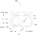
Fig. 2 is a top view of an earphone box according to an embodiment of the present invention. -
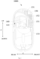
Fig. 3 is a sectional view of an earphone box according to an embodiment of the present invention. -
Fig. 4 is another sectional view of an earphone box according to an embodiment of the present invention. -
earphone box 1000,box body 1001,box cover 1002, accommodatinggroove 100, leftaccommodating groove 110, first inclined face 111, rightaccommodating groove 120, secondinclined face 121,interface 130,left interface 131,right interface 132,spring pin 133,lower mounting cavity 140,Hall sensor 141,second attraction magnet 152,upper mounting cavity 150,Hall magnet 151,first attraction magnet 152,box magnet 200,first box magnet 210,outer surface 211 of the first box magnet,second box magnet 220,outer surface 221 of the second box magnet,earphone 300,earphone magnet 310. - Embodiments of the present invention are described in detail below, and examples of the described embodiments are illustrated in accompanying drawings. The following embodiments described with reference to the accompanying drawings are exemplary and are intended to explain the present invention, rather than limit the present invention.
- The earphone box in the related art has the disadvantages of a low utilization rate of an internal space, a large overall volume and inconvenient carrying, and it is inconvenient to take the earphone out of the earphone box.
- An
earphone box 1000 according to embodiments of the present invention is described below with reference to the accompanying drawings. - As illustrated in
Figs. 1 to 4 , theearphone box 1000 according to embodiments of the present invention includes abox body 1001 and abox magnet 200. - The
box body 1001 defines anaccommodating groove 100 for accommodating anearphone 300, and theaccommodating groove 100 is provided with aninterface 130 electrically coupled to theearphone 300. - The
box magnet 200 is mounted on thebox body 1001, and is configured as a multipole magnet. Thebox magnet 200 is a planar multipole magnet, i.e., an attraction face of thebox magnet 200 has at least one pair of poles (one N pole and one S pole). Theearphone 300 is provided with anearphone magnet 310 with the same number of poles as thebox magnet 200. Therefore, an attraction face of theearphone magnet 310 also has at least one pair of poles. Moreover, a number of poles of theearphone magnet 310 and a number of poles of thebox magnet 200 are the same. That is, when thebox magnet 200 is a four-pole magnet, theearphone magnet 310 is also a four-pole magnet; when thebox magnet 200 is a two-pole magnet, theearphone magnet 310 is also a two-pole magnet. Theearphone magnet 310 attracts and couples with thebox magnet 200, so that theearphone 300 can be fixed in theaccommodating groove 100 and arranged obliquely relative to thebox body 1001, e.g., obliquely relative to a plane defined by the left-right direction and by the front-rear direction of theearphone box 1000, and/or obliquely relative to a plane defined by the up-down direction and by the front-rear direction of theearphone box 1000. - An earphone box in the related art has following disadvantages: a low utilization rate of an internal space, a large overall volume and the inconvenient carrying, and the earphone is inconvenient to take out of the earphone box.
- In the
earphone box 1000 according to embodiments of the present invention, since thebox body 1001 is provided with thebox magnet 200 configured as the multipole magnet and theearphone 300 is provided with theearphone magnet 310 with the same number of poles as thebox magnet 200, the attraction face of thebox magnet 200 has at least one pair of poles, and the attraction face of theearphone magnet 310 also has at least one pair of poles. Moreover, theearphone magnet 310 attracts and couples with thebox magnet 200, so that a plurality of poles on the attraction face of theearphone magnet 310 and a plurality of poles on the attraction face of thebox magnet 200 can attract each other together in a one-to-one correspondence, thereby realizing a multi-point positioning (at least two-point positioning) of theearphone 300 and theaccommodating groove 100, so that the positioning effect between theearphone magnet 310 and thebox magnet 200 is better or improved over conventional approaches. Moreover, theearphone magnet 310 and thebox magnet 200 are the multipole magnet, thereby increasing an attraction force between theearphone magnet 310 and thebox magnet 200, so that the positioning effect between theearphone magnet 310 and thebox magnet 200 is further improved. - The
box magnet 200 is mounted on thebox body 1001, and theearphone magnet 310 is arranged on theearphone 300. Therefore, the positioning between theearphone 300 andbox body 1001 changes from the traditional single-point positioning to the multi-point positioning (at least two-point positioning) through a multi-point attraction cooperation between theearphone magnet 310 and thebox magnet 200, thus increasing the positioning effect between theearphone 300 and thebox body 1001, so that theearphone 300 is more stable and not easy to change its position when it is attracted on thebox body 1001. Thus, theearphone 300 is more stable when charging in thebox body 1001, and the charging effect is better or improved over conventional approaches. - The improved positioning effect between the
earphone 300 and thebox body 1001 can avoid the charging instability of theearphone 300 caused by the gravity. Thus, a placement mode of theearphone 300 does not have to be limited to a mode of a horizontal placement and a mode of a vertical placement, so that theearphone 300 can be fixed in theaccommodating groove 100 conveniently and arranged obliquely relative to thebox body 1001. Since the earphone has a generally strip structure, the mode of the horizontal placement will waste space and increase a length of the box body, the mode of the vertical placement will also waste space and increase a height of the box body. The increase in each of the length, the width and the height of the box body will increase a volume of the box body. However, when theearphone 300 is arranged obliquely relative to thebox body 1001, a space of thebox body 1001 can be fully used, i.e., the space utilization rate of thebox body 1001 is improved, thereby reducing the length or the height of thebox body 1001, which is conducive to reducing the volume of thebox body 1001, i.e., a volume of theearphone box 1000 becomes small and easy to carry. - Therefore, the
earphone box 1000 according to embodiments of the present invention, when compared to conventional approaches, has the advantages of providing the improved positioning effect, the stable charging, the small volume and the good or improved portability. - For convenience of understanding, an up-down direction of the
earphone box 1000 according to embodiments of the present invention is illustrated by an arrow A inFig. 1 , a left-right direction of theearphone box 1000 according to embodiments of the present invention is illustrated by an arrow B inFig. 2 , and a front-rear direction of theearphone box 1000 according to embodiments of the present invention is illustrated by an arrow C inFig. 2 . - As illustrated in
Figs. 1 to 4 , theearphone box 1000 according to embodiments of the present invention includes thebox body 1001, thebox cover 1002 and thebox magnet 200. - As illustrated in
Fig. 1 , thebox body 1001 defines theaccommodating groove 100 for accommodating theearphone 300, and theaccommodating groove 100 is provided with theinterface 130 electrically coupled to theearphone 300. That is, theearphone 300 can be placed in theaccommodating groove 100 and electrically coupled to theinterface 130, to charge theearphone 300. - The
box cover 1002 is pivotally coupled to thebox body 1001, to open and close theaccommodating groove 100. That is, thebox cover 1002 and thebox body 1001 can rotate with respect to each other. For example, thebox body 1001 is located below thebox cover 1002 in the up-down direction. A rear end of thebox body 1001 is coupled to a rear end of thebox cover 1002. Therefore, when a front end of thebox cover 1002 rotates upward around a joint between thebox cover 1002 and thebox body 1001, theaccommodating groove 100 can be opened and theearphone 300 can be put in or taken out. When the front end of thebox cover 1002 rotates downward around the joint between thebox cover 1002 and thebox body 1001, theaccommodating groove 100 can be closed. - The
box magnet 200 is mounted on thebox body 1001, and is configured as the multipole magnet. Theearphone 300 is provided with theearphone magnet 310 with the same number of poles as thebox magnet 200. Thus, theearphone 300 can be fixed on thebox body 1001 by the multi-point positioning conveniently. - In some embodiments, each of the
box magnet 200 and theearphone magnet 310 is a two-pole magnet. The two-pole magnet has a small volume, is convenient to mount and reduces the volume of thebox body 1001. Moreover, the two-point positioning between thebox magnet 200 and theearphone magnet 310 can be realized by the two-pole magnet, to improve the positioning effect between theearphone 300 and thebox body 1001. Specifically, two poles on the attraction face of theearphone magnet 310 of the two-pole magnet and two poles on the attraction face of thebox magnet 200 of the two-pole magnet can attract each other together correspondingly, to realize the two-point positioning effect, so that the positioning effect between theearphone magnet 310 and thebox magnet 200 is good or improved. Moreover, theearphone magnet 310 and thebox magnet 200 are two-pole magnets, to increase the attraction force between theearphone magnet 310 and thebox magnet 200, so that the positioning effect between theearphone magnet 310 and thebox magnet 200 is further improved. That is, the positioning effect between theearphone 300 and thebox body 1001 is improved, so that theearphone 300 is more stable and not easy to change its position when it is attracted on thebox body 1001. Thus, theearphone 300 is more stable when charging in thebox body 1001, and the charging effect is good or improved. - The
earphone magnet 310 of the two-pole magnet and thebox magnet 200 of the two-pole magnet have a strong attraction force and a good positioning effect, so that the movement and a charging instability of theearphone 300 caused by the gravity can be avoided. Thus the placement mode of theearphone 300 does not have to be limited to the mode of the horizontal placement and the mode of the vertical placement, so that theearphone 300 can be fixed in theaccommodating groove 100 conveniently and arranged obliquely relative to thebox body 1001. - In some embodiments, the
accommodating groove 100 includes a leftaccommodating groove 110 for accommodating a left earphone and a rightaccommodating groove 120 for accommodating a right earphone. Specifically, the leftaccommodating groove 110 is located at a left portion of thebox body 1001, and the rightaccommodating groove 120 is located at a right portion of thebox body 1001. The leftaccommodating groove 110 and the rightaccommodating groove 120 are arranged symmetrically in a mirrored manner in the left-right direction, to effectively use the space of thebox body 1001, improve the space utilization rate of thebox body 1001, which is conducive to reducing the volume of thebox body 1001, so that theearphone box 1000 has a small volume and is easy to carry. - As illustrated in
Fig. 2 andFig. 3 , in some embodiments, thebox magnet 200 includes afirst box magnet 210 and asecond box magnet 220 arranged in thebox body 1001. At least part of thefirst box magnet 210 is exposed in the leftaccommodating groove 110, and at least part of thesecond box magnet 220 is exposed in the rightaccommodating groove 120. An exposed face (an attraction face) of at least a part of thefirst box magnet 210 has a plurality of poles, and an exposed face (the attraction face) of at least a part of thesecond box magnet 220 has a plurality of poles. - The exposed face of the
first box magnet 210 can directly attract theearphone magnet 310 of the left earphone in the leftaccommodating groove 110 and has a plurality of positioning points (at least two), and thefirst box magnet 210 can be in direct contact with theearphone magnet 310 of the left earphone in the leftaccommodating groove 110 without a barrier layer, so that the attraction effect between thefirst box magnet 210 and theearphone magnet 310 of the left earphone in the leftaccommodating groove 110 can be improved. That is, the left earphone is fixed more stably, and the charging is stable. - Similarly, the exposed face of the
second box magnet 220 can directly attract theearphone magnet 310 of the right earphone in the rightaccommodating groove 120 and has a plurality of positioning points (at least two), and thesecond box magnet 220 can be in direct contact with theearphone magnet 310 of the right earphone in the rightaccommodating groove 120 without the barrier layer, so that the attraction effect between thesecond box magnet 220 and the right earphone in the rightaccommodating groove 120 is improved. That is, the right earphone is fixed more stably, and the charging is stable. - As illustrated in
Fig. 3 , in some embodiments, thebox body 1001 includes a first inclined face 111 constituting at least part of a side wall of the leftaccommodating groove 110 and a secondinclined face 121 constituting at least part of a side wall of the rightaccommodating groove 120. The first inclined face 111 can allow the left earphone to be placed obliquely in the leftaccommodating groove 110, and the secondinclined face 121 can allow the right earphone to be placed obliquely in the rightaccommodating groove 120, to improve the utilization rate of the space of thebox body 1001, which is conducive to reducing the volume of thebox body 1001, so thatbox body 1001 is easy to carry. - The
first box magnet 210 is arranged on the first inclined face 111 with anouter surface 211 of thefirst box magnet 210 being flush with the first inclined face 111. That is, the outer surface 211 (the attraction face) of thefirst box magnet 210 and the first inclined face 111 are on the same plane, so that the left earphone can be placed and positioned in the leftaccommodating groove 110 conveniently. Thesecond box magnet 220 is arranged on the secondinclined face 121 with anouter surface 221 of thesecond box magnet 220 being flush with the secondinclined face 121. That is, the outer surface 221 (the attraction face) of thesecond box magnet 220 and the secondinclined face 121 are on the same plane, so that the right earphone can be placed and positioned in the rightaccommodating groove 120 conveniently. - In some embodiments, a polarity distribution at the
outer surface 211 of thefirst box magnet 210 is different from a polarity distribution at theouter surface 221 of thesecond box magnet 220. For example, when an upper portion of theouter surface 211 of thefirst box magnet 210 is N pole and an lower portion thereof is S pole, an upper portion of theouter surface 221 of thesecond box magnet 220 is S pole and an lower portion thereof is N pole, or, when a left portion of theouter surface 211 of thefirst box magnet 210 is N pole and a right portion thereof is S pole, a left portion of theouter surface 221 of thesecond box magnet 220 is S pole and a right portion thereof is N pole. Thus, it is difficult to place the left earphone in the rightaccommodating groove 120 or to place the right earphone in the leftaccommodating groove 110, thereby facilitating the correct positioning and the placement of the left earphone and the right earphone. - As illustrated in
Fig. 2 andFig. 3 , in some embodiments, theinterface 130 includes aleft interface 131 arranged in the leftaccommodating groove 110 and aright interface 132 arranged in the rightaccommodating groove 120. Theleft interface 131 may be electrically coupled to the left earphone, to charge the left earphone, and theright interface 132 may be electrically coupled to the right earphone, to charge the right earphone. - An axis perpendicular to a surface of the left interface 131 (also referred to as the axis of the left interface 131) and an axis perpendicular to a surface of the right interface 132 (also referred to as the axis of the right interface 132) are arranged obliquely. That is, the axis of the
left interface 131 can be arranged obliquely relative to the up-down direction. For example, the axis of theleft interface 131 can be substantially perpendicular to the first inclined face 111, to facilitate an electrical coupling between the left earphone and theleft interface 131, i.e., to facilitate theleft interface 131 to stably charge the left earphone. The axis of theright interface 132 can be arranged obliquely relative to the up-down direction, and the axis of theright interface 132 can be substantially perpendicular to the secondinclined face 121, to facilitate an electrical coupling between the right earphone and theright interface 132, i.e., to facilitate theright interface 132 to stably charge the right earphone. - In some embodiments, an angle included between the axis of each of the
left interface 131 and theright interface 132 and a plane defined by the left-right direction and by the front-rear direction of the earphone box 1000 (e.g., the horizontal plane when the earphone box is positioned as illustrated in the figures) is 45°-55°. In this angle range, thebox body 1001 has a smaller volume and is easy to carry while facilitating theleft interface 131/theright interface 132 to stably charge the left earphone/the right earphone. - As illustrated in
Fig. 2 andFig. 3 , in some embodiments, theleft interface 131 is arranged on the first inclined face 111 and adjacent to thefirst box magnet 210. Therefore, after the left earphone enters into the leftaccommodating groove 110, it can be electrically coupled to theleft interface 131 conveniently. Moreover, a position between thefirst box magnet 210 of the left earphone and theearphone magnet 310 of the left earphone has a strong attraction force, thus realizing the good positioning effect. Theleft interface 131 is adjacent to thefirst box magnet 210, so that the left earphone and theleft interface 131 are coupled stably, i.e., the charging of the left earphone is more stable. - The
right interface 132 is arranged on the secondinclined face 121 and adjacent to thesecond box magnet 220. Therefore, after the right earphone enters into the rightaccommodating groove 120, it can be electrically coupled to theright interface 132 conveniently. Moreover, a position between thesecond box magnet 220 of the right earphone and theearphone magnet 310 of the right earphone has a strong attraction force, thus realizing the good positioning effect. Theright interface 132 is adjacent to thesecond box magnet 220, so that the right earphone and theright interface 132 are coupled stably, i.e., the charging of the right earphone is more stable. - As illustrated in
Fig. 2 andFig. 3 , in some embodiments, each of theleft interface 131 and theright interface 132 is a pogopin, and the left earphone and the right earphone are each provided with a coupling copper column for abutting with aspring pin 133 of pogopin. For example, in each of theleft interface 131 and theright interface 132, twospring pins 133 of pogopin are provided, and located at two sides of thebox magnet 200. That is, theleft interface 131 includes twospring pins 133 of pogopin, and the twospring pins 133 of pogopin of theleft interface 131 are located at two opposite sides of thefirst box magnet 210; and theright interface 132 includes twospring pins 133 of pogopin, and the twospring pins 133 of pogopin of theright interface 132 are located at two opposite sides of thesecond box magnet 220. When the left earphone is placed in the leftaccommodating groove 110, the coupling copper columns of the left earphone press the spring pins 133 of theleft interface 131, to create the electrical coupling between the left earphone and theleft interface 131, so that the charging of the left earphone is stable. When the right earphone is placed in the rightaccommodating groove 120, the coupling copper columns of the right earphone press the spring pins 133 of theright interface 132, to create the electrical coupling between the right earphone and theright interface 132, so that the charging of the right earphone is stable. - In some embodiments, each of the first inclined face 111 and the second
inclined face 121 is a frosted face. Therefore, when the left earphone is placed on the first inclined face 111, a friction is large, so that the left earphone is not easy to move and the positioning effect is good. When the right earphone is placed on the secondinclined face 121, a friction is large, so that the right earphone is not easy to move and the positioning effect is good. Thefirst box magnet 210 and theleft interface 131 are arranged on the first inclined face 111 with the frosted face, so that the left earphone can be fixed and electrically coupled only by contacting the first inclined face 111. Thus, the left earphone can be arranged obliquely, maximizing utilization rate of the space of thebox body 1001 and reducing the volume of thebox body 1001. Moreover, the leftaccommodating groove 110 does not have to be limited to the profile of the earphone thereby realizing the reliability of charging also when the earphone is fitted with different shapes of different specifications of ear caps or sleeves. Thesecond box magnet 220 and theright interface 132 are arranged on the secondinclined face 121 with the frosted face, so that the right earphone can be fixed and electrically coupled only by contacting the secondinclined face 121. Thus, the right earphone can be arranged obliquely, maximizing utilization rate of the space of thebox body 1001 and reducing the volume of thebox body 1001. Moreover, the rightaccommodating groove 120 does not have be limited to the profile of the earphone thereby realizing the reliability of charging also when the earphone is fitted with different shapes of different specifications of ear caps or sleeves. - As illustrated in
Fig. 3 , in some embodiments, the first inclined face 111 is inclined towards the rightaccommodating groove 120, so that the left earphone accommodated in the leftaccommodating groove 110 faces towards the rightaccommodating groove 120. The secondinclined face 121 is inclined towards the leftaccommodating groove 110, so that the right earphone accommodated in the rightaccommodating groove 120 is inclined towards the leftaccommodating groove 110. Thus, positions of thefirst box magnet 210 and theleft interface 131 and positions of thesecond box magnet 220 and theright interface 132 are close, and all accommodated in a space, to make full use of the space of thebox body 1001 and reduce the volume of thebox body 1001. - As illustrated in
Fig. 3 andFig. 4 , in some embodiments, thebox body 1001 further includes alower mounting cavity 140 spaced apart from theaccommodating groove 100, thebox cover 1002 defines an upper mountingcavity 150, thelower mounting cavity 140 is provided with aHall sensor 141, and the upper mountingcavity 150 is provided with aHall magnet 151. Specifically, thelower mounting cavity 140 is located below theaccommodating groove 100, and the upper mountingcavity 150 is located above theaccommodating groove 100. TheHall sensor 141 in thelower mounting cavity 140 can cooperate with theHall magnet 151 in the upper mountingcavity 150 using the Hall effect. When thebox cover 1002 is opened, i.e., when theaccommodating groove 100 is opened, theHall sensor 141 detects information and sends the information to theearphone 300, so that a Bluetooth of theearphone 300 is turned on and theearphone 300 is automatically paired with the mobile phone. - In some embodiments, the upper mounting
cavity 150 is provided with afirst attraction magnet 152, thelower mounting cavity 140 is provided with a second attraction magnet 142, and the second attraction magnet 142 is configured to attract and couple with thefirst attraction magnet 152 when thebox cover 1002 closes the accommodating groove. Thus, when thebox cover 1002 is closed, a coupling between thebox body 1001 and thebox cover 1002 is strengthened, thus preventing thebox cover 1002 from being opened by mistake and preventing theearphone 300 from being lost. - The
earphone 300 according to embodiments of the present invention includes anearphone body 310 configured as a bud shape, and theearphone body 310 is adapted to fit in theaccommodating groove 100 of theearphone box 1000 according to any one of the above embodiments. - The
earphone 300 according to embodiments of the present invention can be obliquely placed in theaccommodating groove 100 in theearphone box 1000, has a good positioning effect and can be charged stably. Moreover, after theearphone 300 is placed in theaccommodating groove 100, the overall volume is small and theearphone 300 is easy to carry. - In some embodiments, the
earphone 300 further includes a plurality of earphone caps orsleeves 320 of different specifications. Each of the plurality ofearphone sleeves 320 is adapted to be fitted over theearphone body 310, and theearphone body 310 fitted with anyearphone sleeve 320 can fit in theaccommodating groove 100. - That is, a space of the
accommodating groove 100 is larger than a total volume of theearphone body 310 and theearphone sleeve 320 fitted over a side of theearphone body 310. Theearphone 300 can be put into theaccommodating groove 100 for charging and storage without removing theearphone sleeve 320. Theearphone box 1000 has a strong adaptability. - A 1st embodiment provides an earphone box (1000), comprising:
- a box body (1001) defining an accommodating groove (100) configured to accommodate an earphone (300), the accommodating groove (100) being provided with an interface (130) configured to be electrically coupled to the earphone (300);
- a box magnet (200) mounted on the box body (1001) and configured as a multipole magnet, the box magnet (200) is configured to attract and couple with an earphone magnet (310) of the earphone (300) which has the same number of poles as the box magnet (200), and an attraction face (211, 221) of the box magnet (200) being an inclined face.
- A 2nd embodiment provides the earphone box (1000) according to the 1st embodiment, wherein each of the box magnet (200) and the earphone magnet (310) is a two-pole magnet.
- A 3rd embodiment provides the earphone box (1000) according to the 1st embodiment or the 2nd embodiment, wherein
- the accommodating groove (100) comprises a left accommodating groove (110) configured to accommodate a left earphone and a right accommodating groove (120) configured to accommodate a right earphone,
- the box magnet (200) comprises a first box magnet (210) and a second box magnet (220) arranged in the box body (1001),
- the first box magnet (210) is configured to attract and couple with the earphone magnet (310) of the left earphone, and
- the second box magnet (220) is configured to attract and couple with the earphone magnet (310) of the right earphone.
- A 4th embodiment provides the earphone box (1000) according to the 3rd embodiment, wherein
- the left accommodating groove (110) is located at a left portion of the box body (1001), and
- the right accommodating groove (120) is located at a right portion of the box body (1001),
- the left accommodating groove (110) and the right accommodating groove (120) are arranged symmetrically in a mirrored manner in a left-right direction (B).
- A 5th embodiment provides the earphone box (1000) according to the 3rf embodiment or the 4th embodiment, wherein
- the box body (1001) comprises a first inclined face (111) constituting at least part of a side wall of the left accommodating groove (110) and a second inclined face (121) constituting at least part of a side wall of the right accommodating groove (120),
- the first box magnet (210) is arranged on the first inclined face (111) with an outer surface (211) of the first box magnet (210) being flush with the first inclined face (111), and
- the second box magnet (220) is arranged on the second inclined face (121) with an outer surface (221) of the second box magnet (220) being flush with the second inclined face (121).
- A 6th embodiment provides the earphone box (1000) according to any one of the 3rd to 5th embodiments, wherein a polarity distribution at an outer surface (211) of the first box magnet (210) is different from a polarity distribution at the outer surface (221) of the second box magnet (220).
- A 7th embodiment provides the earphone box (1000) according to the 6th embodiment, wherein
- poles of the first box magnet (210) are opposite to each other,
- poles of the second box magnet (210) are opposite to each other, and
- the poles of the first box magnet (210) are opposite to corresponding poles of the second box magnet (220) in position.
- An 8th embodiment provides the earphone box (1000) according to any one of the 3rd to 7th embodiments, wherein
- the interface (130) comprises a left interface (131) arranged in the left accommodating groove (110) and a right interface (132) arranged in the right accommodating groove (120), and
- an axis of the left interface (131) and an axis of the right interface (132) are arranged obliquely.
- A 9th embodiment provides the earphone box (1000) according to the 8th embodiment, wherein an angle included between the axis of each of the left interface (131) and the right interface (132) and a horizontal plane is 45°-55°.
- A 10th embodiment provides the earphone box (1000) according to any one of the 5th to 9th embodiments, wherein each of the first inclined face (111) and the second inclined face (121) is a frosted face.
- An 11th embodiment provides the earphone box (1000) according to any one of the 1st to 10th embodiments, wherein
- the earphone box (1000) further comprises a box cover (1002) coupled to the box body (1001),
- the box body (1001) further comprises a lower mounting cavity (140) separated from the accommodating groove (100),
- the box cover (1002) defines an upper mounting cavity (150),
- the lower mounting cavity (140) is provided with a Hall sensor (141), and the upper mounting cavity (150) is provided with a Hall magnet (151).
- A 12th embodiment provides the earphone box (1000) according to the 11th embodiment, wherein
- the upper mounting cavity (150) is provided with a first attraction magnet (152),
- the lower mounting cavity (140) is provided with a second attraction magnet (142), and
- the second attraction magnet (142) is configured to attract and couple with the first attraction magnet (152) when the box cover (1002) closes the accommodating groove (100).
- A 13th embodiment provides the earphone box (1000) according to any one of the 1st to 12th embodiments, wherein
the interface (130) is provided with a pogopin having two spring pins (133), and the box magnet (200) is arranged between the two spring pins (133) of the pogopin. - A 14th embodiment provides the earphone (300), comprising an earphone body (310) configured as a bud shape, the earphone body (310) being adapted to fit in an accommodating groove (100) of an earphone box (1000) according to any one of the 1st to 13th embodiments.
- A 15th embodiment provides the earphone (300) according to the 14th embodiment, wherein
- the earphone (300) further comprises a plurality of earphone sleeves (320) of different specifications,
- each of the plurality of earphone sleeves (320) is adapted to be fitted over the earphone body (310), and
- the earphone body (310) fitted with any earphone sleeve (320) is configured to match in the accommodating groove (100).
- In the description of the present invention, it shall be understood that terms such as "central," "longitudinal," "transverse," "length," "width," "thickness," "upper," "lower," "front," "rear," "left," "right," "vertical," "horizontal," "top," "bottom," "inner," "outer," "clockwise," "counterclockwise," "axial," "radial" and "circumferential" should be construed to refer to the orientation as then described or as illustrated in the drawings under discussion. These relative terms are for convenience of description and do not indicate or imply that the device or element referred to must have a particular orientation, or be constructed and operated in a particular orientation. Thus, these terms shall not be construed as limitation on the present invention.
- In addition, terms such as "first" and "second" are merely used for descriptive purposes and cannot be understood as indicating or implying relative importance or the number of technical features indicated. Thus, the features associated with "first" and "second" may explicitly or implicitly include at least one of the features. In the description of the present invention, unless otherwise specifically defined, "a plurality of" means at least two, such as two, three, etc.
- In the present invention, unless otherwise explicitly specified and defined, the terms "mounted," "connected," "coupled," "fixed" and the like are used broadly, and may be, for example, fixed couplings, detachable couplings, or integral couplings; may also be mechanical or electrical couplings or intercommunication; may also be direct couplings or indirect couplings via intervening structures; may also be inner communications or interactions of two elements, which can be understood by those skilled in the art according to specific situations.
- In the present invention, unless otherwise explicitly specified and defined, a structure in which a first feature is "on" or "below" a second feature may include an embodiment in which the first feature is in direct contact with the second feature, and may also include an embodiment in which the first feature and the second feature are not in direct contact with each other, but are contacted via an additional feature formed therebetween. Furthermore, a first feature "on," "above," or "on top of" a second feature may include an embodiment in which the first feature is right or obliquely "on," "above," or "on top of" the second feature, or just means that the first feature is at a height higher than that of the second feature; while a first feature "below," "under," or "on bottom of" a second feature may include an embodiment in which the first feature is right or obliquely "below," "under," or "on bottom of" the second feature, or just means that the first feature is at a height lower than that of the second feature.
- In the present invention, terms such as "an embodiment," "some embodiments," "an example," "a specific example," or "some examples," means that a particular feature, structure, material, or characteristic described in coupling with embodiment or example is included in at least one embodiment or example of the present invention. Thus, the appearances of these terms in various places throughout this specification are not necessarily referring to the same embodiment or example of the present invention. Furthermore, the particular features, structures, materials, or characteristics may be combined in any suitable manner in one or more embodiments or examples. In addition, without contradiction, those skilled in the art may combine and unite different embodiments or examples or features of the different embodiments or examples described in this specification.
Claims (15)
- An earphone box assembly, comprising:an earphone (300), comprising an earphone body (310); andan earphone box (1000), comprising:a box body (1001) defining an accommodating groove (100) configured to accommodate an earphone (300), the accommodating groove (100) being provided with an interface (130) configured to be electrically coupled to the earphone (300); anda box magnet (200) mounted on the box body (1001) and configured as a multipole magnet;wherein the earphone (300) comprises an earphone magnet (310) which has the same number of poles as the box magnet (200), and the box magnet (200) is configured to attract and couple with the earphone magnet (310); andan attraction face (211, 221) of the box magnet (200) is an inclined face allowing the earphone (300) to be placed in the accommodating groove (100) spaced apart from a bottom of the accommodating groove (100).
- The earphone box assembly according to claim 1, wherein each of the box magnet (200) and the earphone magnet (310) is a two-pole magnet.
- The earphone box assembly according to claim 1 or 2, whereinthe accommodating groove (100) comprises a left accommodating groove (110) configured to accommodate a left earphone and a right accommodating groove (120) configured to accommodate a right earphone,the box magnet (200) comprises a first box magnet (210) and a second box magnet (220) arranged in the box body (1001),the first box magnet (210) is configured to attract and couple with the earphone magnet (310) of the left earphone, andthe second box magnet (220) is configured to attract and couple with the earphone magnet (310) of the right earphone.
- The earphone box assembly according to claim 3, whereinthe left accommodating groove (110) is located at a left portion of the box body (1001), andthe right accommodating groove (120) is located at a right portion of the box body (1001),the left accommodating groove (110) and the right accommodating groove (120) are arranged symmetrically in a mirrored manner in a left-right direction (B).
- The earphone box assembly according to claim 3 or 4, whereinthe box body (1001) comprises a first inclined face (111) constituting at least part of a side wall of the left accommodating groove (110) and a second inclined face (121) constituting at least part of a side wall of the right accommodating groove (120),the first box magnet (210) is arranged on the first inclined face (111) with an outer surface (211) of the first box magnet (210) being flush with the first inclined face (111), andthe second box magnet (220) is arranged on the second inclined face (121) with an outer surface (221) of the second box magnet (220) being flush with the second inclined face (121).
- The earphone box assembly according to any one of claims 3 to 5, wherein a polarity distribution at an outer surface (211) of the first box magnet (210) is different from a polarity distribution at the outer surface (221) of the second box magnet (220).
- The earphone box assembly according to claim 6, whereinpoles of the first box magnet (210) are opposite to each other,poles of the second box magnet (210) are opposite to each other, andthe poles of the first box magnet (210) are opposite to corresponding poles of the second box magnet (220) in position.
- The earphone box assembly according to any one of claims 3 to 7, whereinthe interface (130) comprises a left interface (131) arranged in the left accommodating groove (110) and a right interface (132) arranged in the right accommodating groove (120), andan axis of the left interface (131) and an axis of the right interface (132) are arranged obliquely.
- The earphone box assembly according to claim 8, wherein an angle included between the axis of each of the left interface (131) and the right interface (132) and a horizontal plane is 45° -55°.
- The earphone box assembly according to any one of claims 5 to 9, wherein each of the first inclined face (111) and the second inclined face (121) is a frosted face.
- The earphone box assembly according to any one of claims 1 to 10, whereinthe earphone box (1000) further comprises a box cover (1002) coupled to the box body (1001),the box body (1001) further comprises a lower mounting cavity (140) separated from the accommodating groove (100),the box cover (1002) defines an upper mounting cavity (150),the lower mounting cavity (140) is provided with a Hall sensor (141), and the upper mounting cavity (150) is provided with a magnet (151) cooperating with the Hall sensor (141) using the Hall effect.
- The earphone box assembly according to claim 11, whereinthe upper mounting cavity (150) is provided with a first attraction magnet (152),the lower mounting cavity (140) is provided with a second attraction magnet (142), and the second attraction magnet (142) is configured to attract and couple with the first attraction magnet (152) when the box cover (1002) closes the accommodating groove (100).
- The earphone box assembly according to any one of claims 1 to 12, whereinthe interface (130) is provided with a pogopin having two spring pins (133), andthe box magnet (200) is arranged between the two spring pins (133) of the pogopin.
- The earphone box assembly according to any one of claims 5 to 7, wherein the interface comprises a left interface (131) arranged in the left accommodating groove (110) and a right interface (132) arranged in the right accommodating groove (120), an axis of the left interface (131) is perpendicular to the first inclined face (111), and an axis of the right interface (132) is perpendicular to the second inclined face (121).
- The earphone box assembly according to claim 14, wherein the left interface (131) is arranged on the first inclined face (111) and adjacent to the first box magnet (210), and the right interface (132) is arranged on the second inclined face (121) and adjacent to the second box magnet (220).
Applications Claiming Priority (2)
| Application Number | Priority Date | Filing Date | Title |
|---|---|---|---|
| CN202111045769.1A CN115776627A (en) | 2021-09-07 | 2021-09-07 | Earphone box and earphone |
| EP22158880.9A EP4145850B1 (en) | 2021-09-07 | 2022-02-25 | Earphone box and earphone |
Related Parent Applications (2)
| Application Number | Title | Priority Date | Filing Date |
|---|---|---|---|
| EP22158880.9A Division EP4145850B1 (en) | 2021-09-07 | 2022-02-25 | Earphone box and earphone |
| EP22158880.9A Division-Into EP4145850B1 (en) | 2021-09-07 | 2022-02-25 | Earphone box and earphone |
Publications (2)
| Publication Number | Publication Date |
|---|---|
| EP4468738A2 true EP4468738A2 (en) | 2024-11-27 |
| EP4468738A3 EP4468738A3 (en) | 2025-02-26 |
Family
ID=80461668
Family Applications (2)
| Application Number | Title | Priority Date | Filing Date |
|---|---|---|---|
| EP24206115.8A Pending EP4468738A3 (en) | 2021-09-07 | 2022-02-25 | Earphone box and earphone |
| EP22158880.9A Active EP4145850B1 (en) | 2021-09-07 | 2022-02-25 | Earphone box and earphone |
Family Applications After (1)
| Application Number | Title | Priority Date | Filing Date |
|---|---|---|---|
| EP22158880.9A Active EP4145850B1 (en) | 2021-09-07 | 2022-02-25 | Earphone box and earphone |
Country Status (3)
| Country | Link |
|---|---|
| US (1) | US11979702B2 (en) |
| EP (2) | EP4468738A3 (en) |
| CN (1) | CN115776627A (en) |
Families Citing this family (17)
| Publication number | Priority date | Publication date | Assignee | Title |
|---|---|---|---|---|
| USD991915S1 (en) * | 2021-03-16 | 2023-07-11 | Beijing Xiaomi Mobile Software Co., Ltd. | Earphone |
| JP1742865S (en) * | 2021-07-30 | 2023-04-25 | earphone case | |
| USD1012905S1 (en) * | 2021-09-24 | 2024-01-30 | Guangdong Xizhongxi Technology Co., Ltd. | Set of wireless earphones and charging case |
| USD1003043S1 (en) * | 2021-09-30 | 2023-10-31 | Shenzhen Earfun Technology Co., Ltd. | Headset case |
| US12100982B2 (en) * | 2021-10-29 | 2024-09-24 | Nucurrent, Inc. | Wireless power transfer system for listening devices |
| US12100983B2 (en) | 2021-10-29 | 2024-09-24 | Nucurrent, Inc. | Wireless power transfer system for listening devices with expandable case |
| USD1025020S1 (en) * | 2022-03-04 | 2024-04-30 | Google Llc | Earbud cap |
| JP1742627S (en) * | 2022-05-07 | 2023-04-21 | earphone case | |
| USD1080530S1 (en) * | 2022-06-02 | 2025-06-24 | Beijing Xiaomi Mobile Software Co., Ltd | Charging case for earphones |
| USD1077741S1 (en) * | 2022-09-26 | 2025-06-03 | Bose Corporation | Charging case |
| USD1061433S1 (en) * | 2022-09-26 | 2025-02-11 | Bose Corporation | Charging case |
| USD1068738S1 (en) * | 2022-12-01 | 2025-04-01 | Dongguan Iglory Co., Ltd. | Earphones and case |
| USD1065154S1 (en) * | 2023-03-27 | 2025-03-04 | Yun Deng | Earphone case and earphones |
| JP1760720S (en) * | 2023-03-31 | 2024-01-05 | Charging case for earphones | |
| CN116437254A (en) * | 2023-04-06 | 2023-07-14 | 广东鸣洋智能科技有限公司 | An independently detachable earphone charging box |
| JP1794824S (en) * | 2024-09-02 | 2025-04-01 | Earphone Charger | |
| USD1117034S1 (en) * | 2024-09-03 | 2026-03-10 | Shenzhen Zhichuang A11 Technology Co., Ltd. | Earphones with charging case |
Family Cites Families (9)
| Publication number | Priority date | Publication date | Assignee | Title |
|---|---|---|---|---|
| EP3541092B1 (en) * | 2015-09-30 | 2021-08-11 | Apple Inc. | Earbud case with charging system |
| CN107809696B (en) | 2017-11-30 | 2019-12-20 | 成都必盛科技有限公司 | Wireless earphone capable of establishing interaction with earphone box |
| US20200107106A1 (en) * | 2018-09-28 | 2020-04-02 | Apple Inc. | Hybrid retention and sensor shunt for wireless listening devices |
| US10866290B2 (en) * | 2019-01-17 | 2020-12-15 | Google Llc | Magnetic sensing device for lid |
| CN210431797U (en) * | 2019-09-27 | 2020-04-28 | 潍坊歌尔电子有限公司 | Wireless earphone adsorption and on-site detection device |
| CN210670516U (en) * | 2019-12-31 | 2020-06-02 | 东莞市誉达通信科技有限公司 | Earphone assembly, earphone and earphone box |
| CN211860506U (en) | 2020-05-15 | 2020-11-03 | 歌尔科技有限公司 | Earphone storage box |
| CN213152320U (en) | 2020-05-26 | 2021-05-07 | 深圳市冠旭电子股份有限公司 | Headphone holder and headphone charging box |
| CN213677758U (en) * | 2020-10-15 | 2021-07-13 | 广东美她实业投资有限公司 | Earphone box and earphone assembly comprising same |
-
2021
- 2021-09-07 CN CN202111045769.1A patent/CN115776627A/en active Pending
-
2022
- 2022-02-25 EP EP24206115.8A patent/EP4468738A3/en active Pending
- 2022-02-25 US US17/681,397 patent/US11979702B2/en active Active
- 2022-02-25 EP EP22158880.9A patent/EP4145850B1/en active Active
Also Published As
| Publication number | Publication date |
|---|---|
| US11979702B2 (en) | 2024-05-07 |
| EP4145850A1 (en) | 2023-03-08 |
| US20230074689A1 (en) | 2023-03-09 |
| CN115776627A (en) | 2023-03-10 |
| EP4145850B1 (en) | 2024-12-04 |
| EP4468738A3 (en) | 2025-02-26 |
Similar Documents
| Publication | Publication Date | Title |
|---|---|---|
| EP4468738A2 (en) | Earphone box and earphone | |
| US12207035B2 (en) | Earphone case and wireless earphone | |
| CN106331930A (en) | Charging box of wireless headset and wireless headset adapting to charging box | |
| US20250070504A1 (en) | Socket, plug, connector assembly, data cable, and smart glasses | |
| CN112911445A (en) | Earphone charging box and earphone device | |
| CN209949357U (en) | Wireless earphone assembly | |
| CN112653954B (en) | Charging box and earphone charging system | |
| CN214315338U (en) | Mobile phone shell | |
| JP2020087917A (en) | First connector, second connector, and electrical connector assembly | |
| KR20240002063U (en) | An automatic magnetic suction fixation sturcture for wireless charging | |
| CN216565540U (en) | Headphone Cases and Headphones | |
| US20210029475A1 (en) | Charging contact connection for a charger, mating contact connection, charging contact system and electrical device | |
| CN216700282U (en) | Charging box | |
| CN211019177U (en) | an earphone box | |
| CN209283444U (en) | Headphone charging stand | |
| CN111479187B (en) | Bracelet formula TWS device | |
| CN218122476U (en) | smart watch | |
| CN113876095B (en) | headphone box | |
| CN209517440U (en) | Wireless headset external member and charging box | |
| CN220776053U (en) | Earphone charging box | |
| CN210629800U (en) | Charging seat and earphone with same | |
| CN210518765U (en) | Novel bluetooth headset box that charges | |
| CN115499754A (en) | Wireless Bluetooth earphone | |
| WO2022160472A1 (en) | Earphone assembly | |
| CN209088567U (en) | Charging units and smart knives |
Legal Events
| Date | Code | Title | Description |
|---|---|---|---|
| PUAI | Public reference made under article 153(3) epc to a published international application that has entered the european phase |
Free format text: ORIGINAL CODE: 0009012 |
|
| STAA | Information on the status of an ep patent application or granted ep patent |
Free format text: STATUS: REQUEST FOR EXAMINATION WAS MADE |
|
| 17P | Request for examination filed |
Effective date: 20241011 |
|
| AC | Divisional application: reference to earlier application |
Ref document number: 4145850 Country of ref document: EP Kind code of ref document: P |
|
| AK | Designated contracting states |
Kind code of ref document: A2 Designated state(s): AL AT BE BG CH CY CZ DE DK EE ES FI FR GB GR HR HU IE IS IT LI LT LU LV MC MK MT NL NO PL PT RO RS SE SI SK SM TR |
|
| PUAL | Search report despatched |
Free format text: ORIGINAL CODE: 0009013 |
|
| AK | Designated contracting states |
Kind code of ref document: A3 Designated state(s): AL AT BE BG CH CY CZ DE DK EE ES FI FR GB GR HR HU IE IS IT LI LT LU LV MC MK MT NL NO PL PT RO RS SE SI SK SM TR |
|
| RIC1 | Information provided on ipc code assigned before grant |
Ipc: H04R 1/10 20060101AFI20250123BHEP |
|
| GRAP | Despatch of communication of intention to grant a patent |
Free format text: ORIGINAL CODE: EPIDOSNIGR1 |
|
| STAA | Information on the status of an ep patent application or granted ep patent |
Free format text: STATUS: GRANT OF PATENT IS INTENDED |
|
| INTG | Intention to grant announced |
Effective date: 20251215 |
|
| GRAS | Grant fee paid |
Free format text: ORIGINAL CODE: EPIDOSNIGR3 |
|
| GRAA | (expected) grant |
Free format text: ORIGINAL CODE: 0009210 |
|
| STAA | Information on the status of an ep patent application or granted ep patent |
Free format text: STATUS: THE PATENT HAS BEEN GRANTED |