EP4468463A1 - Battery pack and vehicle comprising same - Google Patents
Battery pack and vehicle comprising same Download PDFInfo
- Publication number
- EP4468463A1 EP4468463A1 EP23912448.0A EP23912448A EP4468463A1 EP 4468463 A1 EP4468463 A1 EP 4468463A1 EP 23912448 A EP23912448 A EP 23912448A EP 4468463 A1 EP4468463 A1 EP 4468463A1
- Authority
- EP
- European Patent Office
- Prior art keywords
- battery pack
- cooling
- cooling fluid
- battery
- pack according
- Prior art date
- Legal status (The legal status is an assumption and is not a legal conclusion. Google has not performed a legal analysis and makes no representation as to the accuracy of the status listed.)
- Granted
Links
Images





Classifications
-
- H—ELECTRICITY
- H01—ELECTRIC ELEMENTS
- H01M—PROCESSES OR MEANS, e.g. BATTERIES, FOR THE DIRECT CONVERSION OF CHEMICAL ENERGY INTO ELECTRICAL ENERGY
- H01M10/00—Secondary cells; Manufacture thereof
- H01M10/60—Heating or cooling; Temperature control
- H01M10/65—Means for temperature control structurally associated with the cells
- H01M10/656—Means for temperature control structurally associated with the cells characterised by the type of heat-exchange fluid
- H01M10/6567—Liquids
- H01M10/6568—Liquids characterised by flow circuits, e.g. loops, located externally to the cells or cell casings
-
- H—ELECTRICITY
- H01—ELECTRIC ELEMENTS
- H01M—PROCESSES OR MEANS, e.g. BATTERIES, FOR THE DIRECT CONVERSION OF CHEMICAL ENERGY INTO ELECTRICAL ENERGY
- H01M10/00—Secondary cells; Manufacture thereof
- H01M10/60—Heating or cooling; Temperature control
- H01M10/61—Types of temperature control
- H01M10/613—Cooling or keeping cold
-
- H—ELECTRICITY
- H01—ELECTRIC ELEMENTS
- H01M—PROCESSES OR MEANS, e.g. BATTERIES, FOR THE DIRECT CONVERSION OF CHEMICAL ENERGY INTO ELECTRICAL ENERGY
- H01M10/00—Secondary cells; Manufacture thereof
- H01M10/60—Heating or cooling; Temperature control
- H01M10/62—Heating or cooling; Temperature control specially adapted for specific applications
- H01M10/625—Vehicles
-
- H—ELECTRICITY
- H01—ELECTRIC ELEMENTS
- H01M—PROCESSES OR MEANS, e.g. BATTERIES, FOR THE DIRECT CONVERSION OF CHEMICAL ENERGY INTO ELECTRICAL ENERGY
- H01M10/00—Secondary cells; Manufacture thereof
- H01M10/60—Heating or cooling; Temperature control
- H01M10/64—Heating or cooling; Temperature control characterised by the shape of the cells
- H01M10/643—Cylindrical cells
-
- H—ELECTRICITY
- H01—ELECTRIC ELEMENTS
- H01M—PROCESSES OR MEANS, e.g. BATTERIES, FOR THE DIRECT CONVERSION OF CHEMICAL ENERGY INTO ELECTRICAL ENERGY
- H01M10/00—Secondary cells; Manufacture thereof
- H01M10/60—Heating or cooling; Temperature control
- H01M10/65—Means for temperature control structurally associated with the cells
- H01M10/655—Solid structures for heat exchange or heat conduction
- H01M10/6556—Solid parts with flow channel passages or pipes for heat exchange
-
- H—ELECTRICITY
- H01—ELECTRIC ELEMENTS
- H01M—PROCESSES OR MEANS, e.g. BATTERIES, FOR THE DIRECT CONVERSION OF CHEMICAL ENERGY INTO ELECTRICAL ENERGY
- H01M10/00—Secondary cells; Manufacture thereof
- H01M10/60—Heating or cooling; Temperature control
- H01M10/65—Means for temperature control structurally associated with the cells
- H01M10/655—Solid structures for heat exchange or heat conduction
- H01M10/6556—Solid parts with flow channel passages or pipes for heat exchange
- H01M10/6557—Solid parts with flow channel passages or pipes for heat exchange arranged between the cells
-
- H—ELECTRICITY
- H01—ELECTRIC ELEMENTS
- H01M—PROCESSES OR MEANS, e.g. BATTERIES, FOR THE DIRECT CONVERSION OF CHEMICAL ENERGY INTO ELECTRICAL ENERGY
- H01M50/00—Constructional details or processes of manufacture of the non-active parts of electrochemical cells other than fuel cells, e.g. hybrid cells
- H01M50/20—Mountings; Secondary casings or frames; Racks, modules or packs; Suspension devices; Shock absorbers; Transport or carrying devices; Holders
- H01M50/244—Secondary casings; Racks; Suspension devices; Carrying devices; Holders characterised by their mounting method
-
- H—ELECTRICITY
- H01—ELECTRIC ELEMENTS
- H01M—PROCESSES OR MEANS, e.g. BATTERIES, FOR THE DIRECT CONVERSION OF CHEMICAL ENERGY INTO ELECTRICAL ENERGY
- H01M2220/00—Batteries for particular applications
- H01M2220/20—Batteries in motive systems, e.g. vehicle, ship, plane
-
- Y—GENERAL TAGGING OF NEW TECHNOLOGICAL DEVELOPMENTS; GENERAL TAGGING OF CROSS-SECTIONAL TECHNOLOGIES SPANNING OVER SEVERAL SECTIONS OF THE IPC; TECHNICAL SUBJECTS COVERED BY FORMER USPC CROSS-REFERENCE ART COLLECTIONS [XRACs] AND DIGESTS
- Y02—TECHNOLOGIES OR APPLICATIONS FOR MITIGATION OR ADAPTATION AGAINST CLIMATE CHANGE
- Y02E—REDUCTION OF GREENHOUSE GAS [GHG] EMISSIONS, RELATED TO ENERGY GENERATION, TRANSMISSION OR DISTRIBUTION
- Y02E60/00—Enabling technologies; Technologies with a potential or indirect contribution to GHG emissions mitigation
- Y02E60/10—Energy storage using batteries
Definitions
- the present disclosure relates to a battery pack and a vehicle including the same, and more specifically, to a battery pack capable of guiding uniform distribution of a cooling fluid and a vehicle including the same.
- Secondary batteries have high applicability according to product groups and electrical characteristics such as high energy density, and thus are commonly applied not only to portable devices but also to electric vehicles (EVs) or hybrid electric vehicles (HEVs) driven by electric power sources.
- EVs electric vehicles
- HEVs hybrid electric vehicles
- Such secondary batteries are attracting attention as a new energy source to improve eco-friendliness and energy efficiency in that it has not only a primary advantage of dramatically reducing the use of fossil fuels, but also no by-products generated from the use of energy.
- Secondary batteries widely used at present include lithium-ion batteries, lithium polymer batteries, nickel cadmium batteries, nickel hydrogen batteries, nickel zinc batteries, and the like.
- An operating voltage of the unit secondary battery cell namely a unit battery cell, is about 2.5 V to 4.5 V. Therefore, if a higher output voltage is required, a plurality of battery cells may be connected in series to configure a battery pack. In addition, depending on the charge/discharge capacity required for the battery pack, a plurality of battery cells may be connected in parallel to configure a battery pack. Thus, the number of battery cells included in the battery pack may be variously set according to the required output voltage or the demanded charge/discharge capacity.
- a conventional battery pack it is configured to include a battery module including a plurality of battery cells and a pack case accommodating the battery module.
- the battery module includes battery cells and may be provided with a plurality of cooling tubes through which a cooling fluid flows to cool the battery cells.
- the present disclosure is designed to solve the problems of the related art, and therefore the present disclosure is directed to providing a battery pack capable of uniformly distributing a cooling fluid to each of a plurality of cooling tubes, and a vehicle including the same.
- the present disclosure is directed to providing a battery pack that facilitates the formation of cooling channels and is more advantageous for structural design changes, and a vehicle including the same.
- a battery pack including: a battery module including a plurality of battery cells, and having a plurality of cooling tubes disposed between the plurality of battery cells and through which a cooling fluid for cooling the battery cells flows; a pack case accommodating the battery module; and a cooling fluid distribution member that distributes a cooling fluid toward the plurality of cooling tubes, wherein the cooling tube and the cooling fluid distribution member are connected in contact with each other.
- the battery pack may include a gasket member surrounding the outer side of the cooling tube and the cooling fluid distribution member.
- the gasket member may include a body portion in which a hollow is formed for the cooling tube and the cooling fluid distribution member to be inserted; and an extension portion protruding from both ends of the body portion.
- the extension portion may be formed to spread outward from the end of the body portion.
- a locking groove may be formed on the outer side of at least one of the cooling tube and the cooling fluid distribution member, and a locking protrusion may be formed on the inner side of the body portion so as to be coupled to the locking groove.
- the locking protrusion may be formed to be inclined toward the center portion from both ends of the body portion.
- the gasket member may be made of an elastic material.
- the gasket member may be made of rubber.
- the battery pack may include a fluid supply member that supplies a cooling fluid
- the cooling fluid distribution member may include a distribution pipe having a plurality of coupling portions respectively coupled to the plurality of cooling tubes; and a connection pipe connecting the distribution pipe and the fluid supply member.
- the battery pack may include a pipe connection port connecting the distribution pipe and the connection pipe.
- connection pipe may include a first connection pipe coupled to the fluid supply member; and a second connection pipe connected to the first connection pipe and connected to the distribution pipe.
- the battery pack may include a multi-port connecting the first connection pipe and the second connection pipe.
- the multi-port may be configured as a 3 way port, and the 3 way port may connect one first connection pipe and two second connection pipes.
- the battery pack may include a connector connecting the fluid supply member and the connection pipe.
- a vehicle including a battery pack described above.
- each component or a specific portion constituting the component is exaggerated, omitted, or schematically illustrated for convenience and clarity of description. Therefore, the size of each component does not fully reflect the actual size. If it is determined that a detailed description of a related known function or configuration may unnecessarily obscure the gist of the present disclosure, such a description will be omitted.
- the term 'coupling' or 'connection' refers to not only a case where one member and another member are directly coupled or directly connected, but also a case where one member is indirectly coupled or indirectly connected to another member through a joint member.
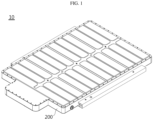
- FIG. 1 is an overall perspective view of a battery pack according to an embodiment of the present disclosure
- FIG. 2 is a perspective view showing the interior of FIG. 1
- FIG. 3 is an enlarged view of portion A in FIG. 2
- FIG. 4 is an exploded perspective view of a battery pack according to an embodiment of the present disclosure
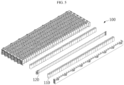
- FIG. 5 is an exploded perspective view of a battery module in a battery pack according to an embodiment of the present disclosure.
- the battery pack 10 may include a battery module 100, a pack case 200, and a cooling fluid distribution member 300.
- the battery module 100 includes a plurality of battery cells 110. And, the battery module 100 includes a plurality of cooling tubes 120. The plurality of cooling tubes 120 are disposed between the plurality of battery cells 110, and a cooling fluid for cooling the battery cells 110 flows through the cooling tubes 120. And, the battery module 100 may include a module case for accommodating the battery cells 110.
- the battery cells 110 may be provided in various types.
- the battery cells 110 may include a prismatic battery cell (not shown) or a pouch-type battery cell (not shown).
- the pouch-type battery cell may have a structure in which a unit cell arranged in the order of positive electrode plate-separator-negative electrode plate, or a bi-cell arranged in the order of positive electrode plate-separator-negative electrode plate-separator-positive electrode plate-separator-negative electrode plate are stacked in plurality according to the battery capacity.
- the pouch-type battery cell may have an electrode lead.
- the electrode lead is a type of terminal that is exposed to the outside and connected to an external device and may be made of a conductive material.
- the electrode lead may include a positive electrode lead and a negative electrode lead.
- the battery cell 110 may include a cylindrical battery cell. That is, the battery cell 110 provided in the battery pack 10 according to an embodiment of the present disclosure may vary, but the following description will focus on the case where the battery cell 110 is a cylindrical battery cell for convenience of description.
- a cylindrical battery cell may include an electrode assembly, a battery can, a positive electrode current collector plate, a cell terminal, and a negative electrode current collector plate.
- the electrode assembly includes a positive electrode plate, a negative electrode plate, and a separator, and the separator is interposed between the positive electrode plate and the negative electrode plate. And, it may be prepared as a jelly roll type in which a center hole is formed by being wound in one direction while the separator is interposed between the positive electrode plate and the negative electrode plate.
- the electrode assembly may be manufactured by winding a laminate formed by sequentially stacking a negative electrode plate, a separator, a positive electrode plate, and a separator at least once.
- the positive electrode plate and the negative electrode plate may be formed in a sheet shape. That is, the electrode assembly may be a winding type electrode assembly.
- the electrode assembly may have any winding structure well known in the related art without limitation.
- a positive electrode active material is applied on one or both sides of the positive electrode plate, and a negative electrode active material is applied on one or both sides of the negative electrode plate.
- the positive electrode active material coated on the positive electrode plate and the negative electrode active material coated on the negative electrode plate can be used without limitation as long as they are active materials known in the art.
- a porous polymer film for example, a porous polymer film made of polyolefin polymers such as ethylene homopolymer, propylene homopolymer, ethylene/butene copolymer, ethylene/hexene copolymer, ethylene/methacrylate copolymer, and the like may be used alone or by stacking them.
- the separator may be a conventional porous nonwoven fabric, for example, a nonwoven fabric made of high melting point glass fiber, polyethylene terephthalate fiber, and the like.
- At least one surface of the separator may include a coating layer of inorganic particles. It is also possible that the separator itself is made of a coating layer of inorganic particles. The particles constituting the coating layer may have a structure coupled to a binder so that an interstitial volume exists between adjacent particles.
- the battery can is formed in a cylindrical shape to accommodate an electrode assembly inside the battery can, and may be electrically connected to a negative electrode plate of the electrode assembly. Accordingly, the battery can may have the same polarity as the negative electrode plate, that is, a negative electrode, but is not limited thereto.
- a gap of a predetermined size is formed between the battery can and the electrode assembly (between the battery can and the positive electrode current collector plate when the positive electrode current collector plate is coupled to the electrode assembly), and an insulator may be interposed between the gap.
- the battery can may be made of a conductive metal, such as aluminum, steel, stainless steel, or the like, but is not limited thereto.
- the positive electrode current collector plate is electrically connected to the positive electrode plate, and for example, the positive electrode current collector plate may be connected to the positive electrode plate at the top of the electrode assembly.
- the cell terminal is made of a metal material having conductivity and is electrically connected to the positive electrode current collector plate. And, the cell terminal is electrically connected to the positive electrode plate of the electrode assembly through the positive electrode current collector plate, thereby having a positive polarity. That is, the cell terminal may function as a positive electrode terminal.
- the negative electrode current collector plate is electrically connected to the negative electrode plate.
- the negative electrode current collector plate may be made of a conductive metal material such as aluminum, steel, copper, nickel, or the like.
- the cooling tube 120 is provided in plurality.
- the cooling tube 120 may be provided in various tube shapes so that a cooling fluid for cooling the battery cell 110 flows.
- a plurality of cooling tubes 120 are disposed between the plurality of battery cells 110.
- one cooling tube 120 may cool the battery cells 110 in contact with both sides, respectively.
- the fluid flowing through the cooling tube 120 may vary, and may be, for example, water, but is not limited thereto.
- the cooling fluid may be supplied from a fluid supply member 500 (see FIG. 6 ), and the fluid supply member 500 may be connected to the cooling fluid distribution member 300.
- cooling fluid flowing through each of the plurality of cooling tubes 120 flows uniformly to improve cooling performance.
- the cooling fluid distribution member 300 is coupled to the cooling tube 120 for uniformity of cooling of the battery cells 110.
- the cooling tube 120 may be coupled to the cooling fluid distribution member 300 in various ways, and for example, the cooling tube 120 and the cooling fluid distribution member 300 may be connected in contact with each other (see FIGS. 9 and 10 ). That is, the cooling tube 120 and the coupling portion 311 of the distribution pipe 310 of the cooling fluid distribution member 300 are connected in contact with each other.
- a gasket member 400 may be provided to surround the outer side of the cooling tube 120 and the cooling fluid distribution member 300. This will be described in detail later.
- the pack case 200 accommodates the battery module 100.
- a receiving space for accommodating the battery module 100 may be provided in the pack case 200.
- various devices for controlling charge/discharge of the battery cell 110 such as a BMS, a current sensor, a fuse, and the like, may be accommodated in or coupled to the pack case 200.
- a pack lead may be coupled to the pack case 200.
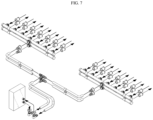
- FIG. 6 is an exploded perspective view of a cooling fluid distribution member in a battery pack according to an embodiment of the present disclosure
- FIG. 7 is a view showing the flow of a cooling fluid in FIG. 6 .
- the cooling fluid distribution member 300 distributes the cooling fluid toward the plurality of cooling tubes 120. Here, it is preferable that the cooling fluid distribution member 300 distributes the cooling fluid uniformly to each of the plurality of cooling tubes 120.
- the cooling fluid distribution member 300 may be configured to include a distribution pipe 310 and a connection pipe 320.
- the distribution pipe 310 has a plurality of coupling portions 311 each coupled to a plurality of cooling tubes 120.
- the plurality of coupling portions 311 may be formed in parallel on the distribution pipe 310.
- the coupling portion 311 may be formed in various ways, and for example, a cross-section thereof may be formed in a circular shape, but is not limited thereto. And, if necessary, the cross-section of the coupling portion 311 may be formed in more various shapes, such as a rectangle, a triangle, or other shapes. Here, the inner side of the coupling portion 311 is empty, through which the cooling fluid may move.
- the plurality of coupling portions 311 may be spaced apart from each other to have a predetermined interval, and the cooling fluid flowing through the distribution pipe 310 moves to the cooling tube 120 through the plurality of coupling portions 311.
- the coupling portion 311 is formed to protrude from the end of the distribution pipe 310, where the coupling portion 311 may be integrally formed with the distribution pipe 310, or may be manufactured separately from the distribution pipe 310 and then coupled to the distribution pipe 310.
- the distribution pipe 310 is connected to the connection pipe 320, and the cooling fluid supplied from the fluid supply member 500 moves to the distribution pipe 310 through the connection pipe 320.
- connection pipe 320 connects the distribution pipe 310 and the fluid supply member 500.
- the connection pipe 320 may be connected to the distribution pipe 310 through a pipe connection port 330. That is, the pipe connection port 330 connects the distribution pipe 310 and the connection pipe 320.
- the connection pipe 320 may be connected to the fluid supply member 500 through a connector 350. That is, the connector 350 connects the fluid supply member 500 and the connection pipe 320.
- the connection pipe 320 may include a first connection pipe 321 and a second connection pipe 322.
- the first connection pipe 321 may be coupled to the fluid supply member 500 through the connector 350.
- the second connection pipe 322 may be connected to the distribution pipe 310 through the pipe connection port 330.
- the second connection pipe 322 may be connected to the first connection pipe 321 through a multi-port 340. That is, the multi-port 340 connects the first connection pipe 321 and the second connection pipe 322.
- the multi-port 340 may vary and, for example, may be configured as a 3 way port, as shown in FIG. 6 .
- the 3 way port may be configured to connect one first connection pipe 321 and two second connection pipes 322.
- two second connection pipes 322 may be respectively coupled to the 3 way port on both sides with respect to the 3 way port, and one first connection pipe 321 disposed in a direction crossing the two second connection pipes 322 may be coupled to the 3 way port.
- FIG. 8 is a perspective view of a battery module in a battery pack according to an embodiment of the present disclosure
- FIG. 9 is a cross-sectional view of the cooling fluid distribution member and gasket member of portion B in FIG. 8
- FIG. 10 is a cross-sectional view of a partial configuration of portion B in FIG. 8
- FIG. 11 is an exploded perspective view of FIG. 10
- FIG. 12 is a partially cutaway perspective view of a gasket member in a battery pack according to an embodiment of the present disclosure.
- the gasket member 400 is provided to surround the outer side of the cooling tube 120 and the cooling fluid distribution member 300. Specifically, the gasket member 400 is provided to surround the coupling portion 311 of the distribution pipe 310 of the cooling fluid distribution member 300 and the cooling tube 120 to prevent the cooling fluid from leaking. That is, the gap between the coupling portion 311 of the distribution pipe 310 and the cooling tube 120 is sealed for sealing.
- the gasket member 400 may be formed to have different widths, thicknesses, and the like depending on the required performance.
- the gasket member 400 may be made of various materials, for example, various elastic materials. Specifically, the gasket member 400 may be made of various types of rubber, but is not limited thereto.
- the gasket member 400 may be configured to include a body portion 410 and an extension portion 420.
- a hollow 411 may be formed in the body portion 410. And, referring to FIG. 10 , the cooling tube 120 is inserted into the hollow 411 through one side of the body portion 410, the coupling portion 311 of the distribution pipe 310 is inserted through the other side of the body portion 410, and the cooling tube 120 and the coupling portion 311 come into contact with each other on the inner side the body portion 410 of the gasket member 400.
- the extension portion 420 is formed to protrude from both ends of the body portion 410.
- the extension portion 420 may be formed to spread outward from the end of the body portion 410.
- the cooling tube 120 and the coupling portion 311 may be easily inserted into the body portion 410 of the gasket member 400.
- the inner side of the body portion 410 of the gasket member 400 may have a flat shape with no protrusions or grooves formed.
- a protrusion 313 may be formed on the outer side of the coupling portion 311 of the distribution pipe 310.
- FIG. 13 is a cross-sectional view of a modified embodiment of the gasket member of FIG. 12
- FIG. 14 is a cross-sectional view of a cooling fluid distribution member having a shape corresponding to the gasket member of FIG. 13 .
- a locking protrusion 412 may be formed on the inner side of the body portion 410.
- a locking groove 312 may be formed on the outer side of the coupling portion 311 of the distribution pipe 310 of the cooling fluid distribution member 300.
- a locking groove (not shown) may also be formed on the outer side of the cooling tube 120.
- the locking protrusion 412 formed on the inner side of the body portion 410 may be coupled and fixed to the locking groove 312 on the outer side of the coupling portion 311 or the locking groove (not shown) on the outer side of the cooling tube 120.
- the locking protrusion 412 formed on the inner side of the body portion 410 may be formed to be inclined from both ends of the inner side of the body portion 410 toward the center portion, but is not limited thereto.
- a locking groove (not shown) may be formed on the inner side of the body portion 410, and a locking protrusion (not shown) may also be formed on the outer side of the coupling portion 311 of the distribution pipe 310 or the outer side of the cooling tube 120.
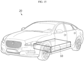
- FIG. 15 is a view for describing a vehicle including a battery pack according to an embodiment of the present disclosure.
- a vehicle 20 may include one or more battery packs 10 described above. And, the battery pack 10 according to an embodiment of the present disclosure may be applied to the vehicle 20, for example, a predetermined vehicle 20 provided to use electricity, such as an electric vehicle or a hybrid vehicle.
- the vehicle 20 according to an embodiment of the present disclosure may further include various other components included in the vehicle 20 in addition to the battery pack 10.
- the vehicle 20 according to an embodiment of the present disclosure may further include a vehicle body, a motor, or a control device such as an electronic control unit (ECU) in addition to the battery pack 10 according to an embodiment of the present disclosure.
- ECU electronice control unit
- an energy storage device includes one or more battery packs 10 according to an embodiment of the present disclosure described above.
- the energy storage device may further include general components included in energy storage devices in addition to the battery pack 10.
- the energy storage device may be a residential (building) energy storage device for home or office use, which is used to store energy in a residential home, office home, or building.
- the energy storage device may include a plurality of battery packs 10 according to an embodiment of the present disclosure electrically connected to each other.
- the energy storage device according to an embodiment of the present disclosure may further include various other components of the energy storage device known at the time of filing the present disclosure.
- this energy storage device may be used in various places or devices, such as a smart grid system or an electric charging station.
- a battery pack 10 capable of guiding uniform distribution of the cooling fluid toward the cooling tubes 120 and a vehicle 20 including the same.
- the present disclosure relates to a battery pack and a vehicle including the same, and is particularly applicable to industries related to secondary batteries.
Landscapes
- Chemical & Material Sciences (AREA)
- Chemical Kinetics & Catalysis (AREA)
- Electrochemistry (AREA)
- General Chemical & Material Sciences (AREA)
- Engineering & Computer Science (AREA)
- Manufacturing & Machinery (AREA)
- Secondary Cells (AREA)
- Battery Mounting, Suspending (AREA)
Abstract
Description
- The present application claims priority to
Korean Patent Application No. 10-2022-0186694 filed on December 28, 2022 Korean Patent Application No. 10-2023-0107852 filed on August 17, 2023 - The present disclosure relates to a battery pack and a vehicle including the same, and more specifically, to a battery pack capable of guiding uniform distribution of a cooling fluid and a vehicle including the same.
- Secondary batteries have high applicability according to product groups and electrical characteristics such as high energy density, and thus are commonly applied not only to portable devices but also to electric vehicles (EVs) or hybrid electric vehicles (HEVs) driven by electric power sources. Such secondary batteries are attracting attention as a new energy source to improve eco-friendliness and energy efficiency in that it has not only a primary advantage of dramatically reducing the use of fossil fuels, but also no by-products generated from the use of energy.
- Secondary batteries widely used at present include lithium-ion batteries, lithium polymer batteries, nickel cadmium batteries, nickel hydrogen batteries, nickel zinc batteries, and the like. An operating voltage of the unit secondary battery cell, namely a unit battery cell, is about 2.5 V to 4.5 V. Therefore, if a higher output voltage is required, a plurality of battery cells may be connected in series to configure a battery pack. In addition, depending on the charge/discharge capacity required for the battery pack, a plurality of battery cells may be connected in parallel to configure a battery pack. Thus, the number of battery cells included in the battery pack may be variously set according to the required output voltage or the demanded charge/discharge capacity.
- Meanwhile, when a plurality of battery cells are connected in series or in parallel to configure a battery pack, it is common to configure a battery module including at least one battery cell first, and then configure a battery pack or a battery rack by using such at least one battery module and adding other components.
- In the case of a conventional battery pack, it is configured to include a battery module including a plurality of battery cells and a pack case accommodating the battery module. Here, the battery module includes battery cells and may be provided with a plurality of cooling tubes through which a cooling fluid flows to cool the battery cells.
- However, in the case of a conventional battery pack, when a cooling fluid is supplied to a plurality of cooling tubes, it is difficult to distribute the cooling fluid uniformly to each cooling tube, resulting in uneven flow of the cooling fluid, whereby there is a problem of deteriorating cooling performance.
- The present disclosure is designed to solve the problems of the related art, and therefore the present disclosure is directed to providing a battery pack capable of uniformly distributing a cooling fluid to each of a plurality of cooling tubes, and a vehicle including the same.
- In addition, the present disclosure is directed to providing a battery pack that facilitates the formation of cooling channels and is more advantageous for structural design changes, and a vehicle including the same.
- However, technical problems to be solved by the present disclosure are not limited to the above-described problems, and other problems not mentioned herein may be clearly understood by those skilled in the art from the following description of the present disclosure.
- According to one aspect of the present disclosure, there may be provided a battery pack including: a battery module including a plurality of battery cells, and having a plurality of cooling tubes disposed between the plurality of battery cells and through which a cooling fluid for cooling the battery cells flows; a pack case accommodating the battery module; and a cooling fluid distribution member that distributes a cooling fluid toward the plurality of cooling tubes, wherein the cooling tube and the cooling fluid distribution member are connected in contact with each other.
- In an embodiment, the battery pack may include a gasket member surrounding the outer side of the cooling tube and the cooling fluid distribution member.
- In an embodiment, the gasket member may include a body portion in which a hollow is formed for the cooling tube and the cooling fluid distribution member to be inserted; and an extension portion protruding from both ends of the body portion.
- In an embodiment, the extension portion may be formed to spread outward from the end of the body portion.
- In an embodiment, a locking groove may be formed on the outer side of at least one of the cooling tube and the cooling fluid distribution member, and a locking protrusion may be formed on the inner side of the body portion so as to be coupled to the locking groove.
- In an embodiment, the locking protrusion may be formed to be inclined toward the center portion from both ends of the body portion.
- In an embodiment, the gasket member may be made of an elastic material.
- In an embodiment, the gasket member may be made of rubber.
- In an embodiment, the battery pack may include a fluid supply member that supplies a cooling fluid, wherein the cooling fluid distribution member may include a distribution pipe having a plurality of coupling portions respectively coupled to the plurality of cooling tubes; and a connection pipe connecting the distribution pipe and the fluid supply member.
- In an embodiment, the battery pack may include a pipe connection port connecting the distribution pipe and the connection pipe.
- In an embodiment, the connection pipe may include a first connection pipe coupled to the fluid supply member; and a second connection pipe connected to the first connection pipe and connected to the distribution pipe.
- In an embodiment, the battery pack may include a multi-port connecting the first connection pipe and the second connection pipe.
- In an embodiment, the multi-port may be configured as a 3 way port, and the 3 way port may connect one first connection pipe and two second connection pipes.
- In an embodiment, the battery pack may include a connector connecting the fluid supply member and the connection pipe.
- Meanwhile, according to another aspect of the present disclosure, there may be provided a vehicle including a battery pack described above.
- According to the various embodiments described above, there is an effect of uniformly distributing the cooling fluid to each of the plurality of cooling tubes.
- Accordingly, there is an effect of securing cooling performance through uniform flow of the cooling fluid.
- In addition, according to the various embodiments described above, there are effects of facilitating the formation of cooling channels and being more advantageous for structural design changes.
- In addition, the present disclosure may have various other effects, which will be described in each embodiment, or descriptions of effects that may be easily understood by those skilled in the art will be omitted.
- The accompanying drawings illustrate a preferred embodiment of the present disclosure and together with the foregoing disclosure, serve to provide further understanding of the technical features of the present disclosure, and thus the present disclosure is not construed as being limited to the drawing.
-
FIG. 1 is an overall perspective view of a battery pack according to an embodiment of the present disclosure. -
FIG. 2 is a perspective view showing the interior ofFIG. 1 . -
FIG. 3 is an enlarged view of portion A inFIG. 2 . -
FIG. 4 is an exploded perspective view of a battery pack according to an embodiment of the present disclosure. -
FIG. 5 is an exploded perspective view of a battery module in a battery pack according to an embodiment of the present disclosure. -
FIG. 6 is an exploded perspective view of a cooling fluid distribution member in a battery pack according to an embodiment of the present disclosure. -
FIG. 7 is a view showing the flow of a cooling fluid inFIG. 6 . -
FIG. 8 is a perspective view of a battery module in a battery pack according to an embodiment of the present disclosure. -
FIG. 9 is a cross-sectional view of the cooling fluid distribution member and gasket member of portion B inFIG. 8 . -
FIG. 10 is a cross-sectional view of a partial configuration of portion B inFIG. 8 . -
FIG. 11 is an exploded perspective view ofFIG. 10 . -
FIG. 12 is a partially cutaway perspective view of a gasket member in a battery pack according to an embodiment of the present disclosure. -
FIG. 13 is a cross-sectional view of a modified embodiment of the gasket member ofFIG. 12 . -
FIG. 14 is a cross-sectional view of a cooling fluid distribution member having a shape corresponding to the gasket member ofFIG. 13 . -
FIG. 15 is a view for describing a vehicle including a battery pack according to an embodiment of the present disclosure. - Hereinafter, preferred embodiments of the present disclosure will be described in detail with reference to the accompanying drawings. Prior to the description, it should be understood that the terms used in the specification and the appended claims should not be construed as limited to general and dictionary meanings, but interpreted based on the meanings and concepts corresponding to technical aspects of the present disclosure on the basis of the principle that the inventor is allowed to define terms appropriately for the best explanation. Therefore, the description proposed herein is just a preferable example for the purpose of illustrations only, not intended to limit the scope of the disclosure, so it should be understood that other equivalents and modifications could be made thereto without departing from the scope of the disclosure.
- In the drawings, the size of each component or a specific portion constituting the component is exaggerated, omitted, or schematically illustrated for convenience and clarity of description. Therefore, the size of each component does not fully reflect the actual size. If it is determined that a detailed description of a related known function or configuration may unnecessarily obscure the gist of the present disclosure, such a description will be omitted.
- As used herein, the term 'coupling' or 'connection' refers to not only a case where one member and another member are directly coupled or directly connected, but also a case where one member is indirectly coupled or indirectly connected to another member through a joint member.
- Throughout this specification, when a part 'includes' a component, it means that the part may further include other components rather than excluding other components unless specifically stated to the contrary.
-
FIG. 1 is an overall perspective view of a battery pack according to an embodiment of the present disclosure,FIG. 2 is a perspective view showing the interior ofFIG. 1 ,FIG. 3 is an enlarged view of portion A inFIG. 2 ,FIG. 4 is an exploded perspective view of a battery pack according to an embodiment of the present disclosure, andFIG. 5 is an exploded perspective view of a battery module in a battery pack according to an embodiment of the present disclosure. - Referring to
FIGS. 1 to 5 , thebattery pack 10 according to an embodiment of the present disclosure may include abattery module 100, apack case 200, and a coolingfluid distribution member 300. - Referring to
FIG. 5 , thebattery module 100 includes a plurality ofbattery cells 110. And, thebattery module 100 includes a plurality ofcooling tubes 120. The plurality ofcooling tubes 120 are disposed between the plurality ofbattery cells 110, and a cooling fluid for cooling thebattery cells 110 flows through the coolingtubes 120. And, thebattery module 100 may include a module case for accommodating thebattery cells 110. - The
battery cells 110 may be provided in various types. For example, thebattery cells 110 may include a prismatic battery cell (not shown) or a pouch-type battery cell (not shown). The pouch-type battery cell may have a structure in which a unit cell arranged in the order of positive electrode plate-separator-negative electrode plate, or a bi-cell arranged in the order of positive electrode plate-separator-negative electrode plate-separator-positive electrode plate-separator-negative electrode plate are stacked in plurality according to the battery capacity. And, the pouch-type battery cell may have an electrode lead. The electrode lead is a type of terminal that is exposed to the outside and connected to an external device and may be made of a conductive material. The electrode lead may include a positive electrode lead and a negative electrode lead. - Alternatively, as shown in
FIGS. 2 to 5 , thebattery cell 110 may include a cylindrical battery cell. That is, thebattery cell 110 provided in thebattery pack 10 according to an embodiment of the present disclosure may vary, but the following description will focus on the case where thebattery cell 110 is a cylindrical battery cell for convenience of description. - A cylindrical battery cell may include an electrode assembly, a battery can, a positive electrode current collector plate, a cell terminal, and a negative electrode current collector plate.
- The electrode assembly includes a positive electrode plate, a negative electrode plate, and a separator, and the separator is interposed between the positive electrode plate and the negative electrode plate. And, it may be prepared as a jelly roll type in which a center hole is formed by being wound in one direction while the separator is interposed between the positive electrode plate and the negative electrode plate.
- For example, the electrode assembly may be manufactured by winding a laminate formed by sequentially stacking a negative electrode plate, a separator, a positive electrode plate, and a separator at least once. Here, the positive electrode plate and the negative electrode plate may be formed in a sheet shape. That is, the electrode assembly may be a winding type electrode assembly. The electrode assembly may have any winding structure well known in the related art without limitation.
- A positive electrode active material is applied on one or both sides of the positive electrode plate, and a negative electrode active material is applied on one or both sides of the negative electrode plate. The positive electrode active material coated on the positive electrode plate and the negative electrode active material coated on the negative electrode plate can be used without limitation as long as they are active materials known in the art.
- And, as the separator, a porous polymer film, for example, a porous polymer film made of polyolefin polymers such as ethylene homopolymer, propylene homopolymer, ethylene/butene copolymer, ethylene/hexene copolymer, ethylene/methacrylate copolymer, and the like may be used alone or by stacking them. As another example, the separator may be a conventional porous nonwoven fabric, for example, a nonwoven fabric made of high melting point glass fiber, polyethylene terephthalate fiber, and the like.
- At least one surface of the separator may include a coating layer of inorganic particles. It is also possible that the separator itself is made of a coating layer of inorganic particles. The particles constituting the coating layer may have a structure coupled to a binder so that an interstitial volume exists between adjacent particles.
- The battery can is formed in a cylindrical shape to accommodate an electrode assembly inside the battery can, and may be electrically connected to a negative electrode plate of the electrode assembly. Accordingly, the battery can may have the same polarity as the negative electrode plate, that is, a negative electrode, but is not limited thereto.
- And, a gap of a predetermined size is formed between the battery can and the electrode assembly (between the battery can and the positive electrode current collector plate when the positive electrode current collector plate is coupled to the electrode assembly), and an insulator may be interposed between the gap. The battery can may be made of a conductive metal, such as aluminum, steel, stainless steel, or the like, but is not limited thereto.
- The positive electrode current collector plate is electrically connected to the positive electrode plate, and for example, the positive electrode current collector plate may be connected to the positive electrode plate at the top of the electrode assembly.
- The cell terminal is made of a metal material having conductivity and is electrically connected to the positive electrode current collector plate. And, the cell terminal is electrically connected to the positive electrode plate of the electrode assembly through the positive electrode current collector plate, thereby having a positive polarity. That is, the cell terminal may function as a positive electrode terminal.
- The negative electrode current collector plate is electrically connected to the negative electrode plate. The negative electrode current collector plate may be made of a conductive metal material such as aluminum, steel, copper, nickel, or the like.
- Referring to
FIG. 5 , the coolingtube 120 is provided in plurality. The coolingtube 120 may be provided in various tube shapes so that a cooling fluid for cooling thebattery cell 110 flows. And, a plurality ofcooling tubes 120 are disposed between the plurality ofbattery cells 110. In this case, onecooling tube 120 may cool thebattery cells 110 in contact with both sides, respectively. And, the fluid flowing through the coolingtube 120 may vary, and may be, for example, water, but is not limited thereto. The cooling fluid may be supplied from a fluid supply member 500 (seeFIG. 6 ), and thefluid supply member 500 may be connected to the coolingfluid distribution member 300. - It is advantageous that the cooling fluid flowing through each of the plurality of
cooling tubes 120 flows uniformly to improve cooling performance. Referring toFIGS. 2 and3 , when the coolingtube 120 is provided in plurality, the coolingfluid distribution member 300 is coupled to thecooling tube 120 for uniformity of cooling of thebattery cells 110. - The cooling
tube 120 may be coupled to the coolingfluid distribution member 300 in various ways, and for example, the coolingtube 120 and the coolingfluid distribution member 300 may be connected in contact with each other (seeFIGS. 9 and10 ). That is, the coolingtube 120 and thecoupling portion 311 of thedistribution pipe 310 of the coolingfluid distribution member 300 are connected in contact with each other. - And, a
gasket member 400 may be provided to surround the outer side of thecooling tube 120 and the coolingfluid distribution member 300. This will be described in detail later. - Referring to
FIGS. 2 and4 , thepack case 200 accommodates thebattery module 100. To this end, a receiving space for accommodating thebattery module 100 may be provided in thepack case 200. And, various devices for controlling charge/discharge of thebattery cell 110, such as a BMS, a current sensor, a fuse, and the like, may be accommodated in or coupled to thepack case 200. And, a pack lead may be coupled to thepack case 200. -
FIG. 6 is an exploded perspective view of a cooling fluid distribution member in a battery pack according to an embodiment of the present disclosure, andFIG. 7 is a view showing the flow of a cooling fluid inFIG. 6 . - The cooling
fluid distribution member 300 distributes the cooling fluid toward the plurality ofcooling tubes 120. Here, it is preferable that the coolingfluid distribution member 300 distributes the cooling fluid uniformly to each of the plurality ofcooling tubes 120. - Referring to
FIG. 6 , the coolingfluid distribution member 300 may be configured to include adistribution pipe 310 and aconnection pipe 320. Thedistribution pipe 310 has a plurality ofcoupling portions 311 each coupled to a plurality ofcooling tubes 120. The plurality ofcoupling portions 311 may be formed in parallel on thedistribution pipe 310. - The
coupling portion 311 may be formed in various ways, and for example, a cross-section thereof may be formed in a circular shape, but is not limited thereto. And, if necessary, the cross-section of thecoupling portion 311 may be formed in more various shapes, such as a rectangle, a triangle, or other shapes. Here, the inner side of thecoupling portion 311 is empty, through which the cooling fluid may move. - And, the plurality of
coupling portions 311 may be spaced apart from each other to have a predetermined interval, and the cooling fluid flowing through thedistribution pipe 310 moves to thecooling tube 120 through the plurality ofcoupling portions 311. - The
coupling portion 311 is formed to protrude from the end of thedistribution pipe 310, where thecoupling portion 311 may be integrally formed with thedistribution pipe 310, or may be manufactured separately from thedistribution pipe 310 and then coupled to thedistribution pipe 310. - Referring to
FIGS. 6 and7 , thedistribution pipe 310 is connected to theconnection pipe 320, and the cooling fluid supplied from thefluid supply member 500 moves to thedistribution pipe 310 through theconnection pipe 320. - The
connection pipe 320 connects thedistribution pipe 310 and thefluid supply member 500. Here, theconnection pipe 320 may be connected to thedistribution pipe 310 through apipe connection port 330. That is, thepipe connection port 330 connects thedistribution pipe 310 and theconnection pipe 320. And, theconnection pipe 320 may be connected to thefluid supply member 500 through aconnector 350. That is, theconnector 350 connects thefluid supply member 500 and theconnection pipe 320. - The
connection pipe 320 may include afirst connection pipe 321 and asecond connection pipe 322. Thefirst connection pipe 321 may be coupled to thefluid supply member 500 through theconnector 350. And, thesecond connection pipe 322 may be connected to thedistribution pipe 310 through thepipe connection port 330. - In addition, the
second connection pipe 322 may be connected to thefirst connection pipe 321 through a multi-port 340. That is, the multi-port 340 connects thefirst connection pipe 321 and thesecond connection pipe 322. - The multi-port 340 may vary and, for example, may be configured as a 3 way port, as shown in
FIG. 6 . Here, the 3 way port may be configured to connect onefirst connection pipe 321 and twosecond connection pipes 322. For example, twosecond connection pipes 322 may be respectively coupled to the 3 way port on both sides with respect to the 3 way port, and onefirst connection pipe 321 disposed in a direction crossing the twosecond connection pipes 322 may be coupled to the 3 way port. However, this is only one embodiment. -
FIG. 8 is a perspective view of a battery module in a battery pack according to an embodiment of the present disclosure,FIG. 9 is a cross-sectional view of the cooling fluid distribution member and gasket member of portion B inFIG. 8 ,FIG. 10 is a cross-sectional view of a partial configuration of portion B inFIG. 8 ,FIG. 11 is an exploded perspective view ofFIG. 10 , andFIG. 12 is a partially cutaway perspective view of a gasket member in a battery pack according to an embodiment of the present disclosure. - Referring to
FIGS. 8 to 12 , thegasket member 400 is provided to surround the outer side of thecooling tube 120 and the coolingfluid distribution member 300. Specifically, thegasket member 400 is provided to surround thecoupling portion 311 of thedistribution pipe 310 of the coolingfluid distribution member 300 and thecooling tube 120 to prevent the cooling fluid from leaking. That is, the gap between thecoupling portion 311 of thedistribution pipe 310 and thecooling tube 120 is sealed for sealing. Thegasket member 400 may be formed to have different widths, thicknesses, and the like depending on the required performance. - The
gasket member 400 may be made of various materials, for example, various elastic materials. Specifically, thegasket member 400 may be made of various types of rubber, but is not limited thereto. - Referring to
FIG. 12 , thegasket member 400 may be configured to include abody portion 410 and anextension portion 420. - A hollow 411 may be formed in the
body portion 410. And, referring toFIG. 10 , the coolingtube 120 is inserted into the hollow 411 through one side of thebody portion 410, thecoupling portion 311 of thedistribution pipe 310 is inserted through the other side of thebody portion 410, and thecooling tube 120 and thecoupling portion 311 come into contact with each other on the inner side thebody portion 410 of thegasket member 400. - The
extension portion 420 is formed to protrude from both ends of thebody portion 410. Theextension portion 420 may be formed to spread outward from the end of thebody portion 410. Here, when theextension portion 420 has a shape that spreads outward from thebody portion 410, the coolingtube 120 and thecoupling portion 311 may be easily inserted into thebody portion 410 of thegasket member 400. - Referring to
FIG. 12 , the inner side of thebody portion 410 of thegasket member 400 may have a flat shape with no protrusions or grooves formed. However, aprotrusion 313 may be formed on the outer side of thecoupling portion 311 of thedistribution pipe 310. -
FIG. 13 is a cross-sectional view of a modified embodiment of the gasket member ofFIG. 12 , andFIG. 14 is a cross-sectional view of a cooling fluid distribution member having a shape corresponding to the gasket member ofFIG. 13 . - Referring to
FIG. 13 , a lockingprotrusion 412 may be formed on the inner side of thebody portion 410. And, referring toFIG. 14 , a lockinggroove 312 may be formed on the outer side of thecoupling portion 311 of thedistribution pipe 310 of the coolingfluid distribution member 300. Although not shown in the drawing, a locking groove (not shown) may also be formed on the outer side of thecooling tube 120. - When the
cooling tube 120 and thecoupling portion 311 are inserted into thebody portion 410 of thegasket member 400, the lockingprotrusion 412 formed on the inner side of thebody portion 410 may be coupled and fixed to the lockinggroove 312 on the outer side of thecoupling portion 311 or the locking groove (not shown) on the outer side of thecooling tube 120. - Here, the locking
protrusion 412 formed on the inner side of thebody portion 410 may be formed to be inclined from both ends of the inner side of thebody portion 410 toward the center portion, but is not limited thereto. - Meanwhile, as a modified embodiment, a locking groove (not shown) may be formed on the inner side of the
body portion 410, and a locking protrusion (not shown) may also be formed on the outer side of thecoupling portion 311 of thedistribution pipe 310 or the outer side of thecooling tube 120. -
FIG. 15 is a view for describing a vehicle including a battery pack according to an embodiment of the present disclosure. - Referring to
FIG. 15 , avehicle 20 according to an embodiment of the present disclosure may include one or more battery packs 10 described above. And, thebattery pack 10 according to an embodiment of the present disclosure may be applied to thevehicle 20, for example, apredetermined vehicle 20 provided to use electricity, such as an electric vehicle or a hybrid vehicle. - And, the
vehicle 20 according to an embodiment of the present disclosure may further include various other components included in thevehicle 20 in addition to thebattery pack 10. For example, thevehicle 20 according to an embodiment of the present disclosure may further include a vehicle body, a motor, or a control device such as an electronic control unit (ECU) in addition to thebattery pack 10 according to an embodiment of the present disclosure. - Also, an energy storage device according to an embodiment of the present disclosure includes one or more battery packs 10 according to an embodiment of the present disclosure described above. In addition, the energy storage device according to an embodiment of the present disclosure may further include general components included in energy storage devices in addition to the
battery pack 10. In particular, the energy storage device according to an embodiment of the present disclosure may be a residential (building) energy storage device for home or office use, which is used to store energy in a residential home, office home, or building. - In addition, in order to have a large energy capacity, the energy storage device may include a plurality of battery packs 10 according to an embodiment of the present disclosure electrically connected to each other. In addition, the energy storage device according to an embodiment of the present disclosure may further include various other components of the energy storage device known at the time of filing the present disclosure. Moreover, this energy storage device may be used in various places or devices, such as a smart grid system or an electric charging station.
- According to the various embodiments described above, there may be provided a
battery pack 10 capable of guiding uniform distribution of the cooling fluid toward the coolingtubes 120 and avehicle 20 including the same. - Accordingly, it is possible to provide a
battery pack 10 capable of securing cooling performance through uniform flow of the cooling fluid and avehicle 20 including the same. - In addition, according to the various embodiments described above, it is possible to provide a
battery pack 10 that facilitates the formation of cooling channels and is more advantageous for structural design changes, and avehicle 20 including the same. - The terms indicating directions as used herein such as upper, lower, left, and right are used for convenience of description only, and it is obvious to those skilled in the art that the term may change depending on the position of the stated element or an observer.
- The present disclosure has been hereinabove described with regard to a limited number of embodiments and drawings, but the present disclosure is not limited thereto and it is obvious to those skilled in the art that a variety of modifications and changes may be made thereto within the technical aspects of the present disclosure and the equivalent scope of the appended claims. Therefore, the embodiments disclosed above should be considered from an illustrative perspective rather than a limiting perspective. That is, the scope of the true technical idea of the present disclosure is shown in the claims, and all differences within the scope of equivalents should be construed as being included in the present disclosure.
- The present disclosure relates to a battery pack and a vehicle including the same, and is particularly applicable to industries related to secondary batteries.
Claims (15)
- A battery pack, comprising:a battery module comprising a plurality of battery cells, and having a plurality of cooling tubes disposed between the plurality of battery cells and through which a cooling fluid for cooling the battery cells flows;a pack case accommodating the battery module; anda cooling fluid distribution member that distributes a cooling fluid toward the plurality of cooling tubes,wherein the cooling tube and the cooling fluid distribution member are connected in contact with each other.
- The battery pack according to claim 1, comprising
a gasket member surrounding the outer side of the cooling tube and the cooling fluid distribution member. - The battery pack according to claim 2,
wherein the gasket member comprises:a body portion in which a hollow is formed for the cooling tube and the cooling fluid distribution member to be inserted; andan extension portion protruding from both ends of the body portion. - The battery pack according to claim 3,
wherein the extension portion is formed to spread outward from the end of the body portion. - The battery pack according to claim 3,wherein a locking groove is formed on the outer side of at least one of the cooling tube and the cooling fluid distribution member, anda locking protrusion is formed on the inner side of the body portion so as to be coupled to the locking groove.
- The battery pack according to claim 5,
wherein the locking protrusion is formed to be inclined toward the center portion from both ends of the body portion. - The battery pack according to claim 2,
wherein the gasket member is made of an elastic material. - The battery pack according to claim 7,
wherein the gasket member is made of rubber. - The battery pack according to claim 1, comprisinga fluid supply member that supplies a cooling fluid,wherein the cooling fluid distribution member comprises:a distribution pipe having a plurality of coupling portions respectively coupled to the plurality of cooling tubes; anda connection pipe connecting the distribution pipe and the fluid supply member.
- The battery pack according to claim 9, comprising
a pipe connection port connecting the distribution pipe and the connection pipe. - The battery pack according to claim 9,
wherein the connection pipe comprises:a first connection pipe coupled to the fluid supply member; anda second connection pipe connected to the first connection pipe and connected to the distribution pipe. - The battery pack according to claim 11, comprising
a multi-port connecting the first connection pipe and the second connection pipe. - The battery pack according to claim 12,wherein the multi-port is configured as a 3 way port, andthe 3 way port connects one first connection pipe and two second connection pipes.
- The battery pack according to claim 9, comprising
a connector connecting the fluid supply member and the connection pipe. - A vehicle comprising a battery pack according to any one of claims 1 to 14.
Applications Claiming Priority (3)
| Application Number | Priority Date | Filing Date | Title |
|---|---|---|---|
| KR20220186694 | 2022-12-28 | ||
| KR1020230107852A KR102931724B1 (en) | 2022-12-28 | 2023-08-17 | Battery pack and vehicle comprising the same |
| PCT/KR2023/013604 WO2024143764A1 (en) | 2022-12-28 | 2023-09-11 | Battery pack and vehicle comprising same |
Publications (3)
| Publication Number | Publication Date |
|---|---|
| EP4468463A1 true EP4468463A1 (en) | 2024-11-27 |
| EP4468463A4 EP4468463A4 (en) | 2025-04-30 |
| EP4468463B1 EP4468463B1 (en) | 2025-11-05 |
Family
ID=91718041
Family Applications (1)
| Application Number | Title | Priority Date | Filing Date |
|---|---|---|---|
| EP23912448.0A Active EP4468463B1 (en) | 2022-12-28 | 2023-09-11 | Battery pack and vehicle comprising same |
Country Status (6)
| Country | Link |
|---|---|
| US (1) | US20250349934A1 (en) |
| EP (1) | EP4468463B1 (en) |
| JP (1) | JP2025515854A (en) |
| CN (1) | CN119366038A (en) |
| ES (1) | ES3053998T3 (en) |
| WO (1) | WO2024143764A1 (en) |
Families Citing this family (1)
| Publication number | Priority date | Publication date | Assignee | Title |
|---|---|---|---|---|
| CN120280660B (en) * | 2025-06-10 | 2025-09-19 | 宁德时代新能源科技股份有限公司 | Battery devices and power-consuming devices |
Family Cites Families (12)
| Publication number | Priority date | Publication date | Assignee | Title |
|---|---|---|---|---|
| GB199966A (en) * | 1922-07-20 | 1923-07-05 | Ernest Samuel Yeomans | An improved flexible connection for gas and other fittings |
| DE10034134A1 (en) * | 2000-07-13 | 2002-01-31 | Daimler Chrysler Ag | Heat exchanger structure for several electrochemical storage cells |
| DE10238235A1 (en) * | 2002-08-21 | 2004-03-04 | Daimlerchrysler Ag | Electrochemical energy store with heat exchanger structure has channel component between rows of electrochemical cells with adjacent longitudinal heat exchanger channels in adjacent cell rows |
| CN102257652B (en) * | 2008-11-12 | 2014-04-02 | 江森自控帅福得先进能源动力系统有限责任公司 | Battery system with heat exchanger |
| KR101060752B1 (en) * | 2009-09-25 | 2011-08-30 | 한국전력공사 | Helical Corrugated Joint |
| PL2610947T3 (en) * | 2010-08-23 | 2019-05-31 | Lg Chemical Ltd | Battery system including a manifold member and a connection fitting, and manifold assembly |
| KR20150035264A (en) * | 2013-09-27 | 2015-04-06 | 주식회사 엘지화학 | Manifold and secondary battery module including the same |
| JP6661476B2 (en) * | 2016-05-30 | 2020-03-11 | 昭和電工株式会社 | Liquid-cooled cooling device and method of manufacturing the same |
| EP3273500B1 (en) * | 2016-07-21 | 2018-09-12 | Samsung SDI Co., Ltd. | Battery system |
| EP3553876B1 (en) * | 2018-04-09 | 2020-07-22 | Samsung SDI Co., Ltd. | Coolant distributor |
| JP7293979B2 (en) * | 2019-08-21 | 2023-06-20 | マツダ株式会社 | vehicle battery pack |
| JP2022096755A (en) | 2020-12-18 | 2022-06-30 | ウシオ電機株式会社 | Cell system |
-
2023
- 2023-09-11 CN CN202380047217.5A patent/CN119366038A/en active Pending
- 2023-09-11 EP EP23912448.0A patent/EP4468463B1/en active Active
- 2023-09-11 WO PCT/KR2023/013604 patent/WO2024143764A1/en not_active Ceased
- 2023-09-11 ES ES23912448T patent/ES3053998T3/en active Active
- 2023-09-11 US US18/869,749 patent/US20250349934A1/en active Pending
- 2023-09-11 JP JP2024566832A patent/JP2025515854A/en active Pending
Also Published As
| Publication number | Publication date |
|---|---|
| JP2025515854A (en) | 2025-05-20 |
| WO2024143764A1 (en) | 2024-07-04 |
| EP4468463A4 (en) | 2025-04-30 |
| US20250349934A1 (en) | 2025-11-13 |
| EP4468463B1 (en) | 2025-11-05 |
| ES3053998T3 (en) | 2026-01-28 |
| CN119366038A (en) | 2025-01-24 |
Similar Documents
| Publication | Publication Date | Title |
|---|---|---|
| KR102924942B1 (en) | Battery Cell, Battery Module and Battery Pack Having the Same | |
| US20230246275A1 (en) | Battery pack and vehicle comprising same | |
| EP3676888B1 (en) | Lead tab for a battery terminal | |
| EP4468463B1 (en) | Battery pack and vehicle comprising same | |
| EP4471940B1 (en) | Battery pack and vehicle comprising same | |
| KR20140111623A (en) | Secondary battery and manufacturing method thereof | |
| EP3355380A1 (en) | Battery housing with absorbent and insulator | |
| KR102931724B1 (en) | Battery pack and vehicle comprising the same | |
| KR102954025B1 (en) | Battery pack and vehicle comprising the same | |
| US10749185B2 (en) | Secondary battery | |
| EP4258425B1 (en) | Battery module, and battery pack and vehicle comprising same | |
| KR20240101338A (en) | Battery pack and vehicle comprising the same | |
| CN118648159A (en) | Battery pack and vehicle including the battery pack | |
| EP4572078A1 (en) | Battery cell charging and discharging device and battery cell produced using same, and battery pack and vehicle comprising battery cells | |
| EP4715998A1 (en) | Secondary battery | |
| EP4576415A2 (en) | Apparatus for cleaning cylindrical battery cell and cylindrical battery cell produced using same, and battery pack and vehicle comprising cylindrical battery cell | |
| US20250253432A1 (en) | Battery Module, and Battery Pack and Vehicle Including the Same | |
| KR20250163506A (en) | Battery pack and vehicle comprising the same | |
| KR20250170474A (en) | Battery pack and vehicle comprising the same | |
| KR20260005050A (en) | Battery cell and battery pack and vehicle including the same | |
| CN120937189A (en) | Exhaust plate and secondary battery cell comprising same | |
| KR20180045926A (en) | Rechargeable battery |
Legal Events
| Date | Code | Title | Description |
|---|---|---|---|
| STAA | Information on the status of an ep patent application or granted ep patent |
Free format text: STATUS: THE INTERNATIONAL PUBLICATION HAS BEEN MADE |
|
| PUAI | Public reference made under article 153(3) epc to a published international application that has entered the european phase |
Free format text: ORIGINAL CODE: 0009012 |
|
| STAA | Information on the status of an ep patent application or granted ep patent |
Free format text: STATUS: REQUEST FOR EXAMINATION WAS MADE |
|
| 17P | Request for examination filed |
Effective date: 20240819 |
|
| AK | Designated contracting states |
Kind code of ref document: A1 Designated state(s): AL AT BE BG CH CY CZ DE DK EE ES FI FR GB GR HR HU IE IS IT LI LT LU LV MC ME MK MT NL NO PL PT RO RS SE SI SK SM TR |
|
| A4 | Supplementary search report drawn up and despatched |
Effective date: 20250402 |
|
| RIC1 | Information provided on ipc code assigned before grant |
Ipc: H01M 10/6568 20140101ALI20250327BHEP Ipc: H01M 10/625 20140101ALI20250327BHEP Ipc: H01M 10/643 20140101ALI20250327BHEP Ipc: H01M 10/613 20140101ALI20250327BHEP Ipc: H01M 10/6556 20140101AFI20250327BHEP |
|
| GRAP | Despatch of communication of intention to grant a patent |
Free format text: ORIGINAL CODE: EPIDOSNIGR1 |
|
| STAA | Information on the status of an ep patent application or granted ep patent |
Free format text: STATUS: GRANT OF PATENT IS INTENDED |
|
| INTG | Intention to grant announced |
Effective date: 20250711 |
|
| GRAS | Grant fee paid |
Free format text: ORIGINAL CODE: EPIDOSNIGR3 |
|
| P01 | Opt-out of the competence of the unified patent court (upc) registered |
Free format text: CASE NUMBER: UPC_APP_4935_4468463/2025 Effective date: 20250827 |
|
| GRAA | (expected) grant |
Free format text: ORIGINAL CODE: 0009210 |
|
| STAA | Information on the status of an ep patent application or granted ep patent |
Free format text: STATUS: THE PATENT HAS BEEN GRANTED |
|
| DAV | Request for validation of the european patent (deleted) | ||
| DAX | Request for extension of the european patent (deleted) | ||
| AK | Designated contracting states |
Kind code of ref document: B1 Designated state(s): AL AT BE BG CH CY CZ DE DK EE ES FI FR GB GR HR HU IE IS IT LI LT LU LV MC ME MK MT NL NO PL PT RO RS SE SI SK SM TR |
|
| REG | Reference to a national code |
Ref country code: CH Ref legal event code: F10 Free format text: ST27 STATUS EVENT CODE: U-0-0-F10-F00 (AS PROVIDED BY THE NATIONAL OFFICE) Effective date: 20251105 Ref country code: GB Ref legal event code: FG4D |
|
| REG | Reference to a national code |
Ref country code: DE Ref legal event code: R096 Ref document number: 602023008409 Country of ref document: DE |
|
| REG | Reference to a national code |
Ref country code: IE Ref legal event code: FG4D |
|
| REG | Reference to a national code |
Ref country code: ES Ref legal event code: FG2A Ref document number: 3053998 Country of ref document: ES Kind code of ref document: T3 Effective date: 20260128 |
|
| REG | Reference to a national code |
Ref country code: NL Ref legal event code: MP Effective date: 20251105 |
|
| REG | Reference to a national code |
Ref country code: LT Ref legal event code: MG9D |
|
| PG25 | Lapsed in a contracting state [announced via postgrant information from national office to epo] |
Ref country code: NO Free format text: LAPSE BECAUSE OF FAILURE TO SUBMIT A TRANSLATION OF THE DESCRIPTION OR TO PAY THE FEE WITHIN THE PRESCRIBED TIME-LIMIT Effective date: 20260205 |
|
| PG25 | Lapsed in a contracting state [announced via postgrant information from national office to epo] |
Ref country code: FI Free format text: LAPSE BECAUSE OF FAILURE TO SUBMIT A TRANSLATION OF THE DESCRIPTION OR TO PAY THE FEE WITHIN THE PRESCRIBED TIME-LIMIT Effective date: 20251105 Ref country code: HR Free format text: LAPSE BECAUSE OF FAILURE TO SUBMIT A TRANSLATION OF THE DESCRIPTION OR TO PAY THE FEE WITHIN THE PRESCRIBED TIME-LIMIT Effective date: 20251105 Ref country code: AT Free format text: LAPSE BECAUSE OF FAILURE TO SUBMIT A TRANSLATION OF THE DESCRIPTION OR TO PAY THE FEE WITHIN THE PRESCRIBED TIME-LIMIT Effective date: 20251105 |
|
| REG | Reference to a national code |
Ref country code: AT Ref legal event code: MK05 Ref document number: 1855402 Country of ref document: AT Kind code of ref document: T Effective date: 20251105 |
|
| PG25 | Lapsed in a contracting state [announced via postgrant information from national office to epo] |
Ref country code: NL Free format text: LAPSE BECAUSE OF FAILURE TO SUBMIT A TRANSLATION OF THE DESCRIPTION OR TO PAY THE FEE WITHIN THE PRESCRIBED TIME-LIMIT Effective date: 20251105 |
|
| PG25 | Lapsed in a contracting state [announced via postgrant information from national office to epo] |
Ref country code: RS Free format text: LAPSE BECAUSE OF FAILURE TO SUBMIT A TRANSLATION OF THE DESCRIPTION OR TO PAY THE FEE WITHIN THE PRESCRIBED TIME-LIMIT Effective date: 20260205 |
|
| PG25 | Lapsed in a contracting state [announced via postgrant information from national office to epo] |
Ref country code: IS Free format text: LAPSE BECAUSE OF FAILURE TO SUBMIT A TRANSLATION OF THE DESCRIPTION OR TO PAY THE FEE WITHIN THE PRESCRIBED TIME-LIMIT Effective date: 20260305 |
|
| PG25 | Lapsed in a contracting state [announced via postgrant information from national office to epo] |
Ref country code: PT Free format text: LAPSE BECAUSE OF FAILURE TO SUBMIT A TRANSLATION OF THE DESCRIPTION OR TO PAY THE FEE WITHIN THE PRESCRIBED TIME-LIMIT Effective date: 20260305 |
|
| PG25 | Lapsed in a contracting state [announced via postgrant information from national office to epo] |
Ref country code: PL Free format text: LAPSE BECAUSE OF FAILURE TO SUBMIT A TRANSLATION OF THE DESCRIPTION OR TO PAY THE FEE WITHIN THE PRESCRIBED TIME-LIMIT Effective date: 20251105 |
|
| PG25 | Lapsed in a contracting state [announced via postgrant information from national office to epo] |
Ref country code: LV Free format text: LAPSE BECAUSE OF FAILURE TO SUBMIT A TRANSLATION OF THE DESCRIPTION OR TO PAY THE FEE WITHIN THE PRESCRIBED TIME-LIMIT Effective date: 20251105 |