EP3676888B1 - Lead tab for a battery terminal - Google Patents
Lead tab for a battery terminal Download PDFInfo
- Publication number
- EP3676888B1 EP3676888B1 EP18759555.8A EP18759555A EP3676888B1 EP 3676888 B1 EP3676888 B1 EP 3676888B1 EP 18759555 A EP18759555 A EP 18759555A EP 3676888 B1 EP3676888 B1 EP 3676888B1
- Authority
- EP
- European Patent Office
- Prior art keywords
- lead tab
- thickness
- electrochemical cell
- concavity
- axis
- Prior art date
- Legal status (The legal status is an assumption and is not a legal conclusion. Google has not performed a legal analysis and makes no representation as to the accuracy of the status listed.)
- Active
Links
- 229920000642 polymer Polymers 0.000 claims description 17
- 229910052751 metal Inorganic materials 0.000 claims description 10
- 239000002184 metal Substances 0.000 claims description 10
- 239000011888 foil Substances 0.000 claims description 5
- 230000007704 transition Effects 0.000 claims description 4
- 238000007789 sealing Methods 0.000 description 6
- 239000000463 material Substances 0.000 description 5
- 230000002093 peripheral effect Effects 0.000 description 5
- 239000000758 substrate Substances 0.000 description 5
- 239000003792 electrolyte Substances 0.000 description 4
- HBBGRARXTFLTSG-UHFFFAOYSA-N Lithium ion Chemical compound [Li+] HBBGRARXTFLTSG-UHFFFAOYSA-N 0.000 description 3
- 239000004744 fabric Substances 0.000 description 3
- 229910001416 lithium ion Inorganic materials 0.000 description 3
- 229920006254 polymer film Polymers 0.000 description 3
- -1 polypropylene Polymers 0.000 description 3
- 239000004743 Polypropylene Substances 0.000 description 2
- 239000011149 active material Substances 0.000 description 2
- 239000011248 coating agent Substances 0.000 description 2
- 238000000576 coating method Methods 0.000 description 2
- 239000004020 conductor Substances 0.000 description 2
- 239000012528 membrane Substances 0.000 description 2
- 229920001155 polypropylene Polymers 0.000 description 2
- 238000010248 power generation Methods 0.000 description 2
- 238000012546 transfer Methods 0.000 description 2
- 238000003466 welding Methods 0.000 description 2
- OKTJSMMVPCPJKN-UHFFFAOYSA-N Carbon Chemical compound [C] OKTJSMMVPCPJKN-UHFFFAOYSA-N 0.000 description 1
- RYGMFSIKBFXOCR-UHFFFAOYSA-N Copper Chemical compound [Cu] RYGMFSIKBFXOCR-UHFFFAOYSA-N 0.000 description 1
- 239000004698 Polyethylene Substances 0.000 description 1
- 230000004075 alteration Effects 0.000 description 1
- 239000004411 aluminium Substances 0.000 description 1
- 229910052782 aluminium Inorganic materials 0.000 description 1
- XAGFODPZIPBFFR-UHFFFAOYSA-N aluminium Chemical compound [Al] XAGFODPZIPBFFR-UHFFFAOYSA-N 0.000 description 1
- 239000005030 aluminium foil Substances 0.000 description 1
- 238000003491 array Methods 0.000 description 1
- OJIJEKBXJYRIBZ-UHFFFAOYSA-N cadmium nickel Chemical compound [Ni].[Cd] OJIJEKBXJYRIBZ-UHFFFAOYSA-N 0.000 description 1
- 239000002800 charge carrier Substances 0.000 description 1
- 238000002485 combustion reaction Methods 0.000 description 1
- 238000010276 construction Methods 0.000 description 1
- 229910052802 copper Inorganic materials 0.000 description 1
- 239000010949 copper Substances 0.000 description 1
- 238000013461 design Methods 0.000 description 1
- 239000012777 electrically insulating material Substances 0.000 description 1
- 238000005516 engineering process Methods 0.000 description 1
- 239000000446 fuel Substances 0.000 description 1
- 229910002804 graphite Inorganic materials 0.000 description 1
- 239000010439 graphite Substances 0.000 description 1
- 238000003780 insertion Methods 0.000 description 1
- 230000037431 insertion Effects 0.000 description 1
- 238000009434 installation Methods 0.000 description 1
- 239000002648 laminated material Substances 0.000 description 1
- 229910052987 metal hydride Inorganic materials 0.000 description 1
- 229910044991 metal oxide Inorganic materials 0.000 description 1
- 150000004706 metal oxides Chemical class 0.000 description 1
- 238000000034 method Methods 0.000 description 1
- 229910052759 nickel Inorganic materials 0.000 description 1
- PXHVJJICTQNCMI-UHFFFAOYSA-N nickel Substances [Ni] PXHVJJICTQNCMI-UHFFFAOYSA-N 0.000 description 1
- 238000012856 packing Methods 0.000 description 1
- 229920000573 polyethylene Polymers 0.000 description 1
- 239000007787 solid Substances 0.000 description 1
Images


Classifications
-
- H—ELECTRICITY
- H01—ELECTRIC ELEMENTS
- H01M—PROCESSES OR MEANS, e.g. BATTERIES, FOR THE DIRECT CONVERSION OF CHEMICAL ENERGY INTO ELECTRICAL ENERGY
- H01M10/00—Secondary cells; Manufacture thereof
- H01M10/05—Accumulators with non-aqueous electrolyte
- H01M10/052—Li-accumulators
- H01M10/0525—Rocking-chair batteries, i.e. batteries with lithium insertion or intercalation in both electrodes; Lithium-ion batteries
-
- H—ELECTRICITY
- H01—ELECTRIC ELEMENTS
- H01M—PROCESSES OR MEANS, e.g. BATTERIES, FOR THE DIRECT CONVERSION OF CHEMICAL ENERGY INTO ELECTRICAL ENERGY
- H01M50/00—Constructional details or processes of manufacture of the non-active parts of electrochemical cells other than fuel cells, e.g. hybrid cells
- H01M50/10—Primary casings; Jackets or wrappings
- H01M50/102—Primary casings; Jackets or wrappings characterised by their shape or physical structure
- H01M50/105—Pouches or flexible bags
-
- H—ELECTRICITY
- H01—ELECTRIC ELEMENTS
- H01M—PROCESSES OR MEANS, e.g. BATTERIES, FOR THE DIRECT CONVERSION OF CHEMICAL ENERGY INTO ELECTRICAL ENERGY
- H01M50/00—Constructional details or processes of manufacture of the non-active parts of electrochemical cells other than fuel cells, e.g. hybrid cells
- H01M50/10—Primary casings; Jackets or wrappings
- H01M50/116—Primary casings; Jackets or wrappings characterised by the material
- H01M50/124—Primary casings; Jackets or wrappings characterised by the material having a layered structure
- H01M50/126—Primary casings; Jackets or wrappings characterised by the material having a layered structure comprising three or more layers
-
- H—ELECTRICITY
- H01—ELECTRIC ELEMENTS
- H01M—PROCESSES OR MEANS, e.g. BATTERIES, FOR THE DIRECT CONVERSION OF CHEMICAL ENERGY INTO ELECTRICAL ENERGY
- H01M50/00—Constructional details or processes of manufacture of the non-active parts of electrochemical cells other than fuel cells, e.g. hybrid cells
- H01M50/10—Primary casings; Jackets or wrappings
- H01M50/172—Arrangements of electric connectors penetrating the casing
- H01M50/174—Arrangements of electric connectors penetrating the casing adapted for the shape of the cells
- H01M50/178—Arrangements of electric connectors penetrating the casing adapted for the shape of the cells for pouch or flexible bag cells
-
- H—ELECTRICITY
- H01—ELECTRIC ELEMENTS
- H01M—PROCESSES OR MEANS, e.g. BATTERIES, FOR THE DIRECT CONVERSION OF CHEMICAL ENERGY INTO ELECTRICAL ENERGY
- H01M50/00—Constructional details or processes of manufacture of the non-active parts of electrochemical cells other than fuel cells, e.g. hybrid cells
- H01M50/10—Primary casings; Jackets or wrappings
- H01M50/183—Sealing members
- H01M50/19—Sealing members characterised by the material
- H01M50/193—Organic material
-
- H—ELECTRICITY
- H01—ELECTRIC ELEMENTS
- H01M—PROCESSES OR MEANS, e.g. BATTERIES, FOR THE DIRECT CONVERSION OF CHEMICAL ENERGY INTO ELECTRICAL ENERGY
- H01M50/00—Constructional details or processes of manufacture of the non-active parts of electrochemical cells other than fuel cells, e.g. hybrid cells
- H01M50/50—Current conducting connections for cells or batteries
- H01M50/543—Terminals
- H01M50/547—Terminals characterised by the disposition of the terminals on the cells
- H01M50/548—Terminals characterised by the disposition of the terminals on the cells on opposite sides of the cell
-
- H—ELECTRICITY
- H01—ELECTRIC ELEMENTS
- H01M—PROCESSES OR MEANS, e.g. BATTERIES, FOR THE DIRECT CONVERSION OF CHEMICAL ENERGY INTO ELECTRICAL ENERGY
- H01M50/00—Constructional details or processes of manufacture of the non-active parts of electrochemical cells other than fuel cells, e.g. hybrid cells
- H01M50/50—Current conducting connections for cells or batteries
- H01M50/543—Terminals
- H01M50/552—Terminals characterised by their shape
- H01M50/553—Terminals adapted for prismatic, pouch or rectangular cells
- H01M50/557—Plate-shaped terminals
-
- H—ELECTRICITY
- H01—ELECTRIC ELEMENTS
- H01M—PROCESSES OR MEANS, e.g. BATTERIES, FOR THE DIRECT CONVERSION OF CHEMICAL ENERGY INTO ELECTRICAL ENERGY
- H01M2220/00—Batteries for particular applications
- H01M2220/20—Batteries in motive systems, e.g. vehicle, ship, plane
-
- H—ELECTRICITY
- H01—ELECTRIC ELEMENTS
- H01M—PROCESSES OR MEANS, e.g. BATTERIES, FOR THE DIRECT CONVERSION OF CHEMICAL ENERGY INTO ELECTRICAL ENERGY
- H01M2220/00—Batteries for particular applications
- H01M2220/30—Batteries in portable systems, e.g. mobile phone, laptop
-
- H—ELECTRICITY
- H01—ELECTRIC ELEMENTS
- H01M—PROCESSES OR MEANS, e.g. BATTERIES, FOR THE DIRECT CONVERSION OF CHEMICAL ENERGY INTO ELECTRICAL ENERGY
- H01M50/00—Constructional details or processes of manufacture of the non-active parts of electrochemical cells other than fuel cells, e.g. hybrid cells
- H01M50/10—Primary casings; Jackets or wrappings
- H01M50/131—Primary casings; Jackets or wrappings characterised by physical properties, e.g. gas permeability, size or heat resistance
-
- Y—GENERAL TAGGING OF NEW TECHNOLOGICAL DEVELOPMENTS; GENERAL TAGGING OF CROSS-SECTIONAL TECHNOLOGIES SPANNING OVER SEVERAL SECTIONS OF THE IPC; TECHNICAL SUBJECTS COVERED BY FORMER USPC CROSS-REFERENCE ART COLLECTIONS [XRACs] AND DIGESTS
- Y02—TECHNOLOGIES OR APPLICATIONS FOR MITIGATION OR ADAPTATION AGAINST CLIMATE CHANGE
- Y02E—REDUCTION OF GREENHOUSE GAS [GHG] EMISSIONS, RELATED TO ENERGY GENERATION, TRANSMISSION OR DISTRIBUTION
- Y02E60/00—Enabling technologies; Technologies with a potential or indirect contribution to GHG emissions mitigation
- Y02E60/10—Energy storage using batteries
Definitions
- Battery packs provide power for various technologies ranging from portable electronics to renewable power systems and environmentally friendly vehicles.
- hybrid electric vehicles use a battery pack and an electric motor in conjunction with a combustion engine to increase fuel efficiency.
- Battery packs are formed of a plurality of battery modules, where each battery module includes several electrochemical cells. The cells are arranged in two or three dimensional arrays and are electrically connected in series or in parallel. Likewise, the battery modules within a battery pack are electrically connected in series or in parallel.
- each cell may include a cell housing and an electrode assembly disposed in the cell housing.
- the electrode assembly includes a series of stacked or rolled positive electrode plates that alternate with negative electrode plates and are separated by an intermediate separator plates.
- Each cell may also include a first current collector that is electrically connected to the positive electrode plates and joins the positive electrode plates to a positive cell terminal disposed outside the cell housing, and a second current collector that is electrically connected to the negative electrode plates and joins the negative electrode plates to a negative cell terminal disposed outside the cell housing.
- the first and second current collectors typically each include a lead tab that passes out of the pouch between two stacked layers of pouch fabric and along a weld line that joins the layers of pouch fabric together and forms a sealed joint.
- the lead tab is used to pass current from inside the pouch cell housing to the outside where it can be electrically connected to an external structure such as a terminal.
- a sealing tape having specialized material properties is applied to each side of the lead tab at the sealed joint where the lead tab passes between the layers and out of the pouch. The sealing tape is hot melted to the inside layer of the metal foil laminate material used to form the pouch cell housing.
- the rate of charge or discharge is due at least in part to the cross sectional area of the lead tab, where an increased lead tab thickness results in reduced electrical resistance and increased current carrying capacity.
- increased lead tab thickness sometimes results in gaps being formed between the sealing tape and the lead tab at the ends of the lead tab.
- the invention provides an electrochemical cell according to claim 1.
- the electrochemical cell includes a cell housing formed of a flexible sheet.
- the cell housing has a first housing portion, and a second housing portion that is joined to the first housing portion along a sealed joint to form a pouch.
- the electrochemical cell includes an electrode assembly disposed in the cell housing, the electrode assembly including positive electrode portions alternating with negative electrode portions. The positive electrode portions and the negative electrode portions are separated by at least one separator and stacked along a stack axis.
- the electrochemical cell also includes a lead tab that extends through the sealed joint.
- the lead tab includes a first end that is disposed inside the cell housing and is electrically connected to one of the positive electrode portions and the negative electrode portions.
- the lead tab includes a second end that is opposed to the first end and disposed outside the cell housing.
- the lead tab includes a longitudinal axis that extends between the first end and the second end, and a first cross section that is transverse to the longitudinal axis.
- the first cross section includes a width dimension that is transverse to the longitudinal axis and a thickness dimension that is transverse to both the longitudinal axis and the width dimension.
- the first cross section has a first thickness in a center of the width dimension, and a second thickness at opposed ends of the width dimension. The first thickness is larger than the second thickness, and the transition between the first thickness and the second thickness is a concavity having a first radius.
- the electrochemical cell may include one or more of the following features:
- the first cross section consists of four concavities.
- the first cross section has symmetry about a first axis and a second axis, where the first axis and the second axis are transverse to the longitudinal axis and each other.
- the first thickness has a dimension of at least 2 mm.
- the first radius is in a range of 6 mm to 9 mm.
- the thickness dimension is parallel to the stack axis.
- the flexible sheet is a laminate that includes a metal foil disposed between polymer layers.
- the cell includes a polymer tape that surrounds a circumference of the lead tab at a location corresponding to the seal joint, the polymer tape providing a seal between the lead tab and the first and second housing portions.
- the polymer tape comprises a first tape portion and a second tape portion, the first tape portion overlying a first surface of the lead tab including a first concavity, a second concavity and a first land between the first and second concavities, and the second tape portion overlying a second surface of the lead tab including a third concavity, a fourth concavity and a second land between the third and fourth concavities.
- the first cross section may be symmetric about a first transverse axis parallel to the thickness dimension and includes a concavity on each of opposed sides of the first transverse axis, the concavities on each of the opposed sides of the first transverse axis arranged such that a thickness of the first cross section is greater along the first transverse axis than at a location spaced apart from the first transverse axis.
- the electrochemical cell may include one or more of the following features:
- the first cross section is symmetric about a second transverse axis that is parallel to the width dimension and includes a concavity on each of opposed sides of the second transverse axis.
- the first cross section consists of four concavities.
- the thickness dimension is parallel to the stack axis.
- the flexible sheet is a laminate that includes a metal foil disposed between polymer layers.
- the cell includes a polymer tape that surrounds a circumference of the lead tab at a location corresponding to the seal joint, the polymer tape providing a seal between the lead tab and the first and second housing portions.
- the polymer tape comprises a first tape portion and a second tape portion, the first tape portion overlying a first surface of the lead tab including a first concavity, a second concavity and a first land between the first and second concavities, and the second tape portion overlying a second surface of the lead tab including a third concavity, a fourth concavity and a second land between the third and fourth concavities.
- the pouch cell may include an electrode assembly that is sealed within a pouch-type, metal laminated film cell housing along with an electrolyte to form a power generation and storage unit.
- the electrode assembly is a "stacked" electrode assembly that includes a series of stacked positive electrode plates alternating with negative electrode plates and separated by an intermediate separator plates.
- the pouch cell includes a lead tab.
- the lead tab forms an electrical connection with the electrode plates of a given polarity within the cell and permits transfer of current out of the cell via an opening in a seal joint of the pouch cell housing.
- the lead tab has a configuration that improves reliability of the seal between the lead tab and the opening.
- the lead tab is formed having a cross-sectional area that is sufficiently large to permit a high current capacity, which in turn allows for fast charge and discharge of the cell relative to some conventional lead tabs, as well as supporting low resistance connections (for example, less than 100 micro Ohms) to peripheral devices. Since current pouch cell geometries limit the possibilities for increasing lead tab width, an increase in cross-sectional area is achieved by providing a lead tab having an increased thickness relative to the thickness of some conventional lead tabs. For example, in some embodiments, the lead tabs may have a thickness that is greater, or much greater, than 0.2 mm. To address bonding gaps that may occur between ends of the lead tab and the sealing tape due to the increased thickness of the lead tab, the lead tab has profiled edges. The profiled edges provide the lead tab with a cross-sectional shape that allows use of conventional sealing methods including use of seal tape, and also improves reliability of the seal between the lead tab and the opening.
- the lead tab profiled edges result in a cross section that is non-uniform in thickness along width direction.
- the cross section includes concave portions that provide a transition between a maximum thickness at the center in the width direction and a minimum thickness at the tab ends in the width direction.
- a lithium-ion pouch cell 2 includes an electrode assembly 20 that is sealed within a cell housing 4 along with an electrolyte to form a power generation and storage unit.
- groups of cells 2 may be bundled together and electrically connected to form battery modules (not shown).
- battery modules may be bundled together and electrically connected to form a battery pack (not shown).
- Lead tabs 40 protrude through the cell housing 4 and form an electrical connection with the electrode plates within the cell 2 and permit transfer of current out of the cell 2. To that end, each lead tab 40 exits the cell housing 4 via an opening 16 in a sealed joint 12 of the pouch cell housing 4.
- the lead tabs 40 have a configuration that improves the effectiveness and reliability of the seal between the lead tab 40 and the cell housing 4, as discussed in detail below.
- the pouch-type cell housing 4 is an assembly of two blanks of a metal laminated polymer film sheet.
- the material used to form the housing 4 is a flexible, three-layer, metal laminated film having a polypropylene layer, an aluminium foil layer, and a polyethylene layer.
- Each blank is drawn to form the shape of an open-ended box in which the open end is surrounded by a flange.
- the first blank corresponds to a first housing portion 6 that includes a central first recess 7 surrounded by a first flange 8.
- the second blank corresponds to a second housing portion 9 including a central second recess 10 surrounded by a second flange 11.
- the first and second housing portions 6, 9 are assembled together such that the first flange 8 abuts the second flange 11, and such that the first recess 7 and the second recess 10 cooperate to form a rectangular enclosure 14 that defines an interior space that is dimensioned to receive the electrode assembly 20.
- the first and second flanges 8, 11 are joined, for example via welding.
- a continuous sealed joint 12 is formed along the flanges 8, 11.
- the sealed joint 12 surrounds the enclosure 14.
- the electrode assembly 20 is disposed in the enclosure 14 and includes at least one positive electrode 22, at least one negative electrode 24 and a separator 26 that is disposed between each pair of the positive electrode 22 and the negative electrode 24.
- Each of the positive electrodes 22, the negative electrodes 24 and the separators 26 are thin plates, and each of the positive and negative electrodes 22, 24 have a layered structure to facilitate insertion and/or movement of lithium-ions.
- the positive electrodes 22 may include a first substrate formed of a first electrically-conductive material such as copper, and a first active material such as a graphite coating that is disposed on one or both sides of the first substrate.
- negative electrodes 24 may include a second substrate formed of a second electrically-conductive material such as aluminium, and a second active material such as a lithiated metal oxide coating that is disposed on one or both sides of the second substrate.
- the substrates used to form the positive and negative electrodes 22, 24 are very thin (e.g., having a thickness on the order of about 0.04 to 0.15 mm) compared to the overall cell height (e.g. having a height in a range of 10 to 40 mm) and thus are illustrated schematically and not to scale in the figures.
- the separator 26 is a permeable membrane that functions to keep the positive and negative electrodes 22, 24 apart to prevent electrical short circuits while also allowing passage of ionic charge carriers provided in the electrolyte and that are needed to close the circuit during the passage of current within the cell 2.
- the separator 26 is formed of an electrically insulating material such as a tri-layer polypropylene-polyethylene-polypropylene membrane.
- the positive electrodes 22 and negative electrodes 24 are arranged in a stacked or layered configuration in which a separator 26 is disposed (e.g., sandwiched) between each pair of the positive and negative electrodes 22, 24.
- a stack axis 28 of the electrode assembly 20 extends through a center of the electrode assembly 20 in a direction parallel to the stacking direction.
- the positive electrodes 22, the negative electrodes 24 and the separators 26 are stacked along the stack axis 28.
- the peripheral edges of each of the plates 22, 24, 26 are aligned in a direction parallel to the direction of the stack axis 28 (shown), while in other embodiments, the peripheral edges of the positive electrodes 22 are offset to one side of the stack axis 28, while the peripheral edges of the negative electrodes 24 are offset to an opposed side of the stack axis 28 (not shown).
- the particular alignment of the peripheral edges facilitates connection of the electrodes 22, 24 to corresponding lead tabs 40, 80 which in turn provide an electrical connection with the respective terminals (not shown) of the cell 2.
- the edge alignment is determined based on requirements of the specific application.
- a first lead tab 40 is used to provide an electrical connection with the positive electrodes 22, and a second lead tab 80 is used to provide an electrical connection with the negative electrodes 24.
- the first lead tab 40 protrudes from one side of the enclosure 14, and the second lead tab 80 protrudes from an opposed side of the enclosure 14.
- the first and second lead tabs 40, 80 protrude from the same side of the enclosure 14.
- the first and second lead tabs 40, 80 are identical, and so only the first lead tab 40 will be described in detail.
- the first lead tab 40 is an electrically conductive, elongate, thin plate that includes a first end 41 that is disposed inside the housing 4 and is electrically connected to the positive electrodes 22, a second end 42 that is opposed to the first end 41 and is disposed outside the housing 4, and a longitudinal axis 43 that extends between the first end 41 and the second end 42.
- the first lead tab 40 includes a first surface 44 that faces the first flange 8, and a second surface 45 that faces the second flange 11. The spacing between the first and second surfaces 44, 45 corresponds to a thickness t of the first lead tab 40.
- the first and second surfaces 44, 45 are joined at one side by a first edge 46 that extends between the first and second ends 41, 42, and are joined at the opposed side by a second edge 47 that extends between the first and second ends 41, 42.
- the first and second edges 46, 47 extend along a length of the first lead tab 40 in parallel with the lead tab longitudinal axis 43.
- the spacing between the first and second edges 46, 47 corresponds to a width w of the first lead tab 40.
- the width direction is illustrated using a double headed arrow having a reference number 54
- the thickness direction is illustrated using a double headed arrow having a reference number 56.
- the thickness of the first lead tab 40 is non-uniform along the width direction 54.
- a cross section of the lead tab 40 that is transverse to the longitudinal axis 43 has a first thickness t1 in a center portion of the width dimension, and a second thickness t2 at opposed ends of the width dimension (e.g., at the first and second edges 46, 47), where the first thickness t1 is larger than the second thickness t2.
- the transition between the first thickness t1 and the second thickness t2 has a concave profile, and the concave profile has a first radius R1.
- the lead tab cross section consists of the four concavities 58, 60, 62, 64.
- the first concavity 58 is formed in the first surface 44 at a location between the center 50 of the cross section and the first edge 46, and the first concavity 58 extends to the first edge 46.
- the second concavity 60 is formed in the first surface 44 at a location between the center 50 of the cross section and the second edge 47, and the second concavity 60 extends to the second edge 47.
- the third concavity 62 is formed in the second surface 45 at a location between the center 50 of the cross section and the second edge 47, and the third concavity extends to the second edge 47.
- the fourth concavity 64 is formed in the second surface 45 at a location between the center 50 of the cross section and the first edge 46, and the fourth concavity 64 extends to the first edge 46.
- the lead tab cross section has symmetry about a first axis 49 parallel to the thickness direction 56 and a second axis 48 parallel to the width direction 54, where the first axis 49 and the second axis 48 pass through the center 50 of the cross section, and are transverse to the longitudinal axis 43 and to each other.
- the concavities 58, 60, 62, 64 are formed at a location that is closer to the center 50 of the cross section than the corresponding first or second edge 46, 47.
- the portion of the cross section that has the first thickness t1 has a smaller width dimension than does the portion of the cross section that has the second thickness t2.
- the first thickness t1, the second thickness t2, and the first radius R1 are determined based on the requirements of the application.
- the first thickness t1 has a dimension of at least 1 mm, 2 mm, or 3 mm
- the second thickness has a dimension of 0.2 mm
- the first radius R1 has a dimension in a range of 6 to 9 mm.
- the lead tab 40 extends through an opening 16 in the sealed joint 12.
- the opening 16 is provided between a portion of the flange 8 of the first housing portion 6 and a facing portion of the flange 11 of the second housing portion 9.
- a polymer seal tape 90 surrounds a circumference of each lead tab 40, 80 at a location corresponding to the opening 16.
- the seal tape 90 provides a seal between the lead tab 40 and the facing flange 8, 11.
- the seal tape 90 is required to have very specific material properties. For example, the seal tape 90 is required to remain solid, tacky and pliable in all conditions except when localized heat is applied as occurs during the pouch fabric welding operation. When localized heat is applied, the seal tape 90 is required to melt, flow into open gaps between materials, and bond to both the pouch material and the respective lead tabs 40.
- the seal tape 90 includes a first tape portion 92 and a second tape portion 94.
- the first tape portion 92 overlies the first surface 44 of the lead tab 40 including the first concavity 58, the second concavity 60 and the first land 59 between the first and second concavities 58, 60.
- the first tape portion 92 is disposed between the lead tab first surface 44 and the first housing portion flange 8, and has sufficient length to extend outward beyond the respective first and second edges 46, 47 of the lead tab 40.
- the second tape portion 94 overlies the second surface 45 of the lead tab 40 including the third concavity 62, the fourth concavity 64 and the second land 63 between the third and fourth concavities 62, 64.
- the second tape portion 94 is disposed between the lead tab second surface 45 and the second housing portion flange 11, and has sufficient length to extend outward beyond the respective first and second edges 46, 47 of the lead tab and contact the first tape portion 92.
- the seal tape 90 including the first and second tape portions 92, 94, surrounds a circumference of the lead tab 40 at a location corresponding to the seal joint 12.
- the lead tab 40 has the thickness t2 at the first and second edges 46, 47, and the thickness 52 is relatively small for example 0.2 mm or less, the first and second tape portions 92, 94 join to each other and the lead tab first and second edges 46, 47 in such a way that a hermetic seal is formed between the lead tab 40, 80 and the opening 16 in the cell housing 4.
- the pouch-type cell housing 4 is an assembly of two blanks of a metal laminated polymer film sheet, where each blank is drawn to form the shape of an open-ended box.
- the pouch-type cell housing is not limited to this construction.
- the pouch-type cell housing may be formed of a sheet of a metal laminated polymer film that is folded to form a recess that receives the electrode assembly, and folded and sealed to form a closed pouch.
- the cell housing 4 is not limited to this shape.
- the cell housing 4 may be cube shaped, or may have other polygonal shapes that permit close packing such as an eight surface structure having hexagonally arranged sides (not shown).
- the cell 2 is not limited to being a lithium-ion battery.
- the cell 2 may be an aluminum-ion, alkaline, nickel-cadmium, nickel metal hydride, or other type of cell.
Landscapes
- Chemical & Material Sciences (AREA)
- Chemical Kinetics & Catalysis (AREA)
- Electrochemistry (AREA)
- General Chemical & Material Sciences (AREA)
- Engineering & Computer Science (AREA)
- Materials Engineering (AREA)
- Manufacturing & Machinery (AREA)
- Connection Of Batteries Or Terminals (AREA)
- Sealing Battery Cases Or Jackets (AREA)
- Secondary Cells (AREA)
Description
- Battery packs provide power for various technologies ranging from portable electronics to renewable power systems and environmentally friendly vehicles. For example, hybrid electric vehicles (HEV) use a battery pack and an electric motor in conjunction with a combustion engine to increase fuel efficiency. Battery packs are formed of a plurality of battery modules, where each battery module includes several electrochemical cells. The cells are arranged in two or three dimensional arrays and are electrically connected in series or in parallel. Likewise, the battery modules within a battery pack are electrically connected in series or in parallel.
- Different cell types have emerged in order to deal with the space requirements of a very wide variety of installation situations, and the most common types used in automobiles are cylindrical cells, prismatic cells, and pouch cells. Regardless of cell type, each cell may include a cell housing and an electrode assembly disposed in the cell housing. The electrode assembly includes a series of stacked or rolled positive electrode plates that alternate with negative electrode plates and are separated by an intermediate separator plates. Each cell may also include a first current collector that is electrically connected to the positive electrode plates and joins the positive electrode plates to a positive cell terminal disposed outside the cell housing, and a second current collector that is electrically connected to the negative electrode plates and joins the negative electrode plates to a negative cell terminal disposed outside the cell housing.
- In a pouch cell, the first and second current collectors typically each include a lead tab that passes out of the pouch between two stacked layers of pouch fabric and along a weld line that joins the layers of pouch fabric together and forms a sealed joint. The lead tab is used to pass current from inside the pouch cell housing to the outside where it can be electrically connected to an external structure such as a terminal. A sealing tape having specialized material properties is applied to each side of the lead tab at the sealed joint where the lead tab passes between the layers and out of the pouch. The sealing tape is hot melted to the inside layer of the metal foil laminate material used to form the pouch cell housing.
- It is advantageous to be able to quickly charge and discharge the electrochemical cell. The rate of charge or discharge is due at least in part to the cross sectional area of the lead tab, where an increased lead tab thickness results in reduced electrical resistance and increased current carrying capacity. However, increased lead tab thickness sometimes results in gaps being formed between the sealing tape and the lead tab at the ends of the lead tab. Thus, it is desirable to provide a lead tab that has sufficient thickness to meet current carrying capacity requirements while forming a reliable seal with the pouch cell opening via the sealing tape.
-
US 2011/0129726 A1 describes an electrochemical device. - The invention provides an electrochemical cell according to claim 1.
- The electrochemical cell includes a cell housing formed of a flexible sheet. The cell housing has a first housing portion, and a second housing portion that is joined to the first housing portion along a sealed joint to form a pouch. The electrochemical cell includes an electrode assembly disposed in the cell housing, the electrode assembly including positive electrode portions alternating with negative electrode portions. The positive electrode portions and the negative electrode portions are separated by at least one separator and stacked along a stack axis. The electrochemical cell also includes a lead tab that extends through the sealed joint. The lead tab includes a first end that is disposed inside the cell housing and is electrically connected to one of the positive electrode portions and the negative electrode portions. The lead tab includes a second end that is opposed to the first end and disposed outside the cell housing. The lead tab includes a longitudinal axis that extends between the first end and the second end, and a first cross section that is transverse to the longitudinal axis. The first cross section includes a width dimension that is transverse to the longitudinal axis and a thickness dimension that is transverse to both the longitudinal axis and the width dimension. The first cross section has a first thickness in a center of the width dimension, and a second thickness at opposed ends of the width dimension. The first thickness is larger than the second thickness, and the transition between the first thickness and the second thickness is a concavity having a first radius.
- The electrochemical cell may include one or more of the following features: The first cross section consists of four concavities. The first cross section has symmetry about a first axis and a second axis, where the first axis and the second axis are transverse to the longitudinal axis and each other. The first thickness has a dimension of at least 2 mm. The first radius is in a range of 6 mm to 9 mm. The thickness dimension is parallel to the stack axis. The flexible sheet is a laminate that includes a metal foil disposed between polymer layers. The cell includes a polymer tape that surrounds a circumference of the lead tab at a location corresponding to the seal joint, the polymer tape providing a seal between the lead tab and the first and second housing portions. The polymer tape comprises a first tape portion and a second tape portion, the first tape portion overlying a first surface of the lead tab including a first concavity, a second concavity and a first land between the first and second concavities, and the second tape portion overlying a second surface of the lead tab including a third concavity, a fourth concavity and a second land between the third and fourth concavities.
- The first cross section may be symmetric about a first transverse axis parallel to the thickness dimension and includes a concavity on each of opposed sides of the first transverse axis, the concavities on each of the opposed sides of the first transverse axis arranged such that a thickness of the first cross section is greater along the first transverse axis than at a location spaced apart from the first transverse axis.
- The electrochemical cell may include one or more of the following features: The first cross section is symmetric about a second transverse axis that is parallel to the width dimension and includes a concavity on each of opposed sides of the second transverse axis. The first cross section consists of four concavities. The thickness dimension is parallel to the stack axis. The flexible sheet is a laminate that includes a metal foil disposed between polymer layers. The cell includes a polymer tape that surrounds a circumference of the lead tab at a location corresponding to the seal joint, the polymer tape providing a seal between the lead tab and the first and second housing portions. The polymer tape comprises a first tape portion and a second tape portion, the first tape portion overlying a first surface of the lead tab including a first concavity, a second concavity and a first land between the first and second concavities, and the second tape portion overlying a second surface of the lead tab including a third concavity, a fourth concavity and a second land between the third and fourth concavities.
- The pouch cell may include an electrode assembly that is sealed within a pouch-type, metal laminated film cell housing along with an electrolyte to form a power generation and storage unit. The electrode assembly is a "stacked" electrode assembly that includes a series of stacked positive electrode plates alternating with negative electrode plates and separated by an intermediate separator plates. In addition, the pouch cell includes a lead tab. The lead tab forms an electrical connection with the electrode plates of a given polarity within the cell and permits transfer of current out of the cell via an opening in a seal joint of the pouch cell housing. The lead tab has a configuration that improves reliability of the seal between the lead tab and the opening.
- In particular, the lead tab is formed having a cross-sectional area that is sufficiently large to permit a high current capacity, which in turn allows for fast charge and discharge of the cell relative to some conventional lead tabs, as well as supporting low resistance connections (for example, less than 100 micro Ohms) to peripheral devices. Since current pouch cell geometries limit the possibilities for increasing lead tab width, an increase in cross-sectional area is achieved by providing a lead tab having an increased thickness relative to the thickness of some conventional lead tabs. For example, in some embodiments, the lead tabs may have a thickness that is greater, or much greater, than 0.2 mm. To address bonding gaps that may occur between ends of the lead tab and the sealing tape due to the increased thickness of the lead tab, the lead tab has profiled edges. The profiled edges provide the lead tab with a cross-sectional shape that allows use of conventional sealing methods including use of seal tape, and also improves reliability of the seal between the lead tab and the opening.
- The lead tab profiled edges result in a cross section that is non-uniform in thickness along width direction. The cross section includes concave portions that provide a transition between a maximum thickness at the center in the width direction and a minimum thickness at the tab ends in the width direction.
-
-
Fig. 1 is a perspective view of a portion of a pouch cell including a lead tab protruding through a seal joint and sealed therein using a seal tape. -
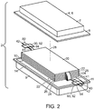
Fig. 2 is an exploded perspective view of the pouch cell ofFig. 1 . -
Fig. 3 is a perspective view of a portion of a lead tab isolated from the pouch cell ofFig. 1 . -
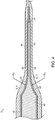
Fig. 4 is a cross sectional view of the pouch cell ofFig. 1 as seen across line 3-3 ofFig. 1 . - Referring to
Figs. 1-4 , a lithium-ion pouch cell 2 includes anelectrode assembly 20 that is sealed within a cell housing 4 along with an electrolyte to form a power generation and storage unit. In some embodiments, groups ofcells 2 may be bundled together and electrically connected to form battery modules (not shown). Likewise, battery modules may be bundled together and electrically connected to form a battery pack (not shown). Leadtabs 40 protrude through the cell housing 4 and form an electrical connection with the electrode plates within thecell 2 and permit transfer of current out of thecell 2. To that end, eachlead tab 40 exits the cell housing 4 via anopening 16 in a sealed joint 12 of the pouch cell housing 4. Thelead tabs 40 have a configuration that improves the effectiveness and reliability of the seal between thelead tab 40 and the cell housing 4, as discussed in detail below. - The pouch-type cell housing 4 is an assembly of two blanks of a metal laminated polymer film sheet. For example, in the illustrated embodiment, the material used to form the housing 4 is a flexible, three-layer, metal laminated film having a polypropylene layer, an aluminium foil layer, and a polyethylene layer. Each blank is drawn to form the shape of an open-ended box in which the open end is surrounded by a flange. The first blank corresponds to a first housing portion 6 that includes a central
first recess 7 surrounded by afirst flange 8. The second blank corresponds to a second housing portion 9 including a centralsecond recess 10 surrounded by asecond flange 11. The first and second housing portions 6, 9 are assembled together such that thefirst flange 8 abuts thesecond flange 11, and such that thefirst recess 7 and thesecond recess 10 cooperate to form arectangular enclosure 14 that defines an interior space that is dimensioned to receive theelectrode assembly 20. With theelectrode assembly 20 and the electrolyte disposed within theenclosure 14, the first andsecond flanges flanges enclosure 14. - The
electrode assembly 20 is disposed in theenclosure 14 and includes at least onepositive electrode 22, at least onenegative electrode 24 and aseparator 26 that is disposed between each pair of thepositive electrode 22 and thenegative electrode 24. Each of thepositive electrodes 22, thenegative electrodes 24 and theseparators 26 are thin plates, and each of the positive andnegative electrodes positive electrodes 22 may include a first substrate formed of a first electrically-conductive material such as copper, and a first active material such as a graphite coating that is disposed on one or both sides of the first substrate. In addition,negative electrodes 24 may include a second substrate formed of a second electrically-conductive material such as aluminium, and a second active material such as a lithiated metal oxide coating that is disposed on one or both sides of the second substrate. The substrates used to form the positive andnegative electrodes - The
separator 26 is a permeable membrane that functions to keep the positive andnegative electrodes cell 2. Theseparator 26 is formed of an electrically insulating material such as a tri-layer polypropylene-polyethylene-polypropylene membrane. - The
positive electrodes 22 andnegative electrodes 24 are arranged in a stacked or layered configuration in which aseparator 26 is disposed (e.g., sandwiched) between each pair of the positive andnegative electrodes stack axis 28 of theelectrode assembly 20 extends through a center of theelectrode assembly 20 in a direction parallel to the stacking direction. In the stacked configuration, thepositive electrodes 22, thenegative electrodes 24 and theseparators 26 are stacked along thestack axis 28. In some embodiments, the peripheral edges of each of theplates positive electrodes 22 are offset to one side of thestack axis 28, while the peripheral edges of thenegative electrodes 24 are offset to an opposed side of the stack axis 28 (not shown). The particular alignment of the peripheral edges facilitates connection of theelectrodes lead tabs cell 2. Thus, the edge alignment is determined based on requirements of the specific application. - A
first lead tab 40 is used to provide an electrical connection with thepositive electrodes 22, and asecond lead tab 80 is used to provide an electrical connection with thenegative electrodes 24. In the illustrated embodiment, thefirst lead tab 40 protrudes from one side of theenclosure 14, and thesecond lead tab 80 protrudes from an opposed side of theenclosure 14. However, in other embodiments, the first and secondlead tabs enclosure 14. The first and secondlead tabs first lead tab 40 will be described in detail. - The
first lead tab 40 is an electrically conductive, elongate, thin plate that includes afirst end 41 that is disposed inside the housing 4 and is electrically connected to thepositive electrodes 22, asecond end 42 that is opposed to thefirst end 41 and is disposed outside the housing 4, and alongitudinal axis 43 that extends between thefirst end 41 and thesecond end 42. Thefirst lead tab 40 includes afirst surface 44 that faces thefirst flange 8, and asecond surface 45 that faces thesecond flange 11. The spacing between the first andsecond surfaces first lead tab 40. The first andsecond surfaces first edge 46 that extends between the first and second ends 41, 42, and are joined at the opposed side by asecond edge 47 that extends between the first and second ends 41, 42. The first andsecond edges first lead tab 40 in parallel with the lead tablongitudinal axis 43. In addition, the spacing between the first andsecond edges first lead tab 40. InFig. 3 , the width direction is illustrated using a double headed arrow having areference number 54, and the thickness direction is illustrated using a double headed arrow having areference number 56. - The thickness of the
first lead tab 40 is non-uniform along thewidth direction 54. In particular, a cross section of thelead tab 40 that is transverse to thelongitudinal axis 43 has a first thickness t1 in a center portion of the width dimension, and a second thickness t2 at opposed ends of the width dimension (e.g., at the first andsecond edges 46, 47), where the first thickness t1 is larger than the second thickness t2. The transition between the first thickness t1 and the second thickness t2 has a concave profile, and the concave profile has a first radius R1. The lead tab cross section consists of the fourconcavities first concavity 58 is formed in thefirst surface 44 at a location between thecenter 50 of the cross section and thefirst edge 46, and thefirst concavity 58 extends to thefirst edge 46. Thesecond concavity 60 is formed in thefirst surface 44 at a location between thecenter 50 of the cross section and thesecond edge 47, and thesecond concavity 60 extends to thesecond edge 47. Thethird concavity 62 is formed in thesecond surface 45 at a location between thecenter 50 of the cross section and thesecond edge 47, and the third concavity extends to thesecond edge 47. Thefourth concavity 64 is formed in thesecond surface 45 at a location between thecenter 50 of the cross section and thefirst edge 46, and thefourth concavity 64 extends to thefirst edge 46. As a result, the lead tab cross section has symmetry about afirst axis 49 parallel to thethickness direction 56 and asecond axis 48 parallel to thewidth direction 54, where thefirst axis 49 and thesecond axis 48 pass through thecenter 50 of the cross section, and are transverse to thelongitudinal axis 43 and to each other. - In the illustrated embodiment, the
concavities center 50 of the cross section than the corresponding first orsecond edge - The first thickness t1, the second thickness t2, and the first radius R1 are determined based on the requirements of the application. For example, in some embodiments, the first thickness t1 has a dimension of at least 1 mm, 2 mm, or 3 mm, the second thickness has a dimension of 0.2 mm, and the first radius R1 has a dimension in a range of 6 to 9 mm.
- In use, the
lead tab 40 extends through anopening 16 in the sealed joint 12. Theopening 16 is provided between a portion of theflange 8 of the first housing portion 6 and a facing portion of theflange 11 of the second housing portion 9. A polymer seal tape 90 surrounds a circumference of eachlead tab opening 16. The seal tape 90 provides a seal between thelead tab 40 and the facingflange respective lead tabs 40. - The seal tape 90 includes a
first tape portion 92 and asecond tape portion 94. Thefirst tape portion 92 overlies thefirst surface 44 of thelead tab 40 including thefirst concavity 58, thesecond concavity 60 and thefirst land 59 between the first andsecond concavities first tape portion 92 is disposed between the lead tabfirst surface 44 and the firsthousing portion flange 8, and has sufficient length to extend outward beyond the respective first andsecond edges lead tab 40. In addition, thesecond tape portion 94 overlies thesecond surface 45 of thelead tab 40 including thethird concavity 62, thefourth concavity 64 and thesecond land 63 between the third andfourth concavities second tape portion 94 is disposed between the lead tabsecond surface 45 and the secondhousing portion flange 11, and has sufficient length to extend outward beyond the respective first andsecond edges first tape portion 92. As a result, the seal tape 90, including the first andsecond tape portions lead tab 40 at a location corresponding to the seal joint 12. Since thelead tab 40 has the thickness t2 at the first andsecond edges second tape portions second edges lead tab opening 16 in the cell housing 4. - In the illustrated embodiment, the pouch-type cell housing 4 is an assembly of two blanks of a metal laminated polymer film sheet, where each blank is drawn to form the shape of an open-ended box. However, the pouch-type cell housing is not limited to this construction. For example, in some embodiments, the pouch-type cell housing may be formed of a sheet of a metal laminated polymer film that is folded to form a recess that receives the electrode assembly, and folded and sealed to form a closed pouch.
- Although the
cell 2 has a low profile, rectangular-shaped cell housing 4, the cell housing 4 is not limited to this shape. For example, the cell housing 4 may be cube shaped, or may have other polygonal shapes that permit close packing such as an eight surface structure having hexagonally arranged sides (not shown). - Moreover, the
cell 2 is not limited to being a lithium-ion battery. For example, thecell 2 may be an aluminum-ion, alkaline, nickel-cadmium, nickel metal hydride, or other type of cell. - Selective illustrative embodiments of the battery system including the cell are described above in some detail. It should be understood that only structures considered necessary for clarifying these devices have been described herein. Other conventional structures, and those of ancillary and auxiliary components of the battery system, are assumed to be known and understood by those skilled in the art. Moreover, while working examples of the battery system and battery cell have been described above, the battery system and/or battery cell are not limited to the working examples described above, but various design alterations may be carried out without departing from the devices as set forth in the claims.
Claims (16)
- An electrochemical cell (2) comprising,a cell housing (4) formed of a flexible sheet, the cell housing (4) having a first housing portion (6), and a second housing portion (9) that is joined to the first housing portion (6) along a sealed joint (12) to form a pouch,an electrode assembly (20) disposed in the cell housing (4), the electrode assembly (20) including positive electrode portions alternating with negative electrode portions, the positive electrode portions and the negative electrode portions being separated by at least one separator (26) and stacked along a stack axis (28), anda lead tab (40) that extends through the sealed joint (12), the lead tab (40) includinga first end (41) that is disposed inside the cell housing (4) and is electrically connected to one of the positive electrode portions and the negative electrode portions,a second end (42) that is opposed to the first end (41) and disposed outside the cell housing (4),a longitudinal axis (43) that extends between the first end (41) and the second end (42), anda first cross section that is transverse to the longitudinal axis (43), the first cross section including a width dimension that is transverse to the longitudinal axis (43) and a thickness dimension that is transverse to both the longitudinal axis (43) and the width dimension, whereinthe first cross section has a first thickness (t1) in a center of the width dimension, and a second thickness (t2) at opposed ends of the width dimension, where the first thickness (t1) is larger than the second thickness (t2), and the transition between the first thickness (t1) and the second thickness (t2) is a concavity having a first radius (R1).
- The electrochemical cell (2) of claim 1, wherein the first cross section consists of four concavities (58, 60, 62, 64).
- The electrochemical cell (2) of claim 1, wherein the first cross section has symmetry about a first axis (49) and a second axis (48), where the first axis (49) and the second axis (48) are transverse to the longitudinal axis (43) and each other.
- The electrochemical cell (2) of claim 1, wherein the first thickness (t1) has a dimension of at least 2 mm.
- The electrochemical cell (2) of claim 1, wherein the first radius (R1) is in a range of 6 mm to 9 mm.
- The electrochemical cell (2) of claim 1, wherein the thickness dimension is parallel to the stack axis (28).
- The electrochemical cell (2) of claim 1, wherein the flexible sheet is a laminate that includes a metal foil disposed between polymer layers.
- The electrochemical cell (2) of claim 1, comprising a polymer tape that surrounds a circumference of the lead tab (40) at a location corresponding to the seal joint (12), the polymer tape providing a seal between the lead tab (40) and the first and second housing portions (6, 9).
- The electrochemical cell (2) of claim 8, wherein the polymer tape comprises a first tape portion (92) and a second tape portion (94), the first tape portion (92) overlying a first surface (44) of the lead tab (40) including a first concavity (58), a second concavity (60) and a first land (59) between the first and second concavities (58, 60), and the second tape portion (94) overlying a second surface (45) of the lead tab (40) including a third concavity (62) , a fourth concavity (64) and a second land (63) between the third and fourth concavities (62, 64).
- The electrochemical cell (2) of claim 1, wherein
the first cross section is symmetric about a first transverse axis parallel to the thickness dimension and includes the concavity on each of opposed sides of the first transverse axis, the concavities on each of the opposed sides of the first transverse axis arranged such that a thickness of the first cross section is greater along the first transverse axis than at a location spaced apart from the first transverse axis. - The electrochemical cell (2) of claim 10, wherein the first cross section is symmetric about a second transverse axis that is parallel to the width dimension and includes the concavity on each of opposed sides of the second transverse axis.
- The electrochemical cell (2) of claim 10, wherein the first cross section consists of four concavities (58, 60, 62, 64).
- The electrochemical cell (2) of claim 10, wherein the thickness dimension is parallel to the stack axis (28).
- The electrochemical cell (2) of claim 10, wherein the flexible sheet is a laminate that includes a metal foil disposed between polymer layers.
- The electrochemical cell (2) of claim 10, comprising a polymer tape that surrounds a circumference of the lead tab (40) at a location corresponding to the seal joint (12), the polymer tape providing a seal between the lead tab (40) and the first and second housing portions (6, 9).
- The electrochemical cell (2) of claim 15, wherein the polymer tape comprises a first tape portion (92) and a second tape portion (94), the first tape portion (92) overlying a first surface (44) of the lead tab (40) including a first concavity (58), a second concavity (60) and a first land (59) between the first and second concavities (58, 60), and the second tape portion (94) overlying a second surface (45) of the lead tab (40) including a third concavity (62), a fourth concavity (64) and a second land (63) between the third and fourth concavities (62, 64).
Priority Applications (1)
| Application Number | Priority Date | Filing Date | Title |
|---|---|---|---|
| PL18759555T PL3676888T3 (en) | 2017-08-29 | 2018-08-06 | Lead tab for a battery terminal |
Applications Claiming Priority (2)
| Application Number | Priority Date | Filing Date | Title |
|---|---|---|---|
| US15/689,489 US10446803B2 (en) | 2017-08-29 | 2017-08-29 | Lead tab for battery terminal |
| PCT/EP2018/071231 WO2019042712A1 (en) | 2017-08-29 | 2018-08-06 | Lead tab for a battery terminal |
Publications (2)
| Publication Number | Publication Date |
|---|---|
| EP3676888A1 EP3676888A1 (en) | 2020-07-08 |
| EP3676888B1 true EP3676888B1 (en) | 2022-01-05 |
Family
ID=63371653
Family Applications (1)
| Application Number | Title | Priority Date | Filing Date |
|---|---|---|---|
| EP18759555.8A Active EP3676888B1 (en) | 2017-08-29 | 2018-08-06 | Lead tab for a battery terminal |
Country Status (8)
| Country | Link |
|---|---|
| US (1) | US10446803B2 (en) |
| EP (1) | EP3676888B1 (en) |
| JP (1) | JP6980098B2 (en) |
| KR (1) | KR102618844B1 (en) |
| CN (1) | CN110998894A (en) |
| HU (1) | HUE057948T2 (en) |
| PL (1) | PL3676888T3 (en) |
| WO (1) | WO2019042712A1 (en) |
Families Citing this family (7)
| Publication number | Priority date | Publication date | Assignee | Title |
|---|---|---|---|---|
| KR102096997B1 (en) * | 2017-10-23 | 2020-04-03 | 주식회사 엘지화학 | Secondary battery |
| CN110190206B (en) * | 2019-05-17 | 2020-10-02 | 宁德时代新能源科技股份有限公司 | Secondary battery |
| CN111952655B (en) * | 2019-05-17 | 2024-01-26 | 宁德时代新能源科技股份有限公司 | Secondary battery |
| KR20210039081A (en) | 2019-10-01 | 2021-04-09 | 주식회사 엘지화학 | Electrode Assembly for Secondary Battery Comprising Different-type Electrode |
| CN111916833A (en) * | 2020-06-24 | 2020-11-10 | 惠州锂威新能源科技有限公司 | Preparation method of soft package lithium ion battery cell, battery cell and battery module |
| CN114335822B (en) * | 2020-09-24 | 2023-10-13 | 比亚迪股份有限公司 | Battery cell assembly, preparation method thereof, battery and device |
| JP2024503375A (en) * | 2021-11-30 | 2024-01-25 | エルジー エナジー ソリューション リミテッド | Pouch-type batteries and sealing devices for pouch-type batteries |
Family Cites Families (14)
| Publication number | Priority date | Publication date | Assignee | Title |
|---|---|---|---|---|
| JP2000285903A (en) | 1999-03-31 | 2000-10-13 | Sanyo Electric Co Ltd | Thin battery |
| JP2001057203A (en) | 1999-08-19 | 2001-02-27 | Dainippon Printing Co Ltd | Tab structure of polymer battery |
| JP2003242961A (en) | 2002-02-20 | 2003-08-29 | Dainippon Printing Co Ltd | Battery terminal and packaging material for battery unit using the same |
| JP4363017B2 (en) * | 2002-09-20 | 2009-11-11 | 日本電気株式会社 | Battery and battery manufacturing method |
| JP2006164784A (en) * | 2004-12-08 | 2006-06-22 | Nec Lamilion Energy Ltd | Film-armored electric device |
| KR101096894B1 (en) | 2005-05-12 | 2011-12-21 | 에스케이이노베이션 주식회사 | Li secondary battery for improving bondability of tab to polymer film |
| DE102007059768A1 (en) * | 2007-12-12 | 2009-06-18 | Li-Tec Vermögensverwaltungs GmbH | Current conductor for a galvanic cell |
| JP4893808B2 (en) | 2009-11-27 | 2012-03-07 | Tdk株式会社 | Electrochemical device and manufacturing method thereof |
| CN202167546U (en) * | 2011-06-30 | 2012-03-14 | 惠州比亚迪电池有限公司 | Square flexibly packaged battery |
| US9142840B2 (en) | 2011-10-21 | 2015-09-22 | Blackberry Limited | Method of reducing tabbing volume required for external connections |
| EP3024056B1 (en) | 2013-07-17 | 2019-04-10 | Toppan Printing Co., Ltd. | Terminal coating resin film for secondary cell, tab member for secondary cell, and secondary cell |
| GB2540203B (en) * | 2015-07-10 | 2018-07-25 | Dyson Technology Ltd | Nozzle |
| US20170069914A1 (en) * | 2015-09-04 | 2017-03-09 | Oak Press Solutions Inc. | Battery grid with non-planar portions |
| JP2017117705A (en) * | 2015-12-25 | 2017-06-29 | 住友電気工業株式会社 | Lead member and battery employing the lead member |
-
2017
- 2017-08-29 US US15/689,489 patent/US10446803B2/en active Active
-
2018
- 2018-08-06 JP JP2020512522A patent/JP6980098B2/en active Active
- 2018-08-06 HU HUE18759555A patent/HUE057948T2/en unknown
- 2018-08-06 PL PL18759555T patent/PL3676888T3/en unknown
- 2018-08-06 KR KR1020207006087A patent/KR102618844B1/en active IP Right Grant
- 2018-08-06 CN CN201880056508.XA patent/CN110998894A/en active Pending
- 2018-08-06 WO PCT/EP2018/071231 patent/WO2019042712A1/en unknown
- 2018-08-06 EP EP18759555.8A patent/EP3676888B1/en active Active
Also Published As
| Publication number | Publication date |
|---|---|
| CN110998894A (en) | 2020-04-10 |
| KR102618844B1 (en) | 2023-12-29 |
| KR20200043402A (en) | 2020-04-27 |
| WO2019042712A1 (en) | 2019-03-07 |
| US10446803B2 (en) | 2019-10-15 |
| JP2020532082A (en) | 2020-11-05 |
| PL3676888T3 (en) | 2022-04-04 |
| HUE057948T2 (en) | 2022-06-28 |
| JP6980098B2 (en) | 2021-12-15 |
| EP3676888A1 (en) | 2020-07-08 |
| US20190067671A1 (en) | 2019-02-28 |
Similar Documents
| Publication | Publication Date | Title |
|---|---|---|
| EP3676888B1 (en) | Lead tab for a battery terminal | |
| US10720615B2 (en) | Battery module with battery cell system and enclosure | |
| US9780381B2 (en) | Current collectors | |
| JP7484992B2 (en) | Energy storage element | |
| EP3446346B1 (en) | Multicavity battery module | |
| EP3561906B1 (en) | Battery module | |
| US8372536B2 (en) | Battery module | |
| US10770730B2 (en) | Through-wall current collector for a pouch cell | |
| US10992005B2 (en) | Deep pouch cell and method of manufacturing same | |
| KR20200032692A (en) | Mechanically fixed wall-penetrating current collector | |
| US10991985B2 (en) | Secondary battery | |
| KR101616502B1 (en) | Secondary battery having electrode lid and electrode tab connected by slit | |
| US20230187793A1 (en) | Electrochemical element and corresponding battery | |
| KR20210103089A (en) | Battery Cell Without Welding Process and Battery Pack Having The Same | |
| CN115699443A (en) | Battery cell including electrode tab formed with stress relief portion | |
| KR20200092672A (en) | Secondary battery and a secondary battery module including the same | |
| KR20180045926A (en) | Rechargeable battery |
Legal Events
| Date | Code | Title | Description |
|---|---|---|---|
| STAA | Information on the status of an ep patent application or granted ep patent |
Free format text: STATUS: UNKNOWN |
|
| STAA | Information on the status of an ep patent application or granted ep patent |
Free format text: STATUS: THE INTERNATIONAL PUBLICATION HAS BEEN MADE |
|
| PUAI | Public reference made under article 153(3) epc to a published international application that has entered the european phase |
Free format text: ORIGINAL CODE: 0009012 |
|
| STAA | Information on the status of an ep patent application or granted ep patent |
Free format text: STATUS: REQUEST FOR EXAMINATION WAS MADE |
|
| 17P | Request for examination filed |
Effective date: 20200330 |
|
| AK | Designated contracting states |
Kind code of ref document: A1 Designated state(s): AL AT BE BG CH CY CZ DE DK EE ES FI FR GB GR HR HU IE IS IT LI LT LU LV MC MK MT NL NO PL PT RO RS SE SI SK SM TR |
|
| AX | Request for extension of the european patent |
Extension state: BA ME |
|
| RIN1 | Information on inventor provided before grant (corrected) |
Inventor name: SCHOENHERR, ROBERT Inventor name: KARDITSAS, NICK Inventor name: BISARO, ADAM Inventor name: BUCKHOLZ, JEFFREY |
|
| DAV | Request for validation of the european patent (deleted) | ||
| DAX | Request for extension of the european patent (deleted) | ||
| STAA | Information on the status of an ep patent application or granted ep patent |
Free format text: STATUS: EXAMINATION IS IN PROGRESS |
|
| STAA | Information on the status of an ep patent application or granted ep patent |
Free format text: STATUS: EXAMINATION IS IN PROGRESS |
|
| 17Q | First examination report despatched |
Effective date: 20201214 |
|
| REG | Reference to a national code |
Ref country code: DE Ref legal event code: R079 Ref document number: 602018029157 Country of ref document: DE Free format text: PREVIOUS MAIN CLASS: H01M0002020000 Ipc: H01M0010052500 |
|
| GRAP | Despatch of communication of intention to grant a patent |
Free format text: ORIGINAL CODE: EPIDOSNIGR1 |
|
| STAA | Information on the status of an ep patent application or granted ep patent |
Free format text: STATUS: GRANT OF PATENT IS INTENDED |
|
| RIC1 | Information provided on ipc code assigned before grant |
Ipc: H01M 10/0525 20100101AFI20210630BHEP Ipc: H01M 50/10 20210101ALI20210630BHEP Ipc: H01M 50/116 20210101ALI20210630BHEP Ipc: H01M 50/124 20210101ALI20210630BHEP Ipc: H01M 50/172 20210101ALI20210630BHEP Ipc: H01M 50/183 20210101ALI20210630BHEP Ipc: H01M 50/502 20210101ALI20210630BHEP Ipc: H01M 50/543 20210101ALI20210630BHEP |
|
| INTG | Intention to grant announced |
Effective date: 20210804 |
|
| GRAS | Grant fee paid |
Free format text: ORIGINAL CODE: EPIDOSNIGR3 |
|
| GRAA | (expected) grant |
Free format text: ORIGINAL CODE: 0009210 |
|
| STAA | Information on the status of an ep patent application or granted ep patent |
Free format text: STATUS: THE PATENT HAS BEEN GRANTED |
|
| AK | Designated contracting states |
Kind code of ref document: B1 Designated state(s): AL AT BE BG CH CY CZ DE DK EE ES FI FR GB GR HR HU IE IS IT LI LT LU LV MC MK MT NL NO PL PT RO RS SE SI SK SM TR |
|
| REG | Reference to a national code |
Ref country code: GB Ref legal event code: FG4D |
|
| REG | Reference to a national code |
Ref country code: CH Ref legal event code: EP |
|
| REG | Reference to a national code |
Ref country code: AT Ref legal event code: REF Ref document number: 1461380 Country of ref document: AT Kind code of ref document: T Effective date: 20220115 |
|
| REG | Reference to a national code |
Ref country code: DE Ref legal event code: R096 Ref document number: 602018029157 Country of ref document: DE |
|
| REG | Reference to a national code |
Ref country code: IE Ref legal event code: FG4D |
|
| REG | Reference to a national code |
Ref country code: LT Ref legal event code: MG9D |
|
| REG | Reference to a national code |
Ref country code: NL Ref legal event code: MP Effective date: 20220105 |
|
| REG | Reference to a national code |
Ref country code: AT Ref legal event code: MK05 Ref document number: 1461380 Country of ref document: AT Kind code of ref document: T Effective date: 20220105 |
|
| REG | Reference to a national code |
Ref country code: HU Ref legal event code: AG4A Ref document number: E057948 Country of ref document: HU |
|
| PG25 | Lapsed in a contracting state [announced via postgrant information from national office to epo] |
Ref country code: NL Free format text: LAPSE BECAUSE OF FAILURE TO SUBMIT A TRANSLATION OF THE DESCRIPTION OR TO PAY THE FEE WITHIN THE PRESCRIBED TIME-LIMIT Effective date: 20220105 |
|
| PG25 | Lapsed in a contracting state [announced via postgrant information from national office to epo] |
Ref country code: SE Free format text: LAPSE BECAUSE OF FAILURE TO SUBMIT A TRANSLATION OF THE DESCRIPTION OR TO PAY THE FEE WITHIN THE PRESCRIBED TIME-LIMIT Effective date: 20220105 Ref country code: RS Free format text: LAPSE BECAUSE OF FAILURE TO SUBMIT A TRANSLATION OF THE DESCRIPTION OR TO PAY THE FEE WITHIN THE PRESCRIBED TIME-LIMIT Effective date: 20220105 Ref country code: PT Free format text: LAPSE BECAUSE OF FAILURE TO SUBMIT A TRANSLATION OF THE DESCRIPTION OR TO PAY THE FEE WITHIN THE PRESCRIBED TIME-LIMIT Effective date: 20220505 Ref country code: NO Free format text: LAPSE BECAUSE OF FAILURE TO SUBMIT A TRANSLATION OF THE DESCRIPTION OR TO PAY THE FEE WITHIN THE PRESCRIBED TIME-LIMIT Effective date: 20220405 Ref country code: LT Free format text: LAPSE BECAUSE OF FAILURE TO SUBMIT A TRANSLATION OF THE DESCRIPTION OR TO PAY THE FEE WITHIN THE PRESCRIBED TIME-LIMIT Effective date: 20220105 Ref country code: HR Free format text: LAPSE BECAUSE OF FAILURE TO SUBMIT A TRANSLATION OF THE DESCRIPTION OR TO PAY THE FEE WITHIN THE PRESCRIBED TIME-LIMIT Effective date: 20220105 Ref country code: ES Free format text: LAPSE BECAUSE OF FAILURE TO SUBMIT A TRANSLATION OF THE DESCRIPTION OR TO PAY THE FEE WITHIN THE PRESCRIBED TIME-LIMIT Effective date: 20220105 Ref country code: BG Free format text: LAPSE BECAUSE OF FAILURE TO SUBMIT A TRANSLATION OF THE DESCRIPTION OR TO PAY THE FEE WITHIN THE PRESCRIBED TIME-LIMIT Effective date: 20220405 |
|
| PG25 | Lapsed in a contracting state [announced via postgrant information from national office to epo] |
Ref country code: LV Free format text: LAPSE BECAUSE OF FAILURE TO SUBMIT A TRANSLATION OF THE DESCRIPTION OR TO PAY THE FEE WITHIN THE PRESCRIBED TIME-LIMIT Effective date: 20220105 Ref country code: GR Free format text: LAPSE BECAUSE OF FAILURE TO SUBMIT A TRANSLATION OF THE DESCRIPTION OR TO PAY THE FEE WITHIN THE PRESCRIBED TIME-LIMIT Effective date: 20220406 Ref country code: FI Free format text: LAPSE BECAUSE OF FAILURE TO SUBMIT A TRANSLATION OF THE DESCRIPTION OR TO PAY THE FEE WITHIN THE PRESCRIBED TIME-LIMIT Effective date: 20220105 Ref country code: AT Free format text: LAPSE BECAUSE OF FAILURE TO SUBMIT A TRANSLATION OF THE DESCRIPTION OR TO PAY THE FEE WITHIN THE PRESCRIBED TIME-LIMIT Effective date: 20220105 |
|
| PG25 | Lapsed in a contracting state [announced via postgrant information from national office to epo] |
Ref country code: IS Free format text: LAPSE BECAUSE OF FAILURE TO SUBMIT A TRANSLATION OF THE DESCRIPTION OR TO PAY THE FEE WITHIN THE PRESCRIBED TIME-LIMIT Effective date: 20220505 |
|
| REG | Reference to a national code |
Ref country code: DE Ref legal event code: R097 Ref document number: 602018029157 Country of ref document: DE |
|
| PG25 | Lapsed in a contracting state [announced via postgrant information from national office to epo] |
Ref country code: SM Free format text: LAPSE BECAUSE OF FAILURE TO SUBMIT A TRANSLATION OF THE DESCRIPTION OR TO PAY THE FEE WITHIN THE PRESCRIBED TIME-LIMIT Effective date: 20220105 Ref country code: SK Free format text: LAPSE BECAUSE OF FAILURE TO SUBMIT A TRANSLATION OF THE DESCRIPTION OR TO PAY THE FEE WITHIN THE PRESCRIBED TIME-LIMIT Effective date: 20220105 Ref country code: RO Free format text: LAPSE BECAUSE OF FAILURE TO SUBMIT A TRANSLATION OF THE DESCRIPTION OR TO PAY THE FEE WITHIN THE PRESCRIBED TIME-LIMIT Effective date: 20220105 Ref country code: EE Free format text: LAPSE BECAUSE OF FAILURE TO SUBMIT A TRANSLATION OF THE DESCRIPTION OR TO PAY THE FEE WITHIN THE PRESCRIBED TIME-LIMIT Effective date: 20220105 Ref country code: DK Free format text: LAPSE BECAUSE OF FAILURE TO SUBMIT A TRANSLATION OF THE DESCRIPTION OR TO PAY THE FEE WITHIN THE PRESCRIBED TIME-LIMIT Effective date: 20220105 Ref country code: CZ Free format text: LAPSE BECAUSE OF FAILURE TO SUBMIT A TRANSLATION OF THE DESCRIPTION OR TO PAY THE FEE WITHIN THE PRESCRIBED TIME-LIMIT Effective date: 20220105 |
|
| PLBE | No opposition filed within time limit |
Free format text: ORIGINAL CODE: 0009261 |
|
| STAA | Information on the status of an ep patent application or granted ep patent |
Free format text: STATUS: NO OPPOSITION FILED WITHIN TIME LIMIT |
|
| PG25 | Lapsed in a contracting state [announced via postgrant information from national office to epo] |
Ref country code: AL Free format text: LAPSE BECAUSE OF FAILURE TO SUBMIT A TRANSLATION OF THE DESCRIPTION OR TO PAY THE FEE WITHIN THE PRESCRIBED TIME-LIMIT Effective date: 20220105 |
|
| 26N | No opposition filed |
Effective date: 20221006 |
|
| PG25 | Lapsed in a contracting state [announced via postgrant information from national office to epo] |
Ref country code: SI Free format text: LAPSE BECAUSE OF FAILURE TO SUBMIT A TRANSLATION OF THE DESCRIPTION OR TO PAY THE FEE WITHIN THE PRESCRIBED TIME-LIMIT Effective date: 20220105 |
|
| PG25 | Lapsed in a contracting state [announced via postgrant information from national office to epo] |
Ref country code: MC Free format text: LAPSE BECAUSE OF FAILURE TO SUBMIT A TRANSLATION OF THE DESCRIPTION OR TO PAY THE FEE WITHIN THE PRESCRIBED TIME-LIMIT Effective date: 20220105 |
|
| REG | Reference to a national code |
Ref country code: CH Ref legal event code: PL |
|
| GBPC | Gb: european patent ceased through non-payment of renewal fee |
Effective date: 20220806 |
|
| PG25 | Lapsed in a contracting state [announced via postgrant information from national office to epo] |
Ref country code: LU Free format text: LAPSE BECAUSE OF NON-PAYMENT OF DUE FEES Effective date: 20220806 Ref country code: LI Free format text: LAPSE BECAUSE OF NON-PAYMENT OF DUE FEES Effective date: 20220831 Ref country code: CH Free format text: LAPSE BECAUSE OF NON-PAYMENT OF DUE FEES Effective date: 20220831 |
|
| REG | Reference to a national code |
Ref country code: BE Ref legal event code: MM Effective date: 20220831 |
|
| PG25 | Lapsed in a contracting state [announced via postgrant information from national office to epo] |
Ref country code: IT Free format text: LAPSE BECAUSE OF FAILURE TO SUBMIT A TRANSLATION OF THE DESCRIPTION OR TO PAY THE FEE WITHIN THE PRESCRIBED TIME-LIMIT Effective date: 20220105 Ref country code: IE Free format text: LAPSE BECAUSE OF NON-PAYMENT OF DUE FEES Effective date: 20220806 |
|
| PG25 | Lapsed in a contracting state [announced via postgrant information from national office to epo] |
Ref country code: BE Free format text: LAPSE BECAUSE OF NON-PAYMENT OF DUE FEES Effective date: 20220831 |
|
| PG25 | Lapsed in a contracting state [announced via postgrant information from national office to epo] |
Ref country code: GB Free format text: LAPSE BECAUSE OF NON-PAYMENT OF DUE FEES Effective date: 20220806 |
|
| PGFP | Annual fee paid to national office [announced via postgrant information from national office to epo] |
Ref country code: PL Payment date: 20230721 Year of fee payment: 6 Ref country code: HU Payment date: 20230726 Year of fee payment: 6 Ref country code: FR Payment date: 20230822 Year of fee payment: 6 |
|
| PGFP | Annual fee paid to national office [announced via postgrant information from national office to epo] |
Ref country code: DE Payment date: 20231025 Year of fee payment: 6 |
|
| PG25 | Lapsed in a contracting state [announced via postgrant information from national office to epo] |
Ref country code: CY Free format text: LAPSE BECAUSE OF FAILURE TO SUBMIT A TRANSLATION OF THE DESCRIPTION OR TO PAY THE FEE WITHIN THE PRESCRIBED TIME-LIMIT Effective date: 20220105 |
|
| PG25 | Lapsed in a contracting state [announced via postgrant information from national office to epo] |
Ref country code: MK Free format text: LAPSE BECAUSE OF FAILURE TO SUBMIT A TRANSLATION OF THE DESCRIPTION OR TO PAY THE FEE WITHIN THE PRESCRIBED TIME-LIMIT Effective date: 20220105 |
|
| PG25 | Lapsed in a contracting state [announced via postgrant information from national office to epo] |
Ref country code: TR Free format text: LAPSE BECAUSE OF FAILURE TO SUBMIT A TRANSLATION OF THE DESCRIPTION OR TO PAY THE FEE WITHIN THE PRESCRIBED TIME-LIMIT Effective date: 20220105 |