EP4468457A1 - Controller for heating system, vehicle including the same, and method for managing heat medium - Google Patents
Controller for heating system, vehicle including the same, and method for managing heat medium Download PDFInfo
- Publication number
- EP4468457A1 EP4468457A1 EP24167005.8A EP24167005A EP4468457A1 EP 4468457 A1 EP4468457 A1 EP 4468457A1 EP 24167005 A EP24167005 A EP 24167005A EP 4468457 A1 EP4468457 A1 EP 4468457A1
- Authority
- EP
- European Patent Office
- Prior art keywords
- heat medium
- thermal deterioration
- index
- controller
- upper limit
- Prior art date
- Legal status (The legal status is an assumption and is not a legal conclusion. Google has not performed a legal analysis and makes no representation as to the accuracy of the status listed.)
- Pending
Links
Images








Classifications
-
- B—PERFORMING OPERATIONS; TRANSPORTING
- B60—VEHICLES IN GENERAL
- B60L—PROPULSION OF ELECTRICALLY-PROPELLED VEHICLES; SUPPLYING ELECTRIC POWER FOR AUXILIARY EQUIPMENT OF ELECTRICALLY-PROPELLED VEHICLES; ELECTRODYNAMIC BRAKE SYSTEMS FOR VEHICLES IN GENERAL; MAGNETIC SUSPENSION OR LEVITATION FOR VEHICLES; MONITORING OPERATING VARIABLES OF ELECTRICALLY-PROPELLED VEHICLES; ELECTRIC SAFETY DEVICES FOR ELECTRICALLY-PROPELLED VEHICLES
- B60L58/00—Methods or circuit arrangements for monitoring or controlling batteries or fuel cells, specially adapted for electric vehicles
- B60L58/10—Methods or circuit arrangements for monitoring or controlling batteries or fuel cells, specially adapted for electric vehicles for monitoring or controlling batteries
- B60L58/24—Methods or circuit arrangements for monitoring or controlling batteries or fuel cells, specially adapted for electric vehicles for monitoring or controlling batteries for controlling the temperature of batteries
- B60L58/27—Methods or circuit arrangements for monitoring or controlling batteries or fuel cells, specially adapted for electric vehicles for monitoring or controlling batteries for controlling the temperature of batteries by heating
-
- H—ELECTRICITY
- H01—ELECTRIC ELEMENTS
- H01M—PROCESSES OR MEANS, e.g. BATTERIES, FOR THE DIRECT CONVERSION OF CHEMICAL ENERGY INTO ELECTRICAL ENERGY
- H01M10/00—Secondary cells; Manufacture thereof
- H01M10/60—Heating or cooling; Temperature control
- H01M10/61—Types of temperature control
- H01M10/613—Cooling or keeping cold
-
- B—PERFORMING OPERATIONS; TRANSPORTING
- B60—VEHICLES IN GENERAL
- B60H—ARRANGEMENTS OF HEATING, COOLING, VENTILATING OR OTHER AIR-TREATING DEVICES SPECIALLY ADAPTED FOR PASSENGER OR GOODS SPACES OF VEHICLES
- B60H1/00—Heating, cooling or ventilating devices
- B60H1/00271—HVAC devices specially adapted for particular vehicle parts or components and being connected to the vehicle HVAC unit
- B60H1/00278—HVAC devices specially adapted for particular vehicle parts or components and being connected to the vehicle HVAC unit for the battery
-
- B—PERFORMING OPERATIONS; TRANSPORTING
- B60—VEHICLES IN GENERAL
- B60L—PROPULSION OF ELECTRICALLY-PROPELLED VEHICLES; SUPPLYING ELECTRIC POWER FOR AUXILIARY EQUIPMENT OF ELECTRICALLY-PROPELLED VEHICLES; ELECTRODYNAMIC BRAKE SYSTEMS FOR VEHICLES IN GENERAL; MAGNETIC SUSPENSION OR LEVITATION FOR VEHICLES; MONITORING OPERATING VARIABLES OF ELECTRICALLY-PROPELLED VEHICLES; ELECTRIC SAFETY DEVICES FOR ELECTRICALLY-PROPELLED VEHICLES
- B60L58/00—Methods or circuit arrangements for monitoring or controlling batteries or fuel cells, specially adapted for electric vehicles
- B60L58/10—Methods or circuit arrangements for monitoring or controlling batteries or fuel cells, specially adapted for electric vehicles for monitoring or controlling batteries
- B60L58/16—Methods or circuit arrangements for monitoring or controlling batteries or fuel cells, specially adapted for electric vehicles for monitoring or controlling batteries responding to battery ageing, e.g. to the number of charging cycles or the state of health [SoH]
-
- B—PERFORMING OPERATIONS; TRANSPORTING
- B60—VEHICLES IN GENERAL
- B60L—PROPULSION OF ELECTRICALLY-PROPELLED VEHICLES; SUPPLYING ELECTRIC POWER FOR AUXILIARY EQUIPMENT OF ELECTRICALLY-PROPELLED VEHICLES; ELECTRODYNAMIC BRAKE SYSTEMS FOR VEHICLES IN GENERAL; MAGNETIC SUSPENSION OR LEVITATION FOR VEHICLES; MONITORING OPERATING VARIABLES OF ELECTRICALLY-PROPELLED VEHICLES; ELECTRIC SAFETY DEVICES FOR ELECTRICALLY-PROPELLED VEHICLES
- B60L58/00—Methods or circuit arrangements for monitoring or controlling batteries or fuel cells, specially adapted for electric vehicles
- B60L58/10—Methods or circuit arrangements for monitoring or controlling batteries or fuel cells, specially adapted for electric vehicles for monitoring or controlling batteries
- B60L58/24—Methods or circuit arrangements for monitoring or controlling batteries or fuel cells, specially adapted for electric vehicles for monitoring or controlling batteries for controlling the temperature of batteries
- B60L58/26—Methods or circuit arrangements for monitoring or controlling batteries or fuel cells, specially adapted for electric vehicles for monitoring or controlling batteries for controlling the temperature of batteries by cooling
-
- H—ELECTRICITY
- H01—ELECTRIC ELEMENTS
- H01M—PROCESSES OR MEANS, e.g. BATTERIES, FOR THE DIRECT CONVERSION OF CHEMICAL ENERGY INTO ELECTRICAL ENERGY
- H01M10/00—Secondary cells; Manufacture thereof
- H01M10/42—Methods or arrangements for servicing or maintenance of secondary cells or secondary half-cells
- H01M10/425—Structural combination with electronic components, e.g. electronic circuits integrated to the outside of the casing
-
- H—ELECTRICITY
- H01—ELECTRIC ELEMENTS
- H01M—PROCESSES OR MEANS, e.g. BATTERIES, FOR THE DIRECT CONVERSION OF CHEMICAL ENERGY INTO ELECTRICAL ENERGY
- H01M10/00—Secondary cells; Manufacture thereof
- H01M10/42—Methods or arrangements for servicing or maintenance of secondary cells or secondary half-cells
- H01M10/44—Methods for charging or discharging
-
- H—ELECTRICITY
- H01—ELECTRIC ELEMENTS
- H01M—PROCESSES OR MEANS, e.g. BATTERIES, FOR THE DIRECT CONVERSION OF CHEMICAL ENERGY INTO ELECTRICAL ENERGY
- H01M10/00—Secondary cells; Manufacture thereof
- H01M10/60—Heating or cooling; Temperature control
- H01M10/61—Types of temperature control
- H01M10/615—Heating or keeping warm
-
- H—ELECTRICITY
- H01—ELECTRIC ELEMENTS
- H01M—PROCESSES OR MEANS, e.g. BATTERIES, FOR THE DIRECT CONVERSION OF CHEMICAL ENERGY INTO ELECTRICAL ENERGY
- H01M10/00—Secondary cells; Manufacture thereof
- H01M10/60—Heating or cooling; Temperature control
- H01M10/62—Heating or cooling; Temperature control specially adapted for specific applications
- H01M10/625—Vehicles
-
- H—ELECTRICITY
- H01—ELECTRIC ELEMENTS
- H01M—PROCESSES OR MEANS, e.g. BATTERIES, FOR THE DIRECT CONVERSION OF CHEMICAL ENERGY INTO ELECTRICAL ENERGY
- H01M10/00—Secondary cells; Manufacture thereof
- H01M10/60—Heating or cooling; Temperature control
- H01M10/63—Control systems
- H01M10/633—Control systems characterised by algorithms, flow charts, software details or the like
-
- H—ELECTRICITY
- H01—ELECTRIC ELEMENTS
- H01M—PROCESSES OR MEANS, e.g. BATTERIES, FOR THE DIRECT CONVERSION OF CHEMICAL ENERGY INTO ELECTRICAL ENERGY
- H01M10/00—Secondary cells; Manufacture thereof
- H01M10/60—Heating or cooling; Temperature control
- H01M10/65—Means for temperature control structurally associated with the cells
- H01M10/656—Means for temperature control structurally associated with the cells characterised by the type of heat-exchange fluid
- H01M10/6567—Liquids
-
- H—ELECTRICITY
- H01—ELECTRIC ELEMENTS
- H01M—PROCESSES OR MEANS, e.g. BATTERIES, FOR THE DIRECT CONVERSION OF CHEMICAL ENERGY INTO ELECTRICAL ENERGY
- H01M10/00—Secondary cells; Manufacture thereof
- H01M10/60—Heating or cooling; Temperature control
- H01M10/65—Means for temperature control structurally associated with the cells
- H01M10/656—Means for temperature control structurally associated with the cells characterised by the type of heat-exchange fluid
- H01M10/6567—Liquids
- H01M10/6568—Liquids characterised by flow circuits, e.g. loops, located externally to the cells or cell casings
-
- B—PERFORMING OPERATIONS; TRANSPORTING
- B60—VEHICLES IN GENERAL
- B60L—PROPULSION OF ELECTRICALLY-PROPELLED VEHICLES; SUPPLYING ELECTRIC POWER FOR AUXILIARY EQUIPMENT OF ELECTRICALLY-PROPELLED VEHICLES; ELECTRODYNAMIC BRAKE SYSTEMS FOR VEHICLES IN GENERAL; MAGNETIC SUSPENSION OR LEVITATION FOR VEHICLES; MONITORING OPERATING VARIABLES OF ELECTRICALLY-PROPELLED VEHICLES; ELECTRIC SAFETY DEVICES FOR ELECTRICALLY-PROPELLED VEHICLES
- B60L2240/00—Control parameters of input or output; Target parameters
- B60L2240/40—Drive Train control parameters
- B60L2240/54—Drive Train control parameters related to batteries
- B60L2240/545—Temperature
-
- B—PERFORMING OPERATIONS; TRANSPORTING
- B60—VEHICLES IN GENERAL
- B60L—PROPULSION OF ELECTRICALLY-PROPELLED VEHICLES; SUPPLYING ELECTRIC POWER FOR AUXILIARY EQUIPMENT OF ELECTRICALLY-PROPELLED VEHICLES; ELECTRODYNAMIC BRAKE SYSTEMS FOR VEHICLES IN GENERAL; MAGNETIC SUSPENSION OR LEVITATION FOR VEHICLES; MONITORING OPERATING VARIABLES OF ELECTRICALLY-PROPELLED VEHICLES; ELECTRIC SAFETY DEVICES FOR ELECTRICALLY-PROPELLED VEHICLES
- B60L50/00—Electric propulsion with power supplied within the vehicle
- B60L50/50—Electric propulsion with power supplied within the vehicle using propulsion power supplied by batteries or fuel cells
- B60L50/60—Electric propulsion with power supplied within the vehicle using propulsion power supplied by batteries or fuel cells using power supplied by batteries
- B60L50/64—Constructional details of batteries specially adapted for electric vehicles
-
- H—ELECTRICITY
- H01—ELECTRIC ELEMENTS
- H01M—PROCESSES OR MEANS, e.g. BATTERIES, FOR THE DIRECT CONVERSION OF CHEMICAL ENERGY INTO ELECTRICAL ENERGY
- H01M10/00—Secondary cells; Manufacture thereof
- H01M10/42—Methods or arrangements for servicing or maintenance of secondary cells or secondary half-cells
- H01M10/425—Structural combination with electronic components, e.g. electronic circuits integrated to the outside of the casing
- H01M2010/4271—Battery management systems including electronic circuits, e.g. control of current or voltage to keep battery in healthy state, cell balancing
-
- H—ELECTRICITY
- H01—ELECTRIC ELEMENTS
- H01M—PROCESSES OR MEANS, e.g. BATTERIES, FOR THE DIRECT CONVERSION OF CHEMICAL ENERGY INTO ELECTRICAL ENERGY
- H01M2220/00—Batteries for particular applications
- H01M2220/20—Batteries in motive systems, e.g. vehicle, ship, plane
-
- Y—GENERAL TAGGING OF NEW TECHNOLOGICAL DEVELOPMENTS; GENERAL TAGGING OF CROSS-SECTIONAL TECHNOLOGIES SPANNING OVER SEVERAL SECTIONS OF THE IPC; TECHNICAL SUBJECTS COVERED BY FORMER USPC CROSS-REFERENCE ART COLLECTIONS [XRACs] AND DIGESTS
- Y02—TECHNOLOGIES OR APPLICATIONS FOR MITIGATION OR ADAPTATION AGAINST CLIMATE CHANGE
- Y02E—REDUCTION OF GREENHOUSE GAS [GHG] EMISSIONS, RELATED TO ENERGY GENERATION, TRANSMISSION OR DISTRIBUTION
- Y02E60/00—Enabling technologies; Technologies with a potential or indirect contribution to GHG emissions mitigation
- Y02E60/10—Energy storage using batteries
Definitions
- the present disclosure relates to a controller for a heating system, a vehicle including the same, and a method for managing a heat medium, and more specifically, to a technique of heating a battery by heat exchange between a liquid heat medium and the battery.
- Japanese Patent Laying-Open No. 2016-112933 discloses a warm-up device for a battery for a vehicle.
- the warm-up device includes a heat exchange circuit that exchanges heat between a refrigerant and the battery by causing the refrigerant to flow therethrough.
- an electrically powered vehicle is equipped with a heating system that performs heating (also referred to as heat-up or warm-up) of a battery by heat exchange between the battery and a liquid heat medium.
- a heat medium (coolant) for a vehicle has a high electrical insulation property in case of leakage.
- the present inventors focused attention to that the following problem may occur in such a heating system. If the temperature of the heat medium is raised excessively to heat the battery, the heat medium may be thermally deteriorated and the electrical insulation property of the heat medium may be degraded. Therefore, it is desirable to suppress thermal deterioration of the heat medium while securing heating performance of the heat medium (charging/discharging performance of the battery achieved thereby), in other words, to secure the performance and suppress the deterioration of the heat medium.
- the present disclosure has been made to solve the aforementioned problem, and one of the objects of the present disclosure is to secure performance and suppress deterioration of a heat medium.
- a configuration in which a heating system (and a controller therefor) in accordance with the present disclosure is mounted in a vehicle will be described as an example.
- the application of the heating system in accordance with the present disclosure is not limited to an application for vehicles.
- the heating system in accordance with the present disclosure is applicable to any application (for example, stationary application).
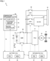
- Fig. 1 is a view schematically showing an overall configuration of a vehicle equipped with a heating system in accordance with an embodiment of the present disclosure.
- a vehicle 1 is an electrically powered vehicle equipped with a battery.
- vehicle 1 is a battery electric vehicle (BEV).
- BEV battery electric vehicle
- Vehicle 1 may be a plug-in hybrid electric vehicle (PHEV), or may be a fuel cell electric vehicle (FCEV).
- PHEV plug-in hybrid electric vehicle
- FCEV fuel cell electric vehicle
- Vehicle 1 may be a hybrid electric vehicle (HEV) that does not support plug-in charging.
- Vehicle 1 includes a battery 10, a monitoring unit 20, a system main relay (SMR) 30, a temperature management system 40, a battery ECU (Electronic Control Unit) 50, an inlet 61, an AC (alternate current)/DC (direct current) converter 62, a charge relay (CHR) 63, a power control unit (PCU) 71, a motor generator (MG) 72, a motive power transmission gear 73, drive wheels 74, and an integrated ECU 80, for example.
- SMR system main relay
- CHR charge relay
- PCU power control unit
- MG motor generator
- 74 motive power transmission gear 73
- drive wheels 74 and an integrated ECU 80, for example.
- Battery 10 is a battery assembly including a plurality of cells. Each cell is typically a liquid-type secondary battery (such as a lithium ion battery or a nickel hydride battery), but may be an all-solid-state battery. Battery 10 stores power for driving MG 72 and supplies the power to MG 72 through PCU 71. Further, when MG 72 generates power, battery 10 receives the generated power through PCU 71 and is charged.
- a liquid-type secondary battery such as a lithium ion battery or a nickel hydride battery
- Monitoring unit 20 includes various sensors for monitoring the state of battery 10. Specifically, monitoring unit 20 includes a voltage sensor, a current sensor, and a temperature sensor (neither is shown).
- the voltage sensor detects a voltage VB of battery 10 (each cell).
- the current sensor detects a current IB charged to or discharged from battery 10.
- the temperature sensor detects a temperature TB of battery 10 (at least one cell). Each sensor outputs a detection value thereof to battery ECU 50.
- SMR 30 is electrically connected to power lines connecting between battery 10 and PCU 71 and between battery 10 and CHR 63. SMR 30 is opened or closed according to a command from battery ECU 50. When SMR 30 is opened (turned off), battery 10 is electrically separated from PCU 71 and CHR 63. When SMR 30 is closed (turned on), battery 10 is electrically connected to PCU 71 and CHR 63.
- Temperature management system 40 is configured to adjust the temperature of battery 10 using a liquid heat medium, according to a control command from battery ECU 50. Temperature management system 40 corresponds to a "heating system" in accordance with the present disclosure. Temperature management system 40 includes a flow path 41, a coolant temperature sensor 42, an electric heater 43, and a heater control device 44, for example.
- Flow path 41 includes a circuit of a pipe through which the heat medium flows (circulates).
- flow path 41 is configured to cool battery 10 when battery 10 has a high temperature by causing the heat medium to flow through the circuit, and is also configured to perform heating (heat-up or warm-up) of battery 10 under an environment with a low temperature (for example, more than or equal to -20°C and less than 0°C) or a very low temperature (for example, less than -20°C).
- the heat medium is referred to as an "LLC" (Long Life Coolant).
- LLC Long Life Coolant
- Coolant temperature sensor 42 detects a temperature TC of the LLC (hereinafter referred to as a "coolant temperature”), and outputs a detection value thereof to battery ECU 50.
- Electric heater 43 is a PTC (Positive Temperature Coefficient) heater, for example, and heats the LLC. Thereby, battery 10 is heated.
- PTC Physical Temperature Coefficient
- Heater controller 44 controls electric heater 43 according to the control command from battery ECU 50. More specifically, in the present embodiment, battery ECU 50 provides heater controller 44 with a command about an upper limit temperature UL in an allowable temperature range of coolant temperature TC. Heater controller 44 controls electric heater 43 such that coolant temperature TC may approach upper limit temperature UL but not exceed upper limit temperature UL. Electric heater 43 may be controlled by switching electric heater 43 (turning on/off electric heater 43), or by adjusting an output from electric heater 43.
- Battery ECU 50 includes a processor 51 and a memory 52.
- Processor 51 is a computation processing unit such as a CPU (Central Processing Unit) or an MPU (Micro Processing Unit).
- Memory 52 is a storage device including a ROM (Read Only Memory) and a RAM (Random Access Memory).
- Memory 52 stores a system program including an OS (Operating System), a control program including computer-readable codes, and various parameters for managing battery 10.
- OS Operating System
- Processor 51 implements a variety of processing by reading the system program, the control program, and the parameters, loading them in memory 52, and executing them.
- battery ECU 50 performs "thermal deterioration evaluation” for quantitatively evaluating a degree of progress of thermal deterioration of the LLC. Further, battery ECU 50 performs "upper limit temperature control” for controlling the temperature of the LLC (coolant temperature TC) within an appropriate temperature range, according to the result of the thermal deterioration evaluation. The thermal deterioration evaluation and the upper limit temperature control will be described in detail later. It should be noted that battery ECU 50 corresponds to a "controller" in accordance with the present disclosure.
- Inlet 61 is configured such that, on the occasion of the plug-in charging, a charging connector (not shown) provided at a tip of a charging cable may be connected thereto with mechanical coupling. By connecting the charging connector to inlet 61, electrical connection between a charging facility (not shown) and vehicle 1 is secured. In this example, inlet 61 supports both AC charging (normal charging) and DC charging (fast charging).
- AC/DC converter 62 converts AC power supplied from an AC charging facility via the charging cable into DC power for charging battery 10.
- Vehicle 1 may include a DC/DC converter that supports DC charging (not shown), instead of or in addition to AC/DC converter 62.
- CHR 63 is connected to power lines that are charging paths from inlet 61, in series with SMR 30. CHR 63 is opened or closed according to a command from integrated ECU 80. When CHR 63 is closed and SMR 30 is closed, battery 10 can be charged using power from inlet 61.
- PCU 71 is electrically connected between SMR 30 and MG 72.
- PCU 71 includes a converter and an inverter (neither is shown), and drives MG 72 according to a command from integrated ECU 80.
- MG 72 is an AC rotating electric machine, and is, for example, a permanent magnet-type synchronous motor including a rotor having a permanent magnet embedded therein.
- the output torque of MG 72 is transmitted to drive wheels 74 through motive power transmission gear 73, to cause vehicle 1 to travel. Further, during a braking operation of vehicle 1, MG 72 can generate power using a rotational force of drive wheels 74.
- the power generated by MG 72 is converted by PCU 71 into charging power for battery 10.
- Integrated ECU 80 includes a processor 81 and a memory 82, as with battery ECU 50. Integrated ECU 80 performs a variety of control for controlling vehicle 1 in a desired state, based on signals received from the sensors and programs and maps stored in memory 82. For example, integrated ECU 80 controls power charged or discharged between battery 10 and PCU 71. Further, integrated ECU 80 controls the plug-in charging of vehicle 1 by communicating with the charging facility and controlling AC/DC converter 62 and CHR 63. Battery ECU 50 and integrated ECU 80 are configured such that they can communicate with each other. Battery ECU 50 and integrated ECU 80 may be integrally configured.
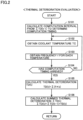
- Fig. 2 is a flowchart showing an example of a processing procedure for the thermal deterioration evaluation in the present embodiment.
- the processing shown in this flowchart is performed when a predetermined condition is satisfied (for example, for each predetermined cycle).
- each step is implemented by software processing by battery ECU 50, it may be implemented by hardware (electrical circuitry) arranged within battery ECU 50. The same applies to the upper limit temperature control described later (see Fig. 7 ). In the following, the step will be abbreviated as S.
- Battery ECU 50 calculates an index indicating a degree of progress of the thermal deterioration of the LLC in a period from a previous computation to a current computation. This index is denoted as a "thermal deterioration TD”.
- a currently calculated thermal deterioration is denoted as a "TD(t)”
- TD(t-1) a previously calculated thermal deterioration
- TD(t-2) a thermal deterioration calculated prior to the previously calculated thermal deterioration
- battery ECU 50 calculates an index indicating a degree of progress of the thermal deterioration of the LLC at present, by summing thermal deteriorations from the start (a first computation) to the present (the current computation) (that is, from TD(t0) to TD(t)). This index is denoted as a "summed thermal deterioration ⁇ TD". Summed thermal deterioration ⁇ TD has an initial value of 0. It should be noted that thermal deterioration TD corresponds to a "micro index" in accordance with the present disclosure, and summed thermal deterioration ⁇ TD corresponds to an "index" in accordance with the present disclosure.
- battery ECU 50 calculates computation timing of a current summed thermal deterioration ⁇ TD(t). More specifically, battery ECU 50 calculates a computation interval from the previous computation to the current computation, based on a previously summed thermal deterioration ⁇ TD(t-1). Then, battery ECU 50 determines a time when the computation interval has elapsed from a computation time of previous summed thermal deterioration ⁇ TD(t-1), as the computation timing of current summed thermal deterioration ⁇ TD(t).
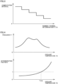
- Fig. 3 is a view showing an example of a technique of determining the computation interval for the summed thermal deterioration.
- the axis of abscissas represents previously summed thermal deterioration ⁇ TD(t-1).
- the axis of ordinate represents the computation interval from the previous computation to the current computation. As shown in Fig. 3 , the computation interval is determined be shorter, as previously summed thermal deterioration ⁇ TD(t-1) is larger (that is, as the thermal deterioration of the LLC progresses).
- Fig. 3 shows an example in which the computation interval decreases in a stepwise manner with an increase in summed thermal deterioration ⁇ TD.
- the computation interval may be shortened continuously (linearly or curvilinearly) with an increase in summed thermal deterioration ⁇ TD.
- the computation interval may be constant irrespective of summed thermal deterioration ⁇ TD.
- battery ECU 50 obtains coolant temperature TC from coolant temperature sensor 42. Then, battery ECU 50 calculates a frequency f of coolant temperature TC (for example, a frequency in each temperature range when coolant temperature TC is classified per degree Celsius) (S103).
- a frequency f of coolant temperature TC for example, a frequency in each temperature range when coolant temperature TC is classified per degree Celsius
- battery ECU 50 determines whether the computation timing calculated in S101 has arrived. When the computation timing has not arrived (NO in S104), battery ECU 50 returns the processing to S 102. Thereby, obtaining of coolant temperature TC and calculation of frequency f are performed again. When the computation timing has arrived (YES in S 104), battery ECU 50 advances the processing to S 105, to calculate current thermal deterioration TD(t).
- Fig. 4 is a conceptual diagram for illustrating a technique of calculating the thermal deterioration of the LLC (the processing in S105).
- the axis of abscissas represents coolant temperature TC.
- the upper axis of ordinate represents frequency f of coolant temperature TC, and the lower axis of ordinate represents a deterioration factor k.
- Frequency f of coolant temperature TC is obtained by the processing in S102 and S103.
- deterioration factor k indicates that the degree of progress of the thermal deterioration of the LLC is large.
- the higher coolant temperature TC is, the larger deterioration factor k is.
- Deterioration factor k is determined by a prior experiment, according to the specification of the LLC. In the present embodiment, deterioration factor k at an upper limit temperature Temp (described later) in a comparative example is determined as 1. In the case of TC ⁇ Temp, deterioration factor k is determined as k ⁇ 1. In the case of TC > Temp, deterioration factor k is determined as k > 1.
- Battery ECU 50 multiplies frequency f by deterioration factor k for each temperature range (for example, 1°C) of coolant temperature TC. Then, battery ECU 50 adds products (f ⁇ k) for all the temperature ranges of coolant temperature TC. Thereby, current thermal deterioration TD(t) is calculated (see equation (1)).
- TD t ⁇ f ⁇ k
- battery ECU 50 calculates currently summed thermal deterioration ⁇ TD(t) by adding current thermal deterioration TD(t) to previously summed thermal deterioration ⁇ TD(t-1) (see equation (2)).
- ⁇ TD t ⁇ TD t ⁇ 1 + TD t
- Fig. 5 is a view for illustrating how to determine an upper limit temperature in a comparative example.
- the axis of abscissas represents an elapsed time from an initial time t0 (for example, the time when the LLC was manufactured).
- the upper axis of ordinate represents coolant temperature TC, and the lower axis of ordinate represents summed thermal deterioration ⁇ TD. The same applies to Fig. 6 described later.
- upper limit temperature UL that allows change of coolant temperature TC is set to Temp.
- upper limit temperature UL is set to be variable. More specifically, upper limit temperature UL is set to be lower, as the thermal deterioration of the LLC progresses.
- Fig. 6 is a view for illustrating a summary of the upper limit temperature control in the present embodiment.
- upper limit temperature UL is set to one of three types: Tlim, T1, and T2. These three temperatures have the relation of Tlim > T1 > T2, and they are all higher than upper limit temperature Temp in the comparative example.
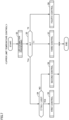
- Fig. 7 is a flowchart showing an example of a processing procedure for the upper limit temperature control in the present embodiment.
- battery ECU 50 sets upper limit temperature UL of the LLC to Tlim, which is the highest, for example.
- battery ECU 50 performs life estimation processing for estimating the life of the LLC.
- the life of the LLC means a period in which the LLC can secure the electrical insulation property required for the LLC.
- five lines are used for the life estimation processing.
- the five lines include first estimation line L1 to fourth estimation line L4, in addition to reference line L0 as in the comparative example. These lines will be described using the following flowcharts and time charts.
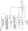
- Fig. 8 is a flowchart showing an example of a processing procedure for the life estimation processing.
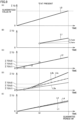
- Fig. 9 is a time chart for illustrating an example of the life estimation processing.
- the axis of abscissas represents an elapsed time from initial time t0.
- the axis of ordinate represents summed thermal deterioration ⁇ TD.
- reference line L0 (see Fig. 9(A) ) is the same as L0 in the comparative example. As described above, reference line L0 is determined such that summed thermal deterioration ⁇ TD may reach guaranteed value W at the time when guarantee period tW for the LLC has elapsed.
- the processing in S201 to S204 is processing for calculating first estimation line L1.
- battery ECU 50 obtains regional information of vehicle 1.
- the regional information is information indicating the location of vehicle 1, and is typically positional information obtained by a GPS (Global Positioning System). However, the regional information may be fixed information such as destination information of vehicle 1.
- battery ECU 50 calculates an environment estimation line Llenv based on the regional information.
- Environment estimation line Llenv is an estimation line indicating an increase in the summed thermal deterioration when a typical temperature load at the location of vehicle 1 is applied to the LLC, and is determined according to past outside air temperatures in the region.
- battery ECU 50 calculates a use estimation line Lluse based on the regional information (S203).
- Use estimation line Lluse is an estimation line indicating an increase in the summed thermal deterioration when a typical use load at the location of vehicle 1 is applied to the LLC, and is determined according to ordinary travelling manners (such as a travelling speed, a gradient, and a travelling time) of the vehicle in the region.
- Each of environment estimation line Llenv and use estimation line Lluse is prepared beforehand for each region and is stored in memory 52 of battery ECU 50.
- battery ECU 50 calculates first estimation line L1 based on environment estimation line Llenv and use estimation line Lluse. More specifically, first estimation line L1 is calculated by adding environment estimation line Llenv and use estimation line Lluse (adding estimated values at an identical time) (see equation (3)), as shown in Fig. 9(B) .
- L1 L1env + L1use
- second estimation line L2 that is a regression line of summed thermal deterioration ⁇ TD over the entire period from initial time t0 to the present.
- second estimation line L2 is calculated by the least squares method, for example, to provide a good approximation for four summed thermal deteriorations 0, ⁇ TD(t1), ⁇ TD(t2), and ⁇ TD(t3) from initial time t0 to the present.
- battery ECU 50 calculates third estimation line L3 based on latest two summed thermal deteriorations ⁇ TD, that is, previously summed thermal deterioration ⁇ TD(t-1) and currently summed thermal deterioration ⁇ TD(t). More specifically, current third estimation line L3 is a straight line L3c connecting previously summed thermal deterioration ⁇ TD(t-1) and currently summed thermal deterioration ⁇ TD(t). Fig. 9(D) also shows past straight lines L3a and L3b.
- third estimation line L3 how the LLC has been used lately can be reflected in life estimation, when compared with a case where only second estimation line L2 is calculated. For example, when summed thermal deterioration ⁇ TD increases quickly, upper limit temperature UL can be lowered quickly (the details will be described later).
- battery ECU 50 calculates fourth estimation line L4 by combining the first estimation line L1 and second estimation line L2 with a ratio of j:(1-j) (0 ⁇ j ⁇ 1), respectively (see equation (4)).
- L4 L1 ⁇ j + L2 ⁇ 1 ⁇ j
- Fig. 10 is a view showing an example of a technique of determining ratio j.
- the axis of abscissas represents previously summed thermal deterioration ⁇ TD(t-1).
- the axis of ordinate represents ratio j.
- ratio j is determined to be lower, as previously summed thermal deterioration ⁇ TD(t-1) is larger (that is, as the thermal deterioration of the LLC progresses).
- fourth estimation line L4 is calculated mainly based on the regional information of vehicle 1 that is data prepared beforehand.
- ratio j becomes lower as summed thermal deterioration ⁇ TD becomes larger (as the thermal deterioration of the LLC progresses)
- the contribution of first estimation line L1 decreases, and the contribution of second estimation line L2 increases.
- fourth estimation line L4 is calculated mainly based on summed thermal deterioration ⁇ TD of the LLC over the entire period, in which an actual status of use of vehicle 1 is reflected.
- Fig. 10 shows an example in which ratio j decreases in a stepwise manner with an increase in summed thermal deterioration ⁇ TD.
- ratio j may decrease continuously (linearly or curvilinearly) with an increase in summed thermal deterioration ⁇ TD.
- ratio j may be constant irrespective of summed thermal deterioration ⁇ TD.
- processing for calculating first estimation line L1 to the processing for calculating fourth estimation line L4 respectively correspond to “first life estimation processing” to “fourth life estimation processing” in accordance with the present disclosure.
- battery ECU 50 advances the processing to S3, to determine to which of Tlim, T1, and T2 upper limit temperature UL of the LLC is set.
- UL Tlim (Tlim in S3)
- battery ECU 50 determines whether current summed thermal deterioration ⁇ TD(t) obtained by the thermal deterioration evaluation (see Fig. 2 ) is lower than a reference line L0(t) (S4).
- Fig. 11 is a view for illustrating determination processing in S4.
- battery ECU 50 When current summed thermal deterioration ⁇ TD(t) is lower than reference line L0(t) as shown in Fig. 11(A) (YES in S4), battery ECU 50 performs first control (S5). In contrast, when current summed thermal deterioration ⁇ TD(t) is higher than or equal to reference line L0(t) as shown in Fig. 11(B) (NO in S4), battery ECU 50 performs second control (S6).
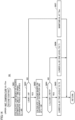
- Fig. 12 is a flowchart showing an example of a processing procedure for the first control.
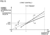
- Fig. 13 is a time chart for illustrating the first control.
- upper limit temperature UL remains unchanged at Tlim.
- the estimated value based on fourth estimation line L4 is a combination of the data prepared beforehand (L1) and data in which the actual status of use of vehicle 1 is reflected (L2), with ratio j.
- battery ECU 50 determines whether L4(tW) at the time when the guarantee period has elapsed is higher than or equal to guaranteed value W (in other words, whether the life of the LLC is longer than the guarantee period). In the case of L4(tW) ⁇ W (YES in S502), battery ECU 50 advances the processing to S503. On the other hand, in the case of L4(tW) ⁇ W (NO in S502), summed thermal deterioration ⁇ TD is less likely to exceed guaranteed value W even when the guarantee period has elapsed, and thus battery ECU 50 maintains upper limit temperature UL of the LLC at Tlim (S509).
- battery ECU 50 calculates L3(tW) that is an estimated value based on the third estimation line at the time when the guarantee period has elapsed.
- the estimated value based on third estimation line L3 is for reflecting how the LLC has been used lately in the life estimation.
- battery ECU 50 determines whether L3(tW) at the time when the guarantee period has elapsed is higher than or equal to guaranteed value W. In the case of L3(tW) ⁇ W (YES in S504), battery ECU 50 advances the processing to S505. On the other hand, in the case of L3(tW) ⁇ W (NO in S504), battery ECU 50 maintains upper limit temperature UL of the LLC at Tlim (S509).
- battery ECU 50 calculates a deviation rate (error rate) ⁇ (t) of summed thermal deterioration ⁇ TD(t) with respect to reference line L0(t) at present (see equation (5)).
- the absolute value of) deviation rate ⁇ represents the magnitude of deviation of summed thermal deterioration ⁇ TD(t) from reference line L0(t).
- deviation rate ⁇ a difference between reference line L0(t) and summed thermal deterioration ⁇ TD(t) may be used.
- ⁇ t ⁇ TD t / L0 t
- battery ECU 50 determines whether the absolute value of deviation rate ⁇ (t) at present is lower than or equal to a predetermined threshold TH. In the case of
- battery ECU 50 provides a notification (proposal) to a user, via an HMI (Human Machine Interface) not shown, to reduce use manners of vehicle 1 that may cause the thermal deterioration of the LLC (specifically, frequency and/or time of DC charging), as much as possible.
- HMI Human Machine Interface
- upper limit temperature UL of the LLC is not lowered, although summed thermal deterioration ⁇ TD may exceed guaranteed value W by the time when the guarantee period has elapsed, if things continue as they are.
- current summed thermal deterioration ⁇ TD(t) exceeds reference line L0(t) (NO in S4 in Fig. 7 )
- the second control described below is performed instead of the first control, and upper limit temperature UL of the LLC is lowered.
- Fig. 14 is a flowchart showing an example of a processing procedure for the second control.
- Fig. 15 is a time chart for illustrating the second control.
- upper limit temperature UL can be lowered from Tlim to T1 or T2.
- first reference value REF1 to third reference value REF3 are determined. These three reference values have a magnitude relation of REF1 > REF2 > REF3, and they are all lower than guaranteed value W.
- battery ECU 50 determines whether L4(tW) at the time when the guarantee period has elapsed is higher than or equal to guaranteed value W. In the case of L4(tW) ⁇ W (YES in S602), summed thermal deterioration ⁇ TD may exceed guaranteed value W by the time when the guarantee period has elapsed, if things continue as they are. Further, since the second control is performed, it means that current summed thermal deterioration ⁇ TD(t) is higher than or equal to reference line L0(t). Therefore, battery ECU 50 advances the processing to S603, to lower upper limit temperature UL of the LLC.
- battery ECU 50 calculates Llenv(tW) that is an estimated value based on the environment estimation line at the time when the guarantee period has elapsed.
- Llenv(tW) is an estimated value of summed thermal deterioration ⁇ TD when the typical temperature load at the location of vehicle 1 continues to be applied to the LLC until the guarantee period elapses.
- Thermal deterioration due to the typical use load at the location of vehicle 1 is not incorporated into L1env(tW). That is, Llenv(tW) indicates a degree of progress of the thermal deterioration of the LLC when vehicle 1 is left unused until the guarantee period elapses.
- battery ECU 50 determines whether Llenv(tW) at the time when the guarantee period has elapsed is higher than or equal to second reference value REF2. In the case of Llenv(tW) ⁇ REF2 (YES in S604), battery ECU 50 lowers upper limit temperature UL of the LLC by two levels and sets it to T2 (S605). This can prevent summed thermal deterioration ⁇ TD from reaching guaranteed value W despite that vehicle 1 is merely left unused until the guarantee period elapses.
- battery ECU 50 lowers upper limit temperature UL of the LLC by one level and sets it to T1 (S606), in order to minimize degradation of the charging/discharging performance of battery 10 (to mitigate the effect on the charging/discharging performance).
- the estimated value based on the third estimation line is not used. This is because, since the thermal deterioration has already progressed more than the reference ( ⁇ TD(t) ⁇ L0(t)) up to the present time when the second control is performed, upper limit temperature UL of the LLC is lowered irrespective of how the LLC has been used lately. That is, in the second control, priority is given to suppression of the deterioration of the LLC, when compared with the first control.
- upper limit temperature UL of the LLC when upper limit temperature UL of the LLC is lowered, the frequency at which DC charging is allowed (the number of times of charging allowed in a predetermined period) may be reduced in addition thereto.
- Fig. 16 is a flowchart showing an example of a processing procedure for the third control.
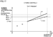
- Fig. 17 is a time chart for illustrating the third control.
- the third control is performed when upper limit temperature UL of the LLC is T1.
- upper limit temperature UL may be maintained at T1
- upper limit temperature UL may be raised to Tlim
- upper limit temperature UL may be lowered to T2.
- battery ECU 50 calculates L4(tW) that is an estimated value based on the fourth estimation line at the time when the guarantee period has elapsed. Furthermore, battery ECU 50 calculates Llenv(tW) that is an estimated value based on the environment estimation line at the time when the guarantee period has elapsed (S702).
- battery ECU 50 determines whether L4(tW) is higher than or equal to guaranteed value W and Llenv(tW) is higher than or equal to second reference value REF2. In the case of L4(tW) ⁇ W and Llenv(tW) ⁇ REF2 (YES in S703), battery ECU 50 lowers upper limit temperature UL of the LLC and sets it to T2 (S704). In the case of L4(tW) ⁇ W or Llenv(tW) ⁇ REF2 (NO in S703), battery ECU 50 advances the processing to S705.
- battery ECU 50 determines whether Llenv(tW) is higher than or equal to first reference value REF1. In the case of Llenv(tW) ⁇ REF1 (YES in S705), battery ECU 50 maintains upper limit temperature UL of the LLC at T1 (S706). On the other hand, in the case pf Llenv(tW) ⁇ REF1 (NO in S705), battery ECU 50 raises upper limit temperature UL of the LLC and sets it to Tlim (S707).
- Fig. 18 is a flowchart showing an example of a processing procedure for the fourth control.
- Fig. 19 is a time chart for illustrating the fourth control.
- the fourth control is performed when upper limit temperature UL is T2.
- upper limit temperature UL is maintained at T2, or is raised by one level to T1.
- battery ECU 50 calculates L4(tW) that is an estimated value based on the fourth estimation line at the time when the guarantee period has elapsed.
- battery ECU 50 determines whether L4(tW) is higher than or equal to guaranteed value W. In the case of L4(tW) ⁇ W (YES in S802), battery ECU 50 advances the processing to S803. On the other hand, in the case of L4(tW) ⁇ W (NO in S802), battery ECU 50 maintains upper limit temperature UL of the LLC at T2 (S806).
- battery ECU 50 determines whether Llenv(tW) is lower than third reference value REF 3. In the case of Llenv(tW) ⁇ REF3 (YES in S804), battery ECU 50 raises upper limit temperature UL of the LLC and sets it to T1 (S805). On the other hand, in the case of Llenv(tW) ⁇ REF3 (NO in S804), battery ECU 50 maintains upper limit temperature UL of the LLC at T2 (S806).
- the heating performance of the heat medium can be improved by setting upper limit temperature UL to Tlim (the first control).
- the thermal deterioration of the heat medium progresses (NO in S4)
- further progress of the thermal deterioration of the heat medium can be suppressed by setting upper limit temperature UL to T1 or T2 (the second control to the fourth control). Therefore, according to the present embodiment, it is possible to secure the performance and suppress the deterioration of the heat medium.
Landscapes
- Engineering & Computer Science (AREA)
- Manufacturing & Machinery (AREA)
- Chemical & Material Sciences (AREA)
- Chemical Kinetics & Catalysis (AREA)
- Electrochemistry (AREA)
- General Chemical & Material Sciences (AREA)
- Mechanical Engineering (AREA)
- Life Sciences & Earth Sciences (AREA)
- Sustainable Development (AREA)
- Sustainable Energy (AREA)
- Power Engineering (AREA)
- Transportation (AREA)
- Automation & Control Theory (AREA)
- Microelectronics & Electronic Packaging (AREA)
- Physics & Mathematics (AREA)
- Thermal Sciences (AREA)
- Electric Propulsion And Braking For Vehicles (AREA)
- Secondary Cells (AREA)
- Charge And Discharge Circuits For Batteries Or The Like (AREA)
Abstract
A temperature management system (40) heats a battery (10) using a liquid heat medium (an LLC). A battery ECU (50), which is a controller for the temperature management system (40), includes a processor (51) that calculates an upper limit temperature of the LLC during heating of the battery (10). The processor (51) lowers the upper limit temperature, as thermal deterioration of the LLC progresses.
Description
- This nonprovisional application is based on
Japanese Patent Application No. 2023-083685 filed on May 22, 2023 - The present disclosure relates to a controller for a heating system, a vehicle including the same, and a method for managing a heat medium, and more specifically, to a technique of heating a battery by heat exchange between a liquid heat medium and the battery.
-
Japanese Patent Laying-Open No. 2016-112933 - Generally, under a low temperature environment, charging/discharging performance of a battery (power that a battery can charge/discharge) may be degraded. Accordingly, an electrically powered vehicle is equipped with a heating system that performs heating (also referred to as heat-up or warm-up) of a battery by heat exchange between the battery and a liquid heat medium. In particular, a heat medium (coolant) for a vehicle has a high electrical insulation property in case of leakage.
- The present inventors focused attention to that the following problem may occur in such a heating system. If the temperature of the heat medium is raised excessively to heat the battery, the heat medium may be thermally deteriorated and the electrical insulation property of the heat medium may be degraded. Therefore, it is desirable to suppress thermal deterioration of the heat medium while securing heating performance of the heat medium (charging/discharging performance of the battery achieved thereby), in other words, to secure the performance and suppress the deterioration of the heat medium.
- The present disclosure has been made to solve the aforementioned problem, and one of the objects of the present disclosure is to secure performance and suppress deterioration of a heat medium.
- (1) In a controller for a heating system in accordance with an aspect of the present disclosure, the heating system heats a battery using a liquid heat medium. The controller includes a processor that calculates an upper limit temperature of the heat medium during heating of the battery. The processor lowers the upper limit temperature, as thermal deterioration of the heat medium progresses.
In the configuration described above in (1), when the thermal deterioration of the heat medium does not progress, heating performance of the heat medium can be improved by raising the upper limit temperature. On the other hand, when the thermal deterioration of the heat medium progresses, further progress of the thermal deterioration of the heat medium can be suppressed by lowering the upper limit temperature. Therefore, it is possible to secure the performance and suppress the deterioration of the heat medium. - (2) The processor calculates an index indicating a degree of progress of the thermal deterioration of the heat medium based on a temperature of the heat medium, estimates a life of the heat medium based on the index, and lowers the upper limit temperature when the life is estimated to be shorter than a predetermined period, when compared with a case where the life is estimated to be longer than the predetermined period.
According to the configuration described above in (2), since the upper limit temperature is lowered when the life is estimated to be shorter than the predetermined period, the thermal deterioration of the heat medium is suppressed. Thereby, the life of the heat medium can be longer than the predetermined period. - (3) The processor repeatedly performs computation processing for calculating the index. The computation processing includes processing of calculating, based on the temperature of the heat medium in a period from a previous computation to a current computation, a micro index indicating a degree of progress of the thermal deterioration of the heat medium in the period, and calculating the index up to the current computation, by adding the micro index in the period, to the index up to the previous computation.
- (4) The processor calculates the micro index based on a product of a frequency of the temperature of the heat medium in the period and a coefficient determined for each temperature of the heat medium.
According to the configuration described above in (3) and (4), the index can be calculated with high accuracy (that is, the degree of progress of the thermal deterioration of the heat medium can be evaluated with high accuracy). - (5) The processor shortens a computation interval of the computation processing, as the index indicates that the thermal deterioration of the heat medium progresses.
In the configuration described above in (5), in a stage where the thermal deterioration of the heat medium does not progress, a computation load on the processor for calculating the index can be reduced by lengthening the computation interval. On the other hand, by shortening the computation interval as the thermal deterioration of the heat medium progresses, the upper limit temperature can be adjusted based on the accurate index. As a result, excessive thermal deterioration of the heat medium can be suppressed more reliably. - (6) The processor performs first life estimation processing. The first life estimation processing includes processing of calculating the index based on information of a region where the heating system is used.
- (7) The first life estimation processing includes processing of calculating the index when a temperature load in the region where the heating system is used is applied to the heat medium.
- (8) The first life estimation processing includes processing of calculating the index when a use load in the region where the heating system is used is applied to the heat medium.
- (9) The processor performs second life estimation processing. The second life estimation processing includes processing of estimating the life by regression analysis of the index over an entire period.
- (10) The processor performs third life estimation processing. The third life estimation processing includes processing of estimating the life by regression analysis of a portion of the index over an entire period, the portion including the index up to the current computation.
- (11) The processor performs fourth life estimation processing. The fourth life estimation processing includes processing of combining a result of first life estimation processing and a result of second life estimation processing. The first life estimation processing includes processing of calculating the index based on information of a region where the heating system is used. The second life estimation processing includes processing of estimating the life by regression analysis of the index over an entire period.
- (12) The processor increases a ratio of the result of the second life estimation processing used for the fourth life estimation processing, as the index indicates that the thermal deterioration of the heat medium progresses.
According to the configuration described above in (6) to (12), the life of the heat medium can be estimated with high accuracy, according to the region (the first life estimation processing), an actual status of use over the entire period (the second life estimation processing), the latest actual status of use (the third life estimation processing), both the region and the status of use (the fourth life estimation processing), and the like. - (13) The predetermined period is a guarantee period for the heat medium.
According to the configuration described above in (13), the life of the heat medium can be longer than the guarantee period for the heat medium. - (14) A vehicle in accordance with another aspect of the present disclosure includes the controller, and the heating system.
- (15) A method for managing a heat medium in accordance with another aspect of the present disclosure includes calculating an upper limit temperature of a liquid heat medium, and heating a battery using the heat medium. The calculating includes lowering the upper limit temperature, as thermal deterioration of the heat medium progresses.
- According to the configuration described above in (14) and the method described above in (15), it is possible to secure the performance and suppress the deterioration of the heat medium, as with the configuration described above in (1).
- The foregoing and other objects, features, aspects, and advantages of the present disclosure will become more apparent from the following detailed description of the present disclosure when taken in conjunction with the accompanying drawings.
-
-
Fig. 1 is a view schematically showing an overall configuration of a vehicle equipped with a heating system in accordance with an embodiment of the present disclosure. -
Fig. 2 is a flowchart showing an example of a processing procedure for thermal deterioration evaluation in the present embodiment. -
Fig. 3 is a view showing an example of a technique of determining a computation interval for summed thermal deterioration. -
Fig. 4 is a conceptual diagram for illustrating a technique of calculating thermal deterioration of a heat medium. -
Fig. 5 is a view for illustrating how to determine an upper limit temperature in a comparative example. -
Fig. 6 is a view for illustrating a summary of upper limit temperature control in the present embodiment. -
Fig. 7 is a flowchart showing an example of a processing procedure for the upper limit temperature control in the present embodiment. -
Fig. 8 is a flowchart showing an example of a processing procedure for life estimation processing. -
Fig. 9 is a time chart for illustrating an example of the life estimation processing. -
Fig. 10 is a view showing an example of a technique of determining a ratio. -
Fig. 11 is a view for illustrating determination processing in step 4. -
Fig. 12 is a flowchart showing an example of a processing procedure for first control. -
Fig. 13 is a time chart for illustrating the first control. -
Fig. 14 is a flowchart showing an example of a processing procedure for second control. -
Fig. 15 is a time chart for illustrating the second control. -
Fig. 16 is a flowchart showing an example of a processing procedure for third control. -
Fig. 17 is a time chart for illustrating the third control. -
Fig. 18 is a flowchart showing an example of a processing procedure for fourth control. -
Fig. 19 is a time chart for illustrating the fourth control. - Hereinafter, an embodiment of the present disclosure will be described in detail with reference to the drawings. It should be noted that identical or corresponding parts in the drawings will be designated by the same reference numerals, and the description thereof will not be repeated.
- In the following embodiment, a configuration in which a heating system (and a controller therefor) in accordance with the present disclosure is mounted in a vehicle will be described as an example. However, the application of the heating system in accordance with the present disclosure is not limited to an application for vehicles. The heating system in accordance with the present disclosure is applicable to any application (for example, stationary application).
-
Fig. 1 is a view schematically showing an overall configuration of a vehicle equipped with a heating system in accordance with an embodiment of the present disclosure. Avehicle 1 is an electrically powered vehicle equipped with a battery. In this example,vehicle 1 is a battery electric vehicle (BEV).Vehicle 1 may be a plug-in hybrid electric vehicle (PHEV), or may be a fuel cell electric vehicle (FCEV).Vehicle 1 may be a hybrid electric vehicle (HEV) that does not support plug-in charging. -
Vehicle 1 includes abattery 10, amonitoring unit 20, a system main relay (SMR) 30, atemperature management system 40, a battery ECU (Electronic Control Unit) 50, aninlet 61, an AC (alternate current)/DC (direct current)converter 62, a charge relay (CHR) 63, a power control unit (PCU) 71, a motor generator (MG) 72, a motivepower transmission gear 73,drive wheels 74, and an integratedECU 80, for example. -
Battery 10 is a battery assembly including a plurality of cells. Each cell is typically a liquid-type secondary battery (such as a lithium ion battery or a nickel hydride battery), but may be an all-solid-state battery.Battery 10 stores power for drivingMG 72 and supplies the power toMG 72 throughPCU 71. Further, whenMG 72 generates power,battery 10 receives the generated power throughPCU 71 and is charged. - Monitoring
unit 20 includes various sensors for monitoring the state ofbattery 10. Specifically, monitoringunit 20 includes a voltage sensor, a current sensor, and a temperature sensor (neither is shown). The voltage sensor detects a voltage VB of battery 10 (each cell). The current sensor detects a current IB charged to or discharged frombattery 10. The temperature sensor detects a temperature TB of battery 10 (at least one cell). Each sensor outputs a detection value thereof tobattery ECU 50. -
SMR 30 is electrically connected to power lines connecting betweenbattery 10 andPCU 71 and betweenbattery 10 andCHR 63.SMR 30 is opened or closed according to a command frombattery ECU 50. WhenSMR 30 is opened (turned off),battery 10 is electrically separated fromPCU 71 andCHR 63. WhenSMR 30 is closed (turned on),battery 10 is electrically connected toPCU 71 andCHR 63. -
Temperature management system 40 is configured to adjust the temperature ofbattery 10 using a liquid heat medium, according to a control command frombattery ECU 50.Temperature management system 40 corresponds to a "heating system" in accordance with the present disclosure.Temperature management system 40 includes aflow path 41, acoolant temperature sensor 42, anelectric heater 43, and aheater control device 44, for example. - Flow
path 41 includes a circuit of a pipe through which the heat medium flows (circulates). In the present embodiment, flowpath 41 is configured to coolbattery 10 whenbattery 10 has a high temperature by causing the heat medium to flow through the circuit, and is also configured to perform heating (heat-up or warm-up) ofbattery 10 under an environment with a low temperature (for example, more than or equal to -20°C and less than 0°C) or a very low temperature (for example, less than -20°C). In the following, the heat medium is referred to as an "LLC" (Long Life Coolant). The LLC has a high electrical insulation property in case of leakage. -
Coolant temperature sensor 42 detects a temperature TC of the LLC (hereinafter referred to as a "coolant temperature"), and outputs a detection value thereof tobattery ECU 50. -
Electric heater 43 is a PTC (Positive Temperature Coefficient) heater, for example, and heats the LLC. Thereby,battery 10 is heated. -
Heater controller 44 controlselectric heater 43 according to the control command frombattery ECU 50. More specifically, in the present embodiment,battery ECU 50 providesheater controller 44 with a command about an upper limit temperature UL in an allowable temperature range of coolant temperature TC.Heater controller 44 controlselectric heater 43 such that coolant temperature TC may approach upper limit temperature UL but not exceed upper limit temperature UL.Electric heater 43 may be controlled by switching electric heater 43 (turning on/off electric heater 43), or by adjusting an output fromelectric heater 43. -
Battery ECU 50 includes aprocessor 51 and amemory 52.Processor 51 is a computation processing unit such as a CPU (Central Processing Unit) or an MPU (Micro Processing Unit).Memory 52 is a storage device including a ROM (Read Only Memory) and a RAM (Random Access Memory).Memory 52 stores a system program including an OS (Operating System), a control program including computer-readable codes, and various parameters for managingbattery 10.Processor 51 implements a variety of processing by reading the system program, the control program, and the parameters, loading them inmemory 52, and executing them. - In the present embodiment,
battery ECU 50 performs "thermal deterioration evaluation" for quantitatively evaluating a degree of progress of thermal deterioration of the LLC. Further,battery ECU 50 performs "upper limit temperature control" for controlling the temperature of the LLC (coolant temperature TC) within an appropriate temperature range, according to the result of the thermal deterioration evaluation. The thermal deterioration evaluation and the upper limit temperature control will be described in detail later. It should be noted thatbattery ECU 50 corresponds to a "controller" in accordance with the present disclosure. -
Inlet 61 is configured such that, on the occasion of the plug-in charging, a charging connector (not shown) provided at a tip of a charging cable may be connected thereto with mechanical coupling. By connecting the charging connector toinlet 61, electrical connection between a charging facility (not shown) andvehicle 1 is secured. In this example,inlet 61 supports both AC charging (normal charging) and DC charging (fast charging). - AC/
DC converter 62 converts AC power supplied from an AC charging facility via the charging cable into DC power for chargingbattery 10.Vehicle 1 may include a DC/DC converter that supports DC charging (not shown), instead of or in addition to AC/DC converter 62. -
CHR 63 is connected to power lines that are charging paths frominlet 61, in series withSMR 30.CHR 63 is opened or closed according to a command fromintegrated ECU 80. WhenCHR 63 is closed andSMR 30 is closed,battery 10 can be charged using power frominlet 61. -
PCU 71 is electrically connected betweenSMR 30 andMG 72.PCU 71 includes a converter and an inverter (neither is shown), and drivesMG 72 according to a command fromintegrated ECU 80. -
MG 72 is an AC rotating electric machine, and is, for example, a permanent magnet-type synchronous motor including a rotor having a permanent magnet embedded therein. The output torque ofMG 72 is transmitted to drivewheels 74 through motivepower transmission gear 73, to causevehicle 1 to travel. Further, during a braking operation ofvehicle 1,MG 72 can generate power using a rotational force ofdrive wheels 74. The power generated byMG 72 is converted byPCU 71 into charging power forbattery 10. -
Integrated ECU 80 includes aprocessor 81 and amemory 82, as withbattery ECU 50.Integrated ECU 80 performs a variety of control for controllingvehicle 1 in a desired state, based on signals received from the sensors and programs and maps stored inmemory 82. For example, integratedECU 80 controls power charged or discharged betweenbattery 10 andPCU 71. Further, integratedECU 80 controls the plug-in charging ofvehicle 1 by communicating with the charging facility and controlling AC/DC converter 62 andCHR 63.Battery ECU 50 andintegrated ECU 80 are configured such that they can communicate with each other.Battery ECU 50 andintegrated ECU 80 may be integrally configured. -
Fig. 2 is a flowchart showing an example of a processing procedure for the thermal deterioration evaluation in the present embodiment. The processing shown in this flowchart is performed when a predetermined condition is satisfied (for example, for each predetermined cycle). Although each step is implemented by software processing bybattery ECU 50, it may be implemented by hardware (electrical circuitry) arranged withinbattery ECU 50. The same applies to the upper limit temperature control described later (seeFig. 7 ). In the following, the step will be abbreviated as S. - A summary of the thermal deterioration evaluation will be described.
Battery ECU 50 calculates an index indicating a degree of progress of the thermal deterioration of the LLC in a period from a previous computation to a current computation. This index is denoted as a "thermal deterioration TD". A currently calculated thermal deterioration is denoted as a "TD(t)", a previously calculated thermal deterioration is denoted as a "TD(t-1)", and a thermal deterioration calculated prior to the previously calculated thermal deterioration is denoted as a "TD(t-2)". The same applies to thermal deteriorations prior to that. Furthermore,battery ECU 50 calculates an index indicating a degree of progress of the thermal deterioration of the LLC at present, by summing thermal deteriorations from the start (a first computation) to the present (the current computation) (that is, from TD(t0) to TD(t)). This index is denoted as a "summed thermal deterioration ΣTD". Summed thermal deterioration ΣTD has an initial value of 0. It should be noted that thermal deterioration TD corresponds to a "micro index" in accordance with the present disclosure, and summed thermal deterioration ΣTD corresponds to an "index" in accordance with the present disclosure. - In S101,
battery ECU 50 calculates computation timing of a current summed thermal deterioration ΣTD(t). More specifically,battery ECU 50 calculates a computation interval from the previous computation to the current computation, based on a previously summed thermal deterioration ΣTD(t-1). Then,battery ECU 50 determines a time when the computation interval has elapsed from a computation time of previous summed thermal deterioration ΣTD(t-1), as the computation timing of current summed thermal deterioration ΣTD(t). -
Fig. 3 is a view showing an example of a technique of determining the computation interval for the summed thermal deterioration. The axis of abscissas represents previously summed thermal deterioration ΣTD(t-1). The axis of ordinate represents the computation interval from the previous computation to the current computation. As shown inFig. 3 , the computation interval is determined be shorter, as previously summed thermal deterioration ΣTD(t-1) is larger (that is, as the thermal deterioration of the LLC progresses). - In a stage where summed thermal deterioration ΣTD is small (in a case where the thermal deterioration of the LLC does not progress much), a computation load on
battery ECU 50 consumed for the thermal deterioration evaluation can be reduced by lengthening the computation interval. On the other hand, by shortening the computation interval as summed thermal deterioration ΣTD becomes larger (as the thermal deterioration of the LLC progresses), the upper limit temperature control described later can be performed based on accurate summed thermal deterioration ΣTD. As a result, excessive thermal deterioration of the LLC can be suppressed more reliably. - It should be noted that
Fig. 3 shows an example in which the computation interval decreases in a stepwise manner with an increase in summed thermal deterioration ΣTD. However, the computation interval may be shortened continuously (linearly or curvilinearly) with an increase in summed thermal deterioration ΣTD. Alternatively, the computation interval may be constant irrespective of summed thermal deterioration ΣTD. - Returning to
Fig. 2 , in S102,battery ECU 50 obtains coolant temperature TC fromcoolant temperature sensor 42. Then,battery ECU 50 calculates a frequency f of coolant temperature TC (for example, a frequency in each temperature range when coolant temperature TC is classified per degree Celsius) (S103). - In S104,
battery ECU 50 determines whether the computation timing calculated in S101 has arrived. When the computation timing has not arrived (NO in S104),battery ECU 50 returns the processing toS 102. Thereby, obtaining of coolant temperature TC and calculation of frequency f are performed again. When the computation timing has arrived (YES in S 104),battery ECU 50 advances the processing toS 105, to calculate current thermal deterioration TD(t). -
Fig. 4 is a conceptual diagram for illustrating a technique of calculating the thermal deterioration of the LLC (the processing in S105). The axis of abscissas represents coolant temperature TC. The upper axis of ordinate represents frequency f of coolant temperature TC, and the lower axis of ordinate represents a deterioration factor k. Frequency f of coolant temperature TC is obtained by the processing in S102 and S103. - Large deterioration factor k indicates that the degree of progress of the thermal deterioration of the LLC is large. The higher coolant temperature TC is, the larger deterioration factor k is. Deterioration factor k is determined by a prior experiment, according to the specification of the LLC. In the present embodiment, deterioration factor k at an upper limit temperature Temp (described later) in a comparative example is determined as 1. In the case of TC < Temp, deterioration factor k is determined as k < 1. In the case of TC > Temp, deterioration factor k is determined as k > 1.
-
Battery ECU 50 multiplies frequency f by deterioration factor k for each temperature range (for example, 1°C) of coolant temperature TC. Then,battery ECU 50 adds products (f×k) for all the temperature ranges of coolant temperature TC. Thereby, current thermal deterioration TD(t) is calculated (see equation (1)).
- Returning to
Fig. 2 , in S106,battery ECU 50 calculates currently summed thermal deterioration ΣTD(t) by adding current thermal deterioration TD(t) to previously summed thermal deterioration ΣTD(t-1) (see equation (2)).
- In order to clarify the feature of the upper limit temperature control in the present embodiment, temperature control in a comparative example will be described first.
-
Fig. 5 is a view for illustrating how to determine an upper limit temperature in a comparative example. The axis of abscissas represents an elapsed time from an initial time t0 (for example, the time when the LLC was manufactured). The upper axis of ordinate represents coolant temperature TC, and the lower axis of ordinate represents summed thermal deterioration ΣTD. The same applies toFig. 6 described later. - In the comparative example, upper limit temperature UL that allows change of coolant temperature TC is set to Temp. In the comparative example, upper limit temperature UL = Temp is maintained to be constant over the entire period. Temp is determined such that summed thermal deterioration ΣTD at a time when a guarantee period tW for the LLC (for example, tW = 20 years) has elapsed may reach a guaranteed value W. Guaranteed value W is a value at which the LLC can secure a necessary electrical insulation property even if UL = Temp is always maintained until guarantee period tW elapses, and is determined based on the result of an evaluation test (a characteristic test for the electrical insulation property) on the LLC. When summed thermal deterioration ΣTD reaches guaranteed value W, it means that the LLC reaches the end of its life.
- When coolant temperature TC reaches upper limit temperature UL = Temp, further heating of the LLC is restricted (prohibited), and thus charging/discharging performance (in particular, charging performance during DC charging) of
battery 10 cannot be secured sufficiently. On the other hand, when coolant temperature TC is set to be higher than Temp, the thermal deterioration of the LLC may progress excessively quickly, and the electrical insulation property of the LLC may not be able to be secured until guarantee period tW for the LLC elapses. It is desirable to suppress the thermal deterioration of the LLC while securing heating performance of the LLC (securing the charging/discharging performance ofbattery 10 achieved thereby), in other words, to secure the performance and suppress the deterioration of the LLC. Accordingly, in the present embodiment, upper limit temperature UL is set to be variable. More specifically, upper limit temperature UL is set to be lower, as the thermal deterioration of the LLC progresses. -
Fig. 6 is a view for illustrating a summary of the upper limit temperature control in the present embodiment. In this example, upper limit temperature UL is set to one of three types: Tlim, T1, and T2. These three temperatures have the relation of Tlim > T1 > T2, and they are all higher than upper limit temperature Temp in the comparative example. - In the example shown in
Fig. 6 , in a period from a time t1 to a time t2, coolant temperature TC exceeds upper limit temperature Temp in the comparative example. Accordingly, deterioration factor k in this period is determined as k > 1 (seeFig. 4 ). Therefore, in this period, thermal deterioration TD(t) is larger and summed thermal deterioration ΣTD increases at a faster rate, when compared with a reference line L0 in the comparative example at which k = 1. Conversely, in a period other than this period, deterioration factor k is determined as k < 1. Therefore, in the period other than this period, thermal deterioration TD(t) is smaller and summed thermal deterioration ΣTD increases at a slower rate (with a lower gradient), when compared with reference line L0 in the comparative example at which k = 1. - Thus, even when upper limit temperature UL is set to be variable according to coolant temperature TC, it is possible to prevent summed thermal deterioration ΣTD at the time when the guarantee period has elapsed from exceeding guaranteed value W, by appropriately calculating summed thermal deterioration ΣTD according to coolant temperature TC in accordance with the thermal deterioration evaluation described above (see
Fig. 2 ). Thereby, excessive thermal deterioration of the LLC can be suppressed. In addition, by allowing coolant temperature TC to rise above Temp, heating of the LLC is not restricted unnecessarily. As a result, the charging/discharging performance ofbattery 10 can be secured. -
Fig. 7 is a flowchart showing an example of a processing procedure for the upper limit temperature control in the present embodiment. When a series of processing is started,battery ECU 50 sets upper limit temperature UL of the LLC to Tlim, which is the highest, for example. - In S2,
battery ECU 50 performs life estimation processing for estimating the life of the LLC. The life of the LLC means a period in which the LLC can secure the electrical insulation property required for the LLC. In the present embodiment, five lines are used for the life estimation processing. The five lines include first estimation line L1 to fourth estimation line L4, in addition to reference line L0 as in the comparative example. These lines will be described using the following flowcharts and time charts. -
Fig. 8 is a flowchart showing an example of a processing procedure for the life estimation processing.Fig. 9 is a time chart for illustrating an example of the life estimation processing. InFig. 9 , the axis of abscissas represents an elapsed time from initial time t0. The axis of ordinate represents summed thermal deterioration ΣTD. - Referring to
Fig. 9(A) , reference line L0 (seeFig. 9(A) ) is the same as L0 in the comparative example. As described above, reference line L0 is determined such that summed thermal deterioration ΣTD may reach guaranteed value W at the time when guarantee period tW for the LLC has elapsed. - Referring to
Fig. 8 , the processing in S201 to S204 is processing for calculating first estimation line L1. First, in S201,battery ECU 50 obtains regional information ofvehicle 1. The regional information is information indicating the location ofvehicle 1, and is typically positional information obtained by a GPS (Global Positioning System). However, the regional information may be fixed information such as destination information ofvehicle 1. - In S202,
battery ECU 50 calculates an environment estimation line Llenv based on the regional information. Environment estimation line Llenv is an estimation line indicating an increase in the summed thermal deterioration when a typical temperature load at the location ofvehicle 1 is applied to the LLC, and is determined according to past outside air temperatures in the region. Furthermore,battery ECU 50 calculates a use estimation line Lluse based on the regional information (S203). Use estimation line Lluse is an estimation line indicating an increase in the summed thermal deterioration when a typical use load at the location ofvehicle 1 is applied to the LLC, and is determined according to ordinary travelling manners (such as a travelling speed, a gradient, and a travelling time) of the vehicle in the region. Each of environment estimation line Llenv and use estimation line Lluse is prepared beforehand for each region and is stored inmemory 52 ofbattery ECU 50. - In S204,
battery ECU 50 calculates first estimation line L1 based on environment estimation line Llenv and use estimation line Lluse. More specifically, first estimation line L1 is calculated by adding environment estimation line Llenv and use estimation line Lluse (adding estimated values at an identical time) (see equation (3)), as shown inFig. 9(B) .
- In S205,
battery ECU 50 calculates second estimation line L2 that is a regression line of summed thermal deterioration ΣTD over the entire period from initial time t0 to the present. In the example ofFig. 9(C) , second estimation line L2 is calculated by the least squares method, for example, to provide a good approximation for four summedthermal deteriorations 0, ΣTD(t1), ΣTD(t2), and ΣTD(t3) from initial time t0 to the present. - In S206,
battery ECU 50 calculates third estimation line L3 based on latest two summed thermal deteriorations ΣTD, that is, previously summed thermal deterioration ΣTD(t-1) and currently summed thermal deterioration ΣTD(t). More specifically, current third estimation line L3 is a straight line L3c connecting previously summed thermal deterioration ΣTD(t-1) and currently summed thermal deterioration ΣTD(t).Fig. 9(D) also shows past straight lines L3a and L3b. By calculating third estimation line L3, how the LLC has been used lately can be reflected in life estimation, when compared with a case where only second estimation line L2 is calculated. For example, when summed thermal deterioration ΣTD increases quickly, upper limit temperature UL can be lowered quickly (the details will be described later). - In S207,
battery ECU 50 calculates fourth estimation line L4 by combining the first estimation line L1 and second estimation line L2 with a ratio of j:(1-j) (0 ≤ j ≤ 1), respectively (see equation (4)).
-
Fig. 10 is a view showing an example of a technique of determining ratio j. The axis of abscissas represents previously summed thermal deterioration ΣTD(t-1). The axis of ordinate represents ratio j. As shown inFig. 10 , ratio j is determined to be lower, as previously summed thermal deterioration ΣTD(t-1) is larger (that is, as the thermal deterioration of the LLC progresses). - When summed thermal deterioration ΣTD is small (when the thermal deterioration of the LLC does not progress much), ratio j is high, and contribution of first estimation line L1 is larger than contribution of second estimation line L2. In that case, in short, fourth estimation line L4 is calculated mainly based on the regional information of
vehicle 1 that is data prepared beforehand. On the other hand, since ratio j becomes lower as summed thermal deterioration ΣTD becomes larger (as the thermal deterioration of the LLC progresses), the contribution of first estimation line L1 decreases, and the contribution of second estimation line L2 increases. As a result, fourth estimation line L4 is calculated mainly based on summed thermal deterioration ΣTD of the LLC over the entire period, in which an actual status of use ofvehicle 1 is reflected. - It should be noted that
Fig. 10 shows an example in which ratio j decreases in a stepwise manner with an increase in summed thermal deterioration ΣTD. However, ratio j may decrease continuously (linearly or curvilinearly) with an increase in summed thermal deterioration ΣTD. Alternatively, ratio j may be constant irrespective of summed thermal deterioration ΣTD. - It should be noted that the processing for calculating first estimation line L1 to the processing for calculating fourth estimation line L4 respectively correspond to "first life estimation processing" to "fourth life estimation processing" in accordance with the present disclosure.
- Returning to
Fig. 7 , after calculating four estimation lines L1 to L4 by the life estimation processing,battery ECU 50 advances the processing to S3, to determine to which of Tlim, T1, and T2 upper limit temperature UL of the LLC is set. In the case of UL = Tlim (Tlim in S3),battery ECU 50 determines whether current summed thermal deterioration ΣTD(t) obtained by the thermal deterioration evaluation (seeFig. 2 ) is lower than a reference line L0(t) (S4). -
Fig. 11 is a view for illustrating determination processing in S4. When current summed thermal deterioration ΣTD(t) is lower than reference line L0(t) as shown inFig. 11(A) (YES in S4),battery ECU 50 performs first control (S5). In contrast, when current summed thermal deterioration ΣTD(t) is higher than or equal to reference line L0(t) as shown inFig. 11(B) (NO in S4),battery ECU 50 performs second control (S6). - Returning to
Fig. 7 , in the case of UL = T1 in S3 (T1 in S3),battery ECU 50 performs third control (S7). In the case of UL = T2 (T2 in S3),battery ECU 50 performs fourth control (S8). After one of the first control to the fourth control is performed, the series of processing is terminated. In the following, the details of the first control to the fourth control will be described in order. -
Fig. 12 is a flowchart showing an example of a processing procedure for the first control.Fig. 13 is a time chart for illustrating the first control. The first control is performed when current summed thermal deterioration ΣTD(t) is lower than reference line L0(t) (in short, when the thermal deterioration progresses slowly and has a margin to a reference), on condition of upper limit temperature UL = Tlim. In the first control, upper limit temperature UL remains unchanged at Tlim. On the other hand, it is determined whether it is better to suppress further thermal deterioration of the LLC. - Referring to
Figs. 12 and13 , in S501,battery ECU 50 calculates L4(tW) that is an estimated value based on the fourth estimation line at the time when the guarantee period has elapsed (t = tW). As described above, the estimated value based on fourth estimation line L4 is a combination of the data prepared beforehand (L1) and data in which the actual status of use ofvehicle 1 is reflected (L2), with ratio j. - In S502,
battery ECU 50 determines whether L4(tW) at the time when the guarantee period has elapsed is higher than or equal to guaranteed value W (in other words, whether the life of the LLC is longer than the guarantee period). In the case of L4(tW) ≥ W (YES in S502),battery ECU 50 advances the processing to S503. On the other hand, in the case of L4(tW) < W (NO in S502), summed thermal deterioration ΣTD is less likely to exceed guaranteed value W even when the guarantee period has elapsed, and thusbattery ECU 50 maintains upper limit temperature UL of the LLC at Tlim (S509). - In S503,
battery ECU 50 calculates L3(tW) that is an estimated value based on the third estimation line at the time when the guarantee period has elapsed. As described above, the estimated value based on third estimation line L3 is for reflecting how the LLC has been used lately in the life estimation. - In S504,
battery ECU 50 determines whether L3(tW) at the time when the guarantee period has elapsed is higher than or equal to guaranteed value W. In the case of L3(tW) ≥ W (YES in S504),battery ECU 50 advances the processing to S505. On the other hand, in the case of L3(tW) < W (NO in S504),battery ECU 50 maintains upper limit temperature UL of the LLC at Tlim (S509). - In S505,
battery ECU 50 calculates a deviation rate (error rate) λ(t) of summed thermal deterioration ΣTD(t) with respect to reference line L0(t) at present (see equation (5)). (The absolute value of) deviation rate λ represents the magnitude of deviation of summed thermal deterioration ΣTD(t) from reference line L0(t). It should be noted that, instead of deviation rate λ, a difference between reference line L0(t) and summed thermal deterioration ΣTD(t) may be used.
- In S506,
battery ECU 50 determines whether the absolute value of deviation rate λ(t) at present is lower than or equal to a predetermined threshold TH. In the case of |λ(t)| ≤ TH (YES in S506), current summed thermal deterioration ΣTD(t) is close to reference line L0(t), and summed thermal deterioration ΣTD(t) may exceed reference line L0(t) in the future. Accordingly,battery ECU 50 maintains upper limit temperature UL of the LLC at Tlim (S507). Furthermore,battery ECU 50 provides a notification (proposal) to a user, via an HMI (Human Machine Interface) not shown, to reduce use manners ofvehicle 1 that may cause the thermal deterioration of the LLC (specifically, frequency and/or time of DC charging), as much as possible. - In contrast, in the case of |λ(t)| > TH (NO in S506), current summed thermal deterioration ΣTD(t) has a sufficient margin to reference line L0(t), and thus
battery ECU 50 does not provide a notification to the user, and merely maintains upper limit temperature UL of the LLC at Tlim (S509). - When the notification is provided to the user in the first control, upper limit temperature UL of the LLC is not lowered, although summed thermal deterioration ΣTD may exceed guaranteed value W by the time when the guarantee period has elapsed, if things continue as they are. When current summed thermal deterioration ΣTD(t) exceeds reference line L0(t) (NO in S4 in
Fig. 7 ), the second control described below is performed instead of the first control, and upper limit temperature UL of the LLC is lowered. -
Fig. 14 is a flowchart showing an example of a processing procedure for the second control.Fig. 15 is a time chart for illustrating the second control. The second control is performed when current summed thermal deterioration ΣTD(t) is higher than or equal to reference line L0(t) (in short, when the thermal deterioration progresses more than the reference), on condition of upper limit temperature UL = Tlim. In the second control, upper limit temperature UL can be lowered from Tlim to T1 or T2. - As shown in
Fig. 15 , in the present embodiment, first reference value REF1 to third reference value REF3 are determined. These three reference values have a magnitude relation of REF1 > REF2 > REF3, and they are all lower than guaranteed value W. - Referring to
Figs. 14 and15 , in S601,battery ECU 50 calculates L4(tW) that is an estimated value based on the fourth estimation line at the time when the guarantee period has elapsed (t = tW). - In S602,
battery ECU 50 determines whether L4(tW) at the time when the guarantee period has elapsed is higher than or equal to guaranteed value W. In the case of L4(tW) ≥ W (YES in S602), summed thermal deterioration ΣTD may exceed guaranteed value W by the time when the guarantee period has elapsed, if things continue as they are. Further, since the second control is performed, it means that current summed thermal deterioration ΣTD(t) is higher than or equal to reference line L0(t). Therefore,battery ECU 50 advances the processing to S603, to lower upper limit temperature UL of the LLC. - On the other hand, in the case of L4(tW) < W (NO in S602), it is estimated that summed thermal deterioration ΣTD will not exceed guaranteed value W until the guarantee period elapses, although current summed thermal deterioration ΣTD(t) is higher than or equal to reference line L0(t). Accordingly,
battery ECU 50 maintains upper limit temperature UL of the LLC at Tlim (S607). - In S603,
battery ECU 50 calculates Llenv(tW) that is an estimated value based on the environment estimation line at the time when the guarantee period has elapsed. Llenv(tW) is an estimated value of summed thermal deterioration ΣTD when the typical temperature load at the location ofvehicle 1 continues to be applied to the LLC until the guarantee period elapses. Thermal deterioration due to the typical use load at the location ofvehicle 1 is not incorporated into L1env(tW). That is, Llenv(tW) indicates a degree of progress of the thermal deterioration of the LLC whenvehicle 1 is left unused until the guarantee period elapses. - In S604,
battery ECU 50 determines whether Llenv(tW) at the time when the guarantee period has elapsed is higher than or equal to second reference value REF2. In the case of Llenv(tW) ≥ REF2 (YES in S604),battery ECU 50 lowers upper limit temperature UL of the LLC by two levels and sets it to T2 (S605). This can prevent summed thermal deterioration ΣTD from reaching guaranteed value W despite thatvehicle 1 is merely left unused until the guarantee period elapses. - On the other hand, in the case of Llenv(tW) < REF2 (NO in S604),
battery ECU 50 lowers upper limit temperature UL of the LLC by one level and sets it to T1 (S606), in order to minimize degradation of the charging/discharging performance of battery 10 (to mitigate the effect on the charging/discharging performance). - Unlike the first control, in the second control, the estimated value based on the third estimation line is not used. This is because, since the thermal deterioration has already progressed more than the reference (ΣTD(t) ≥ L0(t)) up to the present time when the second control is performed, upper limit temperature UL of the LLC is lowered irrespective of how the LLC has been used lately. That is, in the second control, priority is given to suppression of the deterioration of the LLC, when compared with the first control.
- It should be noted that, when upper limit temperature UL of the LLC is lowered, the frequency at which DC charging is allowed (the number of times of charging allowed in a predetermined period) may be reduced in addition thereto. In the case of upper limit temperature UL = Tlim, the frequency is the highest (restriction on the number of times of charging is the loosest). In the case of upper limit temperature UL = T1, the frequency is moderate. In the case of upper limit temperature UL = T2, the frequency is the lowest (restriction on the number of times of charging is the severest). Thereby, the thermal deterioration of the LLC can be further suppressed.
-
Fig. 16 is a flowchart showing an example of a processing procedure for the third control.Fig. 17 is a time chart for illustrating the third control. The third control is performed when upper limit temperature UL of the LLC is T1. In the third control, upper limit temperature UL may be maintained at T1, upper limit temperature UL may be raised to Tlim, or upper limit temperature UL may be lowered to T2. - Referring to
Figs. 16 and17 , in S701,battery ECU 50 calculates L4(tW) that is an estimated value based on the fourth estimation line at the time when the guarantee period has elapsed. Furthermore,battery ECU 50 calculates Llenv(tW) that is an estimated value based on the environment estimation line at the time when the guarantee period has elapsed (S702). - In S703,
battery ECU 50 determines whether L4(tW) is higher than or equal to guaranteed value W and Llenv(tW) is higher than or equal to second reference value REF2. In the case of L4(tW) ≥ W and Llenv(tW) ≥ REF2 (YES in S703),battery ECU 50 lowers upper limit temperature UL of the LLC and sets it to T2 (S704). In the case of L4(tW) < W or Llenv(tW) < REF2 (NO in S703),battery ECU 50 advances the processing to S705. - In S705,
battery ECU 50 determines whether Llenv(tW) is higher than or equal to first reference value REF1. In the case of Llenv(tW) ≥ REF1 (YES in S705),battery ECU 50 maintains upper limit temperature UL of the LLC at T1 (S706). On the other hand, in the case pf Llenv(tW) < REF1 (NO in S705),battery ECU 50 raises upper limit temperature UL of the LLC and sets it to Tlim (S707). -
Fig. 18 is a flowchart showing an example of a processing procedure for the fourth control.Fig. 19 is a time chart for illustrating the fourth control. The fourth control is performed when upper limit temperature UL is T2. In the fourth control, upper limit temperature UL is maintained at T2, or is raised by one level to T1. - Referring to
Figs. 18 and19 , in S801,battery ECU 50 calculates L4(tW) that is an estimated value based on the fourth estimation line at the time when the guarantee period has elapsed. - In S802,
battery ECU 50 determines whether L4(tW) is higher than or equal to guaranteed value W. In the case of L4(tW) ≥ W (YES in S802),battery ECU 50 advances the processing to S803. On the other hand, in the case of L4(tW) < W (NO in S802),battery ECU 50 maintains upper limit temperature UL of the LLC at T2 (S806). - In S803,
battery ECU 50 calculates Llenv(tW) that is an estimated value based on the environment estimation line at the time when the guarantee period has elapsed (t = tW). - In S804,
battery ECU 50 determines whether Llenv(tW) is lower than third reference value REF 3. In the case of Llenv(tW) < REF3 (YES in S804),battery ECU 50 raises upper limit temperature UL of the LLC and sets it to T1 (S805). On the other hand, in the case of Llenv(tW) ≥ REF3 (NO in S804),battery ECU 50 maintains upper limit temperature UL of the LLC at T2 (S806). - It is also conceivable to use a common reference value for the raising of upper limit temperature UL of the LLC in the third control and the lowering of upper limit temperature UL of the LLC in the fourth control. However, in the present embodiment, second reference value REF2 and third reference value REF3 that are different from each other are used (REF2 > REF3). In the third control, upper limit temperature UL of the LLC is not lowered until Llenv(tW) exceeds second reference value REF2 (YES in S703; S704). In the fourth control, upper limit temperature UL of the LLC is not raised until Llenv(tW) becomes lower than third reference value REF3 (YES in S804; S805). Providing two types of reference values in this manner corresponds to providing hysteresis to the reference values. This can prevent unnecessary switching (so-called chattering) of upper limit temperature UL of the LLC.
- As described above, in the present embodiment, when the thermal deterioration of the heat medium does not progress (YES in S4), the heating performance of the heat medium can be improved by setting upper limit temperature UL to Tlim (the first control). On the other hand, when the thermal deterioration of the heat medium progresses (NO in S4), further progress of the thermal deterioration of the heat medium can be suppressed by setting upper limit temperature UL to T1 or T2 (the second control to the fourth control). Therefore, according to the present embodiment, it is possible to secure the performance and suppress the deterioration of the heat medium.
- Although the embodiment of the present disclosure has been described, it should be understood that the embodiment disclosed herein is illustrative and non-restrictive in every respect. The scope of the present disclosure is defined by the scope of the claims, and is intended to include any modifications within the scope and meaning equivalent to the scope of the claims.
Claims (15)
- A controller (50) for a heating system (40) that heats a battery (10) using a liquid heat medium, the controller (50) comprising:a processor (51) configured to calculate an upper limit temperature of the heat medium during heating of the battery (10), whereinthe processor (51) is configured to lower the upper limit temperature, as thermal deterioration of the heat medium progresses.
- The controller (50) according to claim 1, wherein
the processor (51) is configured to:calculate an index indicating a degree of progress of the thermal deterioration of the heat medium based on a temperature of the heat medium,estimate a life of the heat medium based on the index, andlower the upper limit temperature when the life is estimated to be shorter than a predetermined period, when compared with a case where the life is estimated to be longer than the predetermined period. - The controller (50) according to claim 2, whereinthe processor (51) is configured to repeatedly perform computation processing for calculating the index, andthe computation processing includes processing ofcalculating, based on the temperature of the heat medium in a period from a previous computation to a current computation, a micro index indicating a degree of progress of the thermal deterioration of the heat medium in the period, andcalculating the index up to the current computation, by adding the micro index in the period, to the index up to the previous computation.
- The controller (50) according to claim 3, wherein the processor (51) is configured to calculate the micro index based on a product of a frequency of the temperature of the heat medium in the period and a coefficient determined for each temperature of the heat medium.
- The controller (50) according to claim 3, wherein the processor (51) is configured to shorten a computation interval of the computation processing, as the index indicates that the thermal deterioration of the heat medium progresses.
- The controller (50) according to any one of claims 2 to 5, whereinthe processor (51) is configured to perform first life estimation processing, andthe first life estimation processing includes processing of calculating the index based on information of a region where the heating system (40) is used.
- The controller (50) according to claim 6, wherein the first life estimation processing includes processing of calculating the index when a temperature load in the region where the heating system (40) is used is applied to the heat medium.
- The controller (50) according to claim 6, wherein the first life estimation processing includes processing of calculating the index when a use load in the region where the heating system (40) is used is applied to the heat medium.
- The controller (50) according to any one of claims 3 to 5, whereinthe processor (51) is configured to perform second life estimation processing, andthe second life estimation processing includes processing of estimating the life by regression analysis of the index over an entire period.
- The controller (50) according to any one of claims 3 to 5, whereinthe processor (51) is configured to perform third life estimation processing, andthe third life estimation processing includes processing of estimating the life by regression analysis of a portion of the index over an entire period, the portion including the index up to the current computation.
- The controller (50) according to any one of claims 3 to 5, whereinthe processor (51) is configured to perform fourth life estimation processing,the fourth life estimation processing includes processing of combining a result of first life estimation processing and a result of second life estimation processing,the first life estimation processing includes processing of calculating the index based on information of a region where the heating system (40) is used, andthe second life estimation processing includes processing of estimating the life by regression analysis of the index over an entire period.
- The controller (50) according to claim 11, wherein the processor (51) is configured to increase a ratio of the result of the second life estimation processing used for the fourth life estimation processing, as the index indicates that the thermal deterioration of the heat medium progresses.
- The controller (50) according to any one of claims 2 to 5, wherein the predetermined period is a guarantee period for the heat medium.
- A vehicle (1) comprising:the controller (50) according to any one of claims 1 to 5; andthe heating system (40).
- A method for managing a heat medium, the method comprising:calculating an upper limit temperature of a liquid heat medium; andheating a battery (10) using the heat medium, whereinthe calculating includes lowering the upper limit temperature, as thermal deterioration of the heat medium progresses.
Applications Claiming Priority (1)
| Application Number | Priority Date | Filing Date | Title |
|---|---|---|---|
| JP2023083685A JP7694605B2 (en) | 2023-05-22 | 2023-05-22 | Heating system control device, vehicle equipped with same, and heat medium management method |
Publications (1)
| Publication Number | Publication Date |
|---|---|
| EP4468457A1 true EP4468457A1 (en) | 2024-11-27 |
Family
ID=90545225
Family Applications (1)
| Application Number | Title | Priority Date | Filing Date |
|---|---|---|---|
| EP24167005.8A Pending EP4468457A1 (en) | 2023-05-22 | 2024-03-27 | Controller for heating system, vehicle including the same, and method for managing heat medium |
Country Status (4)
| Country | Link |
|---|---|
| US (1) | US20240391357A1 (en) |
| EP (1) | EP4468457A1 (en) |
| JP (1) | JP7694605B2 (en) |
| CN (1) | CN119009243A (en) |
Citations (7)
| Publication number | Priority date | Publication date | Assignee | Title |
|---|---|---|---|---|
| US4164253A (en) * | 1975-05-07 | 1979-08-14 | Skala Stephen F | Method for reducing thermal degradation of a heat exchange fluid |
| JP2016112933A (en) | 2014-12-11 | 2016-06-23 | ダイムラー・アクチェンゲゼルシャフトDaimler AG | Warming-up device for vehicular battery |
| DE102015200700A1 (en) * | 2015-01-19 | 2016-07-21 | Siemens Aktiengesellschaft | High-temperature battery |
| WO2020152404A1 (en) * | 2019-01-22 | 2020-07-30 | Psa Automobiles Sa | Method for diagnosing the efficiency of a battery cooling circuit |
| JP2021138322A (en) * | 2020-03-09 | 2021-09-16 | 本田技研工業株式会社 | Power control system and control method of power control system |
| CN116023912A (en) * | 2022-12-19 | 2023-04-28 | 合肥华清高科表面技术股份有限公司 | A temperature control fluid for energy storage power station |
| JP2023083685A (en) | 2021-12-06 | 2023-06-16 | ダイハツ工業株式会社 | Image display system for vehicles |
Family Cites Families (6)
| Publication number | Priority date | Publication date | Assignee | Title |
|---|---|---|---|---|
| JPH11118774A (en) * | 1997-10-14 | 1999-04-30 | Toyota Motor Corp | Oil deterioration sensor |
| JP2012016078A (en) * | 2010-06-29 | 2012-01-19 | Hitachi Ltd | Charging control system |
| KR20140048359A (en) * | 2012-10-05 | 2014-04-24 | 현대자동차주식회사 | System and method for managing battery |
| JP7213665B2 (en) * | 2018-11-27 | 2023-01-27 | サンデン株式会社 | VEHICLE BATTERY TEMPERATURE ADJUSTMENT DEVICE AND VEHICLE AIR CONDITIONER WITH SAME |
| JP7254597B2 (en) * | 2019-04-12 | 2023-04-10 | 株式会社日立製作所 | BATTERY SYSTEM, RAIL VEHICLE AND BATTERY MANAGEMENT METHOD |
| JP7297391B2 (en) * | 2019-11-22 | 2023-06-26 | ジヤトコ株式会社 | Automatic transmission oil change indicator |
-
2023
- 2023-05-22 JP JP2023083685A patent/JP7694605B2/en active Active
-
2024
- 2024-03-27 EP EP24167005.8A patent/EP4468457A1/en active Pending
- 2024-05-16 US US18/665,565 patent/US20240391357A1/en active Pending
- 2024-05-20 CN CN202410626366.3A patent/CN119009243A/en active Pending
Patent Citations (7)
| Publication number | Priority date | Publication date | Assignee | Title |
|---|---|---|---|---|
| US4164253A (en) * | 1975-05-07 | 1979-08-14 | Skala Stephen F | Method for reducing thermal degradation of a heat exchange fluid |
| JP2016112933A (en) | 2014-12-11 | 2016-06-23 | ダイムラー・アクチェンゲゼルシャフトDaimler AG | Warming-up device for vehicular battery |
| DE102015200700A1 (en) * | 2015-01-19 | 2016-07-21 | Siemens Aktiengesellschaft | High-temperature battery |
| WO2020152404A1 (en) * | 2019-01-22 | 2020-07-30 | Psa Automobiles Sa | Method for diagnosing the efficiency of a battery cooling circuit |
| JP2021138322A (en) * | 2020-03-09 | 2021-09-16 | 本田技研工業株式会社 | Power control system and control method of power control system |
| JP2023083685A (en) | 2021-12-06 | 2023-06-16 | ダイハツ工業株式会社 | Image display system for vehicles |
| CN116023912A (en) * | 2022-12-19 | 2023-04-28 | 合肥华清高科表面技术股份有限公司 | A temperature control fluid for energy storage power station |
Also Published As
| Publication number | Publication date |
|---|---|
| JP2024167540A (en) | 2024-12-04 |
| JP7694605B2 (en) | 2025-06-18 |
| US20240391357A1 (en) | 2024-11-28 |
| CN119009243A (en) | 2024-11-22 |
Similar Documents
| Publication | Publication Date | Title |
|---|---|---|
| US8718988B2 (en) | Method for determining and/or predicting the maximum power capacity of a battery | |
| CN100541969C (en) | Method for compensating battery state of charge and battery management system using same | |
| US7649338B2 (en) | Method for compensating state of charge of battery and battery management system using the same | |
| US9071072B2 (en) | Available charging/discharging current calculation method and power supply device | |
| JP6567757B2 (en) | Method and system for balancing battery packs | |
| US20090306915A1 (en) | Method for predicting the power capacity of electrical energy stores | |
| EP3429021A1 (en) | Battery management system, battery system and hybrid vehicle control system | |
| JP7157766B2 (en) | Rechargeable battery temperature estimation device and rechargeable battery temperature estimation method | |
| US12030387B2 (en) | Electrified vehicle control using battery electrochemical equilibrium based state of charge and power capability estimates | |
| US20160006275A1 (en) | System and method for battery open circuit voltage estimation | |
| JP2002319438A (en) | Method for predicting state of charge and device for battery | |
| EP2792012B1 (en) | System and method for determining charging and discharging power levels for a battery pack | |
| US20160001672A1 (en) | Equivalent circuit based battery current limit estimations | |
| CN104723894B (en) | Vehicle, method and system for battery parameter estimation | |
| JP2019152551A (en) | Battery deterioration judgment device | |
| CN113016099A (en) | Battery control device | |
| EP4468457A1 (en) | Controller for heating system, vehicle including the same, and method for managing heat medium | |
| KR102591872B1 (en) | Vehicle and control method thereof | |
| JP4438088B2 (en) | Charge state detection device for secondary battery for vehicle | |
| JP7635142B2 (en) | Method for initializing battery charging status - Patents.com | |
| JP7020971B2 (en) | Temperature estimation device | |
| CN117895434A (en) | Overtemperature management of DC link capacitors in electric vehicle propulsion drive converters | |
| CN119329324A (en) | Real-time estimation and self-adaptation of electrode voltage for DC fast charging control | |
| EP3048450A1 (en) | System and method for determining usage battery limits | |
| US20260027941A1 (en) | Controlling vehicle battery based on open circuit voltage |
Legal Events
| Date | Code | Title | Description |
|---|---|---|---|
| PUAI | Public reference made under article 153(3) epc to a published international application that has entered the european phase |
Free format text: ORIGINAL CODE: 0009012 |
|
| STAA | Information on the status of an ep patent application or granted ep patent |
Free format text: STATUS: REQUEST FOR EXAMINATION WAS MADE |
|
| 17P | Request for examination filed |
Effective date: 20240327 |
|
| AK | Designated contracting states |
Kind code of ref document: A1 Designated state(s): AL AT BE BG CH CY CZ DE DK EE ES FI FR GB GR HR HU IE IS IT LI LT LU LV MC ME MK MT NL NO PL PT RO RS SE SI SK SM TR |