EP4468372A2 - Photovoltaic module, manufacturing method for photovoltaic module, and machining device - Google Patents
Photovoltaic module, manufacturing method for photovoltaic module, and machining device Download PDFInfo
- Publication number
- EP4468372A2 EP4468372A2 EP23188341.4A EP23188341A EP4468372A2 EP 4468372 A2 EP4468372 A2 EP 4468372A2 EP 23188341 A EP23188341 A EP 23188341A EP 4468372 A2 EP4468372 A2 EP 4468372A2
- Authority
- EP
- European Patent Office
- Prior art keywords
- region
- photovoltaic module
- solar cell
- solar cells
- electrode lines
- Prior art date
- Legal status (The legal status is an assumption and is not a legal conclusion. Google has not performed a legal analysis and makes no representation as to the accuracy of the status listed.)
- Pending
Links
Images




Classifications
-
- H—ELECTRICITY
- H10—SEMICONDUCTOR DEVICES; ELECTRIC SOLID-STATE DEVICES NOT OTHERWISE PROVIDED FOR
- H10F—INORGANIC SEMICONDUCTOR DEVICES SENSITIVE TO INFRARED RADIATION, LIGHT, ELECTROMAGNETIC RADIATION OF SHORTER WAVELENGTH OR CORPUSCULAR RADIATION
- H10F19/00—Integrated devices, or assemblies of multiple devices, comprising at least one photovoltaic cell covered by group H10F10/00, e.g. photovoltaic modules
- H10F19/90—Structures for connecting between photovoltaic cells, e.g. interconnections or insulating spacers
- H10F19/902—Structures for connecting between photovoltaic cells, e.g. interconnections or insulating spacers for series or parallel connection of photovoltaic cells
- H10F19/908—Structures for connecting between photovoltaic cells, e.g. interconnections or insulating spacers for series or parallel connection of photovoltaic cells for back-contact photovoltaic cells
-
- H—ELECTRICITY
- H10—SEMICONDUCTOR DEVICES; ELECTRIC SOLID-STATE DEVICES NOT OTHERWISE PROVIDED FOR
- H10F—INORGANIC SEMICONDUCTOR DEVICES SENSITIVE TO INFRARED RADIATION, LIGHT, ELECTROMAGNETIC RADIATION OF SHORTER WAVELENGTH OR CORPUSCULAR RADIATION
- H10F19/00—Integrated devices, or assemblies of multiple devices, comprising at least one photovoltaic cell covered by group H10F10/00, e.g. photovoltaic modules
- H10F19/90—Structures for connecting between photovoltaic cells, e.g. interconnections or insulating spacers
- H10F19/902—Structures for connecting between photovoltaic cells, e.g. interconnections or insulating spacers for series or parallel connection of photovoltaic cells
- H10F19/904—Structures for connecting between photovoltaic cells, e.g. interconnections or insulating spacers for series or parallel connection of photovoltaic cells characterised by the shapes of the structures
-
- H—ELECTRICITY
- H10—SEMICONDUCTOR DEVICES; ELECTRIC SOLID-STATE DEVICES NOT OTHERWISE PROVIDED FOR
- H10F—INORGANIC SEMICONDUCTOR DEVICES SENSITIVE TO INFRARED RADIATION, LIGHT, ELECTROMAGNETIC RADIATION OF SHORTER WAVELENGTH OR CORPUSCULAR RADIATION
- H10F19/00—Integrated devices, or assemblies of multiple devices, comprising at least one photovoltaic cell covered by group H10F10/00, e.g. photovoltaic modules
- H10F19/80—Encapsulations or containers for integrated devices, or assemblies of multiple devices, having photovoltaic cells
-
- H—ELECTRICITY
- H10—SEMICONDUCTOR DEVICES; ELECTRIC SOLID-STATE DEVICES NOT OTHERWISE PROVIDED FOR
- H10F—INORGANIC SEMICONDUCTOR DEVICES SENSITIVE TO INFRARED RADIATION, LIGHT, ELECTROMAGNETIC RADIATION OF SHORTER WAVELENGTH OR CORPUSCULAR RADIATION
- H10F19/00—Integrated devices, or assemblies of multiple devices, comprising at least one photovoltaic cell covered by group H10F10/00, e.g. photovoltaic modules
- H10F19/90—Structures for connecting between photovoltaic cells, e.g. interconnections or insulating spacers
- H10F19/902—Structures for connecting between photovoltaic cells, e.g. interconnections or insulating spacers for series or parallel connection of photovoltaic cells
-
- H—ELECTRICITY
- H10—SEMICONDUCTOR DEVICES; ELECTRIC SOLID-STATE DEVICES NOT OTHERWISE PROVIDED FOR
- H10F—INORGANIC SEMICONDUCTOR DEVICES SENSITIVE TO INFRARED RADIATION, LIGHT, ELECTROMAGNETIC RADIATION OF SHORTER WAVELENGTH OR CORPUSCULAR RADIATION
- H10F77/00—Constructional details of devices covered by this subclass
- H10F77/20—Electrodes
- H10F77/206—Electrodes for devices having potential barriers
- H10F77/211—Electrodes for devices having potential barriers for photovoltaic cells
- H10F77/219—Arrangements for electrodes of back-contact photovoltaic cells
-
- Y—GENERAL TAGGING OF NEW TECHNOLOGICAL DEVELOPMENTS; GENERAL TAGGING OF CROSS-SECTIONAL TECHNOLOGIES SPANNING OVER SEVERAL SECTIONS OF THE IPC; TECHNICAL SUBJECTS COVERED BY FORMER USPC CROSS-REFERENCE ART COLLECTIONS [XRACs] AND DIGESTS
- Y02—TECHNOLOGIES OR APPLICATIONS FOR MITIGATION OR ADAPTATION AGAINST CLIMATE CHANGE
- Y02E—REDUCTION OF GREENHOUSE GAS [GHG] EMISSIONS, RELATED TO ENERGY GENERATION, TRANSMISSION OR DISTRIBUTION
- Y02E10/00—Energy generation through renewable energy sources
- Y02E10/50—Photovoltaic [PV] energy
Definitions
- the present disclosure relates to the technical field of photovoltaic power generation, and in particular, to a photovoltaic module, a manufacturing method for a photovoltaic module, and a machining device.
- the present disclosure provides a photovoltaic module, a manufacturing method for a photovoltaic module, and a machining device to solve the problem that cold soldering easily occurs at connection points of solar cells.
- Some embodiments of the present disclosure provide a photovoltaic module, the photovoltaic module including:
- the second region has a width less than or equal to 30 ⁇ m.
- the second region has a surface pore density less than that of the first region.
- At least one recessed portion is arranged on a surface of the first region.
- an arrangement density of the at least one recessed portion an arrangement density ranges from 100 pcs/mm 2 to 2000 pcs/mm 2 .
- a projection of the at least one recessed portion is located outside projections of the electrode line.
- the at least one recessed portion comprises a plurality of recessed portions arranged on the surface of the first region, the recessed portions are arranged apart from each other on a surface of the first region.
- the at least one recessed portion comprises a plurality of recessed portions arranged on the surface of the first region, and adjacent recessed portions of the plurality of recessed portions (133) are interconnected with each other.
- a projection of each of the at least one recessed portion in a corresponding solar cell is in a shape of a circle or an ellipse.
- a projection of each of the at least one recessed portion in the solar cell has a size ranging from 3 ⁇ m to 15 ⁇ m along a width direction of the photovoltaic module.
- the first region is provided with a solder paste.
- Some embodiments of the present disclosure further provide a method for manufacturing a photovoltaic module, the photovoltaic module including a solar cell string, a back sheet, an adhesive film, and photovoltaic glass, and the solar cell string including solar cells, electrode lines, and connecting members, wherein the method includes: placing the connecting members in soldering regions of the solar cells; placing the solar cells with the connecting members on an operating platform; placing each of the the electrode lines on a side of a corresponding solar cell provided with the connecting members on thereon side; heating the electrode lines and the connecting members to obtain the solar cell string; and laminating the back sheet, the adhesive film, the solar cell strings, and the photovoltaic glass to obtain the photovoltaic module.
- each of the solar cells includes a positive busbar and a negative busbar, the positive busbars and the negative busbars are alternately arranged along a width direction of the photovoltaic module, and when the solar cells with the connecting members are placed on the operating platform, and the method for manufacturing a photovoltaic module includes: rotating one of two adjacent solar cells by 180° such that, in the adjacent solar cells, the positive busbar of one of the two adjacent solar cells and the negative busbar of the other of the two adjacent solar cells are located on a same straight line along a length direction of the photovoltaic module.
- the heating the electrode lines and the connecting members to obtain the solar cell string is performed at a heating temperature ranging from 130°C to 220°C for 1.5 s to 6 s..
- the heating the electrode lines and the connecting members to obtain the solar cell string is performed at a heating temperature ranging from 230°C to 240°C, for no more than 5 s.
- Some embodiments of the present disclosure further provide a machining device, for manufacturing a photovoltaic module, the photovoltaic module including solar cells, electrode lines, and connecting members, and the machining device includes: an operating platform, the solar cells being located on a surface of the operating platform; a pressing tool, the pressing tool being located on one side of the operating platform where the solar cells are placed; and a heating apparatus, the heating apparatus being configured to heat the solar cells and the connecting members.
- the heating apparatus is located in the operating platform, and the solar cells are placed in the heating apparatus.
- the heating apparatus is a curing furnace, and the operating platform is capable of entering the curing furnace;
- the curing furnace including a heating member, and the heating member being located on a side of a corresponding solar cell away from the operating platform.
- the pressing tool includes a bracket and abutting members, and the bracket is arranged parallel to each of the electrode lines along a height direction of the machining device electrode line, and each of the abutting members has one end connected to the bracket and another end capable of abutting against one of the electrode lines.
- the pressing tool further includes elastic members, and the bracket and the abutting members are connected to each other through the elastic members.
- some embodiments of the present disclosure provide a photovoltaic module, including solar cell strings 1 and electrode lines 12.
- the solar cell strings 1 each include solar cells 11 arranged in parallel.
- the electrode lines 12 are located on one sides of the solar cells 11 and configured to connect adjacent solar cells 11.
- soldering regions 111 are arranged on one sides of the solar cells 11 facing the electrode lines 12.
- the soldering regions 111 are arranged apart along a length direction X of the photovoltaic module.
- Connecting members 13 are arranged in the soldering regions 111, such that the electrode lines 12 are connected to the soldering regions 111 of the solar cells 11 through the connecting members 13.
- the connecting members 13 each include a first region 131 and a second region 132.
- the second region 132 is arranged around the first region 131, and transparency of the second region 132 is greater than that of the first region 131.
- the solar cell 11 provided in some embodiments of the present disclosure is a rear-back solar cell 11.
- a positive busbar and a negative busbar in the solar cell 11 are both located on a same side of the solar cell 11.
- the soldering region 111 is arranged on the positive busbar and the negative busbar of the solar cell 11.
- the electrode line 12 is configured to connect the positive busbars and the negative busbars between adjacent solar cells 11. Therefore, along a thickness direction Z of the photovoltaic module, the electrode lines 12 can be located on a same side of the adjacent solar cells 11.
- the positive busbar and the negative busbar of the rear-back solar cell 11 are both designed on a rear surface of the solar cell, and at the same time, a solder joint between a busbar and the electrode line 12 at an edge almost fit an edge of the solar cell 11. Therefore, there is a greater risk of problems such as cold soldering during the soldering.
- the arrangement of the connecting member 13 in the soldering region 111 can reduce a possibility of cold soldering between the electrode line 12 and the solar cell 11, helping to increase a yield of the photovoltaic module.
- Main components of the connecting member 13 are different metals such as tin-lead or tin-bismuth-silver, and organic solvents such as flux are also added to the connecting member 13 to facilitate soldering of the electrode line 12 and the solar cell 11.
- the connecting member 13 is heated and melted, and the organic solvents in the connecting member 13 may precipitate along a direction from the first region 131 to the second region 132. After the soldering, the precipitated organic solvents may gather at edges of the first region 131 in the connecting member 13 to form the second region 132. Due to greater transparency of the organic solvents, the transparency of the second region 132 is approximately 70% to 80% greater than the transparency of the first region 131.
- the connecting member 13 after the electrode line 12 is connected to the soldering region 111, the connecting member 13 has a recessed portion 133 on a surface.
- Main components of the connecting member 13 are different metals such as tin-lead or tin-bismuth-silver, and organic solvents are also added to the connecting member 13 to facilitate soldering of the electrode line 12 and the solar cell 11.
- organic solvents When the connecting member 13 is heated, the organic solvents may volatilize by heat, and a recessed portion 133 may be formed on the surface of the connecting member 13. After the organic solvents volatilize, it is beneficial to improve strength of the soldering between the electrode line 12 and the solar cell 11.
- the electrode line 12 overlaps with the connecting member 13, and in projections along the thickness direction Z of the photovoltaic module, the projection of the recessed portion 133 on the solar cell 11 is located outside a projection region of the electrode line 12 on the solar cell 11.
- the projection of the recessed portion 133 on the solar cell 11 overlaps with the projection of the electrode line 12 on the solar cell 11, such that the recessed portion 133 also exists at a position where the electrode line 12 overlaps with the connecting member 13.
- the organic solvents in the connecting member 13 volatilize when the connecting member 13 is not completely cured, such that the connecting member 13 has the recessed portion 133 on the surface after curing.
- the organic solvents are evenly mixed with other components in the connecting member 13. Therefore, the recessed portion 133 formed due to the volatilization of the organic solvents may overlap with the electrode line 12 or may not overlap with the electrode line 12.
- the recessed portion 133 overlaps with the electrode line 12
- an area of contact between the electrode line 12 and the connecting member 13 may be reduced, so strength of the connection between the electrode line 12 and the connecting member 13 may be reduced. Therefore, in an ideal state, the projection of the recessed portion 133 is located outside the projection of the electrode line 12.
- the connecting member 13 has recessed portions 133 on the surface, and the recessed portions 133 are arranged apart.
- gaseous organic solvents may form bubbles on the surface of the connecting member 13. As the gaseous organic solvents in the bubbles gradually increase, the bubbles break to form recessed portions 133 on the surface of the connecting member 13. During the gasification of the organic solvents, adjacent organic solvents may gather into a bubble and then volatilize from the connecting member 13, such that the recessed portions 133 on the surface of the connecting member 13 are arranged apart.
- the connecting member 13 has recessed portions 133 on the surface, and adjacent recessed portions 133 are interconnected with each other.
- reaction is violent when the organic solvents volatilize, such that bubbles may be formed multiple times at a same position or similar positions on the surface of the connecting member 13. After breakage of the bubbles, recessed portions 133 interconnected with each other may be formed.
- the connecting member 13 includes a first region 131 and a second region 132, wherein the second region 132 is arranged around the first region 131. Both the first region 131 and the second region 132 are provided with the recessed portions 133, and an average size of the recessed portions 133 in the first region 131 is smaller than an average size of the recessed portions 133 in the second region 132.
- the organic solvents in the connecting member 13 When the connecting member 13 is heated, the organic solvents in the connecting member 13 have one part that may volatilize in the first region 131 and the other part that may flow from the first region 131 to the second region 132 and then volatilize in the second region 132, such that the organic solvents volatilizing in the first region 131 are smaller than the organic solvents volatilizing in the second region 132. Therefore, sizes of the recessed portions 133 in the first region 131 are smaller than sizes of the recessed portions 133 in the second region 132, and it is also possible that a number of the recessed portions 133 in the first region 131 is less than that of the recessed portions 133 in the second region 132.
- arrangement density of the recessed portions 133 in the second region 132 ranges from 3 ⁇ 10 3 pcs/mm 2 to 13 ⁇ 10 4 pcs/mm 2 .
- the arrangement density of the recessed portions 133 in the second region 132 may be 3 ⁇ 10 3 pcs/mm 2 , 13 ⁇ 10 3 pcs/mm 2 , 23 ⁇ 10 3 pcs/mm 2 , 33 ⁇ 10 3 pcs/mm 2 , 43 ⁇ 10 3 pcs/mm 2 , 53 ⁇ 10 3 pcs/mm 2 , 63 ⁇ 10 3 pcs/mm 2 , 73 ⁇ 10 3 pcs/mm 2 , 83 ⁇ 10 3 pcs/mm 2 , 93 ⁇ 10 3 pcs/mm 2 , 3 ⁇ 10 4 pcs/mm 2 , 13 ⁇ 10 4 pcs/mm 2 , or the like.
- the number of the recessed portions 133 in the second region 132 is less than 3 ⁇ 10 3 pcs/mm 2 , an effect of volatilization of the organic solvents may be reduced, resulting in residues of the organic solvents in the second region 132, thereby reducing reliability of the soldering between the electrode line 12 and the solar cell 11. If the number of the recessed portions 133 in the second region 132 is greater than 3 ⁇ 10 4 pcs/mm 2 , an area of contact between the connecting member 13 in the second region 132 and the electrode line 12 may be reduced, and strength of the connection between the second region 132 and the electrode line 12 may be reduced.
- the connecting member 13 further includes a third region 134, and the third region 134 is arranged around the second region 132.
- the organic solvents may precipitate along a direction from the first region 131 to the second region 132.
- part of the organic solvents may volatilize in the first region 131 and the second region 132, such that recessed portions 133 are formed in the first region 131 and the second region 132, and some non-volatilizing organic solvents may continue to precipitate to edges of the second region 132, forming a third region 134 around the second region 132.
- a width of the third region 134 is less than that of the second region 132.
- most of the organic solvents may volatilize in the first region 131 or the second region 132, and a small part of the organic solvents may form the third region 134. Therefore, the width of the third region 134 is less than that of the second region 132.
- the third region 134 is composed of non-volatilizing organic solvents. Therefore, the third region 134 includes no recessed portions 133 formed due to the volatilization of the organic solvents, arrangement density of the recessed portions 133 in the first region 131 may range from 100 pcs/mm 2 to 2000 pcs/mm 2 .
- the arrangement density of the recessed portions 133 in the first region 131 may be 100 pcs/mm 2 , 500 pcs/mm 2 , 1000 pcs/mm 2 , 1500 pcs/mm 2 , 2000 pcs/mm 2 , or the like.
- arrangement density of the recessed portions 133 in the third region 134 may range from 0 to 100 pcs/mm 2 .
- the arrangement density of the recessed portions 133 in the third region 134 may be 0, 20 pcs/mm 2 , 40 pcs/mm 2 , 60 pcs/mm 2 , 80 pcs/mm 2 , 100 pcs/mm 2 , or the like. Therefore, the third region 134 has higher flatness than the first region 131 and the second region 132.
- the organic solvents precipitate, main components are tin-lead, tin-bismuth-silver, or the like, and transparency thereof is less than that of the organic solvents.
- Transparency of the third region 134 is approximately 70% to 80%, which may be, for example, 70%, 75%, 80%, or the like.
- the first region 131 and the second region 132 are opaque or less transparent than the third region 134.
- the first region 131 has recessed portions 133 on the surface.
- the projection of the recessed portion 133 on the solar cell 11 is located outside a range of the projection of the electrode line 12 on the solar cell 11.
- the electrode line 12 is connected to the solar cell 11 through the connecting member 13. Therefore, the electrode line 12 has an overlapping portion with the first region 131. If the recessed portion 133 is arranged in the overlapping portion between the electrode line 12 and the first region 131, the area of contact between the electrode line 12 and the connecting member 13 may be reduced, resulting in a decrease in the strength of the connection between the electrode line 12 and the connecting member 13. If the recessed portion 133 in the first region 131 is outside an overlapping region between the electrode line 12 and the first region 131, an influence of the recessed portion 133 on the strength of the connection between the electrode line 12 and the connecting member 13 can be reduced.
- the width of the second region 132 is less than or equal to 30 ⁇ m.
- the recessed portion 133 is formed by the breakage of the bubbles formed by the gasification of the organic solvents in the connecting member 13. Therefore, in the projections along the thickness direction Z of the photovoltaic module, the projection of the recessed portion 133 in the solar cell 11 is in a shape of a circle or an ellipse.
- the recessed portion 133 may be hemispherical or cylindrical, which facilitates the organic solvents to volatilize from the connecting member 13, reducing the residues of the organic solvents in the connecting member 13, and helping to improve the reliability of the soldering between the electrode line 12 and the solar cell 11.
- the size of the recessed portion 133 ranges from 3 ⁇ m to 15 ⁇ m.
- the size of the recessed portion 133 may be 3 ⁇ m, 6 ⁇ m, 9 ⁇ m, 12 ⁇ m, 15 ⁇ m, or the like, which is 9 ⁇ m in some embodiments. If a width of the recessed portion 133 is less than 3 ⁇ m, an effect of volatilization of the organic solvents in the connecting member 13 may be reduced. If the width of the recessed portion 133 increases, it is easier for the organic solvents to volatilize.
- a width of the connecting member 13 ranges from 0.2 mm to 1 mm. If the width of the recessed portion 133 is greater than 15 ⁇ m, the recessed portion 133 accounts for a larger portion in the connecting member 13, which may affect the strength of the connection between the electrode line 12 and the connecting member 13.
- the organic solvents in the connecting member 13 have one part volatilizing in the first region 131 to form the recessed portions 133 and the other part precipitating from the first region 131 to form the second region 132.
- the arrangement density of the recessed portions 133 in the first region 131 may range from 100 pcs/mm 2 to 2000 pcs/mm 2 .
- the arrangement density of the recessed portions 133 in the first region 131 may be 100 pcs/mm 2 , 500 pcs/mm 2 , 1000 pcs/mm 2 , 1500 pcs/mm 2 , 2000 pcs/mm 2 , or the like.
- the arrangement density of the recessed portions 133 in the second region 132 may be 0, 20 pcs/mm 2 , 40 pcs/mm 2 , 60 pcs/mm 2 , 80 pcs/mm 2 , 100 pcs/mm 2 , or the like.
- the arrangement density of the recessed portions 133 in the second region 132 is lower. Therefore, the second region 134 has lower pore density and higher flatness.
- the first region 131 may be solder paste.
- the solder paste may improve capillarity and wettability, and reduce a possibility of cold soldering between the electrode line 12 and the solar cell 11.
- the solder paste may also isolate the air to prevent oxidation of solder joints between the electrode line 12 and the solar cell 11, helping to improve the reliability of the soldering between the electrode line 12 and the solar cell 11.
- the solar cells 11 arranged in parallel are connected into the solar cell string 1 through the electrode line 12, an upper surface and a lower surface of the solar cell string 1 are both provided with adhesive films, the upper surface of the solar cell string 1 is further provided with photovoltaic glass connected to the solar cell string 1 through the adhesive film, and the lower surface of the solar cell string 1 is further provided with photovoltaic glass or a back sheet which is also connected to the solar cell string 1 through the adhesive film to form the photovoltaic module.
- Some embodiments of the present disclosure further provide a manufacturing method for manufacturing a photovoltaic module for a photovoltaic module.
- the photovoltaic module includes solar cell strings 1, a back sheet, an adhesive film, and photovoltaic glass.
- the solar cell string 1 includes solar cells 11, a electrode line 12, and connecting members 13.
- the electrode line 12 is connected to the solar cells 11 through the connecting members 13.
- the method for manufacturing a photovoltaic module includes:
- the connecting member 13 is arranged between the electrode line 12 and the solar cell 11, which can improve the strength of the connection between the electrode line 12 and the solar cell 11 and reduce a possibility of cold soldering. Both the connecting member 13 and the electrode line 12 are placed on a surface of the solar cell 11, which omits the step of curing the connecting member 13 on the solar cell 11, helping to improve manufacturing efficiency of the solar cell string 1.
- the method for manufacturing a photovoltaic module includes: S11: printing the connecting members 13 in the soldering regions 111 of the solar cells 11.
- the connecting member 13 is arranged in the soldering region 111 by printing, which facilitates the control over a position and a shape of the connecting member 13, enabling the connecting member 13 to be located at a position where the electrode line 12 and the solar cell 11 are soldered.
- the connecting member 13 can reduce a possibility of colder soldering.
- the solar cell 11 includes a positive busbar and a negative busbar, the positive busbars and the negative busbars are alternately arranged on the solar cells 11 along a width direction Y of the photovoltaic module, and positions of the positive busbars and the negative busbars in the solar cells 11 are consistent. Therefore, when the solar cells 11 are placed on the operating platform 2, along a length direction X of the photovoltaic module, in adjacent solar cells 11, the positive busbars are located on a same straight line and the negative busbars are located on a same straight line.
- the method for manufacturing a photovoltaic module includes: S21: rotating one of two adjacent solar cells 11 by 180° such that, in the adjacent solar cells 11, the positive busbar of one and the negative busbar of the other are located on a same straight line along the length direction X of the photovoltaic module.
- the electrode line 12 is configured to connect the positive busbars and the negative busbars in the adjacent solar cells 11, and in the adjacent solar cells 11, the positive busbar of one and the negative busbar of the other are located on a same straight line, such that the electrode line 12 can be arranged on one side of the solar cell 11 provided with the positive busbar and the negative busbar.
- the method for manufacturing a photovoltaic module includes: S31: fixing the electrode lines 12 to the sides of the solar cells 11 provided with the connecting members 13.
- a force is applied to the electrode line 12 on a side of the electrode line 12 away from the solar cell 11 to fix the electrode line 12 to the solar cell 11, which reduces a possibility of displacement of the electrode line 12 during subsequent soldering between the electrode line 12 and the solar cell 11, helping to increase a yield of the solar cell string 1.
- the operating platform 2 for placing the solar cell 11 can heat the solar cell 11 and then solder the solar cell 11 and the electrode line 12.
- the method for manufacturing a photovoltaic module includes: a heating temperature ranging from 130°C to 220°C, and heating time ranging from 1.5 s to 6 s.
- the solar cell 11 transfers heat emitted by a heating platform to the connecting member 13 and the electrode line 12, causing the connecting member 13 to melt to connect the electrode line 12 and the solar cell 11.
- the heating temperature may be 130°C, 150°C, 170°C, 190°C, 210°C, 220°C, or the like, and the heating time may be 1.5 s, 2.5 s, 3.5 s, 4.5 s, 5.5 s, 6 s, or the like.
- the organic solvents in the connecting member 13 have one part volatilizing in the first region 131 to form recessed portions 133 and the other part precipitating from the first region 131 to form the second region 132.
- a heating apparatus is arranged on one side of the solar cell 11 away from the operating platform 2.
- the heating apparatus may be an infrared lamp box.
- the electrode line 12 and the connecting member 13 are heated by the heating apparatus, thereby soldering the solar cell 11 and the electrode line 12.
- the method for manufacturing a photovoltaic module includes: a heating temperature ranging from 230°C to 240°C, and heating time being less than or equal to 5 s.
- the heating temperature may be 230°C, 235°C, 240°C, or the like.
- the solar cell 11 is not required to transfer heat, and at the same time, the infrared heating apparatus can provide a higher temperature. Therefore, the soldering between the electrode line 12 and the solar cell 11 can be completed when the heating time is less than or equal to 5 s.
- the method for manufacturing a photovoltaic module includes: fixing the connecting members 13 to the solar cells 11 by heating.
- the connecting member 13 is first fixed to the solar cell 11 by heating, which limits a relative position between the connecting member 13 and the solar cell 11. In the step of soldering the electrode line 12 and the solar cell 11 through the connecting member 13, a possibility of displacement of the connecting member 13 is reduced, and a possibility of colder soldering between the electrode line 12 and the solar cell 11 is reduced.
- the connecting member 13 may be solder paste.
- the method for manufacturing a photovoltaic module includes: S21: heating the solder paste to 120°C to 180°C for 10 s to 60 s.
- the solar cell 11 printed with the solder paste is placed in a curing furnace for heating.
- a heating temperature may be 120°C, 130°C, 140°C, 150°C, 160°C, 170°C, 180°C, or the like, and heating time may be 10 s, 20 s, 30 s, 40 s, 50 s, 60 s, or the like.
- the solder paste is cured and fixed to the solar cell 11.
- the solder paste includes organic solvents such as flux.
- the organic solvents such as flux in the solder paste may volatilize or precipitate from a center of the solder paste to edges, which reduces content of the organic solvents in the solder paste and can improve strength of the soldering between the electrode line 12 and the solar cell 11.
- Some embodiments of the present disclosure further provide a machining device, for manufacturing a photovoltaic module.
- the machining device includes an operating platform 2, pressing tools 3, and a heating apparatus.
- the pressing tool 3 is mounted on the operating platform 2 and configured to limit positions of solar cells 11 and electrode lines 12 in the photovoltaic module.
- the heating apparatus is configured to heat connecting members 13 and the electrode lines 12.
- the solar cell 11 is placed on the operating platform 2.
- One side of the solar cell 11 provided with no positive busbar and no negative busbar faces the operating platform 2.
- the pressing tool 3 includes a bracket 31 and abutting members 32.
- the bracket 31 is configured to fix positions of the abutting members 32, such that the abutting members 32 are located above the electrode line 12.
- the abutting members 32 are connected to the bracket 31 through an elastic member 33.
- An elastic force of the elastic member 33 may be transferred to the electrode line 12 through the abutting members 32, such that the electrode line 12 is fixed to the solar cells 11, facilitating heating of the solar cells 11, the connecting members 13, and the electrode line 12 to form the solar cell string 1.
- the heating apparatus is located in the operating platform 2, the solar cell 11 can be placed on a surface of the heating apparatus, and the solar cell 11 is heated through the heating apparatus to melt the connecting member 13 and then connect the electrode line 12 and the solar cell 11.
- one side of the solar cell 11 provided with the busbars can be heated, heat is transferred, through the solar cell 11, to the side of the solar cell 11 provided with the busbars to heat the connecting member 13 and the electrode line 12, and then the electrode line 12 and the solar cell 11 can be connected.
- the heating apparatus is a curing furnace, a heating member is arranged in the curing furnace, the solar cell 11 can enter the curing furnace along with the operating platform 2, the heating member is located on one side of the solar cell 11 where the connecting member 13 and the electrode line 12 are placed, and the solar cell 11, the connecting member 13, and the electrode line 12 are heated through the heating member, to connect the electrode line 12 and the solar cell 11.
- the heating member may be an infrared heating apparatus, and the connecting member 13 and the electrode line 12 can be directly heated through the infrared heating apparatus. At the same time, a heating temperature of the infrared heating apparatus is higher, such that the connecting member 13 can melt more easily and then connect the electrode line 12 and the solar cell 11.
- the pressing tool 3 includes a bracket 31 and abutting members 32.
- the bracket 31 is configured to fix positions of the abutting members 32.
- the abutting members 32 are configured to provide forces for the electrode line 12.
- the abutting members 32 are connected to the bracket 31 through an elastic member 33.
- An elastic force of the elastic member 33 may be transferred to the electrode line 12 through the abutting members 32, such that the electrode line 12 is fixed to the solar cells 11.
- the machining device further includes a heating apparatus and a soldering apparatus.
- the heating apparatus and the soldering apparatus are located upstream of the operating platform and downstream of the operating platform respectively.
- the heating apparatus is entered first, the connecting members are cured, and the connecting members are fixed to the solar cells.
- the solar cells are placed on the operating platform, and relative positions of the electrode lines and the solar cells are limited through the pressing tools, which are finally placed in the soldering apparatus to solder the electrode lines and the solar cells.
- Some embodiments of the present disclosure provide a photovoltaic module, a manufacturing method for manufacturing a photovoltaic module for a photovoltaic module, and a machining device.
- the photovoltaic module includes solar cell strings 1 and electrode lines 12.
- the solar cell string 1 includes solar cells 11 arranged in parallel, and the electrode line 12 is located on one sides of the solar cells 11 and configured to connect adjacent solar cells 11 to form the solar cell string 1.
- soldering regions 111 are arranged apart on the solar cell 11 along a length direction X of the photovoltaic module, connecting members 13 are arranged in the soldering regions 111, the electrode line 12 is located on one sides of the solar cells 11 provided with the connecting members 13, and the connecting members 13 can reduce a possibility of cold soldering between the electrode line 12 and the solar cells 11, helping to increase a yield of the solar cell string 1.
- the connecting member 13 includes a first region 131 and a second region 132.
- the second region 132 is arranged around the first region 131, and transparency of the second region 132 is greater than that of the first region 131.
Landscapes
- Photovoltaic Devices (AREA)
Abstract
Description
- The present disclosure relates to the technical field of photovoltaic power generation, and in particular, to a photovoltaic module, a manufacturing method for a photovoltaic module, and a machining device.
- In the design of a rear-contact solar cell, positive and negative electrodes of the solar cell are both designed on a rear surface of the solar cell, and at the same time, gate lines and connection points on a far side of the solar cell almost fit edges of a silicon wafer of the solar cell. During soldering of solar cells into a solar cell string, there is a greater risk of problems such as cold soldering at the connection points, which reduces a yield of manufacturing of the solar cell.
- The present disclosure provides a photovoltaic module, a manufacturing method for a photovoltaic module, and a machining device to solve the problem that cold soldering easily occurs at connection points of solar cells.
- Some embodiments of the present disclosure provide a photovoltaic module, the photovoltaic module including:
- a solar cell string including solar cells which are arranged in parallel along a length direction of the photovoltaic module; and
- electrode lines, each of the electrode lines being located on a side of a corresponding solar cell and configured to connect adjacent solar cells,
- wherein soldering regions are arranged on a side of each of the solar cells facing the electrode lines, and arranged apart along the length direction of the photovoltaic module, the electrode lines are connected to the soldering regions, connecting members are arranged between the soldering regions and the electrode lines, the electrode lines are connected to the soldering regions through the connecting members, and each of the connecting members includes a first region and a second region, the second region being arranged around the first region, and transparency of the second region being greater than transparency of the first region.
- In an embodiment, the second region has a width less than or equal to 30 µm.
- In an embodiment, the second region has a surface pore density less than that of the first region.
- In an embodiment, at least one recessed portion is arranged on a surface of the first region.
- In an embodiment, in the first region, an arrangement density of the at least one recessed portion an arrangement density ranges from 100 pcs/mm2 to 2000 pcs/mm2.
- In an embodiment, along a thickness direction of the photovoltaic module, a projection of the at least one recessed portion is located outside projections of the electrode line.
- In an embodiment, the at least one recessed portion comprises a plurality of recessed portions arranged on the surface of the first region, the recessed portions are arranged apart from each other on a surface of the first region.
- In an embodiment, the at least one recessed portion comprises a plurality of recessed portions arranged on the surface of the first region, and adjacent recessed portions of the plurality of recessed portions (133) are interconnected with each other.
- In an embodiment, along a thickness direction of the photovoltaic module, a projection of each of the at least one recessed portion in a corresponding solar cell is in a shape of a circle or an ellipse.
- In an embodiment, along a thickness direction of the photovoltaic module, a projection of each of the at least one recessed portion in the solar cell has a size ranging from 3 µm to 15 µm along a width direction of the photovoltaic module.
- In an embodiment, the first region is provided with a solder paste.
- Some embodiments of the present disclosure further provide a method for manufacturing a photovoltaic module, the photovoltaic module including a solar cell string, a back sheet, an adhesive film, and photovoltaic glass, and the solar cell string including solar cells, electrode lines, and connecting members, wherein the method includes: placing the connecting members in soldering regions of the solar cells; placing the solar cells with the connecting members on an operating platform; placing each of the the electrode lines on a side of a corresponding solar cell provided with the connecting members on thereon side; heating the electrode lines and the connecting members to obtain the solar cell string; and laminating the back sheet, the adhesive film, the solar cell strings, and the photovoltaic glass to obtain the photovoltaic module.
- In an embodiment, each of the solar cells includes a positive busbar and a negative busbar, the positive busbars and the negative busbars are alternately arranged along a width direction of the photovoltaic module, and when the solar cells with the connecting members are placed on the operating platform, and the method for manufacturing a photovoltaic module includes: rotating one of two adjacent solar cells by 180° such that, in the adjacent solar cells, the positive busbar of one of the two adjacent solar cells and the negative busbar of the other of the two adjacent solar cells are located on a same straight line along a length direction of the photovoltaic module.
- In an embodiment, the heating the electrode lines and the connecting members to obtain the solar cell string is performed at a heating temperature ranging from 130°C to 220°C for 1.5 s to 6 s..
- In an embodiment, the heating the electrode lines and the connecting members to obtain the solar cell string is performed at a heating temperature ranging from 230°C to 240°C, for no more than 5 s.
- Some embodiments of the present disclosure further provide a machining device, for manufacturing a photovoltaic module, the photovoltaic module including solar cells, electrode lines, and connecting members, and the machining device includes: an operating platform, the solar cells being located on a surface of the operating platform; a pressing tool, the pressing tool being located on one side of the operating platform where the solar cells are placed; and a heating apparatus, the heating apparatus being configured to heat the solar cells and the connecting members.
- In an embodiment, the heating apparatus is located in the operating platform, and the solar cells are placed in the heating apparatus.
- In an embodiment, the heating apparatus is a curing furnace, and the operating platform is capable of entering the curing furnace;
- the curing furnace including a heating member, and the heating member being located on a side of a corresponding solar cell away from the operating platform.
- In an embodiment, the pressing tool includes a bracket and abutting members, and the bracket is arranged parallel to each of the electrode lines along a height direction of the machining device electrode line, and each of the abutting members has one end connected to the bracket and another end capable of abutting against one of the electrode lines.
- In an embodiment, the pressing tool further includes elastic members, and the bracket and the abutting members are connected to each other through the elastic members.
- It should be understood that the general description above and the detailed description in the following are merely exemplary and illustrative, and cannot limit the present disclosure.
-
-
FIG. 1 is a schematic structural diagram of solar cells according to some embodiments of the present disclosure; -
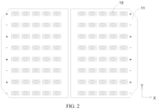
FIG. 2 is a schematic structural diagram of solar cells and connecting members according to some embodiments of the present disclosure; -
FIG. 3 is a schematic structural diagram of solar cell strings according to some embodiments of the present disclosure; -
FIG. 4 is a schematic structural diagram of a machining device according to some embodiments of the present disclosure; -
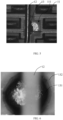
FIG. 5 is a microstructural diagram of a connecting member according to some embodiments of the present disclosure; -
FIG. 6 is a partial enlarged view of the connecting member according to some embodiments of the present disclosure; -
FIG. 7 is a schematic structural diagram of the connecting member according to some embodiments of the present disclosure; -
FIG. 8 is a microstructural diagram of a connecting member according to some other embodiments of the present disclosure; -
FIG. 9 is a partial enlarged view of the connecting member according to some other embodiments of the present disclosure; -
FIG. 10 is a schematic structural diagram of a connecting member according to some other embodiments of the present disclosure; and -
FIG. 11 is a schematic structural diagram of a connecting member according to some other embodiments of the present disclosure. -
- 1: solar cell string;
- 11: solar cell;
111: soldering region; - 12: electrode line;
- 13: connecting member;
- 131: first region;
- 132: second region;
- 133: recessed portion;
- 134: third region;
- 11: solar cell;
- 2: operating platform;
- 3: pressing tool;
- 31: bracket;
- 32: abutting member;
- 33: elastic member.
- The accompanying drawings herein are incorporated in and constitute a part of this specification, illustrate embodiments consistent with the present disclosure and, together with the specification, serve to explain the principles of the present disclosure.
- In order to better understand the technical solution of the present disclosure, embodiments of the present disclosure are described in detail below with reference to the accompanying drawings.
- It is to be made clear that the described embodiments are only some rather than all of the embodiments of the present disclosure. All other embodiments obtained by those of ordinary skill in the art based on the embodiments in the present disclosure without creative efforts fall within the protection scope of the present disclosure.
- The terms used in the embodiments of the present disclosure are intended only to describe particular embodiments and are not intended to limit the present disclosure. As used in the embodiments of the present disclosure and the appended claims, the singular forms of "a/an", "the", and "said" are intended to include plural forms, unless otherwise clearly specified by the context.
- It is to be understood that the term "and/or" used herein is merely an association relationship describing associated objects, indicating that three relationships may exist. For example, A and/or B indicates that there are three cases of A alone, A and B together, and B alone. In addition, the character "/" herein generally means an "or" relationship between the associated objects.
- It is to be noted that the location terms such as "above", "below", "left", and "right" described in the embodiments of the present disclosure are described with reference to the angles shown in the accompanying drawings, and should not be construed as limitations on the embodiments of the present disclosure. In addition, in the context, it is to be further understood that, when one element is referred to as being connected "above" or "below" another element, the one element may be directly connected "above" or "below" another element, or connected "above" or "below" another element via an intermediate element.
- As shown in
FIG. 1 to FIG. 7 , some embodiments of the present disclosure provide a photovoltaic module, includingsolar cell strings 1 and electrode lines 12. Thesolar cell strings 1 each includesolar cells 11 arranged in parallel. The electrode lines 12 are located on one sides of thesolar cells 11 and configured to connect adjacentsolar cells 11.soldering regions 111 are arranged on one sides of thesolar cells 11 facing the electrode lines 12. Thesoldering regions 111 are arranged apart along a length direction X of the photovoltaic module. Connectingmembers 13 are arranged in thesoldering regions 111, such that theelectrode lines 12 are connected to thesoldering regions 111 of thesolar cells 11 through the connectingmembers 13. The connectingmembers 13 each include afirst region 131 and asecond region 132. Thesecond region 132 is arranged around thefirst region 131, and transparency of thesecond region 132 is greater than that of thefirst region 131. - The
solar cell 11 provided in some embodiments of the present disclosure is a rear-backsolar cell 11. A positive busbar and a negative busbar in thesolar cell 11 are both located on a same side of thesolar cell 11. Thesoldering region 111 is arranged on the positive busbar and the negative busbar of thesolar cell 11. Theelectrode line 12 is configured to connect the positive busbars and the negative busbars between adjacentsolar cells 11. Therefore, along a thickness direction Z of the photovoltaic module, theelectrode lines 12 can be located on a same side of the adjacentsolar cells 11. - The positive busbar and the negative busbar of the rear-back
solar cell 11 are both designed on a rear surface of the solar cell, and at the same time, a solder joint between a busbar and theelectrode line 12 at an edge almost fit an edge of thesolar cell 11. Therefore, there is a greater risk of problems such as cold soldering during the soldering. The arrangement of the connectingmember 13 in thesoldering region 111 can reduce a possibility of cold soldering between theelectrode line 12 and thesolar cell 11, helping to increase a yield of the photovoltaic module. Main components of the connectingmember 13 are different metals such as tin-lead or tin-bismuth-silver, and organic solvents such as flux are also added to the connectingmember 13 to facilitate soldering of theelectrode line 12 and thesolar cell 11. During the soldering, the connectingmember 13 is heated and melted, and the organic solvents in the connectingmember 13 may precipitate along a direction from thefirst region 131 to thesecond region 132. After the soldering, the precipitated organic solvents may gather at edges of thefirst region 131 in the connectingmember 13 to form thesecond region 132. Due to greater transparency of the organic solvents, the transparency of thesecond region 132 is approximately 70% to 80% greater than the transparency of thefirst region 131. - In some possible embodiments, after the
electrode line 12 is connected to thesoldering region 111, the connectingmember 13 has a recessedportion 133 on a surface. - Main components of the connecting
member 13 are different metals such as tin-lead or tin-bismuth-silver, and organic solvents are also added to the connectingmember 13 to facilitate soldering of theelectrode line 12 and thesolar cell 11. When the connectingmember 13 is heated, the organic solvents may volatilize by heat, and a recessedportion 133 may be formed on the surface of the connectingmember 13. After the organic solvents volatilize, it is beneficial to improve strength of the soldering between theelectrode line 12 and thesolar cell 11. - As shown in
FIG. 3 ,FIG. 9 , andFIG. 10 , in some possible embodiments, along the thickness direction Z of the photovoltaic module, theelectrode line 12 overlaps with the connectingmember 13, and in projections along the thickness direction Z of the photovoltaic module, the projection of the recessedportion 133 on thesolar cell 11 is located outside a projection region of theelectrode line 12 on thesolar cell 11. - In some possible embodiments, in the projections along the thickness direction Z of the photovoltaic module, the projection of the recessed
portion 133 on thesolar cell 11 overlaps with the projection of theelectrode line 12 on thesolar cell 11, such that the recessedportion 133 also exists at a position where theelectrode line 12 overlaps with the connectingmember 13. - When the connecting
member 13 is heated, the organic solvents in the connectingmember 13 volatilize when the connectingmember 13 is not completely cured, such that the connectingmember 13 has the recessedportion 133 on the surface after curing. Before the connectingmember 13 is heated, the organic solvents are evenly mixed with other components in the connectingmember 13. Therefore, the recessedportion 133 formed due to the volatilization of the organic solvents may overlap with theelectrode line 12 or may not overlap with theelectrode line 12. When the recessedportion 133 overlaps with theelectrode line 12, an area of contact between theelectrode line 12 and the connectingmember 13 may be reduced, so strength of the connection between theelectrode line 12 and the connectingmember 13 may be reduced. Therefore, in an ideal state, the projection of the recessedportion 133 is located outside the projection of theelectrode line 12. - As shown in
FIG. 9 andFIG. 10 , in some possible embodiments, the connectingmember 13 has recessedportions 133 on the surface, and the recessedportions 133 are arranged apart. - During the volatilization of the organic solvents, gaseous organic solvents may form bubbles on the surface of the connecting
member 13. As the gaseous organic solvents in the bubbles gradually increase, the bubbles break to form recessedportions 133 on the surface of the connectingmember 13. During the gasification of the organic solvents, adjacent organic solvents may gather into a bubble and then volatilize from the connectingmember 13, such that the recessedportions 133 on the surface of the connectingmember 13 are arranged apart. - In some possible embodiments, the connecting
member 13 has recessedportions 133 on the surface, and adjacent recessedportions 133 are interconnected with each other. - In the case of more organic solvents in the connecting
member 13 or a higher heating temperature, reaction is violent when the organic solvents volatilize, such that bubbles may be formed multiple times at a same position or similar positions on the surface of the connectingmember 13. After breakage of the bubbles, recessedportions 133 interconnected with each other may be formed. - As shown in
FIG. 10 , in some possible embodiments, the connectingmember 13 includes afirst region 131 and asecond region 132, wherein thesecond region 132 is arranged around thefirst region 131. Both thefirst region 131 and thesecond region 132 are provided with the recessedportions 133, and an average size of the recessedportions 133 in thefirst region 131 is smaller than an average size of the recessedportions 133 in thesecond region 132. - When the connecting
member 13 is heated, the organic solvents in the connectingmember 13 have one part that may volatilize in thefirst region 131 and the other part that may flow from thefirst region 131 to thesecond region 132 and then volatilize in thesecond region 132, such that the organic solvents volatilizing in thefirst region 131 are smaller than the organic solvents volatilizing in thesecond region 132. Therefore, sizes of the recessedportions 133 in thefirst region 131 are smaller than sizes of the recessedportions 133 in thesecond region 132, and it is also possible that a number of the recessedportions 133 in thefirst region 131 is less than that of the recessedportions 133 in thesecond region 132. - In some possible embodiments, arrangement density of the recessed
portions 133 in thesecond region 132 ranges from 3×10³ pcs/mm2 to 13×104 pcs/mm2. - The arrangement density of the recessed
portions 133 in thesecond region 132 may be 3×10³ pcs/mm2, 13×103 pcs/mm2, 23×103 pcs/mm2, 33×103 pcs/mm2, 43×103 pcs/mm2, 53×103 pcs/mm2, 63×103 pcs/mm2, 73×103 pcs/mm2, 83×103 pcs/mm2, 93×103 pcs/mm2, 3×10⁴ pcs/mm2, 13×104 pcs/mm2 , or the like. If the number of the recessedportions 133 in thesecond region 132 is less than 3×10³ pcs/mm2, an effect of volatilization of the organic solvents may be reduced, resulting in residues of the organic solvents in thesecond region 132, thereby reducing reliability of the soldering between theelectrode line 12 and thesolar cell 11. If the number of the recessedportions 133 in thesecond region 132 is greater than 3×10⁴ pcs/mm2, an area of contact between the connectingmember 13 in thesecond region 132 and theelectrode line 12 may be reduced, and strength of the connection between thesecond region 132 and theelectrode line 12 may be reduced. - As shown in
FIG. 11 , in some possible embodiments, the connectingmember 13 further includes athird region 134, and thethird region 134 is arranged around thesecond region 132. During the heating of the connectingmember 13, the organic solvents may precipitate along a direction from thefirst region 131 to thesecond region 132. During the precipitation, part of the organic solvents may volatilize in thefirst region 131 and thesecond region 132, such that recessedportions 133 are formed in thefirst region 131 and thesecond region 132, and some non-volatilizing organic solvents may continue to precipitate to edges of thesecond region 132, forming athird region 134 around thesecond region 132. - Along a width direction Y of the photovoltaic module, a width of the
third region 134 is less than that of thesecond region 132. During the heating of the connectingmember 13, most of the organic solvents may volatilize in thefirst region 131 or thesecond region 132, and a small part of the organic solvents may form thethird region 134. Therefore, the width of thethird region 134 is less than that of thesecond region 132. - The
third region 134 is composed of non-volatilizing organic solvents. Therefore, thethird region 134 includes no recessedportions 133 formed due to the volatilization of the organic solvents, arrangement density of the recessedportions 133 in thefirst region 131 may range from 100 pcs/mm2 to 2000 pcs/mm2. For example, the arrangement density of the recessedportions 133 in thefirst region 131 may be 100 pcs/mm2, 500 pcs/mm2, 1000 pcs/mm2, 1500 pcs/mm2, 2000 pcs/mm2, or the like. Compared with thefirst region 131 and thesecond region 132, arrangement density of the recessedportions 133 in thethird region 134 may range from 0 to 100 pcs/mm2. For example, the arrangement density of the recessedportions 133 in thethird region 134 may be 0, 20 pcs/mm2, 40 pcs/mm2, 60 pcs/mm2, 80 pcs/mm2, 100 pcs/mm2, or the like. Therefore, thethird region 134 has higher flatness than thefirst region 131 and thesecond region 132. In thefirst region 131 and thesecond region 132 of the connectingmember 13, the organic solvents precipitate, main components are tin-lead, tin-bismuth-silver, or the like, and transparency thereof is less than that of the organic solvents. Transparency of thethird region 134 is approximately 70% to 80%, which may be, for example, 70%, 75%, 80%, or the like. Thefirst region 131 and thesecond region 132 are opaque or less transparent than thethird region 134. - As shown in
FIG. 5 to FIG. 7 , in some possible embodiments, thefirst region 131 has recessedportions 133 on the surface. In the projections along the thickness direction of the photovoltaic module, the projection of the recessedportion 133 on thesolar cell 11 is located outside a range of the projection of theelectrode line 12 on thesolar cell 11. - The
electrode line 12 is connected to thesolar cell 11 through the connectingmember 13. Therefore, theelectrode line 12 has an overlapping portion with thefirst region 131. If the recessedportion 133 is arranged in the overlapping portion between theelectrode line 12 and thefirst region 131, the area of contact between theelectrode line 12 and the connectingmember 13 may be reduced, resulting in a decrease in the strength of the connection between theelectrode line 12 and the connectingmember 13. If the recessedportion 133 in thefirst region 131 is outside an overlapping region between theelectrode line 12 and thefirst region 131, an influence of the recessedportion 133 on the strength of the connection between theelectrode line 12 and the connectingmember 13 can be reduced. - In some possible embodiments, along the width direction Y of the photovoltaic module, the width of the
second region 132 is less than or equal to 30 µm. - In the connecting
member 13, one part of the organic solvents volatilize during the soldering, and the other part of the organic solvents precipitate to form thesecond region 132. If the width of thesecond region 132 is greater than 30 µm, content of the organic solvents in the connectingmember 13 is more, resulting in precipitation of more organic solvents, and there may be residues of the organic solvents in thefirst region 131, affecting strength of the soldering between theelectrode line 12 and thesolar cell 11. - In some possible embodiments, the recessed
portion 133 is formed by the breakage of the bubbles formed by the gasification of the organic solvents in the connectingmember 13. Therefore, in the projections along the thickness direction Z of the photovoltaic module, the projection of the recessedportion 133 in thesolar cell 11 is in a shape of a circle or an ellipse. - Since the projection of the recessed
portion 133 along the thickness direction Z of the photovoltaic module is in the shape of a circle or an ellipse, the recessedportion 133 may be hemispherical or cylindrical, which facilitates the organic solvents to volatilize from the connectingmember 13, reducing the residues of the organic solvents in the connectingmember 13, and helping to improve the reliability of the soldering between theelectrode line 12 and thesolar cell 11. - In some possible embodiments, along the width direction of the photovoltaic module, the size of the recessed
portion 133 ranges from 3 µm to 15 µm. - The size of the recessed
portion 133 may be 3 µm, 6 µm, 9 µm, 12 µm, 15 µm, or the like, which is 9 µm in some embodiments. If a width of the recessedportion 133 is less than 3 µm, an effect of volatilization of the organic solvents in the connectingmember 13 may be reduced. If the width of the recessedportion 133 increases, it is easier for the organic solvents to volatilize. Along the width direction Y of the photovoltaic module, a width of the connectingmember 13 ranges from 0.2 mm to 1 mm. If the width of the recessedportion 133 is greater than 15 µm, the recessedportion 133 accounts for a larger portion in the connectingmember 13, which may affect the strength of the connection between theelectrode line 12 and the connectingmember 13. - As shown in
FIG. 5 to FIG. 7 , in some possible embodiments, the organic solvents in the connectingmember 13 have one part volatilizing in thefirst region 131 to form the recessedportions 133 and the other part precipitating from thefirst region 131 to form thesecond region 132. The arrangement density of the recessedportions 133 in thefirst region 131 may range from 100 pcs/mm2 to 2000 pcs/mm2. For example, the arrangement density of the recessedportions 133 in thefirst region 131 may be 100 pcs/mm2, 500 pcs/mm2, 1000 pcs/mm2, 1500 pcs/mm2, 2000 pcs/mm2, or the like. The arrangement density of the recessedportions 133 in thesecond region 132 may be 0, 20 pcs/mm2, 40 pcs/mm2, 60 pcs/mm2, 80 pcs/mm2, 100 pcs/mm2, or the like. The arrangement density of the recessedportions 133 in thesecond region 132 is lower. Therefore, thesecond region 134 has lower pore density and higher flatness. - In some possible embodiments, the
first region 131 may be solder paste. The solder paste may improve capillarity and wettability, and reduce a possibility of cold soldering between theelectrode line 12 and thesolar cell 11. At the same time, the solder paste may also isolate the air to prevent oxidation of solder joints between theelectrode line 12 and thesolar cell 11, helping to improve the reliability of the soldering between theelectrode line 12 and thesolar cell 11. - The
solar cells 11 arranged in parallel are connected into thesolar cell string 1 through theelectrode line 12, an upper surface and a lower surface of thesolar cell string 1 are both provided with adhesive films, the upper surface of thesolar cell string 1 is further provided with photovoltaic glass connected to thesolar cell string 1 through the adhesive film, and the lower surface of thesolar cell string 1 is further provided with photovoltaic glass or a back sheet which is also connected to thesolar cell string 1 through the adhesive film to form the photovoltaic module. - Some embodiments of the present disclosure further provide a manufacturing method for manufacturing a photovoltaic module for a photovoltaic module. The photovoltaic module includes
solar cell strings 1, a back sheet, an adhesive film, and photovoltaic glass. Thesolar cell string 1 includessolar cells 11, aelectrode line 12, and connectingmembers 13. Theelectrode line 12 is connected to thesolar cells 11 through the connectingmembers 13. - The method for manufacturing a photovoltaic module includes:
- S1: placing the connecting
members 13 insoldering regions 111 of thesolar cells 11; - S2: placing the
solar cells 11 with the connectingmembers 13 on anoperating platform 2; - S3: placing the
electrode line 12 on one sides of thesolar cells 11 provided with the connectingmembers 13; - S4: heating the
electrode line 12 and the connectingmembers 13 to obtain thesolar cell string 1; and - S5: laminating the back sheet, the adhesive film, the
solar cell strings 1, and the photovoltaic glass to obtain the photovoltaic module. - The connecting
member 13 is arranged between theelectrode line 12 and thesolar cell 11, which can improve the strength of the connection between theelectrode line 12 and thesolar cell 11 and reduce a possibility of cold soldering. Both the connectingmember 13 and theelectrode line 12 are placed on a surface of thesolar cell 11, which omits the step of curing the connectingmember 13 on thesolar cell 11, helping to improve manufacturing efficiency of thesolar cell string 1. - When the connecting
members 13 are placed in thesoldering regions 111 of thesolar cells 11, the method for manufacturing a photovoltaic module includes: S11: printing the connectingmembers 13 in thesoldering regions 111 of thesolar cells 11. - The connecting
member 13 is arranged in thesoldering region 111 by printing, which facilitates the control over a position and a shape of the connectingmember 13, enabling the connectingmember 13 to be located at a position where theelectrode line 12 and thesolar cell 11 are soldered. When theelectrode line 12 is soldered to thesolar cell 11, the connectingmember 13 can reduce a possibility of colder soldering. - As shown in
FIG. 2 andFIG. 3 , in some possible embodiments, thesolar cell 11 includes a positive busbar and a negative busbar, the positive busbars and the negative busbars are alternately arranged on thesolar cells 11 along a width direction Y of the photovoltaic module, and positions of the positive busbars and the negative busbars in thesolar cells 11 are consistent. Therefore, when thesolar cells 11 are placed on theoperating platform 2, along a length direction X of the photovoltaic module, in adjacentsolar cells 11, the positive busbars are located on a same straight line and the negative busbars are located on a same straight line. - When the
solar cells 11 with the connectingmembers 13 are placed on theoperating platform 2, the method for manufacturing a photovoltaic module includes: S21: rotating one of two adjacentsolar cells 11 by 180° such that, in the adjacentsolar cells 11, the positive busbar of one and the negative busbar of the other are located on a same straight line along the length direction X of the photovoltaic module. - The
electrode line 12 is configured to connect the positive busbars and the negative busbars in the adjacentsolar cells 11, and in the adjacentsolar cells 11, the positive busbar of one and the negative busbar of the other are located on a same straight line, such that theelectrode line 12 can be arranged on one side of thesolar cell 11 provided with the positive busbar and the negative busbar. - After the
electrode lines 12 are placed on one sides of thesolar cells 11 provided with the connectingmembers 13, the method for manufacturing a photovoltaic module includes: S31: fixing theelectrode lines 12 to the sides of thesolar cells 11 provided with the connectingmembers 13. - A force is applied to the
electrode line 12 on a side of theelectrode line 12 away from thesolar cell 11 to fix theelectrode line 12 to thesolar cell 11, which reduces a possibility of displacement of theelectrode line 12 during subsequent soldering between theelectrode line 12 and thesolar cell 11, helping to increase a yield of thesolar cell string 1. - In some possible embodiments, the
operating platform 2 for placing thesolar cell 11 can heat thesolar cell 11 and then solder thesolar cell 11 and theelectrode line 12. - When the
solar cells 11 are heated to obtain thesolar cell string 1, the method for manufacturing a photovoltaic module includes: a heating temperature ranging from 130°C to 220°C, and heating time ranging from 1.5 s to 6 s. - During the heating, the
solar cell 11 transfers heat emitted by a heating platform to the connectingmember 13 and theelectrode line 12, causing the connectingmember 13 to melt to connect theelectrode line 12 and thesolar cell 11. During the heating, the heating temperature may be 130°C, 150°C, 170°C, 190°C, 210°C, 220°C, or the like, and the heating time may be 1.5 s, 2.5 s, 3.5 s, 4.5 s, 5.5 s, 6 s, or the like. The organic solvents in the connectingmember 13 have one part volatilizing in thefirst region 131 to form recessedportions 133 and the other part precipitating from thefirst region 131 to form thesecond region 132. - In some possible embodiments, a heating apparatus is arranged on one side of the
solar cell 11 away from theoperating platform 2. The heating apparatus may be an infrared lamp box. Theelectrode line 12 and the connectingmember 13 are heated by the heating apparatus, thereby soldering thesolar cell 11 and theelectrode line 12. - When the
solar cells 11 are heated to obtain thesolar cell string 1, the method for manufacturing a photovoltaic module includes: a heating temperature ranging from 230°C to 240°C, and heating time being less than or equal to 5 s. - When the
solar cell 11 is heated, the heating temperature may be 230°C, 235°C, 240°C, or the like. In the manner of heating the connectingmember 13 and theelectrode line 12 through the infrared heating apparatus, thesolar cell 11 is not required to transfer heat, and at the same time, the infrared heating apparatus can provide a higher temperature. Therefore, the soldering between theelectrode line 12 and thesolar cell 11 can be completed when the heating time is less than or equal to 5 s. - In some possible embodiments, when the connecting
members 13 are placed in thesoldering regions 111 of thesolar cells 11, the method for manufacturing a photovoltaic module includes: fixing the connectingmembers 13 to thesolar cells 11 by heating. - The connecting
member 13 is first fixed to thesolar cell 11 by heating, which limits a relative position between the connectingmember 13 and thesolar cell 11. In the step of soldering theelectrode line 12 and thesolar cell 11 through the connectingmember 13, a possibility of displacement of the connectingmember 13 is reduced, and a possibility of colder soldering between theelectrode line 12 and thesolar cell 11 is reduced. - The connecting
member 13 may be solder paste. When the connectingmembers 13 are fixed to thesolar cells 11 by heating, the method for manufacturing a photovoltaic module includes: S21: heating the solder paste to 120°C to 180°C for 10 s to 60 s. - The
solar cell 11 printed with the solder paste is placed in a curing furnace for heating. A heating temperature may be 120°C, 130°C, 140°C, 150°C, 160°C, 170°C, 180°C, or the like, and heating time may be 10 s, 20 s, 30 s, 40 s, 50 s, 60 s, or the like. The solder paste is cured and fixed to thesolar cell 11. The solder paste includes organic solvents such as flux. During the curing of the solder paste, the organic solvents such as flux in the solder paste may volatilize or precipitate from a center of the solder paste to edges, which reduces content of the organic solvents in the solder paste and can improve strength of the soldering between theelectrode line 12 and thesolar cell 11. - Some embodiments of the present disclosure further provide a machining device, for manufacturing a photovoltaic module. The machining device includes an
operating platform 2, pressing tools 3, and a heating apparatus. The pressing tool 3 is mounted on theoperating platform 2 and configured to limit positions ofsolar cells 11 andelectrode lines 12 in the photovoltaic module. The heating apparatus is configured to heat connectingmembers 13 and the electrode lines 12. - The
solar cell 11 is placed on theoperating platform 2. One side of thesolar cell 11 provided with no positive busbar and no negative busbar faces theoperating platform 2. The pressing tool 3 includes abracket 31 and abuttingmembers 32. Thebracket 31 is configured to fix positions of the abuttingmembers 32, such that the abuttingmembers 32 are located above theelectrode line 12. The abuttingmembers 32 are connected to thebracket 31 through anelastic member 33. When the pressing tool 3 fixes the position of theelectrode line 12, one ends of the abuttingmembers 32 away from thebracket 31 abut against theelectrode line 12 and may compress theelastic member 33 at the same time. An elastic force of theelastic member 33 may be transferred to theelectrode line 12 through the abuttingmembers 32, such that theelectrode line 12 is fixed to thesolar cells 11, facilitating heating of thesolar cells 11, the connectingmembers 13, and theelectrode line 12 to form thesolar cell string 1. - In some possible embodiments, the heating apparatus is located in the
operating platform 2, thesolar cell 11 can be placed on a surface of the heating apparatus, and thesolar cell 11 is heated through the heating apparatus to melt the connectingmember 13 and then connect theelectrode line 12 and thesolar cell 11. - Through the arrangement of the heating apparatus in the
operating platform 2, one side of thesolar cell 11 provided with the busbars can be heated, heat is transferred, through thesolar cell 11, to the side of thesolar cell 11 provided with the busbars to heat the connectingmember 13 and theelectrode line 12, and then theelectrode line 12 and thesolar cell 11 can be connected. - In some possible embodiments, the heating apparatus is a curing furnace, a heating member is arranged in the curing furnace, the
solar cell 11 can enter the curing furnace along with theoperating platform 2, the heating member is located on one side of thesolar cell 11 where the connectingmember 13 and theelectrode line 12 are placed, and thesolar cell 11, the connectingmember 13, and theelectrode line 12 are heated through the heating member, to connect theelectrode line 12 and thesolar cell 11. - The heating member may be an infrared heating apparatus, and the connecting
member 13 and theelectrode line 12 can be directly heated through the infrared heating apparatus. At the same time, a heating temperature of the infrared heating apparatus is higher, such that the connectingmember 13 can melt more easily and then connect theelectrode line 12 and thesolar cell 11. - As shown in
FIG. 4 , in some possible embodiments, the pressing tool 3 includes abracket 31 and abuttingmembers 32. Thebracket 31 is configured to fix positions of the abuttingmembers 32. The abuttingmembers 32 are configured to provide forces for theelectrode line 12. The abuttingmembers 32 are connected to thebracket 31 through anelastic member 33. When the pressing tool 3 fixes the position of theelectrode line 12, one ends of the abuttingmembers 32 away from thebracket 31 abut against theelectrode lines 12 and may compress theelastic member 33 at the same time. An elastic force of theelastic member 33 may be transferred to theelectrode line 12 through the abuttingmembers 32, such that theelectrode line 12 is fixed to thesolar cells 11. - Through the
operating platform 2 and the pressing tool 3, relative positions of thesolar cell 11 and theelectrode line 12 can be limited, which reduces a possibility of displacement of theelectrode line 12 during the soldering and helps to increase a yield of the photovoltaic module. - In some possible embodiments, the machining device further includes a heating apparatus and a soldering apparatus. The heating apparatus and the soldering apparatus are located upstream of the operating platform and downstream of the operating platform respectively. After the connecting members are arranged on the surface of the solar cells, the heating apparatus is entered first, the connecting members are cured, and the connecting members are fixed to the solar cells. Then, the solar cells are placed on the operating platform, and relative positions of the electrode lines and the solar cells are limited through the pressing tools, which are finally placed in the soldering apparatus to solder the electrode lines and the solar cells.
- Some embodiments of the present disclosure provide a photovoltaic module, a manufacturing method for manufacturing a photovoltaic module for a photovoltaic module, and a machining device. The photovoltaic module includes
solar cell strings 1 and electrode lines 12. Thesolar cell string 1 includessolar cells 11 arranged in parallel, and theelectrode line 12 is located on one sides of thesolar cells 11 and configured to connect adjacentsolar cells 11 to form thesolar cell string 1.soldering regions 111 are arranged apart on thesolar cell 11 along a length direction X of the photovoltaic module, connectingmembers 13 are arranged in thesoldering regions 111, theelectrode line 12 is located on one sides of thesolar cells 11 provided with the connectingmembers 13, and the connectingmembers 13 can reduce a possibility of cold soldering between theelectrode line 12 and thesolar cells 11, helping to increase a yield of thesolar cell string 1. The connectingmember 13 includes afirst region 131 and asecond region 132. Thesecond region 132 is arranged around thefirst region 131, and transparency of thesecond region 132 is greater than that of thefirst region 131. - The above are merely some embodiments of the present disclosure, and are not intended to limit the present disclosure. For those skilled in the art, the present disclosure may be subject to various modifications and changes. Any modification, equivalent replacement, improvement and the like within the spirit and principle of the present disclosure all fall within the protection scope of the present disclosure.
Claims (15)
- A photovoltaic module, comprising:a solar cell string (1) comprising solar cells (11) which are arranged in parallel along a length direction of the photovoltaic module; andelectrode lines (12), each of the electrode lines (12) being located on a side of a corresponding solar cell (11) and configured to connect adjacent solar cells (11),wherein soldering regions (111) are arranged on a side of each of the solar cells (11) facing the electrode lines (12), and arranged apart along the length direction of the photovoltaic module, the electrode lines (12) are connected to the soldering regions (111), connecting members (13) are arranged between the soldering regions (111) and the electrode lines (12), the electrode lines (12) are connected to the soldering regions (111) through the connecting members (13), and each of the connecting members (13) comprises a first region (131) and a second region (132),wherein the second region (132) is arranged around the first region (131), and transparency of the second region (132) is greater than transparency of the first region (131).
- The photovoltaic module according to claim 1, wherein the second region (132) has a width less than or equal to 30 µm; or
wherein the second region (132) has a surface pore density less than a surface pore density of the first region (131). - The photovoltaic module according to claim 1, wherein at least one recessed portion (133) is arranged on a surface of the first region (131).
- The photovoltaic module according to claim 4, wherein, in the first region (131), an arrangement density of the at least one recessed portion (133) ranges from 100 pcs/mm2 to 2000 pcs/mm2; or
wherein, along a thickness direction of the photovoltaic module, a projection of the at least one recessed portion (133) is located outside projections of the electrode lines (12). - The photovoltaic module according to claim 3, wherein the at least one recessed portion comprises a plurality of recessed portions (133) arranged on the surface of the first region (131), and the plurality of recessed portions (133) are arranged apart from each other on the surface of the first region (131).
- The photovoltaic module according to claim 3, wherein the at least one recessed portion comprises a plurality of recessed portions (133) arranged on the surface of the first region (131), and adjacent recessed portions (133) of the plurality of recessed portions (133) are interconnected with each other.
- The photovoltaic module according to claim 3, wherein, along a thickness direction of the photovoltaic module, a projection of each of the at least one recessed portion (133) in a corresponding solar cell (11) is in a shape of a circle or an ellipse.
- The photovoltaic module according to claim 3, wherein, along a thickness direction of the photovoltaic module, a projection of each of the at least one recessed portion (133) in the solar cell (11) has a size ranging from 3 µm to 15 µm along a width direction of the photovoltaic module.
- The photovoltaic module according to claim 1, wherein the first region (131) is provided with a solder paste.
- A method for manufacturing a photovoltaic module, wherein
the photovoltaic module comprises a solar cell string (1), a back sheet, an adhesive film, and photovoltaic glass, and the solar cell string (1) comprises solar cells (11), electrode lines (12), and connecting members (13), wherein the method comprises:placing the connecting members (13) in soldering regions (111) of the solar cells (11);placing the solar cells (11) with the connecting members (13) on an operating platform (2);placing each of the electrode lines (12) on a side of a corresponding solar cell (11) provided with the connecting members (13) thereon;heating the electrode lines (12) and the connecting members (13) to obtain the solar cell string (1); andlaminating the back sheet, the adhesive film, the solar cell strings (1), and the photovoltaic glass to obtain the photovoltaic module. - The method according to claim 10, wherein each of the solar cells (11) comprises a positive busbar and a negative busbar, the positive busbars and the negative busbars are alternately arranged along a width direction of the photovoltaic module, and when the solar cells (11) with the connecting members (13) are placed on the operating platform (2), the method comprises:rotating one of two adjacent solar cells (11) by 180° such that, in the adjacent solar cells (11), the positive busbar of one of the two adjacent solar cells and the negative busbar of the other of the two adjacent solar cells are located on a same straight line along a length direction of the photovoltaic module; orwherein the heating the electrode lines (12) and the connecting members (13) to obtain the solar cell string (1) is performed at a heating temperature ranging from 130°C to 220°C for 1.5 s to 6 s; orwherein, the heating the electrode lines (12) and the connecting members (13) to obtain the solar cell string (1) is performed at a heating temperature ranging from 230°C to 240°C for no more than 5 s.
- A machining device, for manufacturing a photovoltaic module comprising solar cells (11), electrode lines (12), and connecting members (13), wherein the machining device comprises:an operating platform (2), wherein the solar cells (11) are located on a surface of the operating platform (2);a pressing tool (3), located on a side of the operating platform (2) where the solar cells (11) are placed; anda heating apparatus, configured to heat the solar cells (11) and the connecting members (13).
- The machining device according to claim 12, wherein the heating apparatus is located in the operating platform (2), and the solar cells (11) are placed in the heating apparatus; orherein the heating apparatus is a curing furnace, and the operating platform (2) is capable of entering the curing furnace;the curing furnace comprises a heating member, and the heating member is located on a side of a corresponding solar cell (11) away from the operating platform (2).
- The machining device according to claim 12, wherein the pressing tool (3) comprises a bracket (31) and abutting members (32), and the bracket (31) is arranged parallel to each of the electrode lines (12) along a height direction of the machining device, and each of the abutting members (32) has one end connected to the bracket (31) and another end capable of abutting against one of the electrode lines (12).
- The machining device according to claim 14, wherein the pressing tool (3) further comprises elastic members (33), and the bracket (31) and the abutting members (32) are connected to each other through the elastic members (33).
Applications Claiming Priority (2)
| Application Number | Priority Date | Filing Date | Title |
|---|---|---|---|
| CN202310610355.1A CN116404061A (en) | 2023-05-26 | 2023-05-26 | Photovoltaic module, manufacturing method and processing equipment of photovoltaic module |
| CN202310609235.XA CN116487463B (en) | 2023-05-26 | 2023-05-26 | Photovoltaic module and manufacturing method thereof |
Publications (2)
| Publication Number | Publication Date |
|---|---|
| EP4468372A2 true EP4468372A2 (en) | 2024-11-27 |
| EP4468372A3 EP4468372A3 (en) | 2024-12-18 |
Family
ID=87519920
Family Applications (1)
| Application Number | Title | Priority Date | Filing Date |
|---|---|---|---|
| EP23188341.4A Pending EP4468372A3 (en) | 2023-05-26 | 2023-07-28 | Photovoltaic module, manufacturing method for photovoltaic module, and machining device |
Country Status (4)
| Country | Link |
|---|---|
| US (1) | US20240395957A1 (en) |
| EP (1) | EP4468372A3 (en) |
| JP (1) | JP7592130B1 (en) |
| AU (1) | AU2023219797B2 (en) |
Family Cites Families (13)
| Publication number | Priority date | Publication date | Assignee | Title |
|---|---|---|---|---|
| JP2002263880A (en) * | 2001-03-06 | 2002-09-17 | Hitachi Cable Ltd | Pb-free solder, and connection lead wires and electrical components using the same |
| JP5159725B2 (en) * | 2009-08-27 | 2013-03-13 | 三洋電機株式会社 | Solar cell string and solar cell module using the same |
| DE102010017180A1 (en) * | 2010-06-01 | 2011-12-01 | Solarworld Innovations Gmbh | Solar cell, solar module, and method for wiring a solar cell, and contact wire |
| JP5231515B2 (en) * | 2010-12-17 | 2013-07-10 | シャープ株式会社 | Manufacturing method of solar cell |
| US8859322B2 (en) * | 2012-03-19 | 2014-10-14 | Rec Solar Pte. Ltd. | Cell and module processing of semiconductor wafers for back-contacted solar photovoltaic module |
| CN102751361A (en) | 2012-07-25 | 2012-10-24 | 合肥海润光伏科技有限公司 | Back-contact solar battery string and production method thereof |
| CN103203557A (en) | 2013-01-29 | 2013-07-17 | 太仓海润太阳能有限公司 | Welding method for back contact solar cell module |
| KR20160076393A (en) * | 2014-12-22 | 2016-06-30 | 엘지전자 주식회사 | Solar cell module |
| KR102622743B1 (en) * | 2017-02-13 | 2024-01-10 | 상라오 신위안 웨동 테크놀러지 디벨롭먼트 컴퍼니, 리미티드 | solar cell and solar cell module |
| KR101941237B1 (en) * | 2017-09-13 | 2019-01-23 | 한국에너지기술연구원 | Solar cell array, Solar cell module and Method for manufacturing the same |
| CN111785804A (en) | 2020-05-27 | 2020-10-16 | 泰州隆基乐叶光伏科技有限公司 | A method and system for producing a back-contact battery assembly |
| CN115117206B (en) * | 2022-08-30 | 2022-12-16 | 苏州小牛自动化设备有限公司 | Manufacturing method of photovoltaic module, battery string and photovoltaic module |
| CN115732580A (en) * | 2022-12-12 | 2023-03-03 | 浙江晶科能源有限公司 | Photovoltaic modules |
-
2023
- 2023-07-27 JP JP2023122880A patent/JP7592130B1/en active Active
- 2023-07-28 EP EP23188341.4A patent/EP4468372A3/en active Pending
- 2023-07-31 US US18/362,944 patent/US20240395957A1/en active Pending
- 2023-08-21 AU AU2023219797A patent/AU2023219797B2/en active Active
Also Published As
| Publication number | Publication date |
|---|---|
| EP4468372A3 (en) | 2024-12-18 |
| AU2023219797B2 (en) | 2025-08-28 |
| AU2023219797A1 (en) | 2024-12-12 |
| JP2024170273A (en) | 2024-12-06 |
| US20240395957A1 (en) | 2024-11-28 |
| JP7592130B1 (en) | 2024-11-29 |
Similar Documents
| Publication | Publication Date | Title |
|---|---|---|
| CN107078174B (en) | Solar Cell Interconnects | |
| EP2216827A1 (en) | Solar battery module and method for manufacturing solar battery module | |
| WO2024108996A1 (en) | Segmented low-temperature welding ribbon, busbar-free ibc cell string, and cell assembly and packaging method therefor | |
| EP2528104A1 (en) | Back contact solar cell, wiring sheet, solar cell having wiring sheet, solar cell module and production method for solar cell having wiring sheet | |
| CN112201720B (en) | Preparation method of solar cell module and solar cell module | |
| KR20080100373A (en) | Method of combining photovoltaic cells and film for implementing them | |
| JP2011151334A (en) | Method of manufacturing solar cell module | |
| CN115224161B (en) | A new type of busbarless solar photovoltaic module manufacturing method | |
| CN116487463A (en) | Photovoltaic module, manufacturing method and processing equipment of photovoltaic module | |
| CN116404061A (en) | Photovoltaic module, manufacturing method and processing equipment of photovoltaic module | |
| CN114512573A (en) | A welding process for stress-free welding equipment for cells in the photovoltaic industry | |
| EP4468372A2 (en) | Photovoltaic module, manufacturing method for photovoltaic module, and machining device | |
| CN101937936B (en) | A solar cell module | |
| JP5100629B2 (en) | Manufacturing method of solar cell module | |
| CN110010707A (en) | Double-sided light receiving type solar cell module | |
| CN207852701U (en) | Wiring sheet | |
| JP5193605B2 (en) | Photovoltaic panel | |
| CN220628165U (en) | FPC acquisition device and battery module | |
| CN116190480A (en) | Photovoltaic unit, photovoltaic module and preparation method thereof | |
| EP3762974B1 (en) | Apparatus and method for manufacturing a solar cell arrangement | |
| CN222448900U (en) | Infrared heating equipment and welding device | |
| CN117637906A (en) | Cell string preparation method, photovoltaic module and preparation method thereof | |
| CN117637907A (en) | Cell string preparation method, photovoltaic module and preparation method thereof | |
| EP4598308A1 (en) | Solar cell string and solar cell module | |
| CN208596690U (en) | A kind of busbar and solar panel |
Legal Events
| Date | Code | Title | Description |
|---|---|---|---|
| PUAI | Public reference made under article 153(3) epc to a published international application that has entered the european phase |
Free format text: ORIGINAL CODE: 0009012 |
|
| STAA | Information on the status of an ep patent application or granted ep patent |
Free format text: STATUS: REQUEST FOR EXAMINATION WAS MADE |
|
| PUAL | Search report despatched |
Free format text: ORIGINAL CODE: 0009013 |
|
| 17P | Request for examination filed |
Effective date: 20230728 |
|
| AK | Designated contracting states |
Kind code of ref document: A2 Designated state(s): AL AT BE BG CH CY CZ DE DK EE ES FI FR GB GR HR HU IE IS IT LI LT LU LV MC ME MK MT NL NO PL PT RO RS SE SI SK SM TR |
|
| AK | Designated contracting states |
Kind code of ref document: A3 Designated state(s): AL AT BE BG CH CY CZ DE DK EE ES FI FR GB GR HR HU IE IS IT LI LT LU LV MC ME MK MT NL NO PL PT RO RS SE SI SK SM TR |
|
| RIC1 | Information provided on ipc code assigned before grant |
Ipc: H01L 31/05 20140101ALI20241113BHEP Ipc: H01L 31/048 20140101ALI20241113BHEP Ipc: H01L 31/0224 20060101AFI20241113BHEP |
|
| STAA | Information on the status of an ep patent application or granted ep patent |
Free format text: STATUS: EXAMINATION IS IN PROGRESS |
|
| 17Q | First examination report despatched |
Effective date: 20250801 |
|
| REG | Reference to a national code |
Ref country code: DE Ref legal event code: R079 Free format text: PREVIOUS MAIN CLASS: H01L0031022400 Ipc: H10F0077200000 |
|
| GRAP | Despatch of communication of intention to grant a patent |
Free format text: ORIGINAL CODE: EPIDOSNIGR1 |
|
| STAA | Information on the status of an ep patent application or granted ep patent |
Free format text: STATUS: GRANT OF PATENT IS INTENDED |
|
| RIC1 | Information provided on ipc code assigned before grant |
Ipc: H10F 77/20 20250101AFI20260224BHEP Ipc: H10F 19/80 20250101ALI20260224BHEP Ipc: H10F 19/90 20250101ALI20260224BHEP |
|
| INTG | Intention to grant announced |
Effective date: 20260311 |
|
| RIN1 | Information on inventor provided before grant (corrected) |
Inventor name: TAO, WUSONG Inventor name: WANG, LUCHUANG Inventor name: QIN, NIANNIAN |