EP4468249A2 - Datenverarbeitungsverfahren, vorrichtung, elektronische vorrichtung und speichermedium - Google Patents
Datenverarbeitungsverfahren, vorrichtung, elektronische vorrichtung und speichermedium Download PDFInfo
- Publication number
- EP4468249A2 EP4468249A2 EP23756730.0A EP23756730A EP4468249A2 EP 4468249 A2 EP4468249 A2 EP 4468249A2 EP 23756730 A EP23756730 A EP 23756730A EP 4468249 A2 EP4468249 A2 EP 4468249A2
- Authority
- EP
- European Patent Office
- Prior art keywords
- grid
- processed
- acquisition
- target
- sub
- Prior art date
- Legal status (The legal status is an assumption and is not a legal conclusion. Google has not performed a legal analysis and makes no representation as to the accuracy of the status listed.)
- Pending
Links
Images


Classifications
-
- G—PHYSICS
- G01—MEASURING; TESTING
- G01B—MEASURING LENGTH, THICKNESS OR SIMILAR LINEAR DIMENSIONS; MEASURING ANGLES; MEASURING AREAS; MEASURING IRREGULARITIES OF SURFACES OR CONTOURS
- G01B11/00—Measuring arrangements characterised by the use of optical techniques
- G01B11/24—Measuring arrangements characterised by the use of optical techniques for measuring contours or curvatures
-
- G—PHYSICS
- G06—COMPUTING OR CALCULATING; COUNTING
- G06T—IMAGE DATA PROCESSING OR GENERATION, IN GENERAL
- G06T17/00—Three-dimensional [3D] modelling for computer graphics
- G06T17/20—Finite element generation, e.g. wire-frame surface description, tesselation
-
- G—PHYSICS
- G06—COMPUTING OR CALCULATING; COUNTING
- G06T—IMAGE DATA PROCESSING OR GENERATION, IN GENERAL
- G06T15/00—Three-dimensional [3D] image rendering
- G06T15/10—Geometric effects
- G06T15/20—Perspective computation
-
- G—PHYSICS
- G06—COMPUTING OR CALCULATING; COUNTING
- G06T—IMAGE DATA PROCESSING OR GENERATION, IN GENERAL
- G06T17/00—Three-dimensional [3D] modelling for computer graphics
- G06T17/10—Constructive solid geometry [CSG] using solid primitives, e.g. cylinders, cubes
-
- G—PHYSICS
- G06—COMPUTING OR CALCULATING; COUNTING
- G06T—IMAGE DATA PROCESSING OR GENERATION, IN GENERAL
- G06T19/00—Manipulating three-dimensional [3D] models or images for computer graphics
- G06T19/20—Editing of three-dimensional [3D] images, e.g. changing shapes or colours, aligning objects or positioning parts
-
- G—PHYSICS
- G06—COMPUTING OR CALCULATING; COUNTING
- G06T—IMAGE DATA PROCESSING OR GENERATION, IN GENERAL
- G06T7/00—Image analysis
- G06T7/60—Analysis of geometric attributes
-
- G—PHYSICS
- G06—COMPUTING OR CALCULATING; COUNTING
- G06T—IMAGE DATA PROCESSING OR GENERATION, IN GENERAL
- G06T2200/00—Indexing scheme for image data processing or generation, in general
- G06T2200/24—Indexing scheme for image data processing or generation, in general involving graphical user interfaces [GUIs]
-
- G—PHYSICS
- G06—COMPUTING OR CALCULATING; COUNTING
- G06T—IMAGE DATA PROCESSING OR GENERATION, IN GENERAL
- G06T2207/00—Indexing scheme for image analysis or image enhancement
- G06T2207/20—Special algorithmic details
- G06T2207/20092—Interactive image processing based on input by user
-
- G—PHYSICS
- G06—COMPUTING OR CALCULATING; COUNTING
- G06T—IMAGE DATA PROCESSING OR GENERATION, IN GENERAL
- G06T2219/00—Indexing scheme for manipulating 3D models or images for computer graphics
- G06T2219/20—Indexing scheme for editing of 3D models
- G06T2219/2016—Rotation, translation, scaling
Definitions
- the present disclosure relates to the technical field of computer processing, e.g., to a data processing method and apparatus, an electronic device, and a storage medium.
- data may be acquired from an object at a plurality of angles so that a corresponding 3D model can be reconstructed from the acquired data.
- incomplete data may be acquired, resulting in an inaccurate reconstructed model.
- the present disclosure provides a data processing method and apparatus, an electronic device, and a storage medium to achieve the technical effects of improving data acquisition comprehensiveness and efficiency.
- the present disclosure provides a data processing method, comprising:
- the present disclosure provides data processing apparatus, comprising an acquisition unit starting module, a three-dimensional grid to be processed display module and a target display information adjustment module.
- the acquisition unit starting module is configured to start an acquisition unit upon receiving an instruction for determining a three-dimensional model corresponding to a target object.
- the three-dimensional grid to be processed display module is configured to, when a preset acquisition condition is met, generate a three-dimensional grid to be processed enclosing the target object and display it on a display interface of a device to which the acquisition unit belongs.
- the target display information adjustment module is configured to adjust target display information of a corresponding sub-grid in the three-dimensional grid to be processed based on a relative acquisition angle between the acquisition unit and the three-dimensional grid to be processed.
- the present disclosure provides an electronic device, comprising:
- the at least one program when executed by the at least one processor, causes the at least one processor to implement the above data processing method.
- the present disclosure provides a storage medium, with computer-executable instructions stored thereon, wherein the computer-executable instructions, when executed by a computer processor, cause the computer processor to implement the above data processing method.
- the present disclosure provides a computer program product, comprising a computer program carried on a non-transitory computer-readable storage medium, wherein the computer program comprises program codes for performing the above data processing method.
- the term “include” and variations thereof are open inclusion, that is, “including, but not limited to”.
- the term “based on” means “based at least in part on.”
- the term “one embodiment” means “at least one embodiment”.
- the term “another embodiment” means “at least one additional embodiment”;
- the term “some embodiments” means “at least some embodiments”. Relevant definitions for other terms will be given in the description below.
- the technical solutions of the present disclosure may be applied to any scenario where three-dimensional feature data of an object needs to be acquired. For example, when three-dimensional data needs to be acquired in a live streaming scenario or a graphic design scenario, the technical solutions may be adopted.
- FIG. 1 is a flowchart of a data processing method provided by Embodiment I of the present disclosure. This embodiment of the present disclosure is applicable to a scenario of acquiring three-dimensional data corresponding to a target object.
- the data processing method may be performed by a data processing apparatus that may be implemented in the form of software and/or hardware or implemented by an electronic device.
- the electronic device may be a mobile terminal, a personal computer (PC), a server, or the like.
- the data processing method of this embodiment includes the following steps.
- an acquisition apparatus is started upon receiving an instruction for determining a three-dimensional model corresponding to a target object.
- the apparatus for performing the data processing method provided by the embodiment of the present disclosure may be integrated into application software supporting a data processing function, and the software may be installed into an electronic device which may be a mobile terminal, a PC, or the like.
- the application software may be a type of software for acquiring object features.
- the application software will not be described redundantly here one by one as long as they can realize feature acquisition.
- Corresponding applications may be developed based on the technical solutions that may realize the functions mentioned in the technical solutions.
- the target object refers to any article of which a feature is to be acquired, such as a wearable article and a doll article.
- a current object on which acquisition needs to be performed is taken as the target object.
- the number of objects into shot may be one or more. If there is one object, the object may be taken as the target object. If there are a plurality of objects, the target object may be determined dynamically based on distance information of a camera to each object. For example, the object having a shortest distance may be taken as the target object. That is to say, a preset program may be deployed in advance within a terminal to determine the object closest to an image pickup apparatus as the target object based on the preset program. All the objects may be taken as the target objects.
- the target object may also be determined based on relative distance information between a plurality of objects into shot. For example, if the camera is close to an object, the object is the target object. There may be many objects within a circle of 1 cm in a neighborhood range of the object, and these objects located within the circle may be taken as the target objects. Alternatively, the object having the shortest distance to the camera is taken as the target object. The target object is inseparable from other objects, e.g., stacked, and therefore, the inseparable objects may be taken as the target object.
- the acquisition apparatus may be an image pickup apparatus having a shooting function. In practical use, the acquisition apparatus may be an image pickup apparatus to which an application software deployment terminal belongs, or an image pickup apparatus in communication with the deployment terminal. If deployed on a mobile terminal, the acquisition apparatus may be a built-in camera of the mobile terminal.
- the system receives the instruction for determining the three-dimensional model corresponding to the target object.
- the acquisition apparatus may be started to perform acquisition on the target object.
- a three-dimensional grid to be processed enclosing the target object is generated and displayed on a display interface of a device to which the acquisition apparatus belongs.
- the preset acquisition condition includes at least one of: the target object being present in a field of view of the acquisition apparatus; an acquisition control being triggered; and a display duration of the target object in the field of view reaching a preset duration threshold.
- the field of view refers to a region that the acquisition apparatus can shoot at a position, or a range that can be viewed.
- the acquisition control may be a key that can be displayed on the display interface of application software. The triggering of the key characterizes that acquisition needs to be performed on the target object and the three-dimensional grid enclosing the target object is generated. For example, if the user triggers the acquisition control, acquisition may be automatically triggered for the target object.
- the device to which the acquisition apparatus belongs may be a terminal device that the acquisition apparatus binds to, or may be a terminal device in remote communication with the acquisition apparatus.
- the three-dimensional grid to be processed may be a three-dimensional grid enclosing the target object, and is used to guide the user to acquire the data of the target object.
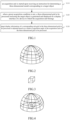
- the three-dimensional grid is a hemispherical transparent enclosure grid, as shown in FIG. 2 .
- the three-dimensional grid to be processed includes a plurality of sub-grids. For example, the sub-grids may be obtained by dividing as per longitudes and latitudes, or may be obtained by dividing as per a preset grid area.
- the benefit of determining the three-dimensional grid to be processed is that whether the data of the target object has been acquired may be determined based on display information of each sub-grid in the three-dimensional grid to be processed, thereby achieving the effect of acquisition progress visualization.
- the acquisition of data may be started by default when a duration of the acquisition apparatus facing the target object reaches a preset duration, and the corresponding three-dimensional grid is generated.
- the convenience of data acquisition is improved.
- the schematic diagram of the three-dimensional grid to be processed enclosing the target object ( FIG. 3 ) may be shown in FIG. 2
- the three-dimensional grid to be processed enclosing the target object may be displayed on the display interface of the device to which the acquisition apparatus belongs, and the schematic diagram of display may be shown in FIG. 4 .
- original display information of the three-dimensional grid to be processed may be set to semitransparent white.
- the original display information may also be an effect map allowing the target object to be seen. If the original display information is the effect map, an optical wave frequency band corresponding to the map cannot be acquired for the acquisition apparatus.
- the three-dimensional grid to be processed enclosing the target object may be generated on the display interface of the device to which the acquisition apparatus belongs.
- the benefits of enclosing the target object are as follows: the visual angle at which the image data of the target object is currently acquired may be determined; meanwhile, whether the complete data of the target object has been acquired may also be determined based on the three-dimensional grid to be processed.
- target display information of a corresponding sub-grid in the three-dimensional grid to be processed is adjusted based on a relative acquisition angle of the acquisition apparatus to the three-dimensional grid to be processed.
- the position of a mobile terminal may be variable, and correspondingly, the relative acquisition angle of the acquisition apparatus to the target object may also be variable.
- a world coordinate system may be established with the center point of the target object as a center.
- the coordinates of the acquisition apparatus may change, and the relative acquisition angle to the target object may also change.
- a sub-grid in the three-dimensional grid to be processed relative to the current acquisition angle may be determined, and the display information of the sub-grid may be adjusted as the target display information. On this basis, the angle at which the view is acquired may be determined.
- the target display information may be color information or pattern information.
- the color information or the pattern information is not defined here.
- the target display information is distinct from the original display information of the three-dimensional grid to be processed.
- the original display information is semitransparent white, and the target display information may be purple.
- an image acquired at the current angle may be taken as the target display information. That is, the image shot at this angle is attached to the corresponding sub-grid.
- the relative acquisition angle of the acquisition apparatus to the three-dimensional grid to be processed is 30 degrees which corresponds to No. 5 sub-grid, and upon the completion of acquisition, the color of the display information of the No. 5 sub-grid may be changed to purple ( FIG. 5B ) from original semitransparent white ( FIG. 5A ).
- the acquisition apparatus is started upon receiving the instruction for determining the three-dimensional model corresponding to the target object; when the preset acquisition condition is met, the three-dimensional grid to be processed enclosing the target object is generated and displayed on the display interface of the device to which the acquisition apparatus belongs; and the target display information of the corresponding sub-grid in the three-dimensional grid to be processed is adjusted based on the relative acquisition angle of the acquisition apparatus to the three-dimensional grid to be processed. It can be determined whether acquisition has been performed on the target object at the relative acquisition angle by determining whether the corresponding sub-grid in the three-dimensional grid to be processed has been adjusted as the target display information during acquisition on the target object. Not only can the problems of repeated acquisition and missed acquisition of data be avoided, but also the technical effect of improving the comprehensiveness, convenience and accuracy of data acquisition can be achieved.
- FIG. 6 is a flowchart of a data processing method provided by Embodiment II of the present disclosure. S120 is described below on the basis of the foregoing embodiment. Technical terms the same as or similar to those in the above embodiment will not be repeatedly described here.
- the method includes the following steps.
- an acquisition apparatus is started upon receiving an instruction for determining a three-dimensional model corresponding to a target object.
- a center point corresponding to the three-dimensional grid to be processed is determined based on the target object.
- the three-dimensional grid to be processed may be hemispherical, or may be cubic or cuboid.
- the center point of the three-dimensional grid to be processed is an intersection point of a ray from the image pickup apparatus and a plane B in which the target object is placed.
- a radius may be determined based on a value of a distance between the center point of intersection of the ray from the image pickup apparatus and the plane B and an edge point of the target object.
- the hemispherical grid enclosing the target object is determined based on the center point and the radius.
- the center of the target object may also be taken as the center point.
- a position of the display screen may be specified as the center point by the user. For example, a point corresponding to a triggering position may be taken as the center point based on a triggering operation of the user for the display screen.
- the determining the center point corresponding to the three-dimensional grid to be processed based on the target object includes: determining the center point based on a visual angle of acquisition apparatus and a plane in which the target object resides; or determining the center point of the three-dimensional grid to be processed based on a triggering operation on the display interface.
- the triggering operation may include, but is not limited to, operations such as tapping, touching, sliding, zooming in with two fingers, and zooming out with two fingers.
- an intersection position of acquisition light emitted by the acquisition apparatus and the plane in which the target object resides may be detected using a localization technique, and the intersection position is taken as the center point.
- a localization technique For example, an intersection point of a camera ray and a plane in which the target object is placed is calculated using the simultaneous localization and mapping (SLAM) technique as the center point.
- the center point of the three-dimensional grid to be processed may also be determined based on the triggering operation of the user on the display interface. For example, when triggering the target object is detected, the position of triggering may be taken as the center point.
- the three-dimensional grid to be processed that encloses the target object is generated based on the center point and is displayed.
- the display size of the three-dimensional grid to be processed may be adjusted. If the three-dimensional grid to be processed is quasi-hemispherical, the display size may be characterized based on the radius. If the three-dimensional grid to be processed is cubic, the display size may be characterized by a side length. In this embodiment, the display size may be determined based on a display proportion of the target object in the display interface. The display proportion of the target object relative to the display interface is a first proportion. The first proportion may range from 20% to 50%, and the radius may be a first length. If the first proportion ranges from 50% to 80%, the radius may be a second length. The first length is distinct from the second length.
- the three-dimensional grid to be processed enclosing the target object may be drawn based on the display size described above.
- the determining the three-dimensional grid to be processed based on the display size may include: determining a radius length of the three-dimensional grid to be processed based on a display size of the target object in an image showing region to determine and display the three-dimensional grid to be processed based on the radius length and the center point.
- the description is made by taking the three-dimensional grid to be processed being a hemispherical grid as an example.
- a percentage thereof in a display region may be calculated. For example, when the display proportion is detected to be 80%, it may indicate that the size of the target object relative to the display interface is large, and at this time, the radius of the three-dimensional grid to be processed is large accordingly. If the display proportion is 20%, it indicates that the size of the target object relative to the display interface is small, and at this time, the radius of the three-dimensional grid to be processed is small accordingly.
- the three-dimensional grid to be processed may be drawn in this way.
- the radius length may be preset or determined dynamically. If the radius length is preset, there may be a case where the drawn three-dimensional grid to be processed does not match the target object. In this case, the radius length may be determined in the following way.
- the three-dimensional grid to be processed is a hemispherical grid; and the generating and displaying the three-dimensional grid to be processed enclosing the target object based on the center point include: drawing a hemispherical grid corresponding to the target object as a grid to be used based on a preset radius length and the center point; and determining and displaying the three-dimensional grid to be processed based on an adjustment operation for the grid to be used.
- the adjustment operation may be an operation of zooming in by dragging with two fingers or an operation of zooming out by dragging with two fingers.
- One or more radius lengths may be preset. For example, if a plurality of radius lengths are set, corresponding suitable radius lengths may be configured in advance based on different display proportions of the target object on the display interface, and a mapping relationship between each display proportion and the corresponding radius length is established. For example, if the display proportion is 80%, the suitable radius length is 30 cm. If the display proportion is 20%, the suitable radius length is 10 cm.
- the suitable radius length may be acquired based on the mapping relationship, and the corresponding hemispherical grid is drawn based on the radius length as the grid to be used. If one radius length is set, the radius length may be directly taken as the radius length for drawing the hemispherical grid. At this time, the drawn hemispherical grid may not enclose the target object, and the size of the hemispherical grid may be adjusted by the adjustment operation such as zooming in with two fingers or zooming out with two fingers to obtain the final three-dimensional grid to be processed.
- identification information of each sub-grid in the three-dimensional grid to be processed is determined, and a material parameter of each sub-grid is determined.
- the identification information may be a grid serial number.
- the material parameter may be a semitransparent material.
- a corresponding grid serial number may be set for each sub-grid in the three-dimensional grid to be processed.
- the corresponding grid serial number may be sent to a client, thereby informing the client of the acquisition of the target object. Meanwhile, the material parameter of the sub-grid is set to semitransparent.
- a map may be set for each sub-grid in the three-dimensional grid to be processed.
- the map may be set according to an actual requirement.
- a plurality of map templates may be preset for selection by the user according to an actual requirement.
- an effect map may be set for a sub-grid, e.g., a star sticker or an effect map matching a solar term, such as snowflakes in winter, Spring Festival flying dragon, and raindrops in summer.
- a grid edge line may also be added to a sub-grid such that the edge line of the sub-grid is clear, thereby improving the appeal to the user.
- the target display information may be display information after the map is adjusted in color, transparency and depth.
- target display information of a corresponding sub-grid in the three-dimensional grid to be processed is adjusted based on a relative acquisition angle of the acquisition apparatus to the three-dimensional grid to be processed.
- the center point is determined based on the intersection point of the acquisition light of the acquisition apparatus and the plane in which the target object resides, or based on the triggering operation on the display interface, such that the three-dimensional grid to be processed enclosing the target object is drawn and displayed based on the center point and the radius length.
- FIG. 7 is a flowchart of a data processing method provided by Embodiment III of the present disclosure. S130 is described below on the basis of the foregoing embodiment. Technical terms the same as or similar to those in the above embodiment will not be repeatedly described here.
- the data processing method includes the following steps.
- an acquisition apparatus is started upon receiving an instruction for determining a three-dimensional model corresponding to a target object.
- a three-dimensional grid to be processed enclosing the target object is generated and displayed on a display interface of a device to which the acquisition apparatus belongs.
- a relative acquisition angle of the acquisition apparatus to the target object is adjusted, and an acquisition position of the acquisition apparatus is determined.
- this technical solution may be deployed in a terminal device.
- acquisition is performed on the target object by the acquisition apparatus in the terminal device.
- position information of the acquisition apparatus in space may be adjusted to perform acquisition on the target object based on the acquisition apparatus.
- a target sub-grid to be processed is determined based on the acquisition position and display information of each sub-grid in the three-dimensional grid to be processed.
- the acquisition apparatus acquires object data at a visual angle.
- this visual angle corresponds to one sub-grid in the three-dimensional grid to be processed, and the sub-grid may be taken as the target sub-grid to be processed.
- the acquisition process if the display information of a sub-grid is the original display information, it indicates that no acquisition is performed at the acquisition angle corresponding to the sub-grid. If comprehensive data needs to be obtained, data needs to be acquired at this angle.
- the target sub-grid to be processed is determined based on the acquisition position and the display information of each sub-grid in the three-dimensional grid to be processed.
- the display information of the sub-grid having the shortest distance may be determined based on a distance between the acquisition apparatus and each sub-grid. For example, whether the display information of the sub-grid having the shortest distance has been adjusted is determined. If the display information has been adjusted, it indicates that data has been acquired at this acquisition angle, and corresponding prompt information may be fed back. If the display information has not been adjusted, it indicates that data has not been acquired at this acquisition angle, and at this time, data may be acquired at this angle. The acquisition efficiency is improved.
- the determining the target sub-grid to be processed based on the acquisition position and display information of each sub-grid in the three-dimensional grid to be processed includes: determining a sub-grid to be determined having a minimum distance from the acquisition position in the three-dimensional grid to be processed; and determining the sub-grid to be determined as the target sub-grid to be processed if display information of the sub-grid to be determined is not the target display information.
- the sub-grid having the minimum distance from the acquisition apparatus may be determined and taken as the sub-grid to be determined. If the display information of the sub-grid to be processed is the target display information, it indicates that data has been acquired at this acquisition angle, and the acquired information may be fed back to the terminal device to prompt the user. If the display information of the sub-grid to be determined is not the target display information, acquisition may be performed on the target object at this angle. At this time, the sub-grid to be determined may be taken as the target sub-grid to be processed. In this way, the problem of repeated data acquisition is avoided.
- a projection center point of the acquisition apparatus in a plane in which the target sub-grid to be processed resides is determined, and display information of the target sub-grid to be processed is adjusted as the target display information upon detecting that the projection center point is within a preset projection threshold range.
- the preset projection threshold range is determined based on a grid center point of a corresponding sub-grid to be processed and distance information between the acquisition unit and the grid center point.
- the projection center point of the acquisition light in the plane in which the target sub-grid to be processed resides may be calculated, and then whether the projection center point is within the preset projection threshold range. If the projection center point is within the preset projection threshold range, the display information of the target sub-grid to be processed is adjusted as the target display information. For example, in practical use, the intersection point of the plane in which the sub-grid having the shortest distance from the acquisition unit resides, and the ray in the projection direction of the acquisition unit may be calculated; whether the intersection point falls within the projection threshold range of the grid center point is determined; and if the intersection point falls within the projection threshold range of the grid center point, the color of the grid is adjusted.
- the serial number of the sub-grid may be transmitted to the client through a message. If the intersection point does not fall within the projection threshold range of the grid center point, the relative acquisition angle is adjusted until the target sub-grid to be processed is found, and the color of the grid is adjusted.
- the projection center point falls within the preset projection threshold range
- data acquisition may be performed on the target object.
- the target display information of the target sub-grid to be processed may also be changed.
- the adjusting the display information of the target sub-grid to be processed as the target display information upon detecting that the projection center point is within the preset projection threshold range includes: determining that acquisition on the target object has been completed at the relative acquisition angle if the projection center point is within the preset projection threshold range; and adjusting the display information of the target sub-grid to be processed as the target display information.
- the projection center point corresponding to the acquisition light is within the preset projection threshold range, it indicates that data acquisition may be performed on the target object.
- the display information of the target sub-grid to be processed may be adjusted as the target display information.
- the relative acquisition angle of the acquisition unit to the target object is adjusted, and the acquisition position of the acquisition unit is determined.
- the target sub-grid to be processed is then determined based on the acquisition position and the display information of each sub-grid in the three-dimensional grid to be processed. Whether the projection center point of the acquisition unit in the plane in which the target sub-grid to be processed resides is within the preset projection threshold range is then determined. If the projection center point of the acquisition unit in the plane in which the target sub-grid to be processed resides is within the preset projection threshold range, the display information of the target sub-grid to be processed is adjusted. Thus, the display information of the sub-grid is adjusted accurately, and the technical effect of improving the data acquisition accuracy is achieved.
- FIG. 8 is a flowchart of a data processing method provided by Embodiment IV of the present disclosure.
- a serial number of a sub-grid updated to the target display information and acquired object data may be correspondingly sent to a target device such that whether acquisition on the target object has been completed is determined based on the obtained serial number of the sub-grid.
- the three-dimensional model of the target object can be drawn based on the acquired object data.
- This implementation may be as shown in the technical solutions of this embodiment. Technical terms the same as or similar to those in the above embodiment will not be repeatedly described here.
- the data processing method includes the following steps.
- an acquisition unit is started upon receiving an instruction for determining a three-dimensional model corresponding to a target object.
- a three-dimensional grid to be processed enclosing the target object is generated and displayed on a display interface of a device to which the acquisition unit belongs.
- target display information of a corresponding sub-grid in the three-dimensional grid to be processed is adjusted based on a relative acquisition angle between the acquisition unit and the three-dimensional grid to be processed.
- a serial number of a sub-grid updated to the target display information and acquired object data are correspondingly sent to a target device.
- the target device may be a device used for performing acquisition on the target obj ect.
- the serial number of the sub-grid updated to the target display information and the object data corresponding to the sub-grid may be sent as data to the target device such that the target device determines the acquisition angle at which the current data is acquired as a target object view.
- data acquisition may also be determined on a count of serial numbers of sub-grids to dynamically adjust the data acquisition progress information.
- the acquisition progress information of the target object ion the display interface is adjusted upon detecting that the display information of the corresponding sub-grid is adjusted as the target display information.
- an acquisition progress bar corresponding to the target object may be preset, and an acquisition ring may be adopted and displayed on the display screen.
- the acquisition progress bar and the acquisition ring both match the acquisition control.
- the user may determine the acquisition progress based on a percentage on the acquisition progress information. The percentage is determined based on the total number of grids and the number of grids that have been adjusted as the target display information.
- the acquisition progress information for the target object on the display interface is adjusted. For example, assuming that there are 100 sub-grids, if 10 sub-grids have been adjusted as the target display information, the acquisition progress percentage is 10%.
- a corresponding special prompt may be given, e.g., a prompt such as "didi” or “dada” sound and music.
- the three-dimensional model corresponding to the target object may be constructed based on the three-dimensional data and displayed on the terminal device.
- the three-dimensional model corresponding to the target object is constructed and displayed based on the three-dimensional data to determine the images of the target object at different visual angles based on the triggering operation for the three-dimensional model.
- the three-dimensional data may be processed using a model reconstruction technique such that the three-dimensional model corresponding to the target object is constructed.
- the three-dimensional model may also be constructed using a plurality of pieces of computer software. For example, a project is firstly created using computer aided drafting (CAD) or revit software. After the determined three-dimensional data is imported to the software, corresponding configuration items in the software are set based on such information. After software parameters have been set, rendering and simulation operations may be performed on the target object, and then the three-dimensional model corresponding to the target object may be constructed. The three-dimensional model may be then shown on the display interface.
- a target display interface is the display interface of the corresponding terminal device when the three-dimensional model is uploaded. The images of the target object at different visual angles may be obtained by the triggering operation for the three-dimensional model. For example, the user taps on a position of the model, the image of the target object at the visual angle of this position may be obtained.
- the serial number of the sub-grid updated to the target display information and the acquired object data are correspondingly sent to the target terminal device.
- the target display information upon detecting that the display information of each sub-grid in the three-dimensional grid to be processed is the target display information, it is determined that acquisition on the target object has been completed, thereby obtaining the three-dimensional data of the target object.
- the three-dimensional model corresponding to the target object is constructed and displayed.
- the images of the target object at different visual angles are determined based on the triggering operation of the three-dimensional model. The efficiency and accuracy of acquisition are improved while the output of the three-dimensional model is guaranteed.
- FIG. 9 is a structural block diagram of a data processing apparatus provided by Embodiment V of the present disclosure.
- the data processing apparatus may perform the data processing method provided in any embodiment of the present disclosure and has corresponding functional modules for performing the method and corresponding effects.
- the data processing apparatus includes an acquisition unit starting module 510, a three-dimensional grid to be processed display module 520, and a target display information adjustment module 530.
- the acquisition unit starting module 510 is configured to start an acquisition unit upon receiving an instruction for determining a three-dimensional model corresponding to a target object;
- the three-dimensional grid to be processed display module 520 is configured to, when a preset acquisition condition is met, generate a three-dimensional grid to be processed enclosing the target object and display it on a display interface of a device to which the acquisition unit belongs;
- the target display information adjustment module 530 is configured to adjust target display information of a corresponding sub-grid in the three-dimensional grid to be processed based on a relative acquisition angle between the acquisition unit and the three-dimensional grid to be processed.
- the preset acquisition condition includes at least one of: the target object being present in a field of view of the acquisition unit; an acquisition control being triggered; and a display duration of the target object in the field of view reaching a preset duration threshold.
- the three-dimensional grid to be processed display module 520 includes a center point determination unit and a to-be-processed three-dimensional grid display unit.
- the center point determination unit is configured to determine a center point corresponding to the three-dimensional grid to be processed based on the target object; and the to-be-processed three-dimensional grid display unit is configured to generate and display the three-dimensional grid to be processed enclosing the target object based on the center point.
- the center point determination unit includes a center point determination sub-unit.
- the center point determination sub-unit is configured to: determine the center point based on a visual angle of the acquisition unit and a plane in which the target object resides; or determine the center point of the three-dimensional grid to be processed based on a triggering operation on the display interface.
- the three-dimensional grid to be processed is a hemispherical grid
- the to-be-processed three-dimensional grid display unit further includes a first radius length determination sub-unit.
- the first radius length determination sub-unit is configured to determine a radius length of the three-dimensional grid to be processed based on a display size of the target object in an image showing region to determine and display the three-dimensional grid to be processed based on the radius length and the center point.
- the three-dimensional grid to be processed is a hemispherical grid
- the to-be-processed three-dimensional grid display unit further includes a second radius length determination sub-unit and a to-be-processed three-dimensional grid display sub-unit.
- the second radius length determination sub-unit is configured to draw a hemispherical grid corresponding to the target object as a grid to be used based on a preset radius length and the center point; and the to-be-processed three-dimensional grid display sub-unit is configured to determine and display the three-dimensional grid to be processed based on an adjustment operation for the grid to be used.
- the data processing apparatus further includes a sub-grid parameter determination sub-unit.
- the sub-grid parameter determination sub-unit is configured to determine identification information of each sub-grid in the three-dimensional grid to be processed, and determine a material parameter of each sub-grid.
- sub-grid parameter determination sub-unit includes a map setting junior unit.
- the map setting junior unit is configured to set a map for each sub-grid in the three-dimensional grid to be processed.
- the target display information adjustment module 520 includes an acquisition position determination unit, a target to-be-processed sub-grid determination unit, and a target display information adjustment unit.
- the acquisition position determination unit is configured to adjust a relative acquisition angle of the acquisition unit to the target object, and determine an acquisition position of the acquisition unit;
- the target to-be-processed sub-grid determination unit is configured to determine a target sub-grid to be processed based on the acquisition position and display information of each sub-grid in the three-dimensional grid to be processed;
- the target display information adjustment unit is configured to determine a projection center point of the acquisition unit in a plane in which the target sub-grid to be processed resides, and adjust display information of the target sub-grid to be processed to the target display information upon detecting that the projection center point is within a preset projection threshold range, where the preset projection threshold range is determined based on a grid center point of a corresponding sub-grid to be processed.
- the target to-be-processed sub-grid determination unit includes a to-be-determined sub-grid determination sub-unit and a target to-be-processed sub-grid determination sub-unit.
- the to-be-determined sub-grid determination sub-unit is configured to determine a sub-grid to be determined having a minimum distance from the acquisition position in the three-dimensional grid to be processed; and the target to-be-processed sub-grid determination sub-unit is configured to determine the sub-grid to be determined as the target sub-grid to be processed if display information of the sub-grid to be determined is not the target display information.
- the target display information adjustment unit includes an acquisition completion sub-unit and a target display information adjustment sub-unit.
- the acquisition completion sub-unit is configured to determine that acquisition on the target object has been completed at the relative acquisition angle if the projection center point is within the preset projection threshold range; and the target display information adjustment sub-unit is configured to adjust the display information of the target sub-grid to be processed to the target display information.
- the target display information is distinct from original display information of the three-dimensional grid to be processed; and the target display information includes color information or pattern information.
- the data processing apparatus further includes a data sending module.
- the data sending module is configured to correspondingly send a serial number of a sub-grid updated to the target display information and acquired object data to a target device.
- the data processing apparatus further includes an acquisition progress information adjustment module.
- the acquisition progress information adjustment module is configured to adjust acquisition progress information of the target object on the display interface upon detecting that the display information of the corresponding sub-grid is adjusted as the target display information.
- the data processing apparatus further includes a three-dimensional data obtaining module.
- the three-dimensional data obtaining module is configured to determine that acquisition on the target object is completed and three-dimensional data of the target object is obtained upon detecting that the display information of each sub-grid in the three-dimensional grid to be processed is the target display information.
- the three-dimensional data obtaining module includes a three-dimensional model construction unit.
- the three-dimensional model construction unit is configured to construct and display a three-dimensional model corresponding to the target object based on the three-dimensional data to determine images of the target object at different visual angles based on a triggering operation for the three-dimensional model.
- the three-dimensional grid to be processed enclosing the target object is generated and displayed; and the target display information of the corresponding sub-grid in the three-dimensional grid to be processed is adjusted based on the relative acquisition angle between the acquisition unit and the three-dimensional grid to be processed. It can be determined whether acquisition has been performed on the target object at the relative acquisition angle by determining whether the corresponding sub-grid in the three-dimensional grid to be processed has been adjusted as the target display information during acquisition on the target object. Not only can the problems of repeated acquisition and missed acquisition of data be avoided, but also the technical effect of improving the comprehensiveness, convenience and accuracy of data acquisition can be achieved.
- the data processing apparatus provided in the embodiment of the present disclosure may perform the data processing method provided in any embodiment of the present disclosure and has corresponding functional modules for performing the method and corresponding effects.
- the plurality of units and modules included in the data processing apparatus are only divided according to functional logic, but are not limited to the above division, as long as corresponding functions can be implemented.
- specific names of the plurality of functional units are merely for the purpose of distinguishing from each other, but are not intended to limit the protection scope of the present disclosure.
- FIG. 10 is a structural schematic diagram an electronic device provided by Embodiment VI of the present disclosure.
- an electronic device e.g., a terminal device or a server in FIG. 10
- the terminal device in this embodiment of the present application may include, but is not be limited to, mobile terminals such as a mobile phone, a notebook computer, a digital broadcasting receiver, a personal digital assistant (PDA), a portable Android device (PAD), a portable media player (PMP), and a vehicle-mounted terminal (e.g., a vehicle-mounted navigation terminal), and fixed terminals such as a digital TV and a desktop computer.
- PDA personal digital assistant
- PAD portable Android device
- PMP portable media player
- vehicle-mounted terminal e.g., a vehicle-mounted navigation terminal
- fixed terminals such as a digital TV and a desktop computer.
- the electronic device 600 shown in FIG. 10 is merely an example, and should not impose any limitation to the functions and the range of use of the embodiments of the present disclosure.
- the electronic device 600 may include a processing unit (e.g., a central processing unit, or a graphics processing unit) 601, which can perform a plurality of suitable actions and processing according to a program stored on a read-only memory (ROM) 602 or a program loaded from a memory 608 into a random-access memory (RAM) 603.
- the RAM 603 further stores various programs and data required for operations of the electronic device 600.
- the processing unit 601, the ROM 602, and the RAM 603 are interconnected by means of a bus 604.
- An input/output (I/O) interface 605 is also connected to the bus 604.
- the following units may be connected to the I/O interface 605: an input unit 606 including, for example, a touch screen, a touch pad, a keyboard, a mouse, a camera, a microphone, an accelerometer, and a gyroscope; an output unit 607 including, for example, a liquid crystal display (LCD), a loudspeaker, and a vibrator; a memory 608 including, for example, a magnetic tape and a hard disk; and a communication unit 609.
- the communication unit 609 may allow the electronic device 600 to be in wireless or wired communication with other devices to exchange data. While FIG. 10 illustrates the electronic device 600 having a plurality of units, it is to be understood that all the illustrated units are not necessarily implemented or included. More or less units may be implemented or included alternatively.
- an embodiment of the present disclosure includes a computer program product including a computer program carried by a non-transitory computer-readable medium.
- the computer program includes a program code for executing the method shown in the flowchart.
- the computer program may be downloaded online through the communication unit 609 and installed, or installed from the memory 608, or installed from the ROM 602.
- the processing unit 601 the functions defined in the method of the embodiments of the present disclosure are executed.
- the electronic device provided in the present embodiment of the present disclosure and the data processing method provided in the foregoing embodiments belong to the same concept.
- Embodiment VII of the present disclosure provides a computer storage medium storing a computer program which, when executed by a processor, causes implementing the data processing method provided in the foregoing embodiments.
- the computer-readable medium described above in the present disclosure may be a computer-readable signal medium or a computer-readable storage medium or any combination thereof.
- the computer-readable storage medium may be, but not limited to, an electric, magnetic, optical, electromagnetic, infrared, or semiconductor system, apparatus or device, or any combination of them.
- Examples of the computer-readable storage medium may include, but are not limited to, an electrical connection with one or more wires, a portable computer disk, a hard disk, a random access memory (RAM), a read-only memory (ROM), an erasable programmable read-only memory (EPROM or a flash memory), an optical fiber, a compact disk read-only memory (CD-ROM), an optical storage device, a magnetic storage device, or any appropriate combination thereof.
- the computer-readable storage medium may be any tangible medium that contains or stores a program, and the program may be used by or in combination with an instruction execution system, apparatus, or device.
- the computer-readable signal medium may include a data signal that propagates in a baseband or as a part of a carrier and carries thereon a computer-readable program code. The data signal propagating in such a manner may take a plurality of forms, including but not limited to an electromagnetic signal, an optical signal, or any appropriate combination thereof.
- the computer-readable signal medium may also be any other computer-readable medium than the computer-readable storage medium.
- the computer-readable storage medium may send, propagate or transmit a program used by or in combination with an instruction execution system, apparatus or device.
- the program code included on the computer-readable medium may be transmitted by using any suitable medium, including but not limited to an electric wire, a fiber-optic cable, radio frequency (RF) and the like, or any appropriate combination thereof.
- RF radio frequency
- a client and a server may communicate by means of any network protocol currently known or to be developed in future such as HyperText Transfer Protocol (HTTP), and may achieve communication and interconnection with digital data (e.g., a communication network) in any form or of any medium.
- HTTP HyperText Transfer Protocol
- Examples of the communication network include a local area network (LAN), a wide area network (WAN), an internet work (e.g., the Internet), a peer-to-peer network (e.g., ad hoc peer-to-peer network), and any network currently known or to be developed in future.
- the above-mentioned computer-readable medium may be included in the electronic device described above, or may exist alone without being assembled with the electronic device.
- the above-mentioned computer-readable medium may carry one or more programs which, when executed by the electronic device, cause the electronic device to: start an acquisition unit upon receiving an instruction for determining a three-dimensional model corresponding to a target object; when a preset acquisition condition is met, generate a three-dimensional grid to be processed enclosing the target object and display it on a display interface of a device to which the acquisition unit belongs; and adjust target display information of a corresponding sub-grid in the three-dimensional grid to be processed based on a relative acquisition angle between the acquisition unit and the three-dimensional grid to be processed.
- a computer program code for performing the operations in the present disclosure may be written in one or more programming languages or a combination thereof.
- the programming languages include but are not limited to object oriented programming languages, such as Java, Smalltalk, and C++, and conventional procedural programming languages, such as C or similar programming languages.
- the program code may be executed fully on a user computer, executed partially on a user computer, executed as an independent software package, executed partially on a user computer and partially on a remote computer, or executed fully on a remote computer or a server.
- the remote computer may connect to a user computer over any type of network, including a local area network (LAN) or a wide area network (WAN), or may connect to an external computer (e.g., over the Internet by using an Internet service provider).
- LAN local area network
- WAN wide area network
- an Internet service provider e.g., an Internet service provider
- each block in the flowcharts or block diagrams may represent a module, a program segment or a part of code, and the module, the program segment or the part of code includes one or more executable instructions for implementing specified logic functions.
- the functions marked in the blocks may alternatively occur in a different order from that marked in the drawings. For example, two successively shown blocks actually may be executed in parallel substantially, or may be executed in reverse order sometimes, depending on the functions involved.
- each block in the flowcharts and/or block diagrams and combinations of the blocks in the flowcharts and/or block diagrams may be implemented by a dedicated hardware-based system for executing specified functions or operations, or may be implemented by a combination of dedicated hardware and computer instructions.
- a first obtaining unit may also be described as "a unit for obtaining at least two Internet protocol addresses".
- exemplary types of hardware logic components include a field programmable gate array (FPGA), an application specific integrated circuit (ASIC), an application specific standard product (ASSP), a system on chip (SOC), a complex programmable logic device (CPLD), and the like.
- FPGA field programmable gate array
- ASIC application specific integrated circuit
- ASSP application specific standard product
- SOC system on chip
- CPLD complex programmable logic device
- a machine-readable medium may be a tangible medium that may include or store a program for use by or in combination with an instruction execution system, apparatus or device.
- the machine-readable medium may be a machine-readable signal medium or a machine-readable storage medium.
- the machine-readable medium may include but be not limited to an electronic, magnetic, optical, electromagnetic, infrared, or semiconductor system, apparatus or device, or any appropriate combination thereof.
- Examples of the machine-readable storage medium may include an electrical connection based on one or more wires, a portable computer disk, a hard disk, a random access memory (RAM), a read-only memory (ROM), an erasable programmable ROM (an EPROM or a flash memory), an optical fiber, a portable compact disc read-only memory (CD-ROM) an optical storage device, a magnetic storage device, or any suitable combination thereof.
- a portable computer disk a hard disk, a random access memory (RAM), a read-only memory (ROM), an erasable programmable ROM (an EPROM or a flash memory), an optical fiber, a portable compact disc read-only memory (CD-ROM) an optical storage device, a magnetic storage device, or any suitable combination thereof.
- RAM random access memory
- ROM read-only memory
- EPROM erasable programmable ROM
- CD-ROM portable compact disc read-only memory
- magnetic storage device or any suitable combination thereof.
- Example 1 provides a data processing method, including:
- Example 2 provides a data processing method, including: the preset acquisition condition including at least one of:
- Example 3 provides a data processing method, further including:
- Example 4 provides a data processing method, further including:
- Example 5 provides a data processing method, further including: the three-dimensional grid to be processed being a hemispherical grid, and determining a radius length of the three-dimensional grid to be processed based on a display size of the target object in an image showing region to determine and display the three-dimensional grid to be processed based on the radius length and the center point.
- Example 6 provides a data processing method, further including:
- Example 7 provides a data processing method, further including: determining identification information of each sub-grid in the three-dimensional grid to be processed, and determining a material parameter of each sub-grid.
- Example 8 provides a data processing method, further including: setting a map for each sub-grid in the three-dimensional grid to be processed.
- Example 9 provides a data processing method, further including:
- Example 10 provides a data processing method, further including:
- Example 11 provides a data processing method, further including:
- Example 12 provides a data processing method, further including: the target display information being distinct from original display information of the three-dimensional grid to be processed; and the target display information including color information or pattern information.
- Example 13 provides a data processing method, further including: correspondingly sending a serial number of a sub-grid updated to the target display information and acquired object data to a target device.
- Example 14 provides a data processing method, further including: adjusting acquisition progress information of the target object on the display interface upon detecting that the display information of the corresponding sub-grid is adjusted as the target display information.
- Example 15 provides a data processing method, further including: determining that acquisition on the target object is completed and three-dimensional data of the target object is obtained upon detecting that the display information of each sub-grid in the three-dimensional grid to be processed is the target display information.
- Example 16 provides a data processing method, further including: constructing and displaying a three-dimensional model corresponding to the target object based on the three-dimensional data to determine images of the target object at different visual angles based on a triggering operation for the three-dimensional model.
- Example 17 provides a data processing apparatus, including:
Landscapes
- Engineering & Computer Science (AREA)
- Physics & Mathematics (AREA)
- Theoretical Computer Science (AREA)
- General Physics & Mathematics (AREA)
- Geometry (AREA)
- Computer Graphics (AREA)
- Software Systems (AREA)
- Architecture (AREA)
- Computer Hardware Design (AREA)
- General Engineering & Computer Science (AREA)
- Computing Systems (AREA)
- Computer Vision & Pattern Recognition (AREA)
- Processing Or Creating Images (AREA)
- Apparatus For Radiation Diagnosis (AREA)
- User Interface Of Digital Computer (AREA)
Applications Claiming Priority (2)
| Application Number | Priority Date | Filing Date | Title |
|---|---|---|---|
| CN202210158271.4A CN114549781A (zh) | 2022-02-21 | 2022-02-21 | 数据处理方法、装置、电子设备和存储介质 |
| PCT/SG2023/050076 WO2023158376A2 (zh) | 2022-02-21 | 2023-02-13 | 数据处理方法、装置、电子设备和存储介质 |
Publications (2)
| Publication Number | Publication Date |
|---|---|
| EP4468249A2 true EP4468249A2 (de) | 2024-11-27 |
| EP4468249A4 EP4468249A4 (de) | 2025-05-21 |
Family
ID=81675363
Family Applications (1)
| Application Number | Title | Priority Date | Filing Date |
|---|---|---|---|
| EP23756730.0A Pending EP4468249A4 (de) | 2022-02-21 | 2023-02-13 | Datenverarbeitungsverfahren, vorrichtung, elektronische vorrichtung und speichermedium |
Country Status (4)
| Country | Link |
|---|---|
| US (1) | US20250157149A1 (de) |
| EP (1) | EP4468249A4 (de) |
| CN (1) | CN114549781A (de) |
| WO (1) | WO2023158376A2 (de) |
Families Citing this family (1)
| Publication number | Priority date | Publication date | Assignee | Title |
|---|---|---|---|---|
| CN115311429B (zh) * | 2022-08-09 | 2023-05-02 | 北京飞渡科技股份有限公司 | 一种基于Revit的数据导出方法及系统 |
Family Cites Families (13)
| Publication number | Priority date | Publication date | Assignee | Title |
|---|---|---|---|---|
| JP5106375B2 (ja) * | 2008-12-24 | 2012-12-26 | 日本放送協会 | 3次元形状復元装置及びそのプログラム |
| WO2019049331A1 (ja) * | 2017-09-08 | 2019-03-14 | 株式会社ソニー・インタラクティブエンタテインメント | キャリブレーション装置、キャリブレーションシステム、およびキャリブレーション方法 |
| CN109741404B (zh) * | 2019-01-10 | 2020-11-17 | 奥本未来(北京)科技有限责任公司 | 一种基于移动设备的光场采集方法 |
| US11783443B2 (en) * | 2019-01-22 | 2023-10-10 | Fyusion, Inc. | Extraction of standardized images from a single view or multi-view capture |
| US10950032B2 (en) * | 2019-05-03 | 2021-03-16 | Fyusion, Inc. | Object capture coverage evaluation |
| CN111192362B (zh) * | 2019-12-17 | 2023-04-11 | 武汉理工大学 | 一种动态三维地理场景实时采集的虚拟复眼系统的工作方法 |
| US11562474B2 (en) * | 2020-01-16 | 2023-01-24 | Fyusion, Inc. | Mobile multi-camera multi-view capture |
| CN111507973B (zh) * | 2020-04-20 | 2024-04-12 | 上海商汤临港智能科技有限公司 | 目标检测方法及装置、电子设备和存储介质 |
| CA3175316A1 (en) * | 2020-04-23 | 2021-10-28 | John Patrick Spence | System and method of measuring distances related to an object utilizing ancillary objects |
| EP3944192B1 (de) * | 2020-07-22 | 2025-10-22 | Dassault Systèmes | Verfahren zur 3d-abtastung eines realen objektes |
| CN112348958B (zh) * | 2020-11-18 | 2025-02-21 | 北京沃东天骏信息技术有限公司 | 关键帧图像的采集方法、装置、系统和三维重建方法 |
| CN112486318B (zh) * | 2020-11-26 | 2024-07-26 | 北京字跳网络技术有限公司 | 图像显示方法、装置、可读介质及电子设备 |
| CN113850746B (zh) * | 2021-09-29 | 2024-11-22 | 北京字跳网络技术有限公司 | 图像处理方法、装置、电子设备及存储介质 |
-
2022
- 2022-02-21 CN CN202210158271.4A patent/CN114549781A/zh active Pending
-
2023
- 2023-02-13 US US18/840,057 patent/US20250157149A1/en active Pending
- 2023-02-13 WO PCT/SG2023/050076 patent/WO2023158376A2/zh not_active Ceased
- 2023-02-13 EP EP23756730.0A patent/EP4468249A4/de active Pending
Also Published As
| Publication number | Publication date |
|---|---|
| WO2023158376A2 (zh) | 2023-08-24 |
| US20250157149A1 (en) | 2025-05-15 |
| EP4468249A4 (de) | 2025-05-21 |
| WO2023158376A3 (zh) | 2023-10-12 |
| CN114549781A (zh) | 2022-05-27 |
Similar Documents
| Publication | Publication Date | Title |
|---|---|---|
| US20250225620A1 (en) | Special effect image processing method and apparatus, electronic device, and storage medium | |
| US20220392130A1 (en) | Image special effect processing method and apparatus | |
| CN114461064B (zh) | 虚拟现实交互方法、装置、设备和存储介质 | |
| JP7674462B2 (ja) | 拡張現実の画像処理方法、装置、電子機器及び記憶媒体 | |
| CN112181572A (zh) | 互动特效展示方法、装置、终端及存储介质 | |
| US20250322587A1 (en) | Image rendering processing method and apparatus, device, and medium | |
| EP4246435A1 (de) | Anzeigeverfahren und -vorrichtung auf basis von erweiterter realität sowie vorrichtung und speichermedium | |
| EP4421747A1 (de) | Bildverarbeitungsverfahren und -vorrichtung, elektronische vorrichtung und speichermedium | |
| EP4456004A2 (de) | Videoverarbeitungsverfahren und -vorrichtung sowie elektronische vorrichtung, speichermedium und programmprodukt | |
| CN114564106A (zh) | 交互指示线的确定方法、装置、电子设备及存储介质 | |
| US12026433B2 (en) | Image interaction using sound signals | |
| US20250209762A1 (en) | Video generation method, readable medium, and electronic device | |
| US20240355036A1 (en) | Video processing method and apparatus, device and storage medium | |
| US20240331341A1 (en) | Method and apparatus for processing video image, electronic device, and storage medium | |
| CN111862349A (zh) | 虚拟画笔实现方法、装置和计算机可读存储介质 | |
| CN113223110B (zh) | 画面渲染方法、装置、设备及介质 | |
| EP4468249A2 (de) | Datenverarbeitungsverfahren, vorrichtung, elektronische vorrichtung und speichermedium | |
| US20250046008A1 (en) | 3d target point rendering method and apparatus, device, and storage medium | |
| CN109600301A (zh) | 消息处理方法及装置 | |
| CN116168146A (zh) | 虚拟信息展示方法、装置、电子设备和计算机可读介质 | |
| WO2025113515A1 (zh) | 一种增强现实方法、装置、电子设备及存储介质 | |
| CN116152046A (zh) | 图像处理方法、装置、电子设备及存储介质 | |
| US20250208745A1 (en) | Interaction control method and apparatus, medium, and electronic device | |
| US20250124625A1 (en) | Data display method and apparatus, electronic device, and storage medium | |
| US20250363734A1 (en) | Effect processing method, electronic device and storage medium |
Legal Events
| Date | Code | Title | Description |
|---|---|---|---|
| STAA | Information on the status of an ep patent application or granted ep patent |
Free format text: STATUS: THE INTERNATIONAL PUBLICATION HAS BEEN MADE |
|
| PUAI | Public reference made under article 153(3) epc to a published international application that has entered the european phase |
Free format text: ORIGINAL CODE: 0009012 |
|
| STAA | Information on the status of an ep patent application or granted ep patent |
Free format text: STATUS: REQUEST FOR EXAMINATION WAS MADE |
|
| 17P | Request for examination filed |
Effective date: 20240821 |
|
| AK | Designated contracting states |
Kind code of ref document: A2 Designated state(s): AL AT BE BG CH CY CZ DE DK EE ES FI FR GB GR HR HU IE IS IT LI LT LU LV MC ME MK MT NL NO PL PT RO RS SE SI SK SM TR |
|
| A4 | Supplementary search report drawn up and despatched |
Effective date: 20250423 |
|
| RIC1 | Information provided on ipc code assigned before grant |
Ipc: G06T 7/70 20170101ALI20250415BHEP Ipc: G06T 19/20 20110101ALI20250415BHEP Ipc: G06T 17/20 20060101AFI20250415BHEP |
|
| DAV | Request for validation of the european patent (deleted) | ||
| DAX | Request for extension of the european patent (deleted) | ||
| GRAP | Despatch of communication of intention to grant a patent |
Free format text: ORIGINAL CODE: EPIDOSNIGR1 |
|
| STAA | Information on the status of an ep patent application or granted ep patent |
Free format text: STATUS: GRANT OF PATENT IS INTENDED |
|
| INTG | Intention to grant announced |
Effective date: 20260129 |