EP4468072A1 - Display module and electronic device - Google Patents
Display module and electronic device Download PDFInfo
- Publication number
- EP4468072A1 EP4468072A1 EP23844917.7A EP23844917A EP4468072A1 EP 4468072 A1 EP4468072 A1 EP 4468072A1 EP 23844917 A EP23844917 A EP 23844917A EP 4468072 A1 EP4468072 A1 EP 4468072A1
- Authority
- EP
- European Patent Office
- Prior art keywords
- display module
- notch
- back plate
- light emitting
- reflection sheet
- Prior art date
- Legal status (The legal status is an assumption and is not a legal conclusion. Google has not performed a legal analysis and makes no representation as to the accuracy of the status listed.)
- Pending
Links
Images




Classifications
-
- G—PHYSICS
- G02—OPTICS
- G02F—OPTICAL DEVICES OR ARRANGEMENTS FOR THE CONTROL OF LIGHT BY MODIFICATION OF THE OPTICAL PROPERTIES OF THE MEDIA OF THE ELEMENTS INVOLVED THEREIN; NON-LINEAR OPTICS; FREQUENCY-CHANGING OF LIGHT; OPTICAL LOGIC ELEMENTS; OPTICAL ANALOGUE/DIGITAL CONVERTERS
- G02F1/00—Devices or arrangements for the control of the intensity, colour, phase, polarisation or direction of light arriving from an independent light source, e.g. switching, gating or modulating; Non-linear optics
- G02F1/01—Devices or arrangements for the control of the intensity, colour, phase, polarisation or direction of light arriving from an independent light source, e.g. switching, gating or modulating; Non-linear optics for the control of the intensity, phase, polarisation or colour
- G02F1/13—Devices or arrangements for the control of the intensity, colour, phase, polarisation or direction of light arriving from an independent light source, e.g. switching, gating or modulating; Non-linear optics for the control of the intensity, phase, polarisation or colour based on liquid crystals, e.g. single liquid crystal display cells
- G02F1/133—Constructional arrangements; Operation of liquid crystal cells; Circuit arrangements
- G02F1/1333—Constructional arrangements; Manufacturing methods
- G02F1/133308—Support structures for LCD panels, e.g. frames or bezels
-
- G—PHYSICS
- G02—OPTICS
- G02B—OPTICAL ELEMENTS, SYSTEMS OR APPARATUS
- G02B6/00—Light guides; Structural details of arrangements comprising light guides and other optical elements, e.g. couplings
- G02B6/0001—Light guides; Structural details of arrangements comprising light guides and other optical elements, e.g. couplings specially adapted for lighting devices or systems
- G02B6/0011—Light guides; Structural details of arrangements comprising light guides and other optical elements, e.g. couplings specially adapted for lighting devices or systems the light guides being planar or of plate-like form
- G02B6/0081—Mechanical or electrical aspects of the light guide and light source in the lighting device peculiar to the adaptation to planar light guides, e.g. concerning packaging
-
- G—PHYSICS
- G02—OPTICS
- G02B—OPTICAL ELEMENTS, SYSTEMS OR APPARATUS
- G02B6/00—Light guides; Structural details of arrangements comprising light guides and other optical elements, e.g. couplings
- G02B6/0001—Light guides; Structural details of arrangements comprising light guides and other optical elements, e.g. couplings specially adapted for lighting devices or systems
- G02B6/0011—Light guides; Structural details of arrangements comprising light guides and other optical elements, e.g. couplings specially adapted for lighting devices or systems the light guides being planar or of plate-like form
- G02B6/0033—Means for improving the coupling-out of light from the light guide
- G02B6/005—Means for improving the coupling-out of light from the light guide provided by one optical element, or plurality thereof, placed on the light output side of the light guide
- G02B6/0055—Reflecting element, sheet or layer
-
- G—PHYSICS
- G02—OPTICS
- G02B—OPTICAL ELEMENTS, SYSTEMS OR APPARATUS
- G02B6/00—Light guides; Structural details of arrangements comprising light guides and other optical elements, e.g. couplings
- G02B6/0001—Light guides; Structural details of arrangements comprising light guides and other optical elements, e.g. couplings specially adapted for lighting devices or systems
- G02B6/0011—Light guides; Structural details of arrangements comprising light guides and other optical elements, e.g. couplings specially adapted for lighting devices or systems the light guides being planar or of plate-like form
- G02B6/0081—Mechanical or electrical aspects of the light guide and light source in the lighting device peculiar to the adaptation to planar light guides, e.g. concerning packaging
- G02B6/0086—Positioning aspects
- G02B6/0088—Positioning aspects of the light guide or other optical sheets in the package
-
- G—PHYSICS
- G02—OPTICS
- G02F—OPTICAL DEVICES OR ARRANGEMENTS FOR THE CONTROL OF LIGHT BY MODIFICATION OF THE OPTICAL PROPERTIES OF THE MEDIA OF THE ELEMENTS INVOLVED THEREIN; NON-LINEAR OPTICS; FREQUENCY-CHANGING OF LIGHT; OPTICAL LOGIC ELEMENTS; OPTICAL ANALOGUE/DIGITAL CONVERTERS
- G02F1/00—Devices or arrangements for the control of the intensity, colour, phase, polarisation or direction of light arriving from an independent light source, e.g. switching, gating or modulating; Non-linear optics
- G02F1/01—Devices or arrangements for the control of the intensity, colour, phase, polarisation or direction of light arriving from an independent light source, e.g. switching, gating or modulating; Non-linear optics for the control of the intensity, phase, polarisation or colour
- G02F1/13—Devices or arrangements for the control of the intensity, colour, phase, polarisation or direction of light arriving from an independent light source, e.g. switching, gating or modulating; Non-linear optics for the control of the intensity, phase, polarisation or colour based on liquid crystals, e.g. single liquid crystal display cells
- G02F1/133—Constructional arrangements; Operation of liquid crystal cells; Circuit arrangements
- G02F1/1333—Constructional arrangements; Manufacturing methods
- G02F1/133308—Support structures for LCD panels, e.g. frames or bezels
- G02F1/133314—Back frames
-
- G—PHYSICS
- G02—OPTICS
- G02F—OPTICAL DEVICES OR ARRANGEMENTS FOR THE CONTROL OF LIGHT BY MODIFICATION OF THE OPTICAL PROPERTIES OF THE MEDIA OF THE ELEMENTS INVOLVED THEREIN; NON-LINEAR OPTICS; FREQUENCY-CHANGING OF LIGHT; OPTICAL LOGIC ELEMENTS; OPTICAL ANALOGUE/DIGITAL CONVERTERS
- G02F1/00—Devices or arrangements for the control of the intensity, colour, phase, polarisation or direction of light arriving from an independent light source, e.g. switching, gating or modulating; Non-linear optics
- G02F1/01—Devices or arrangements for the control of the intensity, colour, phase, polarisation or direction of light arriving from an independent light source, e.g. switching, gating or modulating; Non-linear optics for the control of the intensity, phase, polarisation or colour
- G02F1/13—Devices or arrangements for the control of the intensity, colour, phase, polarisation or direction of light arriving from an independent light source, e.g. switching, gating or modulating; Non-linear optics for the control of the intensity, phase, polarisation or colour based on liquid crystals, e.g. single liquid crystal display cells
- G02F1/133—Constructional arrangements; Operation of liquid crystal cells; Circuit arrangements
- G02F1/1333—Constructional arrangements; Manufacturing methods
- G02F1/1335—Structural association of cells with optical devices, e.g. polarisers or reflectors
- G02F1/133509—Filters, e.g. light shielding masks
Definitions
- This application relates to the field of electronic device technologies, and in particular, to a display module and an electronic device.
- the tablet product uses a standardized USB-type C connector, a thickness of the tablet product remains unchanged. To reduce a thickness of an entire device, a security gap between the USB-type C connector and a display module is inevitably compressed, and consequently, a potential risk of poor display exists during use of the tablet product.
- Embodiments of this application provide a display module.
- a back plate that is in the display module and that is directly above a USB-type C connector is provided with a notch to increase avoidance space in a Z direction, so that a thickness of an entire device is reduced while a security gap is ensured.
- a light shielding member is added at the notch on the back plate to wrap the notch, to prevent a foreign object from entering the display module and further shield light.
- an embodiment of this application provides a display module, including a back plate, a reflection sheet, a light guide plate, and a light shielding member.
- a direction in which the reflection sheet points to the light guide plate is a light emitting direction of the display module, and in the light emitting direction, the reflection sheet is disposed between the back plate and the light guide plate.
- the back plate In the light emitting direction, the back plate is disposed above a USB connector, and a notch is disposed at a location that is on the back plate and that corresponds to the USB connector.
- the light shielding member is connected to the back plate and wraps the notch.
- the back plate that is in the display module and that is directly above the USB-type C connector is provided with a notch to increase avoidance space in a Z direction, so that a thickness of an entire device is reduced while a security gap is ensured.
- the light shielding member is added at the notch on the back plate to wrap the notch, to prevent a foreign object from entering the display module and further shield light.
- the light shielding member includes a first part and a second part that are connected, the first part is connected to a side that is of the back plate and that is away from the reflection sheet, and the second part is connected to a side surface of the display module, to wrap the notch to prevent a foreign object from entering the display module from the notch.
- the light shielding member is a black Mylar sheet.
- a convex lug is disposed at the notch on the back plate, and the convex lug is configured to support the light guide plate in the light emitting direction.
- the convex lug is further configured to support the reflection sheet in the light emitting direction.
- the notch includes a first sidewall, a bottom wall, and a second sidewall that are sequentially connected;
- the convex lug in the first direction, is separately spaced apart from the first sidewall and the second sidewall.
- intervals between the convex lug and the first sidewall and the second sidewall are used to avoid a compression structure of the USB connector.
- the convex lug in the second direction, is separately shorter than the first sidewall and the second sidewall, to avoid the compression structure of the USB connector.
- a protrusion is disposed at a location that is on the reflection sheet and that corresponds to the notch, and in the light emitting direction, projections of the reflection sheet and the protrusion at least partially cover a projection of the notch.
- the projections of the reflection sheet and the protrusion completely cover the projection of the notch.
- a white PET layer is disposed at a location that is on the light shielding member and that corresponds to the notch, and in the light emitting direction, a projection of the white PET layer at least partially covers a projection of the notch.
- the projection of the white PET layer in the light emitting direction, the projection of the white PET layer in completely covers the projection of the notch.
- an embodiment of this application provides an electronic device, including: a USB connector, including a compression structure; and the display module described in any of the possible implementations of the first aspect, where in the light emitting direction of the display module, the back plate of the display module is disposed above the USB connector, and the notch is located above the compression structure of the USB connector.
- Embodiments of this application provide a display module.
- a back plate that is in the display module and that is directly above a USB-type C connector is provided with a notch to increase avoidance space in a Z direction, so that a thickness of an entire device is reduced while a security gap is ensured.
- the electronic device includes but is not limited to an electronic device with a display module (for example, an LCD module) and a USB connector, such as a mobile phone, a tablet computer (tablet personal computer), an e-book reader, a laptop computer (laptop computer), a personal digital assistant (personal digital assistant, PDA), a personal computer, a notebook computer (notebook), a vehicle-mounted device, a wearable device (for example, a watch), or a box.
- a display module for example, an LCD module
- USB connector such as a mobile phone, a tablet computer (tablet personal computer), an e-book reader, a laptop computer (laptop computer), a personal digital assistant (personal digital assistant, PDA), a personal computer, a notebook computer (notebook), a vehicle-mounted device, a wearable device (for example, a watch), or a box.
- the electronic device is a tablet computer
- a USB connector is a USB type C connector
- FIG. 1 is a first three-dimensional diagram of a tablet computer 1 according to an embodiment of this application
- FIG. 2 is a partially enlarged view (a display module 11 is not shown) of the tablet computer 1 from a perspective of a top view according to an embodiment of this application
- FIG. 3A is a first partially enlarged view of the tablet computer 1 from a perspective of a sectional view according to an embodiment of this application
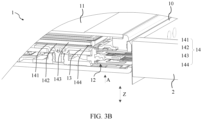
- FIG. 3B is a second partially enlarged view of the tablet computer 1 from a perspective of a sectional view according to an embodiment of this application.
- the tablet computer 1 in this embodiment of this application includes a middle frame 10 and a display module 11.
- the middle frame 10 is in a cuboid shape.
- a size of the middle frame 10 in a length direction (shown by an X direction in FIG. 1 ) is greater than a size of the middle frame 10 in a width direction (shown by a Y direction in FIG. 1 ).
- the display module 11 is disposed in the middle frame 10 in a thickness direction (shown by a Z direction in FIG. 1 ) of the tablet computer 1.
- a length direction, a width direction, and the thickness direction of the tablet computer 1 are perpendicular to each other.
- the display module 11 may be a flexible screen or a hard screen. This is not limited herein.
- the middle frame 10 and the display module 11 may be bonded together by using a sticky material (for example, a foam tape).
- a manner of connecting the middle frame 10 and the display module 11 is not limited to using the sticky material, provided that assembly can be implemented.
- a USB type C connector 12 is disposed inside an end in the length direction of the tablet computer 1, and the USB type C connector 12 is mounted in the middle frame 10 by using a compression structure 13 (for example, a compression steel sheet and a bolt).
- the USB type C connector 12 is used for a USB plug 2 to plug in, and may implement functions such as charging or externally connected to a headset.
- the display module 11 of the tablet computer 1 includes a backlight assembly 14, and the backlight assembly 14 in the display module 11 is disposed directly above the USB type C connector 12 in the thickness direction of the tablet computer 1.
- the backlight assembly 14 in the display module 11 in this embodiment of this application includes a back plate 141, a reflection sheet 142, and a light guide plate 143 that are stacked in the thickness direction.
- a direction in which the reflection sheet 142 points to the light guide plate 143 is a light emitting direction (shown by an A direction in FIG. 3A and FIG. 3B ) of the display module 11, and in the light emitting direction, the reflection sheet 142 is disposed between the back plate 141 and the light guide plate 143.
- the light guide plate 143 is adhered to the back plate 141 by using a fastening tape 144.
- the back plate 141 is disposed directly above the compression structure 13 of the USB type C connector 12.
- the display module 11 in this embodiment of this application can reflect light upward in the light emitting direction, so that the display module 11 displays a corresponding pattern.
- the light emitting direction is separately perpendicular to the length direction and the width direction, that is, the light emitting direction is parallel to the thickness direction.
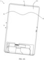
- FIG. 4A is a three-dimensional diagram of the display module of the tablet computer 1 according to an embodiment of this application
- FIG. 4A is a back view of the display module 11
- FIG. 4B is a partially enlarged view at a location that is on the back plate 141 and that corresponds to the USB type C connector 12 in FIG. 4A .
- the location that is on the back plate 141 and that corresponds to the USB type C connector 12 covers the compression structure 13 of the type C connector 12 (references may also be made to FIG. 3B ).
- the tablet computer 1 uses the standardized USB-type C connector 12, a thickness size of the USB-type C connector 12 cannot be changed (reduced). To reduce a thickness of an entire device, a security gap between the compression structure 13 of the USB-type C connector 12 and the display module 11 is inevitably compressed, and consequently, a potential risk of poor display exists during use of the tablet computer 1.
- the back plate 141 that is in the display module 11 and that is directly above the USB-type C connector 12 is provided with a notch.
- a notch 145 is provided at a location (shown by an A location in FIG. 5A and FIG. 5B ) that is on the back plate 141 and that corresponds to the compression structure 13 of the USB-type C connector 12.
- avoidance space between the compression structure 13 of the USB-type C connector 12 and the backlight assembly 14 in the Z direction (the thickness direction) is increased, that is, avoidance space between the compression structure 13 and the display module 11 in the Z direction (the thickness direction) is increased, so that a thickness of an entire device is reduced while a security gap is ensured.
- the notch 145 exposes the reflection sheet 142 on the backlight assembly 14 and the fastening tape 144 on the light guide plate 143.
- the notch 145 forms avoidance space in the Z direction, so that a thickness of the tablet computer 1 in the thickness direction can be reduced.
- the thickness of the tablet computer 1 is reduced, a security gap between the compression structure 13 of the USB-type C connector 12 and the backlight assembly 14 is ensured, a possibility of mutual interference between the compression structure 13 and the backlight assembly 14 in the Z direction is reduced, and a risk of poor display existing during use of the tablet computer 1 is reduced.
- the backlight assembly 14 in the display module 11 in this embodiment of this application further includes a light shielding member 146, and the light shielding member 146 is connected to the back plate 141 and is configured to wrap the notch 145.
- the following cases may be avoided: (1) Backlight is exposed at the provided notch, and a foreign object easily enters the backlight, causing display of defects such as a white spot, a white mass, or a foreign object. (2) Backlight is exposed at the provided notch, the backlight is emitted, and a defect of light leakage occurs in an entire device.
- the light shielding member 146 is added at the notch 145 on the back plate 141 to wrap the notch, to prevent a foreign object from entering the backlight assembly 14 and further shield light.
- the light shielding member 146 is a black Mylar sheet, that is, the black Mylar sheet is used to include the notch on the back plate 141.
- the back plate 141 is provided with the notch to avoid the compression structure 13 of the USB type C connector 12, and a thickness of an entire device is further reduced.
- dustproof Mylar is used for wrapping to eliminate a risk of foreign object entry.
- the light shielding member 146 includes a first part 1461, a second part 1462, and a third part 1463 that are connected.
- the display module 11 further includes cover glass 111, an optically clear adhesive 112, and a liquid crystal panel 113 that are stacked from top to bottom in the thickness direction, and the liquid crystal panel 113 is adhered to an adhesive frame 14a.
- the first part 1461 of the light shielding member 146 is connected to a side that is of the back plate 141 of the back plate assembly 14 in the display module 11 and that is away from the reflection sheet 142, the second part 1462 is connected to a side surface (for example, the adhesive frame 14a) of the backlight assembly 14, and the third part 1463 is connected to a side that is of the liquid crystal panel 113 and that faces the cover glass 111.
- the first part 1461 and the third part 1463 of the light shielding member 146 are spaced apart, and the second part 1462 is separately connected to the first part 1461 and the third part 1463. Therefore, the light shielding member 146 can wrap the notch 145 on the back plate 141, to prevent a foreign object from entering the backlight assembly 14 from the notch 145.
- FIG. 8A is a first three-dimensional diagram of the back plate 141 according to an embodiment of this application
- FIG. 8B is a second three-dimensional diagram of the back plate 141 according to an embodiment of this application
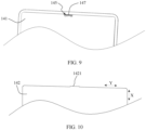
- FIG. 9 is a first partially enlarged view at the notch 145 on the back plate 141 according to an embodiment of this application.
- a convex lug 147 is disposed at the notch 145 on the back plate 141 in this embodiment of this application, and the convex lug 147 is configured to support the light guide plate 143 in the light emitting direction.
- the design of the convex lug 147 is used at the notch 145 on the back plate 141, which reduces a risk of film material deformation and cracking of light guide plate 143 in a falling process of the tablet computer 1.
- the convex lug 147 is further configured to support the reflection sheet 142 in the light emitting direction.
- the notch 145 on the back plate 141 includes a first sidewall 1451, a bottom wall 1452, and a second sidewall 1453 that are sequentially connected.
- the bottom wall 1452 extends in a width direction (as shown by a Y direction in FIG. 8B ), and the first sidewall 1451 and the second sidewall 1453 are disposed opposite to each other in the width direction and separately extend in a length direction (as shown by an X direction in FIG. 8B ).
- the convex lug 147 in this embodiment of this application extends in the length direction and protrudes from the bottom wall 1452 in the width direction.
- the convex lug 147 is separately spaced apart from the first sidewall 1451 and the second sidewall 1453 in the width direction. For example, intervals between the convex lug 147 and the first sidewall 1451 and the second sidewall 1453 are used to avoid the compression structure 13 of the USB type C connector 12. Therefore, the convex lug 147 at the notch 145 on the back plate 141 supports the light guide plate 143, and the notch 145 on the back plate 141 avoids the compression structure 13 of the USB type C connector 12, thereby ensuring a security gap.
- the convex lug 147 is separately shorter than the first sidewall 1451 and the second sidewall 1453 in the width direction. Through this disposing, the compression structure 13 of the USB type C connector 12 can also be avoided.
- FIG. 10 is a three-dimensional diagram of the reflection sheet 142 according to an embodiment of this application
- FIG. 11 is a three-dimensional diagram of the display module 11 according to an embodiment of this application
- FIG. 12 is a second partially enlarged view at the notch 145 on the back plate 141 according to an embodiment of this application.
- the light guide plate 143 drives the reflection sheet 142 to displace.
- the light guide plate 143 is fastened through the fastening tape 144, relative displacement between the light guide plate 143 and the reflection sheet 142 after falling cannot be completely avoided.
- the reflection sheet 142 is displaced, and the reflection sheet 142 moves relative to a location of the light guide plate 143.
- the notch 145 on the back plate 141 may be unable to reflect light upward, resulting in a local blackening visible to eyes. Consequently, a display problem may occur in the display module 11 of the tablet computer 1.
- there is no back adhesive to adhere the reflection sheet 142 to the back plate 141 there is no back adhesive to adhere the reflection sheet 142 to the back plate 141, and problems such as displacement and wrinkles easily occur during falling, resulting in abnormal display.
- a protrusion 1421 is disposed at a location that is on the reflection sheet 142 and that corresponds to the notch 145, and in the light emitting direction, projections of the reflection sheet 142 and the protrusion 1421 at least partially cover a projection of the notch 145. That is, the reflection sheet 142 in this embodiment of this application is designed in an irregular shape, and the reflection sheet 142 protrudes locally at the provided notch.
- a protruding part (that is, the protrusion 1421) on the reflection sheet 142 can still cover the notch (that is, the notch 145) on the back plate 141, so that the reflection sheet 142 provides sufficient reflected light, and no abnormal display occurs.
- a reflection back adhesive at the provided notch on the back plate 141 may be removed, to design the reflection sheet 142 in the irregular shape. Only an appearance shape of the reflection sheet 142 is optimized, and there is no additional fixture costs.
- the projections of the reflection sheet 142 and the protrusion 1421 completely cover the projection of the notch 145.
- the protrusion 1421 on the reflection sheet 142 is disposed protruding from the convex lug 147.
- the protrusion 1421 added to the reflection sheet 142 covers the entire notch 145 on the back plate 141, and the fastening tape 144 of the light guide plate 143 is not visible at the notch 145 on the back plate 141. This disposing helps the reflection panel provide sufficient reflected light.
- a white PET layer 148 is disposed at a location that is on the light shielding member 146 and that corresponds to the notch 145, and in the light emitting direction, a projection of the white PET layer 148 (polyethylene terephthalate) at least partially covers a projection of the notch 145.
- the white PET layer 148 is disposed on an inner wall of the dustproof Mylar that is added at the location of the provided notch. Even if the reflection sheet 142 is displaced during falling of the tablet computer 1, the white PET layer 148 can still provide enough reflected light.
- the projection of the white PET layer 148 completely covers the projection of the notch 145.
- the white PET layer 148 is disposed protruding from the convex lug 147.
- the back plate is provided with the notch to avoid the compression structure of the USB type C connector, so that a thickness of an entire device is further reduced.
- Black Mylar is added at the location of the provided notch, to prevent a foreign object from entering the back plate, and further shield light.
- Appearance of the provided notch on the back plate is optimized, and the convex lug design is locally added to support an inner film of the display module, thereby reducing a risk of film material deformation of and cracking of the light guide plate during falling.
- the reflection sheet is designed convexly or the white PET layer is disposed in the dustproof Mylar, to avoid a display problem caused by displacement of the reflection sheet during falling.
Landscapes
- Physics & Mathematics (AREA)
- General Physics & Mathematics (AREA)
- Optics & Photonics (AREA)
- Nonlinear Science (AREA)
- Mathematical Physics (AREA)
- Chemical & Material Sciences (AREA)
- Crystallography & Structural Chemistry (AREA)
- Devices For Indicating Variable Information By Combining Individual Elements (AREA)
Abstract
Description
- This application claims priority to
Chinese Patent Application No. 202222000605.3, filed with the China National Intellectual Property Administration on July 29, 2022 - This application relates to the field of electronic device technologies, and in particular, to a display module and an electronic device.
- With the development of science and technology and people's pursuit of aesthetics, lightness and thinness have become one of mainstream development directions of tablet products. Because the tablet product uses a standardized USB-type C connector, a thickness of the tablet product remains unchanged. To reduce a thickness of an entire device, a security gap between the USB-type C connector and a display module is inevitably compressed, and consequently, a potential risk of poor display exists during use of the tablet product.
- Embodiments of this application provide a display module. A back plate that is in the display module and that is directly above a USB-type C connector is provided with a notch to increase avoidance space in a Z direction, so that a thickness of an entire device is reduced while a security gap is ensured. A light shielding member is added at the notch on the back plate to wrap the notch, to prevent a foreign object from entering the display module and further shield light.
- To achieve the foregoing objective, the following technical solutions are used in embodiments of this application.
- According to a first aspect, an embodiment of this application provides a display module, including a back plate, a reflection sheet, a light guide plate, and a light shielding member. A direction in which the reflection sheet points to the light guide plate is a light emitting direction of the display module, and in the light emitting direction, the reflection sheet is disposed between the back plate and the light guide plate. In the light emitting direction, the back plate is disposed above a USB connector, and a notch is disposed at a location that is on the back plate and that corresponds to the USB connector. The light shielding member is connected to the back plate and wraps the notch.
- The back plate that is in the display module and that is directly above the USB-type C connector is provided with a notch to increase avoidance space in a Z direction, so that a thickness of an entire device is reduced while a security gap is ensured. The light shielding member is added at the notch on the back plate to wrap the notch, to prevent a foreign object from entering the display module and further shield light.
- In a possible implementation of the first aspect, the light shielding member includes a first part and a second part that are connected, the first part is connected to a side that is of the back plate and that is away from the reflection sheet, and the second part is connected to a side surface of the display module, to wrap the notch to prevent a foreign object from entering the display module from the notch.
- In a possible implementation of the first aspect, the light shielding member is a black Mylar sheet.
- In a possible implementation of the first aspect, a convex lug is disposed at the notch on the back plate, and the convex lug is configured to support the light guide plate in the light emitting direction.
- In a possible implementation of the first aspect, the convex lug is further configured to support the reflection sheet in the light emitting direction.
- In a possible implementation of the first aspect, the notch includes a first sidewall, a bottom wall, and a second sidewall that are sequentially connected;
- the bottom wall extends in a first direction;
- the first sidewall and the second sidewall are disposed opposite to each other in the first direction and separately extend in a second direction, the first direction and the second direction intersect, and the light emitting direction is separately perpendicular to the first direction and the second direction; and
- the convex lug extends in the first direction, and protrudes from the bottom wall in the second direction.
- In a possible implementation of the first aspect, in the first direction, the convex lug is separately spaced apart from the first sidewall and the second sidewall.
- In a possible implementation of the first aspect, intervals between the convex lug and the first sidewall and the second sidewall are used to avoid a compression structure of the USB connector.
- In a possible implementation of the first aspect, in the second direction, the convex lug is separately shorter than the first sidewall and the second sidewall, to avoid the compression structure of the USB connector.
- In a possible implementation of the first aspect, a protrusion is disposed at a location that is on the reflection sheet and that corresponds to the notch, and in the light emitting direction, projections of the reflection sheet and the protrusion at least partially cover a projection of the notch.
- In a possible implementation of the first aspect, in the light emitting direction, the projections of the reflection sheet and the protrusion completely cover the projection of the notch.
- In a possible implementation of the first aspect, a white PET layer is disposed at a location that is on the light shielding member and that corresponds to the notch, and in the light emitting direction, a projection of the white PET layer at least partially covers a projection of the notch.
- In a possible implementation of the first aspect, in the light emitting direction, the projection of the white PET layer in completely covers the projection of the notch.
- According to a second aspect, an embodiment of this application provides an electronic device, including: a USB connector, including a compression structure; and the display module described in any of the possible implementations of the first aspect, where in the light emitting direction of the display module, the back plate of the display module is disposed above the USB connector, and the notch is located above the compression structure of the USB connector.
-
-
FIG. 1 is a first three-dimensional diagram of a tablet computer according to some embodiments of this application; -
FIG. 2 is a partially enlarged view of a tablet computer from a perspective of a top view according to some embodiments of this application; -
FIG. 3A is a first partially enlarged view of a tablet computer from a perspective of a sectional view according to some embodiments of this application; -
FIG. 3B is a second partially enlarged view of a tablet computer from a perspective of a sectional view according to some embodiments of this application; -
FIG. 4A is a first three-dimensional diagram of a display module of a tablet computer according to some embodiments of this application; -
FIG. 4B is a first partially enlarged view taken along a B-B part inFIG. 4A according to some embodiments of this application; -
FIG. 5A is a second three-dimensional diagram of a display module of a tablet computer according to some embodiments of this application; -
FIG. 5B is a second partially enlarged view taken along a B-B part inFIG. 5A according to some embodiments of this application; -
FIG. 6A is a third partially enlarged view of a tablet computer from a perspective of a sectional view according to some embodiments of this application; -
FIG. 6B is a fourth partially enlarged view of a tablet computer from a perspective of a sectional view according to some embodiments of this application; -
FIG. 7A is a first partially enlarged view at a location that is on a back plate in a display module and that corresponds to a USB type C connector according to some embodiments of this application; -
FIG. 7B is a first partially enlarged view of a display module from a three-dimensional perspective according to some embodiments of this application; -
FIG. 8A is a first three-dimensional diagram of a back plate in a display module according to some embodiments of this application; -
FIG. 8B is a second three-dimensional diagram of a back plate in a display module according to some embodiments of this application; -
FIG. 9 is a second partially enlarged view at a location that is on a back plate in a display module and that corresponds to a USB type C connector according to some embodiments of this application; -
FIG. 10 is a partially enlarged view of a reflection sheet in a display module according to some embodiments of this application; -
FIG. 11 is a second partially enlarged view of a display module from a three-dimensional perspective according to some embodiments of this application; -
FIG. 12 is a third partially enlarged view at a location that is on a back plate in a display module and that corresponds to a USB type C connector according to some embodiments of this application; -
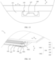
FIG. 13 is a fourth partially enlarged view at a location that is on a back plate in a display module and that corresponds to a USB type C connector according to some embodiments of this application; and -
FIG. 14 is a third partially enlarged view of a display module from a three-dimensional perspective according to some embodiments of this application. - The following describes specific implementations of this application in detail with reference to the accompanying drawings.
- Embodiments of this application provide a display module. A back plate that is in the display module and that is directly above a USB-type C connector is provided with a notch to increase avoidance space in a Z direction, so that a thickness of an entire device is reduced while a security gap is ensured.
- This application provides a display module used in an electronic device, and the display module uses a design in which a back plate is provided with a notch to avoid a compression structure of a USB connector (USB type C connector). Specifically, the electronic device includes but is not limited to an electronic device with a display module (for example, an LCD module) and a USB connector, such as a mobile phone, a tablet computer (tablet personal computer), an e-book reader, a laptop computer (laptop computer), a personal digital assistant (personal digital assistant, PDA), a personal computer, a notebook computer (notebook), a vehicle-mounted device, a wearable device (for example, a watch), or a box.
- For ease of description, an example in which the electronic device is a tablet computer is used for description in the following, and an example in which a USB connector is a USB type C connector is used for description. The following describes the tablet computer in this application by using specific embodiments.
-
FIG. 1 is a first three-dimensional diagram of atablet computer 1 according to an embodiment of this application,FIG. 2 is a partially enlarged view (adisplay module 11 is not shown) of thetablet computer 1 from a perspective of a top view according to an embodiment of this application,FIG. 3A is a first partially enlarged view of thetablet computer 1 from a perspective of a sectional view according to an embodiment of this application, andFIG. 3B is a second partially enlarged view of thetablet computer 1 from a perspective of a sectional view according to an embodiment of this application. - Referring to
FIG. 1 , thetablet computer 1 in this embodiment of this application includes amiddle frame 10 and adisplay module 11. For example, themiddle frame 10 is in a cuboid shape. To be specific, a size of themiddle frame 10 in a length direction (shown by an X direction inFIG. 1 ) is greater than a size of themiddle frame 10 in a width direction (shown by a Y direction inFIG. 1 ). Thedisplay module 11 is disposed in themiddle frame 10 in a thickness direction (shown by a Z direction inFIG. 1 ) of thetablet computer 1. For example, a length direction, a width direction, and the thickness direction of thetablet computer 1 are perpendicular to each other. - The
display module 11 may be a flexible screen or a hard screen. This is not limited herein. In this embodiment of this application, themiddle frame 10 and thedisplay module 11 may be bonded together by using a sticky material (for example, a foam tape). However, a manner of connecting themiddle frame 10 and thedisplay module 11 is not limited to using the sticky material, provided that assembly can be implemented. - As shown in
FIG. 2 , a USBtype C connector 12 is disposed inside an end in the length direction of thetablet computer 1, and the USBtype C connector 12 is mounted in themiddle frame 10 by using a compression structure 13 (for example, a compression steel sheet and a bolt). The USBtype C connector 12 is used for aUSB plug 2 to plug in, and may implement functions such as charging or externally connected to a headset. - As shown in
FIG. 3A andFIG. 3B , thedisplay module 11 of thetablet computer 1 includes abacklight assembly 14, and thebacklight assembly 14 in thedisplay module 11 is disposed directly above the USBtype C connector 12 in the thickness direction of thetablet computer 1. For example, thebacklight assembly 14 in thedisplay module 11 in this embodiment of this application includes aback plate 141, areflection sheet 142, and alight guide plate 143 that are stacked in the thickness direction. A direction in which thereflection sheet 142 points to thelight guide plate 143 is a light emitting direction (shown by an A direction inFIG. 3A andFIG. 3B ) of thedisplay module 11, and in the light emitting direction, thereflection sheet 142 is disposed between theback plate 141 and thelight guide plate 143. For example, thelight guide plate 143 is adhered to theback plate 141 by using afastening tape 144. In the light emitting direction, theback plate 141 is disposed directly above thecompression structure 13 of the USBtype C connector 12. Thedisplay module 11 in this embodiment of this application can reflect light upward in the light emitting direction, so that thedisplay module 11 displays a corresponding pattern. For example, the light emitting direction is separately perpendicular to the length direction and the width direction, that is, the light emitting direction is parallel to the thickness direction. -
FIG. 4A is a three-dimensional diagram of the display module of thetablet computer 1 according to an embodiment of this application,FIG. 4A is a back view of thedisplay module 11, andFIG. 4B is a partially enlarged view at a location that is on theback plate 141 and that corresponds to the USBtype C connector 12 inFIG. 4A . As shown inFIG. 4B , the location that is on theback plate 141 and that corresponds to the USBtype C connector 12 covers thecompression structure 13 of the type C connector 12 (references may also be made toFIG. 3B ). - Because the
tablet computer 1 uses the standardized USB-type C connector 12, a thickness size of the USB-type C connector 12 cannot be changed (reduced). To reduce a thickness of an entire device, a security gap between thecompression structure 13 of the USB-type C connector 12 and thedisplay module 11 is inevitably compressed, and consequently, a potential risk of poor display exists during use of thetablet computer 1. - Therefore, referring to
FIG. 5A andFIG. 5B , in this embodiment of this application, theback plate 141 that is in thedisplay module 11 and that is directly above the USB-type C connector 12 is provided with a notch. Specifically, anotch 145 is provided at a location (shown by an A location inFIG. 5A andFIG. 5B ) that is on theback plate 141 and that corresponds to thecompression structure 13 of the USB-type C connector 12. After this disposing, avoidance space between thecompression structure 13 of the USB-type C connector 12 and thebacklight assembly 14 in the Z direction (the thickness direction) is increased, that is, avoidance space between thecompression structure 13 and thedisplay module 11 in the Z direction (the thickness direction) is increased, so that a thickness of an entire device is reduced while a security gap is ensured. - As shown in
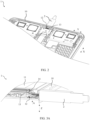
FIG. 6A andFIG. 6B , in the thickness direction (as shown by a Z direction inFIG. 6A andFIG. 6B ), there is a notch (that is, the notch 145) directly above thecompression structure 13 of the USB-type C connector 12. For example, thenotch 145 exposes thereflection sheet 142 on thebacklight assembly 14 and thefastening tape 144 on thelight guide plate 143. Thenotch 145 forms avoidance space in the Z direction, so that a thickness of thetablet computer 1 in the thickness direction can be reduced. To be specific, after the thickness of thetablet computer 1 is reduced, a security gap between thecompression structure 13 of the USB-type C connector 12 and thebacklight assembly 14 is ensured, a possibility of mutual interference between thecompression structure 13 and thebacklight assembly 14 in the Z direction is reduced, and a risk of poor display existing during use of thetablet computer 1 is reduced. - In some possible implementations, referring to
FIG. 7A andFIG. 7B , thebacklight assembly 14 in thedisplay module 11 in this embodiment of this application further includes alight shielding member 146, and thelight shielding member 146 is connected to theback plate 141 and is configured to wrap thenotch 145. After thelight shielding member 146 is disposed, the following cases may be avoided: (1) Backlight is exposed at the provided notch, and a foreign object easily enters the backlight, causing display of defects such as a white spot, a white mass, or a foreign object. (2) Backlight is exposed at the provided notch, the backlight is emitted, and a defect of light leakage occurs in an entire device. In other words, after thelight shielding member 146 is disposed, thelight shielding member 146 is added at thenotch 145 on theback plate 141 to wrap the notch, to prevent a foreign object from entering thebacklight assembly 14 and further shield light. - For example, the
light shielding member 146 is a black Mylar sheet, that is, the black Mylar sheet is used to include the notch on theback plate 141. In other words, theback plate 141 is provided with the notch to avoid thecompression structure 13 of the USBtype C connector 12, and a thickness of an entire device is further reduced. In addition, dustproof Mylar is used for wrapping to eliminate a risk of foreign object entry. - Still referring to
FIG. 7B , thelight shielding member 146 includes afirst part 1461, asecond part 1462, and athird part 1463 that are connected. Thedisplay module 11 further includescover glass 111, an opticallyclear adhesive 112, and aliquid crystal panel 113 that are stacked from top to bottom in the thickness direction, and theliquid crystal panel 113 is adhered to anadhesive frame 14a. Thefirst part 1461 of thelight shielding member 146 is connected to a side that is of theback plate 141 of theback plate assembly 14 in thedisplay module 11 and that is away from thereflection sheet 142, thesecond part 1462 is connected to a side surface (for example, theadhesive frame 14a) of thebacklight assembly 14, and thethird part 1463 is connected to a side that is of theliquid crystal panel 113 and that faces thecover glass 111. In other words, in the thickness direction (as shown by a Z direction inFIG. 7B ), thefirst part 1461 and thethird part 1463 of thelight shielding member 146 are spaced apart, and thesecond part 1462 is separately connected to thefirst part 1461 and thethird part 1463. Therefore, thelight shielding member 146 can wrap thenotch 145 on theback plate 141, to prevent a foreign object from entering thebacklight assembly 14 from thenotch 145. -
FIG. 8A is a first three-dimensional diagram of theback plate 141 according to an embodiment of this application,FIG. 8B is a second three-dimensional diagram of theback plate 141 according to an embodiment of this application, andFIG. 9 is a first partially enlarged view at thenotch 145 on theback plate 141 according to an embodiment of this application. - As described above, because the
back plate 141 is provided with thenotch 145, after thenotch 145 is disposed, there is no Z-direction support and protection for an internal film material at the provided notch. During a reliability test of an entire device, for example, during falling, thelight guide plate 143 may swing and hit an external structural member, which is prone to cause a problem of cracking of thelight guide plate 143. Therefore, in some possible implementations, as shown inFIG. 8B andFIG. 9 , aconvex lug 147 is disposed at thenotch 145 on theback plate 141 in this embodiment of this application, and theconvex lug 147 is configured to support thelight guide plate 143 in the light emitting direction. The design of theconvex lug 147 is used at thenotch 145 on theback plate 141, which reduces a risk of film material deformation and cracking oflight guide plate 143 in a falling process of thetablet computer 1. - In some possible implementations, the
convex lug 147 is further configured to support thereflection sheet 142 in the light emitting direction. - A specific shape of the
convex lug 147 is not limited in this application. In some possible implementations, referring toFIG. 8B , thenotch 145 on theback plate 141 includes afirst sidewall 1451, abottom wall 1452, and asecond sidewall 1453 that are sequentially connected. Thebottom wall 1452 extends in a width direction (as shown by a Y direction inFIG. 8B ), and thefirst sidewall 1451 and thesecond sidewall 1453 are disposed opposite to each other in the width direction and separately extend in a length direction (as shown by an X direction inFIG. 8B ). Theconvex lug 147 in this embodiment of this application extends in the length direction and protrudes from thebottom wall 1452 in the width direction. - For example, the
convex lug 147 is separately spaced apart from thefirst sidewall 1451 and thesecond sidewall 1453 in the width direction. For example, intervals between theconvex lug 147 and thefirst sidewall 1451 and thesecond sidewall 1453 are used to avoid thecompression structure 13 of the USBtype C connector 12. Therefore, theconvex lug 147 at thenotch 145 on theback plate 141 supports thelight guide plate 143, and thenotch 145 on theback plate 141 avoids thecompression structure 13 of the USBtype C connector 12, thereby ensuring a security gap. - In some possible implementations, the
convex lug 147 is separately shorter than thefirst sidewall 1451 and thesecond sidewall 1453 in the width direction. Through this disposing, thecompression structure 13 of the USBtype C connector 12 can also be avoided. -
FIG. 10 is a three-dimensional diagram of thereflection sheet 142 according to an embodiment of this application,FIG. 11 is a three-dimensional diagram of thedisplay module 11 according to an embodiment of this application, andFIG. 12 is a second partially enlarged view at thenotch 145 on theback plate 141 according to an embodiment of this application. - In a mechanical reliability process of the
tablet computer 1, thelight guide plate 143 drives thereflection sheet 142 to displace. Although thelight guide plate 143 is fastened through thefastening tape 144, relative displacement between thelight guide plate 143 and thereflection sheet 142 after falling cannot be completely avoided. After a falling test, thereflection sheet 142 is displaced, and thereflection sheet 142 moves relative to a location of thelight guide plate 143. Thenotch 145 on theback plate 141 may be unable to reflect light upward, resulting in a local blackening visible to eyes. Consequently, a display problem may occur in thedisplay module 11 of thetablet computer 1. In addition, at the provided notch, there is no back adhesive to adhere thereflection sheet 142 to theback plate 141, and problems such as displacement and wrinkles easily occur during falling, resulting in abnormal display. - Therefore, referring to
FIG. 10 to FIG. 12 , in this embodiment of this application, aprotrusion 1421 is disposed at a location that is on thereflection sheet 142 and that corresponds to thenotch 145, and in the light emitting direction, projections of thereflection sheet 142 and theprotrusion 1421 at least partially cover a projection of thenotch 145. That is, thereflection sheet 142 in this embodiment of this application is designed in an irregular shape, and thereflection sheet 142 protrudes locally at the provided notch. Even if thereflection sheet 142 is displaced during falling of thetablet computer 1, a protruding part (that is, the protrusion 1421) on thereflection sheet 142 can still cover the notch (that is, the notch 145) on theback plate 141, so that thereflection sheet 142 provides sufficient reflected light, and no abnormal display occurs. For example, a reflection back adhesive at the provided notch on theback plate 141 may be removed, to design thereflection sheet 142 in the irregular shape. Only an appearance shape of thereflection sheet 142 is optimized, and there is no additional fixture costs. - For example, in the light emitting direction, the projections of the
reflection sheet 142 and theprotrusion 1421 completely cover the projection of thenotch 145. For example, in the length direction, theprotrusion 1421 on thereflection sheet 142 is disposed protruding from theconvex lug 147. Theprotrusion 1421 added to thereflection sheet 142 covers theentire notch 145 on theback plate 141, and thefastening tape 144 of thelight guide plate 143 is not visible at thenotch 145 on theback plate 141. This disposing helps the reflection panel provide sufficient reflected light. - In addition, in some possible implementations, referring to
FIG. 13 and FIG. 14 , awhite PET layer 148 is disposed at a location that is on thelight shielding member 146 and that corresponds to thenotch 145, and in the light emitting direction, a projection of the white PET layer 148 (polyethylene terephthalate) at least partially covers a projection of thenotch 145. Thewhite PET layer 148 is disposed on an inner wall of the dustproof Mylar that is added at the location of the provided notch. Even if thereflection sheet 142 is displaced during falling of thetablet computer 1, thewhite PET layer 148 can still provide enough reflected light. In other words, light may be reflected upward through thewhite PET layer 148, a display effect is not affected, and no abnormal display occurs. In other words, when thewhite PET layer 148 is disposed in the dustproof Mylar, a display problem caused by displacement of thereflection sheet 142 during falling can also be avoided. - For example, in the light emitting direction, the projection of the
white PET layer 148 completely covers the projection of thenotch 145. For example, in the length direction, thewhite PET layer 148 is disposed protruding from theconvex lug 147. - In summary, in the display module in the embodiments of this application, the back plate is provided with the notch to avoid the compression structure of the USB type C connector, so that a thickness of an entire device is further reduced. Black Mylar is added at the location of the provided notch, to prevent a foreign object from entering the back plate, and further shield light. Appearance of the provided notch on the back plate is optimized, and the convex lug design is locally added to support an inner film of the display module, thereby reducing a risk of film material deformation of and cracking of the light guide plate during falling. For a display problem caused by displacement of the reflection sheet, the reflection sheet is designed convexly or the white PET layer is disposed in the dustproof Mylar, to avoid a display problem caused by displacement of the reflection sheet during falling.
Claims (14)
- A display module, comprising a back plate, a reflection sheet, a light guide plate, and a light shielding member, whereina direction in which the reflection sheet points to the light guide plate is a light emitting direction of the display module, and in the light emitting direction, the reflection sheet is disposed between the back plate and the light guide plate;in the light emitting direction, the back plate is configured to be disposed above a USB connector, and a notch is disposed at a location that is on the back plate and that corresponds to the USB connector; andthe light shielding member is connected to the back plate and wraps the notch.
- The display module according to claim 1, wherein the light shielding member comprises a first part and a second part that are connected, the first part is connected to a side that is of the back plate and that is away from the reflection sheet, and the second part is connected to a side surface of the display module, to wrap the notch to prevent a foreign object from entering the display module from the notch.
- The display module according to claim 1, wherein the light shielding member is a black Mylar sheet.
- The display module according to any one of claims 1 to 3, wherein a convex lug is disposed at the notch on the back plate, and the convex lug is configured to support the light guide plate in the light emitting direction.
- The display module according to claim 4, wherein the convex lug is further configured to support the reflection sheet in the light emitting direction.
- The display module according to claim 4, wherein the notch comprises a first sidewall, a bottom wall, and a second sidewall that are sequentially connected;the bottom wall extends in a first direction;the first sidewall and the second sidewall are disposed opposite to each other in the first direction and separately extend in a second direction, the first direction and the second direction intersect, and the light emitting direction is separately perpendicular to the first direction and the second direction; andthe convex lug extends in the first direction, and protrudes from the bottom wall in the second direction.
- The display module according to claim 6, wherein in the first direction, the convex lug is separately spaced apart from the first sidewall and the second sidewall.
- The display module according to claim 7, wherein intervals between the convex lug and the first sidewall and the second sidewall are used to avoid a compression structure of the USB connector.
- The display module according to any one of claims 6 to 8, wherein in the second direction, the convex lug is separately shorter than the first sidewall and the second sidewall, to avoid the compression structure of the USB connector.
- The display module according to any one of claims 1 to 3 and 5 to 8, wherein a protrusion is disposed at a location that is on the reflection sheet and that corresponds to the notch, and in the light emitting direction, projections of the reflection sheet and the protrusion at least partially cover a projection of the notch.
- The display module according to claim 10, wherein in the light emitting direction, the projections of the reflection sheet and the protrusion completely cover the projection of the notch.
- The display module according to any one of claims 1 to 3 and 5 to 8, wherein a white PET layer is disposed at a location that is on the light shielding member and that corresponds to the notch, and in the light emitting direction, a projection of the white PET layer at least partially covers a projection of the notch.
- The display module according to claim 12, wherein in the light emitting direction, the projection of the white PET layer completely covers the projection of the notch.
- An electronic device, comprising:a USB connector, comprising a compression structure; andthe display module according to any one of claims 1 to 13, wherein in the light emitting direction of the display module, the back plate of the display module is disposed above the USB connector, and the notch is located above the compression structure of the USB connector.
Applications Claiming Priority (2)
| Application Number | Priority Date | Filing Date | Title |
|---|---|---|---|
| CN202222000605.3U CN218383546U (en) | 2022-07-29 | 2022-07-29 | Display module assembly and electronic equipment |
| PCT/CN2023/089850 WO2024021701A1 (en) | 2022-07-29 | 2023-04-21 | Display module and electronic device |
Publications (2)
| Publication Number | Publication Date |
|---|---|
| EP4468072A1 true EP4468072A1 (en) | 2024-11-27 |
| EP4468072A4 EP4468072A4 (en) | 2025-07-30 |
Family
ID=84965715
Family Applications (1)
| Application Number | Title | Priority Date | Filing Date |
|---|---|---|---|
| EP23844917.7A Pending EP4468072A4 (en) | 2022-07-29 | 2023-04-21 | DISPLAY MODULE AND ELECTRONIC DEVICE |
Country Status (4)
| Country | Link |
|---|---|
| US (1) | US20250180799A1 (en) |
| EP (1) | EP4468072A4 (en) |
| CN (1) | CN218383546U (en) |
| WO (1) | WO2024021701A1 (en) |
Families Citing this family (1)
| Publication number | Priority date | Publication date | Assignee | Title |
|---|---|---|---|---|
| CN218383546U (en) * | 2022-07-29 | 2023-01-24 | 荣耀终端有限公司 | Display module assembly and electronic equipment |
Family Cites Families (10)
| Publication number | Priority date | Publication date | Assignee | Title |
|---|---|---|---|---|
| US6361357B1 (en) * | 2000-04-13 | 2002-03-26 | 3Com Corporation | Remotely illuminated electronic connector for improving viewing of status indicators |
| KR101393927B1 (en) * | 2012-08-16 | 2014-05-12 | 기아자동차주식회사 | Multimedia Jack For Vehicle With Lighting Apparatus |
| US9928762B2 (en) * | 2012-09-28 | 2018-03-27 | Apple Inc. | Electronic devices with flexible circuit light shields |
| US9921360B2 (en) * | 2013-12-24 | 2018-03-20 | Sharp Kabushiki Kaisha | Illumination device and display device |
| CN205160659U (en) * | 2015-09-18 | 2016-04-13 | 镇江华科数码有限公司 | Clear digital television of ultra -thin superelevation |
| CN206193608U (en) * | 2016-10-31 | 2017-05-24 | 深圳市垦鑫达科技有限公司 | Portable electronic device |
| CN110579906B (en) * | 2019-09-19 | 2022-01-28 | 京东方科技集团股份有限公司 | Backlight module and display device |
| CN210982992U (en) * | 2019-12-16 | 2020-07-10 | 中强光电股份有限公司 | Backlight module |
| CN112578860A (en) * | 2020-12-23 | 2021-03-30 | Oppo广东移动通信有限公司 | Electronic equipment |
| CN218383546U (en) * | 2022-07-29 | 2023-01-24 | 荣耀终端有限公司 | Display module assembly and electronic equipment |
-
2022
- 2022-07-29 CN CN202222000605.3U patent/CN218383546U/en active Active
-
2023
- 2023-04-21 US US18/843,538 patent/US20250180799A1/en active Pending
- 2023-04-21 EP EP23844917.7A patent/EP4468072A4/en active Pending
- 2023-04-21 WO PCT/CN2023/089850 patent/WO2024021701A1/en not_active Ceased
Also Published As
| Publication number | Publication date |
|---|---|
| CN218383546U (en) | 2023-01-24 |
| WO2024021701A1 (en) | 2024-02-01 |
| EP4468072A4 (en) | 2025-07-30 |
| US20250180799A1 (en) | 2025-06-05 |
Similar Documents
| Publication | Publication Date | Title |
|---|---|---|
| CN108628043B (en) | Screen components and electronic devices | |
| US7126650B2 (en) | Illumination unit and liquid crystal display apparatus comprising same | |
| CN214587755U (en) | Flexible display module and electronic equipment | |
| US9377174B2 (en) | Display device | |
| JP6616448B2 (en) | Display device | |
| TW201317674A (en) | Information processing apparatus | |
| US20220386491A1 (en) | Electronic device including waterproof structure | |
| EP3089140B1 (en) | Display apparatus | |
| CN113630486B (en) | Electronic equipment and displays | |
| KR101386566B1 (en) | Liquid crystal display device | |
| US20250180799A1 (en) | Display module and electronic device | |
| US20230263004A1 (en) | Electronic Devices Having Curved Displays With Supporting Frames | |
| CN110275337A (en) | Display device | |
| US20120019483A1 (en) | Optical touch-controlled display device and its optical touch-controlled module | |
| JP5518536B2 (en) | Electro-optical device and electronic apparatus | |
| KR100493616B1 (en) | Liquid crystal display | |
| JP2007065855A (en) | Display device with touch panel | |
| CN216391092U (en) | Cover plate and display device | |
| US12222603B2 (en) | Display module structure and display device | |
| CN114236894A (en) | Display device and mobile terminal | |
| KR101820282B1 (en) | Display apparatus | |
| TWI472851B (en) | Display, backlight module, and frame structure thereof | |
| JP2010085549A (en) | Liquid crystal device and electronic apparatus | |
| CN220357376U (en) | Display device and electronic apparatus | |
| CN223413818U (en) | An electronic device |
Legal Events
| Date | Code | Title | Description |
|---|---|---|---|
| STAA | Information on the status of an ep patent application or granted ep patent |
Free format text: STATUS: THE INTERNATIONAL PUBLICATION HAS BEEN MADE |
|
| PUAI | Public reference made under article 153(3) epc to a published international application that has entered the european phase |
Free format text: ORIGINAL CODE: 0009012 |
|
| STAA | Information on the status of an ep patent application or granted ep patent |
Free format text: STATUS: REQUEST FOR EXAMINATION WAS MADE |
|
| 17P | Request for examination filed |
Effective date: 20240820 |
|
| AK | Designated contracting states |
Kind code of ref document: A1 Designated state(s): AL AT BE BG CH CY CZ DE DK EE ES FI FR GB GR HR HU IE IS IT LI LT LU LV MC ME MK MT NL NO PL PT RO RS SE SI SK SM TR |
|
| A4 | Supplementary search report drawn up and despatched |
Effective date: 20250627 |
|
| RIC1 | Information provided on ipc code assigned before grant |
Ipc: G02F 1/1333 20060101AFI20250623BHEP Ipc: G09F 9/30 20060101ALI20250623BHEP Ipc: G09F 9/35 20060101ALI20250623BHEP Ipc: F21V 8/00 20060101ALI20250623BHEP Ipc: G02F 1/1335 20060101ALI20250623BHEP |
|
| DAV | Request for validation of the european patent (deleted) | ||
| DAX | Request for extension of the european patent (deleted) | ||
| GRAP | Despatch of communication of intention to grant a patent |
Free format text: ORIGINAL CODE: EPIDOSNIGR1 |
|
| STAA | Information on the status of an ep patent application or granted ep patent |
Free format text: STATUS: GRANT OF PATENT IS INTENDED |
|
| INTG | Intention to grant announced |
Effective date: 20260112 |
|
| GRAS | Grant fee paid |
Free format text: ORIGINAL CODE: EPIDOSNIGR3 |
|
| GRAA | (expected) grant |
Free format text: ORIGINAL CODE: 0009210 |
|
| STAA | Information on the status of an ep patent application or granted ep patent |
Free format text: STATUS: THE PATENT HAS BEEN GRANTED |