EP4467814A1 - Centrifugal blower and air conditioning device - Google Patents
Centrifugal blower and air conditioning device Download PDFInfo
- Publication number
- EP4467814A1 EP4467814A1 EP22920308.8A EP22920308A EP4467814A1 EP 4467814 A1 EP4467814 A1 EP 4467814A1 EP 22920308 A EP22920308 A EP 22920308A EP 4467814 A1 EP4467814 A1 EP 4467814A1
- Authority
- EP
- European Patent Office
- Prior art keywords
- plate
- air
- fan
- sending device
- extension plate
- Prior art date
- Legal status (The legal status is an assumption and is not a legal conclusion. Google has not performed a legal analysis and makes no representation as to the accuracy of the status listed.)
- Withdrawn
Links
Images






Classifications
-
- F—MECHANICAL ENGINEERING; LIGHTING; HEATING; WEAPONS; BLASTING
- F04—POSITIVE - DISPLACEMENT MACHINES FOR LIQUIDS; PUMPS FOR LIQUIDS OR ELASTIC FLUIDS
- F04D—NON-POSITIVE-DISPLACEMENT PUMPS
- F04D29/00—Details, component parts, or accessories
- F04D29/40—Casings; Connections of working fluid
- F04D29/42—Casings; Connections of working fluid for radial or helico-centrifugal pumps
- F04D29/4206—Casings; Connections of working fluid for radial or helico-centrifugal pumps especially adapted for elastic fluid pumps
- F04D29/422—Discharge tongues
-
- F—MECHANICAL ENGINEERING; LIGHTING; HEATING; WEAPONS; BLASTING
- F04—POSITIVE - DISPLACEMENT MACHINES FOR LIQUIDS; PUMPS FOR LIQUIDS OR ELASTIC FLUIDS
- F04D—NON-POSITIVE-DISPLACEMENT PUMPS
- F04D29/00—Details, component parts, or accessories
- F04D29/40—Casings; Connections of working fluid
- F04D29/42—Casings; Connections of working fluid for radial or helico-centrifugal pumps
- F04D29/4206—Casings; Connections of working fluid for radial or helico-centrifugal pumps especially adapted for elastic fluid pumps
- F04D29/4226—Fan casings
-
- F—MECHANICAL ENGINEERING; LIGHTING; HEATING; WEAPONS; BLASTING
- F04—POSITIVE - DISPLACEMENT MACHINES FOR LIQUIDS; PUMPS FOR LIQUIDS OR ELASTIC FLUIDS
- F04D—NON-POSITIVE-DISPLACEMENT PUMPS
- F04D17/00—Radial-flow pumps, e.g. centrifugal pumps; Helico-centrifugal pumps
- F04D17/08—Centrifugal pumps
- F04D17/10—Centrifugal pumps for compressing or evacuating
-
- F—MECHANICAL ENGINEERING; LIGHTING; HEATING; WEAPONS; BLASTING
- F24—HEATING; RANGES; VENTILATING
- F24F—AIR-CONDITIONING; AIR-HUMIDIFICATION; VENTILATION; USE OF AIR CURRENTS FOR SCREENING
- F24F1/00—Room units for air-conditioning, e.g. separate or self-contained units or units receiving primary air from a central station
- F24F1/0007—Indoor units, e.g. fan coil units
- F24F1/0018—Indoor units, e.g. fan coil units characterised by fans
- F24F1/0022—Centrifugal or radial fans
Definitions
- the present disclosure relates to a centrifugal air-sending device having a scroll casing and to an air-conditioning apparatus.
- An existing centrifugal air-sending device includes a fan having a main plate that is disc-shaped, a plurality of blades located around a periphery of the main plate, and a side plate that is located such that the side plate faces the main plate, and fixes the blades. Further, to raise the pressure of airflow generated by the rotation of the fan and flowing out from the blades, the existing centrifugal air-sending device includes a scroll casing that is spiral-shaped, has a tongue portion from which an air trunk starts to be gradually expanded, and guides the airflow to a discharge port.
- the air trunk is abruptly expanded in the vicinity of the discharge port, there is a difference in direction of the airflow between one portion of the fan that is closer to the main plate than is another portion of the fan that is closer to the side plate than is the one portion and the other portion. Therefore, in the existing centrifugal air-sending device, a portion of the airflow that flows through the other portion closer to the side plate does not flow toward the discharge port but flows backward into the scroll casing while sucking in air from around the discharge port. This may reduce the volume of air and increase noise.
- Patent Literature 1 Japanese Unexamined Patent Application Publication No. 2020-029838
- the centrifugal air-sending device of Patent Literature 1 when the centrifugal air-sending device of Patent Literature 1 is installed in a narrow space, the distance from the tongue portion to a discharge-port end cannot be lengthened. Therefore, in a state in which the wall thickness of the tongue portion is great as in the case of the centrifugal air-sending device of Patent Literature 1, the centrifugal air-sending device may not be able to raise pressure inside the scroll casing, as the air trunk cannot be sufficiently expanded, and may reduce the volume of air that is discharged, as the discharge port has a narrow opening.
- the present disclosure is made to solve the above problems and has as an object to provide a centrifugal air-sending device and an air-conditioning apparatus that, even when installed in a narrow space, can raise pressure inside a scroll casing while preventing backflow of airflow in the scroll casing and control a reduction in the volume of air that is discharged.
- a centrifugal air-sending device includes a fan and a scroll casing.
- the fan has a main plate that is disc-shaped, a plurality of blades located around a periphery of the main plate, and a side plate that is ring-shaped, is located such that the side plate faces the main plate, and fixes ends of the plurality of blades that are opposite to the main plate.
- the scroll casing has a peripheral wall that is spiral-shaped and at least one side wall that has a bell mouth that forms an air inlet that communicates with a space surrounded by the main plate and the plurality of blades.
- the scroll casing forms a discharge port through which airflow generated by the fan is discharged.
- the scroll casing houses the fan.
- the scroll casing has a tongue portion and an extension plate.
- the tongue portion forms a curved surface at a winding-start portion of the peripheral wall that is closer to a rotation axis of the fan than are other portions of the peripheral wall.
- the tongue portion guides the airflow generated by the fan to the discharge port.
- the extension plate is plate-shaped, projects from the tongue portion, is spaced apart from the fan, and extends from the tongue portion along an outer periphery of the fan.
- the extension plate has one portion that is closer to the side plate than is another portion of the extension plate that is closer to the main plate than is the one portion. The one portion is formed longer than the other portion in a circumferential direction of the fan.
- the extension plate has a distal end portion that extends in a direction of projection in which the extension plate projects from the tongue portion.
- the distal end portion has an extreme distal end that is located at a boundary between the distal end portion and the at least one side wall.
- the scroll casing has, in a case in which the scroll casing is projected in an axial direction of the rotation axis, a tongue-portion-side end that is located in a discharge-port edge that is a portion that corresponds to the discharge port.
- the tongue-portion-side end is an end that is closer to the tongue portion than is another end of the discharge-port edge.
- the tongue-portion-side end is located opposite to the extreme distal end in the circumferential direction across a reference line drawn perpendicular to the discharge-port edge from the rotation axis.
- An air-conditioning apparatus includes the centrifugal air-sending device described above and a heat exchanger through which air caused by the centrifugal air-sending device to flow passes.
- the centrifugal air-sending device has an extension plate that is plate-shaped, projects from the tongue portion, is spaced apart from the fan, and extends from the tongue portion along an outer periphery of the fan.
- the extension plate has one portion that is closer to the side plate than is another portion of the extension plate that is closer to the main plate than is the one portion.
- the one portion is formed longer than the other portion in a circumferential direction of the fan.
- the one portion of the extension plate reduces backflow of the airflow from around the discharge port toward the inside of the scroll casing, whereby the airflow can be smoothly guided from the one portion to the discharge port.
- the formation of the extension plate in the shape of a plate makes it possible to ensure the distance between the extension plate and the discharge port and sufficiently ensure an air trunk, thus making it possible to surely raise pressure inside the scroll casing.
- the extension plate has a distal end portion that extends in a direction of projection in which the extension plate projects from the tongue portion.
- the distal end portion has an extreme distal end that is located at a boundary between the distal end portion and the at least one side wall.
- the tongue-portion-side end is located opposite to the extreme distal end in the circumferential direction across a reference line drawn perpendicular to the discharge-port edge from the rotation axis. Therefore, the centrifugal air-sending device can ensure the opening area of the discharge port and control a reduction in the volume of air that is discharged.
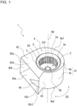
- Fig. 1 is a perspective view of a centrifugal air-sending device 1 according to Embodiment 1.
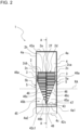
- Fig. 2 is a side view of the centrifugal air-sending device 1 in Fig. 1 as seen from a discharge port 42a.
- Fig. 3 is a schematic view of the centrifugal air-sending device 1 according to Embodiment 1 as seen in an axial direction of a rotation axis RA at a position in the centrifugal air-sending device 1 indicated by line A-A in Fig. 2 . It should be noted that Fig.
- FIG. 3 is also a conceptual diagram in which a scroll casing 4 of the centrifugal air-sending device 1 of Embodiment 1 is projected in the axial direction of the rotation axis RA.
- a circumferential direction CD indicated by arrows in Figs. 1 and 3 indicates a circumferential direction of a fan 2.
- a basic structure of the centrifugal air-sending device 1 is described with reference to Figs. 1 to 3 .
- the centrifugal air-sending device 1 is a multi-blade centrifugal air-sending device, and includes a fan 2, which generates airflow, and a scroll casing 4 in which the fan 2 is housed.
- the centrifugal air-sending device 1 is a double-suction centrifugal air-sending device into which air is sucked through both ends of the scroll casing 4 in an axial direction of the rotation axis RA of the fan 2, which is virtually drawn.
- the fan 2 is a centrifugal fan.
- the fan 2 is connected to a motor (not illustrated) having a drive shaft.
- the fan 2 is driven into rotation by the motor.
- the rotation generates a centrifugal force with which the fan 2 forcibly sends out air outward in radial directions.
- the fan 2 is rotated, for example, by the motor in a direction of rotation R indicated by an arrow.
- the fan 2 has a main plate 2a, which is disc-shaped, a side plate 2c, which is ring-shaped, and a plurality of blades 2d arranged around a periphery 2a1 of the main plate 2a in a radial manner around the rotation axis RA.
- the fan 2 is formed in the shape of a circular cylinder by the plurality of blades 2d arranged on the main plate 2a.
- the fan 2 has a fan air inlet 2e formed in a portion of the fan 2 that is opposite to the main plate 2a and closer to the side plate 2c than are other portions of the fan 2 in the axial direction of the rotation axis RA.
- the fan air inlet 2e allows gas to flow into a space surrounded by the main plate 2a and the plurality of blades 2d.
- the main plate 2a needs only be in the shape of a plate, and may for example have a non-disc shape such as a polygonal shape. Further, the main plate 2a may be formed such that the thickness of the main plate 2a increases toward the center in a radial directions that start from the rotation axis RA as a radial center, or may be formed such that the thickness is uniform in radial directions that start from the rotation axis RA as a radial center. Further, instead of being formed by one plate-shaped element, the main plate 2a may be formed by a plurality of plate-shaped elements integrally fixed to each other. It should be noted that the radial directions that start from the rotation axis RA as a radial center are each a direction perpendicular to the axial direction of the rotation axis RA.
- a boss portion 2b to which the drive shaft of the motor is connected is provided at a central part of the main plate 2a.
- the boss portion 2b has a shaft hole into which the drive shaft of the motor is inserted.
- the boss portion 2b is formed in a circular columnar shape, the shape of the boss portion 2b is not limited to the circular columnar shape.
- the boss portion 2b needs only be formed in a columnar shape, and may for example be formed in a polygonal columnar shape.
- the main plate 2a is driven into rotation by the motor by use of the boss portion 2b in between.
- the fan 2 has the side plate 2c, which is ring-shaped and is attached to ends of the plurality of blades 2d that are opposite to the main plate 2a in the axial direction of the rotation axis RA.
- the side plate 2c fixes the ends of the plurality of blades 2d that are opposite to the main plate 2a.
- the side plate 2c is provided at an outer circumferential face 2f of the fan 2, and in the fan 2, is located such that the side plate 2c faces the main plate 2a.
- the side plate 2c is provided at outer portions of the blades 2d in radial directions that start from the rotation axis RA as a radial center.
- the side plate 2c may be provided at distal end portions of the plurality of blades 2d that project from the main plate 2a in a direction of the rotation axis RA.
- the side plate 2c joins the plurality of blades 2d with each other, thereby maintaining a positional relationship between the distal end of each blade 2d and the distal end of the other blade 2d and reinforcing the plurality of blades 2d.
- the side plate 2c includes a first side plate 2ca, which is ring-shaped and is located such that the first side plate 2ca faces the main plate 2a, and a second side plate 2cb, which is ring-shaped and is located such that the second side plate 2cb faces the main plate 2a and is located opposite to the first side plate 2ca across the main plate 2a.
- the term "side plate 2c" is a generic name for the first side plate 2ca and the second side plate 2cb, and the fan 2 has the first side plate 2ca at one side of the main plate 2a in the axial direction of the rotation axis RA and has the second side plate 2cb at the other side.
- the first side plate 2ca is located at the right side of the main plate 2a and the second side plate 2cb is located at the left side of the main plate 2a, the first side plate 2ca and the second side plate 2cb may swap their positions with each other.
- the plurality of blades 2d are arranged in the circumferential direction CD centered around the rotation axis RA. One end of each of the plurality of blades 2d is connected to the main plate 2a, and the other end of each of the plurality of blades 2d is connected to the side plate 2c. Each of the plurality of blades 2d is located at least between the main plate 2a and the side plate 2c.
- the plurality of blades 2d are arranged in a circumferential manner centered around the boss portion 2b and have their proximal ends fixed on surfaces of the main plate 2a.
- the plurality of blades 2d are provided on one surface of the main plate 2a and the other surface of the main plate 2a in the axial direction of the rotation axis RA.
- the plurality of blades 2d are provided on both sides of the main plate 2a in the axial direction of the rotation axis RA.
- the blades 2d are placed at regular spacings from each other in the circumferential direction CD around the periphery 2a1 of the main plate 2a.
- the blades 2d are provided such that the blades 2d rise from the main plate 2a and are each formed in the shape of a plate.
- the blades 2d are provided such that the blades 2d rise substantially perpendicular to the main plate 2a, this is not intended to impose any limitation.
- the blades 2d may be provided at an angle to a direction perpendicular to the main plate 2a.
- the fan 2 is driven into rotation around the rotation axis RA by driving of the motor (not illustrated).
- the rotation of the fan 2 causes gas outside the centrifugal air-sending device 1 to be sucked into the space surrounded by the main plate 2a and the plurality of blades 2d through an air inlet 5 formed in the scroll casing 4 and the fan air inlet 2e of the fan 2, which are shown in Fig. 1 .
- the rotation of the fan 2 causes air sucked into the space surrounded by the main plate 2a and the plurality of blades 2d to be sent out outward in radial directions of the fan 2 through a space between a blade 2d and an adjacent blade 2d.
- the scroll casing 4 houses the fan 2 inside and rectifies a flow of air blown out from the fan 2.
- the scroll casing 4 is a double-suction casing having side walls 4a at both respective sides of the main plate 2a in the axial direction of the rotation axis RA with the after-mentioned air inlets 5 formed in the side walls 4a.
- the scroll casing 4 has a scroll portion 41 and a discharge portion 42.
- the scroll casing 4 has a peripheral wall 4c, which is spiral-shaped, and at least one side wall 4a, which has a bell mouth 3, which forms an air inlet 5, which communicates with a space surrounded by the main plate 2a and the plurality of blades 2d.
- the scroll portion 41 has an air trunk through which a dynamic pressure of the airflow generated by the fan 2 is converted into a static pressure.
- the scroll portion 41 has a side wall 4a covering the fan 2 in the axial direction of the rotation axis RA and a peripheral wall 4c surrounding the fan 2 in radial directions that start from the rotation axis RA, as a radial center, of the boss portion 2b.
- the scroll portion 41 has a tongue portion 43, which is located between the scroll portion 41 and the discharge portion 42, forms a curved surface, and guides the airflow generated by the fan 2 to the discharge port 42a via the scroll portion 41.
- the scroll portion 41 has an internal space that is defined by the peripheral wall 4c and the side wall 4a and that allows air blown out from the fan 2 to flow along the peripheral wall 4c.
- the scroll casing 4 has at least one side wall 4a, which has a bell mouth 3, which forms an air inlet 5.
- the at least one side wall 4a of the scroll casing 4 includes two side walls 4a. These side walls 4a of Embodiment 1 are located at both respective sides of the fan 2 in the axial direction of the rotation axis RA. The two side walls 4a located at both respective sides of the fan 2 are formed to face each other across the peripheral wall 4c.
- the scroll casing 4 of Embodiment 1 includes a first side wall 4a1 and a second side wall 4a2 as the side walls 4a.
- the first side wall 4a1 is a side wall 4a that is located at a side that is opposite to the main plate 2a and at which the first side plate 2ca is located.
- the second side wall 4a2 is a side wall 4a that is located at a side that is opposite to the main plate 2a and at which the second side plate 2cb is located.
- the term "side wall 4a" is a generic name for the first side wall 4a1 and the second side wall 4a2.
- the side wall 4a of the scroll casing 4 has an air inlet 5 formed in the side wall 4a such that that air can flow between the fan 2 and the outside of the scroll casing 4.
- the air inlet 5 is an air inlet that communicates with the fan air inlet 2e and allows gas to flow into the space surrounded by the main plate 2a and the plurality of blades 2d.
- a first air inlet 5a is formed at the first side wall 4a.
- the first air inlet 5a is formed in a position that faces a plate side of the main plate 2a at which the first side plate 2ca is located.
- a second air inlet 5b is formed at the second side wall 4a2.
- the second air inlet 5b is formed in a position that faces a plate side of the main plate 2a at which the second side plate 2cb is located.
- air inlet 5" is a generic name for the first air inlet 5a and the second air inlet 5b.
- the air inlet 5 provided in the side wall 4a is formed by the bell mouth 3.
- the air inlet 5 formed by the bell mouth 3 allows a space outside the scroll casing 4 and the space surrounded by the main plate 2a and the plurality of blades 2d to communicate with each other.
- the bell mouth 3 allows gas that is to be sucked into the fan 2 to be rectified and flow into the fan 2 through the fan air inlet 2e.
- the bell mouth 3 has an opening of which diameter gradually decreases from the outside toward the inside of the scroll casing 4.
- Such a configuration of the side wall 4a allows air in the vicinity of the air inlet 5 to smoothly flow along the bell mouth 3 and efficiently flow into the fan 2 through the air inlet 5.
- the peripheral wall 4c is a wall that guides the airflow generated by the fan 2 to the discharge port 42a along a curved wall surface.
- the peripheral wall 4c is formed in a spiral shape.
- the peripheral wall 4c is formed such that the distance of the peripheral wall 4c from the rotation axis RA gradually increases as the peripheral wall 4c extends in the direction of rotation R of the fan 2.
- the peripheral wall 4c is formed such that in the direction of rotation R of the fan 2, a gap between the peripheral wall 4c and the outer circumference of the fan 2 increases at a predetermined rate from the tongue portion 43 to the discharge portion 42 and the flow passage area of air gradually increases.
- An example of the spiral shape of the peripheral wall 4c is a shape such as a logarithmic spiral, a spiral of Archimedes, and an involute curve.
- the inner circumferential surface of the peripheral wall 4c forms a curved surface smoothly curved along a circumferential direction of the fan 2 from the tongue portion 43, from which the peripheral wall 4c extends to be formed in the spiral shape, to a winding-end portion 41b until which the peripheral wall 4c extends to be formed in the spiral shape.
- Such a configuration allows air sent out from the fan 2 to smoothly flow through the gap between the fan 2 and the peripheral wall 4c toward the discharge portion 42 in the direction of an arrow F1 shown in Fig. 3 . This effects an efficient rise in static pressure of air from the tongue portion 43 toward the discharge portion 42 in the scroll casing 4.
- the peripheral wall 4c is a wall provided between the side walls 4a, which face each other, and forms a curved surface extending along the direction of rotation R of the fan 2.
- the peripheral wall 4c is for example located parallel to the axial direction of the rotation axis RA and covers the fan 2. It should be noted that the peripheral wall 4c may be formed at an angle to an axial direction of the rotation axis RA of the fan 2, and is not limited to being located parallel to the axial direction of the rotation axis RA.
- the peripheral wall 4c forms an inner wall surface that faces the outer circumferential face 2f of the fan 2.
- the peripheral wall 4c faces outer circumferential ends of the plurality of blades 2d that form the outer circumferential face 2f of the fan 2.
- the peripheral wall 4c faces ends of the blades 2d through which air is blown out from the fan 2.
- the peripheral wall 4c is provided over an area from the tongue portion 43, from which the peripheral wall 4c extends to be formed in the spiral shape, to the winding-end portion 41b, which is located at a boundary between the discharge portion 42 and the scroll portion 41 that are away from the tongue portion 43, along the direction of rotation R of the fan 2.
- the tongue portion 43 is an end of the peripheral wall 4c that forms a curved surface upstream in a direction of flow of gas allowed by rotation of the fan 2 to flow along the peripheral wall 4c through an internal space of the scroll casing 4.
- the winding-end portion 41b is an end of the peripheral wall 4c that forms a curved surface downstream in the direction of flow of gas allowed by the rotation of the fan 2 to flow along the peripheral wall 4c through the internal space of the scroll casing 4.
- the scroll casing 4 has a tongue portion 43, which forms a curved surface at a winding-start portion of the peripheral wall 4c that is closer to the rotation axis RA of the fan 2 than are other portions of the peripheral wall 4c, and the tongue portion 43 guides the airflow generated by the fan 2 to the discharge port 42a.
- the peripheral wall 4c includes the tongue portion 43 at an end of the peripheral wall 4c that is closer to the discharge portion 42 than is the other end of the peripheral wall 4c.
- the tongue portion 43 is formed at the winding-start portion of the peripheral wall 4c, which is spiral-shaped.
- the tongue portion 43 is located at a boundary with a diffuser plate 42c of the after-mentioned discharge portion 42.
- the tongue portion 43 is formed to have a curved surface and is formed in the shape of an arc when seen in the axial direction of the rotation axis RA.
- the tongue portion 43 is formed with a predetermined radius of curvature, and the peripheral wall 4c is smoothly connected to the diffuser plate 42c with the tongue portion 43 in between.
- the tongue portion 43 is in substantially the same shape in the axial direction of the rotation axis RA when seen from the discharge port 42a and is shaped along the axial direction of the rotation axis RA.
- the tongue portion 43 reduces inflow of air from the winding start to the winding end of a scroll flow passage.
- the tongue portion 43 is located in an upstream part of a ventilation flue, and has a role to effect diversion into a flow of air in the direction of rotation R of the fan 2 and a flow of air in a discharge direction from a downstream part of the ventilation flue toward the discharge port 42a. Further, a flow of air flowing into the discharge portion 42 rises in static pressure during passage through the scroll casing 4 to be high in pressure. Therefore, the tongue portion 43 has a function of separating such different pressures.
- the scroll casing 4 has an extension plate 45, which is plate-shaped, projects from the tongue portion 43, is spaced apart from the fan 2 at a spacing SP, and extends from the tongue portion 43 along outer peripheries 2g of the fan 2.
- the extension plate 45 is formed to project from the tongue portion 43 in a direction of reverse rotation of the fan 2.
- the direction of reverse rotation of the fan 2 is a direction opposite to the direction of rotation R of the fan 2.
- the extension plate 45 extends from the tongue portion 43 along the outer peripheries 2g of the fan 2 in the circumferential direction CD and extends in the axial direction of the rotation axis RA.
- the extension plate 45 has one portion that is closer to each of the side plates 2c than is another portion of the extension plate 45 that is closer to the main plate 2a than is the one portion, and the one portion is formed longer than the other portion in the circumferential direction CD (see Fig. 1 ) of the fan 2.
- the length of the extension plate 45, which projects from the tongue portion 43, is longest in the one portion and shortest in the other portion.
- the extension plate 45 has one portion that is closer to each of the side plates 2c than is another portion of the extension plate 45 that is closer to the main plate 2a than is the one portion in the axial direction of the rotation axis RA, and the one portion is formed longer than the other portion in the circumferential direction CD. It should be noted that the one portion closer to the corresponding side plate 2c and the other portion closer to the main plate 2a indicate a relative positional relationship between the position of the extension plate 45 and other positions in the axial direction of the rotation axis RA.
- the scroll casing 4 has, in a case in which the scroll casing 4 is projected in an axial direction of the rotation axis RA, a tongue-portion-side end 42c1 located in a discharge-port edge 42a1, which is a portion that corresponds to the discharge port 42a, and the tongue-portion-side end 42c1 is an end that is closer to the tongue portion 43 than is the other end of the discharge-port edge 42a1. Further, as shown in Fig.
- the scroll casing 4 has, in a case in which the scroll casing 4 is projected in an axial direction of the rotation axis RA, a far end 42c2 located in a discharge-port edge 42a1, which is a portion that corresponds to the discharge port 42a, and the far end 42c2 is an end that is opposite to tongue-portion-side end 42c1.
- the tongue-portion-side end 42c1 is a first end
- the far end 42c2 is a second end.
- the tongue-portion-side end 42c1 is located opposite to an extreme distal end 46a in the circumferential direction CD across a reference line RL drawn perpendicular to the discharge-port edge 42a1 from the rotation axis RA.
- the extreme distal ends 46a are respective portions of distal end portions 46 that extend in a direction of projection in which the extension plate 45 projects from the tongue portion 43, and are each located at a boundary between a corresponding distal end portion 46 and the corresponding side wall 4a.
- the part of the fan 2 that is farthest away from the rotation axis RA in a radial direction of the fan 2 in a case in which the scroll casing 4 is looked into from the discharge port 42a is an apex 2h.
- the extension plate 45 is formed such that the extreme distal ends 46a are located between the tongue portion 43 and the apex 2h in a case in which the scroll casing 4 is looked into from the discharge port 42a.
- the extension plate 45 includes a basal portion 47, which serves as a boundary between the extension plate 45 and the tongue portion 43.
- the extension plate 45 is formed such that the thickness of a plate that forms the extension plate 45 from the basal portion 47, which serves as a boundary between the extension plate 45 and the tongue portion 43, to the extreme distal ends 46a is a uniform thickness that falls within a predetermined range.
- the extension plate 45 is formed such that the thickness of a plate that forms the extension plate 45 is equal to the thickness of a plate that forms the peripheral wall 4c.
- the thickness of the extension plate 45 is less than or equal to 2 mm in a case in which the extension plate 45 is made from a steel plate and less than or equal to 4 mm in a case in which the extension plate 45 is made from resin, the thickness of the extension plate 45 is not limited to these thicknesses.
- the extension plate 45 of Embodiment 1 includes a first plate portion 45a and a second plate portion 45b, which are formed in right triangular shapes when seen from the discharge port 42a.
- the extension plate 45 is formed such that an oblique side of the first plate portion 45a and an oblique side of the second plate portion 45b face each other in the axial direction of the rotation axis RA.
- the extension plate 45 has a notch 46b cut in a V shape when seen from the discharge port 42a. Air of which pressure is raised in the scroll casing 4 and that flows toward the discharge port 42a passes through the notch 46b and is discharged out from the scroll casing 4 through the discharge port 42a.
- the distal end portions 46 of the extension plate 45 each form an edge 46c of the extension plate 45, and the edges 46c of the extension plate 45 form the V-shaped notch 46b.
- the edges 46c of the extension plate 45 are formed in a V shape. As with the edges 46c shown in Fig. 2 , an edge portion of the extension plate 45 that is formed by each of the distal end portions 46 is formed in a linear shape between the one portion closer to the corresponding side plate 2c and the other portion closer to the main plate 2a.
- the extension plate 45 has a shortest portion 48, which is a portion of the extension plate 45 that is shortest in length in the direction of projection, in which the extension plate 45 projects from the tongue portion 43, when seen from the discharge port 42a, and the shortest portion 48 corresponds in position to the main plate 2a in the axial direction of the rotation axis RA.
- the centrifugal air-sending device 1 is formed such that as shown in Fig. 2 , in a case in which the centrifugal air-sending device 1 is looked into from the discharge port 42a, a portion of the centrifugal air-sending device 1 in which the main plate 2a is located in the axial direction of the rotation axis RA is largest in the width of an opening perpendicular to the rotation axis RA.
- the discharge portion 42 forms the discharge port 42a through which airflow that is generated by the fan 2 and passes through the scroll portion 41 is discharged.
- the discharge portion 42 is formed by a hollow pipe having a rectangular cross-section orthogonal to a flow direction of air flowing along the peripheral wall 4c. It should be noted that the cross-sectional shape of the discharge portion 42 is not limited to a rectangle.
- the discharge portion 42 forms a flow passage through which air that is sent out from the fan 2 and flows through a gap between the peripheral wall 4c and the fan 2 is guided to be exhausted out from the scroll casing 4.
- one end of the discharge portion 42 is fixed to the scroll casing 4 and forms an inlet 42g through which air flows from the scroll casing 4 into the discharge portion 42. Further, another end of the discharge portion 42 forms the discharge port 42a, through which air having flowed through the flow passage in the discharge portion 42 is discharged into the outside air.
- the discharge portion 42 has an extended plate 42b, a diffuser plate 42c, a first side plate portion 42d, and a second side plate portion 42e.
- the extended plate 42b is formed integrally with the peripheral wall 4c to smoothly continue into the winding-end portion 41b downstream of the peripheral wall 4c.
- the diffuser plate 42c is formed integrally with the tongue portion 43 of the scroll casing 4 and faces the extended plate 42b.
- the diffuser plate 42c is for example formed at a predetermined angle to the extended plate 42b such that the cross-sectional area of the flow passage gradually increases along a direction of flow of air in the discharge portion 42.
- the diffuser plate 42c is not limited to this configuration.
- the first side plate portion 42d is formed integrally with the first side wall 4a1 of the scroll casing 4, and the second side plate portion 42e is formed integrally with the second side wall 4a2 of the scroll casing 4, which is opposite to the first side wall 4a1.
- the first side plate portion 42d and the second side plate portion 42e are formed between the extended plate 42b and the diffuser plate 42c.
- the discharge portion 42 has a rectangular cross-section flow passage defined by the extended plate 42b, the diffuser plate 42c, the first side plate portion 42d, and the second side plate portion 42e.
- a flow passage (arrow F2) of airflow that flows toward the discharge port 42a and a flow passage (arrow F3) of airflow that flows again upstream from the tongue portion 43 are formed.
- the tongue portion 43 has the function of separating different pressures and, by use of the curved surface, includes a function of guiding, to each flow passage, air that flows into the discharge portion 42.
- Fig. 4 is a side view of a first modification of the centrifugal air-sending device 1 of Embodiment 1 as seen from the discharge port 42a.
- the extension plate 45 has a notch 46b1 cut in a U shape when seen from the discharge port 42a. Air of which pressure is raised in the scroll casing 4 and that flows toward the discharge port 42a passes through the notch 46b1 and is discharged out from the scroll casing 4 through the discharge port 42a.
- the distal end portions 46 of the extension plate 45 each form an edge 46c of the extension plate 45, and the edges 46c of the extension plate 45 form the U-shaped notch 46b1.
- the edges 46c of the extension plate 45 are formed in a U shape.
- Fig. 5 is a side view of a second modification of the centrifugal air-sending device 1 of Embodiment 1 as seen from the discharge port 42a.
- the extension plate 45 has a notch 46b2 cut in a substantially V shape as a whole when seen from the discharge port 42a. Air of which pressure is raised in the scroll casing 4 and that flows toward the discharge port 42a passes through the notch 46b2 and is discharged out from the scroll casing 4 through the discharge port 42a.
- the distal end portions 46 of the extension plate 45 each form an edge 46c of the extension plate 45, and the edges 46c of the extension plate 45 form the V-shaped notch 46b2.
- the edges 46c of the extension plate 45 are formed in a substantially V shape as a whole. Further, the edges 46c each form an edge portion formed in not a linear shape but a wave shape when seen from the discharge port 42a. As with the edges 46c shown in Fig. 5 , edge portions of the extension plate 45 that form the notch 46b2 are each formed in a wave shape between the one portion closer to the corresponding side plate 2c and the other portion closer to the main plate 2a.
- the centrifugal air-sending device 1 is formed such that when the motor (not illustrated) is driven, the main plate 2a, to which a motor shaft is connected, rotates and the plurality of blades 2d rotate around the rotation axis RA by use of the main plate 2a in between. Rotation of the fan 2 causes air outside the scroll casing 4 to be sucked into the scroll casing 4 through the air inlets 5.
- the air sucked into the scroll casing 4 is guided by the bell mouths 3 and sucked into the fan 2.
- the air sucked into the fan 2 turns into airflow to which dynamic pressure and static pressure are applied, and the airflow is blown out outward in radial directions of the fan 2.
- the airflow blown out from the fan 2 is caused by the pressure-raising action of the fan 2 to be blown out from the fan 2 into the scroll casing 4.
- the airflow flowing through the inside of the scroll casing 4 has its pressure raised by flowing through an air trunk that is gradually expanded from a winding-start portion to a winding-end portion by the spiral-shaped peripheral wall 4c.
- the air blown out from the fan 2 into the scroll casing 4 recovers its static pressure by having its speed reduced through an expanded air trunk defined by the peripheral wall 4c of the scroll casing 4, and is blown out from the scroll casing 4 through the discharge port 42a shown in Fig. 1 .
- the centrifugal air-sending device 1 has the extension plate 45, which is plate-shaped, projects from the tongue portion 43, is spaced apart from the fan 2, and extends from the tongue portion 43 along outer peripheries 2g of the fan 2.
- the extension plate 45 has one portion that is closer to each of the side plates 2c than is another portion of the extension plate 45 that is closer to the main plate 2a than is the one portion.
- the one portion of the extension plate 45 is formed longer than the other portion in the circumferential direction CD of the fan 2.
- the one portion of the extension plate 45 reduces backflow of the airflow from around the discharge port 42a toward the inside of the scroll casing 4, whereby the airflow can be smoothly guided from the one portion closer to the corresponding side plate 2c to the discharge port 42a.
- the variation in length between the other portion closer to the main plate 2a and the one portion closer to the corresponding side plate 2c makes it possible to, without reducing the flow of air in the other portion, on which the volume of air concentrates, reduce backflow of airflow generated in the one portion, making it possible to control a reduction in the volume of air.
- the centrifugal air-sending device 1 allows the airflow flowing through the inside of the scroll casing 4 to be discharged through the discharge port 42a along with a wind speed distribution of the airflow.
- the formation of the extension plate 45 in the shape of a plate makes it possible to ensure the distance between the extension plate 45 and the discharge port 42a and sufficiently ensure an air trunk, thus making it possible to surely raise pressure inside the scroll casing 4.
- the extension plate 45 has a distal end portion 46, which extends in a direction of projection in which the extension plate 45 projects from the tongue portion 43.
- the distal end portion 46 has an extreme distal end 46a located at a boundary between the distal end portion 46 and the at least one side wall 4a.
- the tongue-portion-side end 42c1 is located opposite to the extreme distal end 46a in the circumferential direction CD across the reference line RL. Therefore, the centrifugal air-sending device 1 can ensure the opening area of the discharge port 42a and control a reduction in the volume of air that is discharged.
- Fig. 6 is a schematic view of a centrifugal air-sending device 111 according to a comparative example as seen in an axial direction of a rotation axis RA. It should be noted that Fig. 6 is also a conceptual diagram in which a scroll casing 114 of the centrifugal air-sending device 111 of the comparative example is projected in the axial direction of the rotation axis RA.
- Fig. 7 is a side view of the centrifugal air-sending device 111 in Fig. 6 as seen from a discharge port 142a. The centrifugal air-sending device 111 of the comparative example shown in Figs.
- the centrifugal air-sending device 111 which is installed in a narrow space, cannot keep sufficient distance between the rotation axis RA and the discharge port 142a. Therefore, the centrifugal air-sending device 111 cannot lengthen the length of a discharge portion 142.
- the centrifugal air-sending device 111 has a fan 112 and a scroll casing 114.
- the scroll casing 114 has a peripheral wall 114c and a tongue portion 143.
- the scroll casing 4 has, in a case in which the scroll casing 114 is projected in an axial direction of the rotation axis RA, a tongue-portion-side end 142c1 and a far end 142c2, which are located in a discharge-port edge 142a1, which is a portion that corresponds to the discharge port 142a.
- the tongue portion 143 of the centrifugal air-sending device 111 is formed such that the thickness of a wall of the tongue portion 143 is greater than the thickness of the peripheral wall 114c when seen in the axial direction of the rotation axis RA.
- an increase in the thickness of the wall of the tongue portion 143 leads to a reduction in the distance between the tongue-portion-side end 142c1 and the far end 142c2 and leads to a reduction in the opening area of the discharge port 142a.
- an increase in the thickness of the wall of the tongue portion 143 makes an end of the tongue portion 143 in the discharge port 142a complex in shape as shown in Fig. 7 .
- the centrifugal air-sending device 111 of the comparative example is formed such that as shown in Fig. 6 , the centrifugal air-sending device 1 does not have a reference line RL drawn perpendicular to the discharge-port edge 42a1 from the rotation axis RA, and is shorter in distance between the tongue-portion-side end 142c1 and the far end 142c2 than the centrifugal air-sending device 1 of Embodiment 1. Therefore, the centrifugal air-sending device 111 according to the comparative example is smaller in opening area of the discharge port 142a than the centrifugal air-sending device 1 of Embodiment 1.
- the centrifugal air-sending device 111 may not be able to bring about an effect of raising pressure inside the scroll casing 4, as the air trunk cannot be sufficiently expanded, and may reduce the volume of air that is discharged, as the discharge port 142a has a narrow opening.
- the centrifugal air-sending device 1 of Embodiment 1 has the extension plate 45 thus formed and the tongue-portion-side end 42c1. Therefore, in the centrifugal air-sending device 1, the extension plate 45 reduces backflow of airflow from around the discharge port 42a toward the inside of the scroll casing 4, and the formation of the extension plate 45 in the shape of a plate makes it possible to ensure a rise in pressure inside the scroll casing 4. Further, in the centrifugal air-sending device 1, the tongue-portion-side end 42c1 is located opposite to the extreme distal ends 46a in the circumferential direction CD across the reference line RL. This makes it possible to ensure the opening area of the discharge port 42a and control a reduction in the volume of air that is discharged.
- the centrifugal air-sending device 1 of Embodiment 1 makes it possible to, even in a case in which the centrifugal air-sending device 1 is installed in a narrow space and cannot keep sufficient distance between the rotation axis RA and the discharge port 142a, bring about the aforementioned effects by having the extension plate 45 and the tongue-portion-side end 42c1.
- the extension plate 45 is formed such that the thickness of a plate that forms the extension plate 45 from the basal portion 47, which serves as a boundary between the extension plate 45 and the tongue portion 43, to the extreme distal ends 46a is a uniform thickness that falls within a predetermined range. Therefore, the centrifugal air-sending device 1 makes it possible to ensure the distance between the extension plate 45 and the discharge port 42a and sufficiently ensure an air trunk, thus making it possible to ensure a rise in pressure inside the scroll casing 4. Further, in the centrifugal air-sending device 1, the extension plate 45 is not complex in shape. This makes it easy to manufacture the scroll casing 4 and makes it possible to reduce manufacturing cost.
- the extension plate 45 is formed such that the thickness of a plate that forms the extension plate 45 is equal to the thickness of a plate that forms the peripheral wall 4c. Therefore, the centrifugal air-sending device 1 does not narrow an air trunk connected to the discharge port 142a unlike in the case of the tongue portion 143 of the centrifugal air-sending device 1 of the comparative example and makes it possible to ensure the distance between the extension plate 45 and the discharge port 42a and sufficiently ensure an air trunk, thus making it possible to ensure a rise in pressure inside the scroll casing 4. Further, in the centrifugal air-sending device 1, the extension plate 45 and the peripheral wall 4c are formed by plates of the same thickness, and the scroll casing 4 is not complex in shape. This makes it easy to manufacture the scroll casing 4 and makes it possible to reduce manufacturing cost.
- the extension plate 45 includes the first plate portion 45a and the second plate portion 45b, which are formed in right triangular shapes when seen from the discharge port 42a, and is formed such that an oblique side of the first plate portion 45a and an oblique side of the second plate portion 45b face each other.
- a centrifugal air-sending device is not provided with the extension plate 45, a backflow region of airflow increases from the other portion closer to the main plate 2a toward the one portion closer to the corresponding side plate 2c in the scroll casing 4.
- a centrifugal air-sending device is formed such that the amount of airflow from the inside of the scroll casing toward the discharge port is large in a portion that forms the main plate 2a.
- the centrifugal air-sending device 1 ensures an opening area in a portion of the main plate 2a in which the amount of airflow from the inside of the scroll casing 4 toward the discharge port 42a is large, and is formed such that the amount of airflow that is discharged does not decrease. Further, in the centrifugal air-sending device 1, by having the first plate portion 45a and the second plate portion 45b, portions of an opening in the vicinity of the side plates 2c in which the backflow amount of airflow is large in a case in which the extension plate 45 is not provided are covered by the extension plate 45. This makes it possible to reduce backflow of the airflow.
- the variation in length between the other portion closer to the main plate 2a and the one portion closer to the corresponding side plate 2c makes it possible to, without reducing the flow of air in the other portion closer to the main plate 2a, on which the volume of air concentrates, reduce backflow of airflow generated in the one portion closer to the corresponding side plate 2c, making it possible to control a reduction in the volume of air.
- the extension plate 45 has a notch 46b cut in a V shape when seen from the discharge port 42a. Further, by having the notch 46b, the centrifugal air-sending device 1 ensures an opening area in the other portion closer to the main plate 2a and is formed such that the amount of airflow that is discharged does not decrease. Further, in the centrifugal air-sending device 1, the portions of the opening in the vicinity of the side plates 2c are covered by the extension plate 45. This makes it possible to reduce backflow of the airflow.
- the variation in length between the other portion closer to the main plate 2a and the one portion closer to the corresponding side plate 2c makes it possible to, without reducing the flow of air in the other portion closer to the main plate 2a, on which the volume of air concentrates, reduce backflow of airflow generated in the one portion closer to the corresponding side plate 2c, making it possible to control a reduction in the volume of air.
- the extension plate 45 has a notch 46b cut in a U shape when seen from the discharge port 42a. Further, by having the notch 46b, the centrifugal air-sending device 1 ensures an opening area in the other portion closer to the main plate 2a and is formed such that the amount of airflow that is discharged does not decrease. Further, in the centrifugal air-sending device 1, the portions of the opening in the vicinity of the side plates 2c are covered by the extension plate 45. This makes it possible to reduce backflow of the airflow.
- the variation in length between the other portion closer to the main plate 2a and the one portion closer to the corresponding side plate 2c makes it possible to, without reducing the flow of air in the other portion closer to the main plate 2a, on which the volume of air concentrates, reduce backflow of airflow generated in the one portion closer to the corresponding side plate 2c, making it possible to control a reduction in the volume of air.
- the extension plate 45 has an edge portion that forms the notch 46b and is formed in a wave shape from the other portion closer to the main plate 2a to the one portion closer to the corresponding side plate 2c.
- forming an end of the extension plate 45 in a wave shape makes it possible to shift a phase of pressure fluctuation that is caused when the blades 2d pass near the end of the extension plate 45, making it possible to reduce noise attributed to the passage of the blades 2d.
- Fig. 8 is a schematic view of a centrifugal air-sending device 1 according to Embodiment 2 as seen in an axial direction of the rotation axis RA at a position in the centrifugal air-sending device 1 indicated by line A-A in Fig. 2 .
- Fig. 8 is also a conceptual diagram in which a scroll casing 4 of the centrifugal air-sending device 1 of Embodiment 2 is projected in the axial direction of the rotation axis RA.
- components that are identical in configuration to those of the centrifugal air-sending device 1 in Figs. 1 to 5 are given identical reference signs, and a description of such components is omitted.
- the centrifugal air-sending device 1 according to Embodiment 2 is intended to further specify the configuration of the plurality of blades 2d.
- the configuration of components other than the plurality of blades 2d is similar to that of the centrifugal air-sending device 1 according to Embodiment 1.
- the following thus gives a description with reference to Fig. 8 with a focus on the configuration of the plurality of blades 2d of the centrifugal air-sending device 1 according to Embodiment 2.
- Each of the plurality of blades 2d has a turbo blade portion 12 including an inner circumferential end 14 located closer to the rotation axis RA than is an outer circumferential end 15 in a radial direction that starts from the rotation axis RA as a radial center, and the turbo blade portion 12 forms a backward-curved blade.
- each of the plurality of blades 2d has a sirocco blade portion 13 including the outer circumferential end 15 located closer to an outer circumference of the blade 2d than is the inner circumferential end 14 in the radial direction that starts from the rotation axis RA as a radial center, and the sirocco blade portion 13 forms a forward-curved blade.
- each of the blades 2d is formed such that the turbo blade portion 12 and the sirocco blade portion 13 are arranged in this order from the rotation axis RA toward the outer circumference in a radial direction of the fan 2.
- the turbo blade portion 12 and the sirocco blade portion 13 are integrally formed.
- the turbo blade portion 12 forms a leading edge of the blade 2d
- the sirocco blade portion 13 forms a trailing edge of the blade 2d. 2d is formed such that in a radial direction of the fan 2, a region of the blade 2d in which the turbo blade portion 12 is formed is larger than a region of the blade 2d in which the sirocco blade portion 13 is formed.
- the inter-blade gap between a plurality of blades 2d widens from the leading edges toward the trailing edges as shown in Fig. 8 .
- the fan 2 is formed such that the inter-blade gap between turbo blade portions 12 widens from the inner circumference toward the outer circumference.
- the fan 2 is formed such that the inter-blade gap between sirocco blade portions 13 is wider than the inter-blade gap between turbo blade portions 12 and widens from the inner circumference toward the outer circumference.
- Each of the plurality of blades 2d has the turbo blade portion 12 including the inner circumferential end 14 and forming a backward-curved blade and the sirocco blade portion 13 including the outer circumferential end 15 and forming a forward-curved blade.
- the centrifugal air-sending device 1 can raise pressure in an inter-blade gap by having the turbo blade portion 12 on the inner circumference of the fan 2 and having the sirocco blade portion 13 on the outer circumference of the fan 2.
- the centrifugal air-sending device 1 can raise pressure in an inter-blade gap by having the turbo blade portion 12 on the inner circumference of the fan 2 and having the sirocco blade portion 13 on the outer circumference of the fan 2, airflow tends to flow backward from around the discharge port 42a to the inside of the scroll casing 4, as the volume of air that flows out through the inter-blade gap is small.
- the centrifugal air-sending device 1 is formed such that the one portion of the extension plate 45 closer to the corresponding side plate 2c reduces backflow of the airflow from around the discharge port 42a toward the inside of the scroll casing 4, whereby the airflow can be smoothly guided from the one portion closer to the corresponding side plate 2c to the discharge port 42a.
- the centrifugal air-sending device 1 allows the extension plate 45 to more remarkably bring about an airflow backflow prevention effect than in a case in which the fan 2 does not have the turbo blade portion 12 and the sirocco blade portion 13.
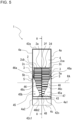
- Fig. 9 is a side view of a centrifugal air-sending device 1 according to Embodiment 3 as seen from a discharge port 42a.
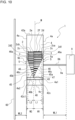
- Fig. 10 is a conceptual diagram of an example of use of the centrifugal air-sending device 1 according to Embodiment 3. Further, components that are identical in configuration to those of the centrifugal air-sending devices 1 in Figs. 1 to 8 are given identical reference signs, and a description of such components is omitted.
- the centrifugal air-sending device 1 according to Embodiment 3 is intended to further specify the configuration of the fan 2 and the extension plate 45.
- the configuration of components other than the fan 2 and the extension plate 45 is similar to that of the centrifugal air-sending device 1 according to Embodiment 1 or 2. The following thus gives a description with reference to Fig. 9 with a focus on the configuration of the fan 2 and the extension plate 45 of the centrifugal air-sending device 1 according to Embodiment 3.
- the plurality of blades 2d of the fan 2 are provided on one surface of the main plate 2a and the other surface of the main plate 2a in the axial direction of the rotation axis RA.
- a plurality of first blades 2d1 provided on the one surface of the main plate 2a and a plurality of second blades 2d2 provided on the other surface of the main plate 2a project from the main plate 2a by different lengths.
- the main plate 2a of the fan 2 is formed such that the main plate 2a is shifted to one side from a center position M of the fan 2 in the axial direction of the rotation axis RA.
- the fan 2 is formed such that the length L1 of each of the plurality of first blades 2d1 is greater than the length L2 of each of the plurality of second blades 2d2.
- the main plate 2a of the fan 2 is located such that the main plate 2a is shifted to the second side plate 2cb from the center position M to be closer to the second side plate 2cb than to the first side plate 2ca.
- the extension plate 45 has the shortest portion 48, which is a portion of the extension plate 45 that is shortest in length in the direction of projection, in which the extension plate 45 projects from the tongue portion 43, when seen from the discharge port 42a, and the shortest portion 48 corresponds in position to the main plate 2a in the axial direction of the rotation axis RA.
- the shortest portion 48 of the extension plate 45 is formed such that the shortest portion 48 is shifted to one side from the center position M of the fan 2 in the axial direction of the rotation axis RA.
- the extension plate 45 is formed such that in the axial direction of the rotation axis RA, the maximum width W1 of the first plate portion 45a is greater than the maximum width W2 of the maximum width W2 of the second plate portion 45b.
- the maximum width W1 of the first plate portion 45a is the width of a section of the extension plate 45 between the first side plate 4a1 and the shortest portion 48 in the basal portion 47
- the maximum width W2 of the second plate portion 45b is the width of a section of the extension plate 45 between the second side plate 4a2 and the shortest portion 48 in the basal portion 47.
- the first plate portion 45a covers the plurality of first blades 2d1 in radial directions of the fan 2, and the second plate portion 45b covers the plurality of second blades 2d2 in radial directions of the fan 2.
- the centrifugal air-sending device 1 is formed such that as shown in Fig. 9 , in a case in which the centrifugal air-sending device 1 is looked into from the discharge port 42a, a portion of the centrifugal air-sending device 1 in which the main plate 2a is located in the axial direction of the rotation axis RA is largest in the width of an opening perpendicular to the rotation axis RA.
- the portion of the centrifugal air-sending device 1 that is largest in the width of the opening perpendicular to the rotation axis RA is formed such that the largest portion is shifted from the center position M of the fan 2 in the axial direction of the rotation axis RA.
- a wall surface portion 60 shown in Fig. 10 is a wall surface of an after-mentioned case 16 of the air-conditioning apparatus 10 or a wall surface of any type of device such as an air-sending device into which the centrifugal air-sending device 1 is incorporated.
- the wall surface portion 60 and a motor 9 are resistance bodies against airflow that flows into the centrifugal air-sending device 1.
- the motor 9 is a resistance body that is located in a position that faces the wall surface portion 60 across the centrifugal air-sending device 1 and that prevents the flow of air.
- the motor 9 is connected to the main plate 2a by use of a motor shaft 9a in between.
- the centrifugal air-sending device 1 is formed such that in the axial direction of the rotation axis RA, the main plate 2a is located such that the main plate 2a is shifted from the center position M of the fan 2 to a side at which the distance between the scroll casing 4 and a resistance body positioned to face one side wall 4a is shorter than the distance between the scroll casing 4 and another resistance body positioned to face the other side wall 4a.
- the centrifugal air-sending device 1 is formed such that in the axial direction of the rotation axis RA, the shortest portion 48 is located such that the shortest portion 48 is shifted from the center position M of the fan 2 to a side at which the distance between the scroll casing 4 and a resistance body positioned to face one side wall 4a is shorter than the distance between the scroll casing 4 and another resistance body positioned to face the other side wall 4a.
- WL1 is the distance between the motor 9 and the other side wall 4a.
- WL2 is the distance between the one side wall 4a of the scroll casing 4 and the wall surface portion 60.
- the centrifugal air-sending device 1 is located such that the main plate 2a and the shortest portion 48 are shifted from the center position M of the fan 2 to the shorter one of the distances WL1 and WL2.
- the centrifugal air-sending device 1 is formed such that the main plate 2a and the shortest portion 48 are located closer to the second side wall 4a2 than is the center position M of the fan 2.
- the centrifugal air-sending device 1 is formed such that the main plate 2a and the shortest portion 48 are located closer to the first side wall 4a1 than is the center position M of the fan 2.
- the centrifugal air-sending device 1 when the distance between the scroll casing 4 and a resistance body positioned to face a side wall 4a is long, the volume of sucked air that flows in through the air inlet 5 is large.
- the centrifugal air-sending device 1 makes it possible to achieve a rise in pressure by increasing the total area of blades 2d in which the volume of sucked air is large, making it possible to increase the volume of discharged air.
- the centrifugal air-sending device 1 when the distance between the scroll casing 4 and a resistance body positioned to face a side wall 4a is long, the volume of discharged air increases and the effect of airflow generated by airflow in the vicinity of the corresponding side plate 2c flowing backward from around the discharge port 42a to the inside of the scroll casing 4 is great.
- the centrifugal air-sending device 1 makes it possible to secure a great width of a portion of the extension plate 45 at which the volume of sucked air is large in the axial direction of the rotation axis RA, making it possible to reduce backflow of the airflow in the vicinity of the corresponding side plate 2c.
- the extension plate 45 has the shortest portion 48, which is a portion of the extension plate 45 that is shortest in length in the direction of projection when seen from the discharge port 42a, and the shortest portion 48 corresponds in position to the main plate 2a in the axial direction of the rotation axis RA. Further, the main plate 2a is formed such that the main plate 2a is shifted to one side from the center position M of the fan 2 in the axial direction of the rotation axis RA.
- the centrifugal air-sending device 1 can bring about effects that are similar to those of Embodiments 1 and 2 or other embodiments by having the main plate 2a and the shortest portion 48 located such that the main plate 2a and the shortest portion 48 are shifted from the center position M to a side at which the volume of sucked air is small.
- the centrifugal air-sending device 1 makes it possible to achieve a rise in pressure by increasing the total area of blades 2d in which the volume of sucked air is large, making it possible to increase the volume of discharged air.
- the centrifugal air-sending device 1 has the fan 2 with the shortest portion 48 shifted to a side at which the distance between one side wall 4a and an airflow resistance body is shorter in the axial direction of the rotation axis RA.
- the centrifugal air-sending device 1 makes it possible to secure a great width of a portion of the extension plate 45 at which the volume of sucked air is large in the axial direction of the rotation axis RA, making it possible to reduce backflow of the airflow in the vicinity of the corresponding side plate 2c.
- the shortest portion 48 of the extension plate 45 corresponds in position to the main plate 2a in the axial direction of the rotation axis RA.
- the variation in length between the other portion closer to the main plate 2a and the one portion closer to the corresponding side plate 2c makes it possible to, without reducing the flow of air in the other portion closer to the main plate 2a, on which the volume of air concentrates, reduce backflow of airflow generated in the one portion closer to the corresponding side plate 2c, making it possible to control a reduction in the volume of air.
- Fig. 11 is a side view of a centrifugal air-sending device 1 according to Embodiment 4 as seen from a discharge port 42a. It should be noted that components that are identical in configuration to those of the centrifugal air-sending devices 1 in Figs. 1 to 10 are given identical reference signs and a description of such components is omitted. Although the centrifugal air-sending device 1 described in any one of Embodiments 1 to 3 is of a double-suction type, the centrifugal air-sending device 1 is not limited to a double-suction centrifugal air-sending device 1 but may be a single-suction centrifugal air-sending device 1.
- the centrifugal air-sending device 1 needs only have at least one side wall 4a in which an air inlet 5 is formed.
- the scroll casing 4 of the centrifugal air-sending device 1 has a side wall 4a covering the fan 2 in the axial direction of the rotation axis RA of the fan 2 and having the air inlet 5 formed in the side wall 4a and through which air is taken in and a peripheral wall 4c surrounding the fan 2 in radial directions that start from the rotation axis RA as a radial center.
- the scroll casing 4 of the single-suction centrifugal air-sending device 1 has a side wall 4a3 perpendicular to the axial direction of the rotation axis RA.
- the scroll casing 4 of Embodiment 4 is a single-suction casing in which the air inlet 5 is formed only at one side of the fan 2 in the axial direction of the rotation axis RA.
- the centrifugal air-sending device 1 of Embodiment 4 includes one side wall 4a in which the air inlet 5 is formed and includes one side wall 4a in which no air inlet 5 is formed.
- the plurality of blades 2d of the centrifugal air-sending device 1 are provided on one side of the main plate 2a in the axial direction of the rotation axis RA.
- the main plate 2a of the fan 2 is located closer to the side wall 4a3 than is the side plate 2c, and the side plate 2c of the fan 2 is located closer to the first side wall 4a1 than is the main plate 2a.
- the extension plate 45 of Embodiment 4 is formed in a right triangular shape when seen from the discharge port 42a.
- the extension plate 45 has a notch 46b cut diagonally when seen from the discharge port 42a.
- the distal end portion 46 of the extension plate 45 forms an edge 46c of the extension plate 45, and the edge 46c of the extension plate 45 forms the diagonal notch 46b.
- the edge 46c of the extension plate 45 is formed in a diagonal shape.
- an edge portion of the extension plate 45 that is formed by the distal end portion 46 may be formed in a linear shape between the one portion closer to the side plate 2c and the other portion closer to the main plate 2a.
- an edge portion of the extension plate 45 that is formed by the distal end portion 46 may be formed in a wave shape between the one portion closer to the side plate 2c and the other portion closer to the main plate 2a.
- the length of the extension plate 45, which projects from the tongue portion 43 is longest in one portion closest to the side plate 2c and shortest in another portion closest to the main plate 2a.
- the length of the extension plate 45, which projects from the tongue portion 43 is longest in one portion of the extension plate 45 that is closest to the first side wall 4a1, in which the air inlet 5 is formed, and shortest in another portion of the extension plate 45 that is closest to the side wall 4a3, in which no air inlet 5 is formed.
- the extension plate 45 has the shortest portion 48, which is a portion of the extension plate 45 that is shortest in length in the direction of projection, in which the extension plate 45 projects from the tongue portion 43, when seen from the discharge port 42a, and the shortest portion 48 corresponds in position to the main plate 2a in the axial direction of the rotation axis RA.
- the centrifugal air-sending device 1 is formed such that as shown in Fig. 11 , in a case in which the centrifugal air-sending device 1 is looked into from the discharge port 42a, a portion of the centrifugal air-sending device 1 in which the main plate 2a is located in the axial direction of the rotation axis RA is largest in the width of an opening perpendicular to the rotation axis RA.
- the scroll casing 4 of Embodiment 4 is a single-suction casing in which the air inlet 5 is formed only at one side of the fan 2 in the axial direction of the rotation axis RA.
- the centrifugal air-sending device 1 of Embodiment 4 is a single-suction centrifugal air-sending device 1 having one side wall 4a in which the air inlet 5 is formed and having one-sided configuration in which air is sucked into the scroll casing 4.
- the single-suction centrifugal air-sending device 1 too has the tongue-portion-side end 42c1 and the extension plate 45 of which length of extension from the tongue portion 43 increases from the other portion closer to the main plate 2a toward the one portion closer to the side plate 2c.
- the extension plate 45 reduces backflow of airflow from around the discharge port 42a toward the inside of the scroll casing 4, and the formation of the extension plate 45 in the shape of a plate makes it possible to ensure a rise in pressure inside the scroll casing 4.
- the tongue-portion-side end 42c1 is located opposite to the extreme distal end 46a in the circumferential direction CD across the reference line RL. This makes it possible to ensure the opening area of the discharge port 42a and control a reduction in the volume of air that is discharged.
- the single-suction centrifugal air-sending device 1 too makes it possible to bring about effects that are similar to those of the centrifugal air-sending device 1 any one of Embodiments 1 to 3 by having the tongue-portion-side end 42c1 and the extension plate 45.
- Fig. 12 is a perspective view of an air-conditioning apparatus 10 according to Embodiment 5.
- Fig. 13 is a schematic view showing an internal configuration of the air-conditioning apparatus 10 according to Embodiment 5.
- a centrifugal air-sending device 1 which is used in the air-conditioning apparatus 10 according to Embodiment 5
- components that are identical in configuration to those of the centrifugal air-sending device 1 or other devices in Figs. 1 to 11 are given identical reference signs, and a description of such components is omitted.
- Fig. 13 omits an upper surface portion 16a to show the internal configuration of the air-conditioning apparatus 10.
- the air-conditioning apparatus 10 includes the centrifugal air-sending devices 1 and a heat exchanger 20 through which air caused by the centrifugal air-sending devices 1 to flow passes. It should be noted that the air-conditioning apparatus 10 may include multiple centrifugal air-sending devices 1 instead of including a single centrifugal air-sending device 1. Further, the air-conditioning apparatus 10 according to Embodiment 5 includes a case 16 in which the centrifugal air-sending devices 1 and the heat exchanger 20 are housed.
- the case 16 is formed in a cuboidal shape including the upper surface portion 16a, a lower surface portion 16b, and side surface portions 16c.
- the shape of the case 16 is not limited to the cuboidal shape but may for example be another shape such as a circular columnar shape, a prismatic shape, a conical shape, a shape having a plurality of corner portions, and a shape having a plurality of curved surface portions.
- One of the side surface portions 16c of the case 16 is one side surface portion 16c having a case discharge port 17 formed in the one side surface portion 16c.
- Another one of the side surface portions 16c of the case 16 is another side surface portion 16c having a case suction port 18 formed in the other side surface portion 16c and being opposite to the side surface portion 16c having the case discharge port 17 formed in the one side surface portion 16c.
- a filter that removes dust in the air may be disposed at the case suction port 18.
- the case discharge port 17 and the case suction port 18 are not limited to being formed in the side surface portions 16c but may be formed in the lower surface portion 16b and the upper surface portion 16a.
- the centrifugal air-sending devices 1 each include the fan 2, the scroll casing 4 having the bell mouth 3 formed in the scroll casing 4, and the motor 9.
- the motor 9 is supported by a motor support 9b fixed to the upper surface portion 16a of the case 16.
- the motor 9 has the motor shaft 9a.
- the air-conditioning apparatus 10 has two fans 2 attached to the motor shaft 9a.
- the fans 2 of the centrifugal air-sending devices 1 form a flow of air that is sucked into the case 16 through the case suction port 18 and blown out into an air-conditioned space through the case discharge port 17.
- the number of fans 2, which are disposed in the case 16, is not limited to two but may be one or larger than or equal to three.
- the centrifugal air-sending devices 1 are attached to a partition plate 19 that partitions an internal space of the case 16 into a space S11 facing a suction side of the scroll casings 4 and a space S12 facing a blowout side of the scroll casings 4.
- the heat exchanger 20 is located in a position that faces the discharge ports 42a of the centrifugal air-sending devices 1, and is disposed in the case 16 to be on an air trunk of air to be discharged by the centrifugal air-sending devices 1.
- the heat exchanger 20 adjusts the temperature and the humidity of air that is sucked into the case 16 through the case suction port 18 and blown out into the air-conditioned space through the case discharge port 17.
- Rotation of the fans 2 of the centrifugal air-sending devices 1 causes the air in the air-conditioned space to be sucked into the case 16 through the case suction port 18.
- the air sucked into the case 16 is guided to the bell mouths 3 and sucked into the fans 2.
- the air sucked into the fans 2 is blown out outward in radial directions of the respective fans 2.
- the air blown out from the fans 2 passes through the inside of the scroll casings 4, is blown out from the scroll casings 4 through the discharge ports 42a, and then is supplied to the heat exchanger 20.
- the air supplied to the heat exchanger 20 is subjected to temperature and humidity control by, during passage through the heat exchanger 20, exchanging heat with refrigerant flowing through the inside of the heat exchanger 20.
- the air having passed through the heat exchanger 20 is blown out to the air-conditioned space through the case discharge port 17.
- the air-conditioning apparatus 10 according to Embodiment 5 includes the centrifugal air-sending device 1 according to any one of Embodiments 1 to 4. Therefore, the air-conditioning apparatus 10 can bring about effects that are similar to those of the centrifugal air-sending device 1 according to any one of Embodiments 1 to 4.
- centrifugal air-sending device 2: fan, 2a: main plate, 2a1: periphery, 2b: boss portion, 2c: side plate, 2ca: first side plate, 2cb: second side plate, 2d: blade, 2d1: blade, 2d2: blade, 2e: fan air inlet, 2f: outer circumferential face, 2g: outer periphery, 2h: apex, 3: bell mouth, 4: scroll casing, 4a: side wall, 4a1: first side wall, 4a2: second side wall, 4a3: side wall, 4c: peripheral wall, 5: air inlet, 5a: first air inlet, 5b: second air inlet, 9: motor, 9a: motor shaft, 9b: motor support, 10: air-conditioning apparatus, 12: turbo blade portion, 13: sirocco blade portion, 14: inner circumferential end, 15: outer circumferential end, 16: case, 16a: upper surface portion, 16b: lower surface portion, 16c: side surface portion
Landscapes
- Engineering & Computer Science (AREA)
- Mechanical Engineering (AREA)
- General Engineering & Computer Science (AREA)
- Chemical & Material Sciences (AREA)
- Combustion & Propulsion (AREA)
- Structures Of Non-Positive Displacement Pumps (AREA)
Abstract
Description
- The present disclosure relates to a centrifugal air-sending device having a scroll casing and to an air-conditioning apparatus.
- An existing centrifugal air-sending device includes a fan having a main plate that is disc-shaped, a plurality of blades located around a periphery of the main plate, and a side plate that is located such that the side plate faces the main plate, and fixes the blades. Further, to raise the pressure of airflow generated by the rotation of the fan and flowing out from the blades, the existing centrifugal air-sending device includes a scroll casing that is spiral-shaped, has a tongue portion from which an air trunk starts to be gradually expanded, and guides the airflow to a discharge port. In the existing centrifugal air-sending device, the air trunk is abruptly expanded in the vicinity of the discharge port, there is a difference in direction of the airflow between one portion of the fan that is closer to the main plate than is another portion of the fan that is closer to the side plate than is the one portion and the other portion. Therefore, in the existing centrifugal air-sending device, a portion of the airflow that flows through the other portion closer to the side plate does not flow toward the discharge port but flows backward into the scroll casing while sucking in air from around the discharge port. This may reduce the volume of air and increase noise. To address this problem, there has been proposed a centrifugal air-sending device in which as seen in a direction of a rotation axis of the fan, the tongue portion is located such that the tongue portion sequentially stretched in a direction of rotation of the fan as the tongue portion extends from the one portion closer to the main plate toward the other portion closer to the side plate, whereby backflow of the airflow in the other portion closer to the side plate is reduced and a reduction in the volume of air and an increase in noise are controlled (see, for example, Patent Literature 1).
- Patent Literature 1:
Japanese Unexamined Patent Application Publication No. 2020-029838 - However, when the centrifugal air-sending device of
Patent Literature 1 is installed in a narrow space, the distance from the tongue portion to a discharge-port end cannot be lengthened. Therefore, in a state in which the wall thickness of the tongue portion is great as in the case of the centrifugal air-sending device ofPatent Literature 1, the centrifugal air-sending device may not be able to raise pressure inside the scroll casing, as the air trunk cannot be sufficiently expanded, and may reduce the volume of air that is discharged, as the discharge port has a narrow opening. - The present disclosure is made to solve the above problems and has as an object to provide a centrifugal air-sending device and an air-conditioning apparatus that, even when installed in a narrow space, can raise pressure inside a scroll casing while preventing backflow of airflow in the scroll casing and control a reduction in the volume of air that is discharged.
- A centrifugal air-sending device according to an embodiment of the present disclosure includes a fan and a scroll casing. The fan has a main plate that is disc-shaped, a plurality of blades located around a periphery of the main plate, and a side plate that is ring-shaped, is located such that the side plate faces the main plate, and fixes ends of the plurality of blades that are opposite to the main plate. The scroll casing has a peripheral wall that is spiral-shaped and at least one side wall that has a bell mouth that forms an air inlet that communicates with a space surrounded by the main plate and the plurality of blades. The scroll casing forms a discharge port through which airflow generated by the fan is discharged. The scroll casing houses the fan. The scroll casing has a tongue portion and an extension plate. The tongue portion forms a curved surface at a winding-start portion of the peripheral wall that is closer to a rotation axis of the fan than are other portions of the peripheral wall. The tongue portion guides the airflow generated by the fan to the discharge port. The extension plate is plate-shaped, projects from the tongue portion, is spaced apart from the fan, and extends from the tongue portion along an outer periphery of the fan. The extension plate has one portion that is closer to the side plate than is another portion of the extension plate that is closer to the main plate than is the one portion. The one portion is formed longer than the other portion in a circumferential direction of the fan. The extension plate has a distal end portion that extends in a direction of projection in which the extension plate projects from the tongue portion. The distal end portion has an extreme distal end that is located at a boundary between the distal end portion and the at least one side wall. The scroll casing has, in a case in which the scroll casing is projected in an axial direction of the rotation axis, a tongue-portion-side end that is located in a discharge-port edge that is a portion that corresponds to the discharge port. The tongue-portion-side end is an end that is closer to the tongue portion than is another end of the discharge-port edge. The tongue-portion-side end is located opposite to the extreme distal end in the circumferential direction across a reference line drawn perpendicular to the discharge-port edge from the rotation axis.
- An air-conditioning apparatus according to an embodiment of the present disclosure includes the centrifugal air-sending device described above and a heat exchanger through which air caused by the centrifugal air-sending device to flow passes.
- The centrifugal air-sending device according to an embodiment of the present disclosure has an extension plate that is plate-shaped, projects from the tongue portion, is spaced apart from the fan, and extends from the tongue portion along an outer periphery of the fan. The extension plate has one portion that is closer to the side plate than is another portion of the extension plate that is closer to the main plate than is the one portion. The one portion is formed longer than the other portion in a circumferential direction of the fan. In the centrifugal air-sending device, the one portion of the extension plate reduces backflow of the airflow from around the discharge port toward the inside of the scroll casing, whereby the airflow can be smoothly guided from the one portion to the discharge port. Further, in the centrifugal air-sending device, the formation of the extension plate in the shape of a plate makes it possible to ensure the distance between the extension plate and the discharge port and sufficiently ensure an air trunk, thus making it possible to surely raise pressure inside the scroll casing. Furthermore, in the centrifugal air-sending device, the extension plate has a distal end portion that extends in a direction of projection in which the extension plate projects from the tongue portion. The distal end portion has an extreme distal end that is located at a boundary between the distal end portion and the at least one side wall. The tongue-portion-side end is located opposite to the extreme distal end in the circumferential direction across a reference line drawn perpendicular to the discharge-port edge from the rotation axis. Therefore, the centrifugal air-sending device can ensure the opening area of the discharge port and control a reduction in the volume of air that is discharged.
-
- [
Fig. 1] Fig. 1 is a perspective view of a centrifugal air-sending device according toEmbodiment 1. - [
Fig. 2] Fig. 2 is a side view of the centrifugal air-sending device inFig. 1 as seen from a discharge port. - [
Fig. 3] Fig. 3 is a schematic view of the centrifugal air-sending device according toEmbodiment 1 as seen in an axial direction of a rotation axis at a position in the centrifugal air-sending device indicated by line A-A inFig. 2 . - [
Fig. 4] Fig. 4 is a side view of a first modification of the centrifugal air-sending device ofEmbodiment 1 as seen from a discharge port. - [
Fig. 5] Fig. 5 is a side view of a second modification of the centrifugal air-sending device ofEmbodiment 1 as seen from a discharge port. - [
Fig. 6] Fig. 6 is a schematic view of a centrifugal air-sending device according to a comparative example as seen in an axial direction of a rotation axis. - [
Fig. 7] Fig. 7 is a side view of the centrifugal air-sending device inFig. 6 as seen from a discharge port. - [
Fig. 8] Fig. 8 is a schematic view of a centrifugal air-sending device according toEmbodiment 2 as seen in an axial direction of a rotation axis at a position in the centrifugal air-sending device indicated by line A-A inFig. 2 . - [
Fig. 9] Fig. 9 is a side view of a centrifugal air-sending device according toEmbodiment 3 as seen from a discharge port. - [
Fig. 10] Fig. 10 is a conceptual diagram of an example of use of the centrifugal air-sending device according toEmbodiment 3. - [
Fig. 11] Fig. 11 is a side view of a centrifugal air-sending device according to Embodiment 4 as seen from a discharge port. - [
Fig. 12] Fig. 12 is a perspective view of an air-conditioning apparatus according to Embodiment 5. - [
Fig. 13] Fig. 13 is a schematic view showing an internal configuration of the air-conditioning apparatus according toEmbodiment 5. - In the following, a centrifugal air-sending device and an air-conditioning apparatus according to embodiments are described, for example, with reference to the drawings. In the following drawings including
Fig. 1 , relative relationships in dimension between constituent elements, the shapes of the constituent elements, or other features of the constituent elements may be different from actual ones. Further, constituent elements given identical reference signs in the following drawings are identical or equivalent to each other, and these reference signs are common throughout the full text of the specification. Further, the directive terms (such as "upper", "lower", "right", "left", "front", and "back") used as appropriate for ease of comprehension are merely so written for convenience of explanation, and are not intended to limit the placement or orientation of a device or a component. -
Fig. 1 is a perspective view of a centrifugal air-sendingdevice 1 according toEmbodiment 1.Fig. 2 is a side view of the centrifugal air-sendingdevice 1 inFig. 1 as seen from adischarge port 42a.Fig. 3 is a schematic view of the centrifugal air-sendingdevice 1 according toEmbodiment 1 as seen in an axial direction of a rotation axis RA at a position in the centrifugal air-sendingdevice 1 indicated by line A-A inFig. 2 . It should be noted thatFig. 3 is also a conceptual diagram in which ascroll casing 4 of the centrifugal air-sendingdevice 1 ofEmbodiment 1 is projected in the axial direction of the rotation axis RA. A circumferential direction CD indicated by arrows inFigs. 1 and3 indicates a circumferential direction of afan 2. A basic structure of the centrifugal air-sendingdevice 1 is described with reference toFigs. 1 to 3 . - The centrifugal air-sending
device 1 is a multi-blade centrifugal air-sending device, and includes afan 2, which generates airflow, and ascroll casing 4 in which thefan 2 is housed. The centrifugal air-sendingdevice 1 is a double-suction centrifugal air-sending device into which air is sucked through both ends of thescroll casing 4 in an axial direction of the rotation axis RA of thefan 2, which is virtually drawn. - The
fan 2 is a centrifugal fan. Thefan 2 is connected to a motor (not illustrated) having a drive shaft. Thefan 2 is driven into rotation by the motor. The rotation generates a centrifugal force with which thefan 2 forcibly sends out air outward in radial directions. Thefan 2 is rotated, for example, by the motor in a direction of rotation R indicated by an arrow. - As shown in
Fig. 1 , thefan 2 has amain plate 2a, which is disc-shaped, aside plate 2c, which is ring-shaped, and a plurality ofblades 2d arranged around a periphery 2a1 of themain plate 2a in a radial manner around the rotation axis RA. Thefan 2 is formed in the shape of a circular cylinder by the plurality ofblades 2d arranged on themain plate 2a. Thefan 2 has afan air inlet 2e formed in a portion of thefan 2 that is opposite to themain plate 2a and closer to theside plate 2c than are other portions of thefan 2 in the axial direction of the rotation axis RA. Thefan air inlet 2e allows gas to flow into a space surrounded by themain plate 2a and the plurality ofblades 2d. - The
main plate 2a needs only be in the shape of a plate, and may for example have a non-disc shape such as a polygonal shape. Further, themain plate 2a may be formed such that the thickness of themain plate 2a increases toward the center in a radial directions that start from the rotation axis RA as a radial center, or may be formed such that the thickness is uniform in radial directions that start from the rotation axis RA as a radial center. Further, instead of being formed by one plate-shaped element, themain plate 2a may be formed by a plurality of plate-shaped elements integrally fixed to each other. It should be noted that the radial directions that start from the rotation axis RA as a radial center are each a direction perpendicular to the axial direction of the rotation axis RA. - At a central part of the
main plate 2a, aboss portion 2b to which the drive shaft of the motor is connected is provided. Theboss portion 2b has a shaft hole into which the drive shaft of the motor is inserted. Although theboss portion 2b is formed in a circular columnar shape, the shape of theboss portion 2b is not limited to the circular columnar shape. Theboss portion 2b needs only be formed in a columnar shape, and may for example be formed in a polygonal columnar shape. Themain plate 2a is driven into rotation by the motor by use of theboss portion 2b in between. - The
fan 2 has theside plate 2c, which is ring-shaped and is attached to ends of the plurality ofblades 2d that are opposite to themain plate 2a in the axial direction of the rotation axis RA. Theside plate 2c fixes the ends of the plurality ofblades 2d that are opposite to themain plate 2a. Theside plate 2c is provided at an outercircumferential face 2f of thefan 2, and in thefan 2, is located such that theside plate 2c faces themain plate 2a. Theside plate 2c is provided at outer portions of theblades 2d in radial directions that start from the rotation axis RA as a radial center. Theside plate 2c may be provided at distal end portions of the plurality ofblades 2d that project from themain plate 2a in a direction of the rotation axis RA. Theside plate 2c joins the plurality ofblades 2d with each other, thereby maintaining a positional relationship between the distal end of eachblade 2d and the distal end of theother blade 2d and reinforcing the plurality ofblades 2d. - The
side plate 2c includes a first side plate 2ca, which is ring-shaped and is located such that the first side plate 2ca faces themain plate 2a, and a second side plate 2cb, which is ring-shaped and is located such that the second side plate 2cb faces themain plate 2a and is located opposite to the first side plate 2ca across themain plate 2a. It should be noted that the term "side plate 2c" is a generic name for the first side plate 2ca and the second side plate 2cb, and thefan 2 has the first side plate 2ca at one side of themain plate 2a in the axial direction of the rotation axis RA and has the second side plate 2cb at the other side. Although, inFig. 2 , the first side plate 2ca is located at the right side of themain plate 2a and the second side plate 2cb is located at the left side of themain plate 2a, the first side plate 2ca and the second side plate 2cb may swap their positions with each other. - The plurality of
blades 2d are arranged in the circumferential direction CD centered around the rotation axis RA. One end of each of the plurality ofblades 2d is connected to themain plate 2a, and the other end of each of the plurality ofblades 2d is connected to theside plate 2c. Each of the plurality ofblades 2d is located at least between themain plate 2a and theside plate 2c. The plurality ofblades 2d are arranged in a circumferential manner centered around theboss portion 2b and have their proximal ends fixed on surfaces of themain plate 2a. - The plurality of
blades 2d are provided on one surface of themain plate 2a and the other surface of themain plate 2a in the axial direction of the rotation axis RA. The plurality ofblades 2d are provided on both sides of themain plate 2a in the axial direction of the rotation axis RA. - The
blades 2d are placed at regular spacings from each other in the circumferential direction CD around the periphery 2a1 of themain plate 2a. Theblades 2d are provided such that theblades 2d rise from themain plate 2a and are each formed in the shape of a plate. Although theblades 2d are provided such that theblades 2d rise substantially perpendicular to themain plate 2a, this is not intended to impose any limitation. Alternatively, theblades 2d may be provided at an angle to a direction perpendicular to themain plate 2a. - The
fan 2 is driven into rotation around the rotation axis RA by driving of the motor (not illustrated). The rotation of thefan 2 causes gas outside the centrifugal air-sendingdevice 1 to be sucked into the space surrounded by themain plate 2a and the plurality ofblades 2d through anair inlet 5 formed in thescroll casing 4 and thefan air inlet 2e of thefan 2, which are shown inFig. 1 . Moreover, the rotation of thefan 2 causes air sucked into the space surrounded by themain plate 2a and the plurality ofblades 2d to be sent out outward in radial directions of thefan 2 through a space between ablade 2d and anadjacent blade 2d. - The
scroll casing 4 houses thefan 2 inside and rectifies a flow of air blown out from thefan 2. Thescroll casing 4 is a double-suction casing havingside walls 4a at both respective sides of themain plate 2a in the axial direction of the rotation axis RA with the after-mentionedair inlets 5 formed in theside walls 4a. Thescroll casing 4 has ascroll portion 41 and adischarge portion 42. Thescroll casing 4 has aperipheral wall 4c, which is spiral-shaped, and at least oneside wall 4a, which has abell mouth 3, which forms anair inlet 5, which communicates with a space surrounded by themain plate 2a and the plurality ofblades 2d. - The
scroll portion 41 has an air trunk through which a dynamic pressure of the airflow generated by thefan 2 is converted into a static pressure. Thescroll portion 41 has aside wall 4a covering thefan 2 in the axial direction of the rotation axis RA and aperipheral wall 4c surrounding thefan 2 in radial directions that start from the rotation axis RA, as a radial center, of theboss portion 2b. - Further, the
scroll portion 41 has atongue portion 43, which is located between thescroll portion 41 and thedischarge portion 42, forms a curved surface, and guides the airflow generated by thefan 2 to thedischarge port 42a via thescroll portion 41. Thescroll portion 41 has an internal space that is defined by theperipheral wall 4c and theside wall 4a and that allows air blown out from thefan 2 to flow along theperipheral wall 4c. - The
scroll casing 4 has at least oneside wall 4a, which has abell mouth 3, which forms anair inlet 5. InEmbodiment 1, the at least oneside wall 4a of thescroll casing 4 includes twoside walls 4a. Theseside walls 4a ofEmbodiment 1 are located at both respective sides of thefan 2 in the axial direction of the rotation axis RA. The twoside walls 4a located at both respective sides of thefan 2 are formed to face each other across theperipheral wall 4c. As shown inFig. 2 , thescroll casing 4 ofEmbodiment 1 includes a first side wall 4a1 and a second side wall 4a2 as theside walls 4a. - The first side wall 4a1 is a
side wall 4a that is located at a side that is opposite to themain plate 2a and at which the first side plate 2ca is located. The second side wall 4a2 is aside wall 4a that is located at a side that is opposite to themain plate 2a and at which the second side plate 2cb is located. The term "side wall 4a" is a generic name for the first side wall 4a1 and the second side wall 4a2. - The
side wall 4a of thescroll casing 4 has anair inlet 5 formed in theside wall 4a such that that air can flow between thefan 2 and the outside of thescroll casing 4.
Theair inlet 5 is an air inlet that communicates with thefan air inlet 2e and allows gas to flow into the space surrounded by themain plate 2a and the plurality ofblades 2d. - At the first side wall 4a1, a
first air inlet 5a is formed. Thefirst air inlet 5a is formed in a position that faces a plate side of themain plate 2a at which the first side plate 2ca is located. At the second side wall 4a2, asecond air inlet 5b is formed. Thesecond air inlet 5b is formed in a position that faces a plate side of themain plate 2a at which the second side plate 2cb is located. The aforementioned term "air inlet 5" is a generic name for thefirst air inlet 5a and thesecond air inlet 5b. - The
air inlet 5 provided in theside wall 4a is formed by thebell mouth 3. Theair inlet 5 formed by thebell mouth 3 allows a space outside thescroll casing 4 and the space surrounded by themain plate 2a and the plurality ofblades 2d to communicate with each other. Thebell mouth 3 allows gas that is to be sucked into thefan 2 to be rectified and flow into thefan 2 through thefan air inlet 2e. - The
bell mouth 3 has an opening of which diameter gradually decreases from the outside toward the inside of thescroll casing 4. Such a configuration of theside wall 4a allows air in the vicinity of theair inlet 5 to smoothly flow along thebell mouth 3 and efficiently flow into thefan 2 through theair inlet 5. - The
peripheral wall 4c is a wall that guides the airflow generated by thefan 2 to thedischarge port 42a along a curved wall surface. Theperipheral wall 4c is formed in a spiral shape. Theperipheral wall 4c is formed such that the distance of theperipheral wall 4c from the rotation axis RA gradually increases as theperipheral wall 4c extends in the direction of rotation R of thefan 2. Theperipheral wall 4c is formed such that in the direction of rotation R of thefan 2, a gap between theperipheral wall 4c and the outer circumference of thefan 2 increases at a predetermined rate from thetongue portion 43 to thedischarge portion 42 and the flow passage area of air gradually increases. - An example of the spiral shape of the
peripheral wall 4c is a shape such as a logarithmic spiral, a spiral of Archimedes, and an involute curve. The inner circumferential surface of theperipheral wall 4c forms a curved surface smoothly curved along a circumferential direction of thefan 2 from thetongue portion 43, from which theperipheral wall 4c extends to be formed in the spiral shape, to a winding-end portion 41b until which theperipheral wall 4c extends to be formed in the spiral shape. Such a configuration allows air sent out from thefan 2 to smoothly flow through the gap between thefan 2 and theperipheral wall 4c toward thedischarge portion 42 in the direction of an arrow F1 shown inFig. 3 . This effects an efficient rise in static pressure of air from thetongue portion 43 toward thedischarge portion 42 in thescroll casing 4. - The
peripheral wall 4c is a wall provided between theside walls 4a, which face each other, and forms a curved surface extending along the direction of rotation R of thefan 2. Theperipheral wall 4c is for example located parallel to the axial direction of the rotation axis RA and covers thefan 2. It should be noted that theperipheral wall 4c may be formed at an angle to an axial direction of the rotation axis RA of thefan 2, and is not limited to being located parallel to the axial direction of the rotation axis RA. - The
peripheral wall 4c forms an inner wall surface that faces the outercircumferential face 2f of thefan 2. Theperipheral wall 4c faces outer circumferential ends of the plurality ofblades 2d that form the outercircumferential face 2f of thefan 2. Theperipheral wall 4c faces ends of theblades 2d through which air is blown out from thefan 2. As shown inFig. 3 , theperipheral wall 4c is provided over an area from thetongue portion 43, from which theperipheral wall 4c extends to be formed in the spiral shape, to the winding-end portion 41b, which is located at a boundary between thedischarge portion 42 and thescroll portion 41 that are away from thetongue portion 43, along the direction of rotation R of thefan 2. - The
tongue portion 43 is an end of theperipheral wall 4c that forms a curved surface upstream in a direction of flow of gas allowed by rotation of thefan 2 to flow along theperipheral wall 4c through an internal space of thescroll casing 4. The winding-end portion 41b is an end of theperipheral wall 4c that forms a curved surface downstream in the direction of flow of gas allowed by the rotation of thefan 2 to flow along theperipheral wall 4c through the internal space of thescroll casing 4. - The
scroll casing 4 has atongue portion 43, which forms a curved surface at a winding-start portion of theperipheral wall 4c that is closer to the rotation axis RA of thefan 2 than are other portions of theperipheral wall 4c, and thetongue portion 43 guides the airflow generated by thefan 2 to thedischarge port 42a. Theperipheral wall 4c includes thetongue portion 43 at an end of theperipheral wall 4c that is closer to thedischarge portion 42 than is the other end of theperipheral wall 4c. Thetongue portion 43 is formed at the winding-start portion of theperipheral wall 4c, which is spiral-shaped. - The
tongue portion 43 is located at a boundary with adiffuser plate 42c of the after-mentioneddischarge portion 42. Thetongue portion 43 is formed to have a curved surface and is formed in the shape of an arc when seen in the axial direction of the rotation axis RA. Thetongue portion 43 is formed with a predetermined radius of curvature, and theperipheral wall 4c is smoothly connected to thediffuser plate 42c with thetongue portion 43 in between. Thetongue portion 43 is in substantially the same shape in the axial direction of the rotation axis RA when seen from thedischarge port 42a and is shaped along the axial direction of the rotation axis RA. - The
tongue portion 43 reduces inflow of air from the winding start to the winding end of a scroll flow passage. Thetongue portion 43 is located in an upstream part of a ventilation flue, and has a role to effect diversion into a flow of air in the direction of rotation R of thefan 2 and a flow of air in a discharge direction from a downstream part of the ventilation flue toward thedischarge port 42a. Further, a flow of air flowing into thedischarge portion 42 rises in static pressure during passage through thescroll casing 4 to be high in pressure. Therefore, thetongue portion 43 has a function of separating such different pressures. - As shown in
Figs. 2 to 3 , thescroll casing 4 has anextension plate 45, which is plate-shaped, projects from thetongue portion 43, is spaced apart from thefan 2 at a spacing SP, and extends from thetongue portion 43 alongouter peripheries 2g of thefan 2. Theextension plate 45 is formed to project from thetongue portion 43 in a direction of reverse rotation of thefan 2. The direction of reverse rotation of thefan 2 is a direction opposite to the direction of rotation R of thefan 2. Theextension plate 45 extends from thetongue portion 43 along theouter peripheries 2g of thefan 2 in the circumferential direction CD and extends in the axial direction of the rotation axis RA. - As shown in
Fig. 2 , theextension plate 45 has one portion that is closer to each of theside plates 2c than is another portion of theextension plate 45 that is closer to themain plate 2a than is the one portion, and the one portion is formed longer than the other portion in the circumferential direction CD (seeFig. 1 ) of thefan 2. In the circumferential direction CD (seeFig. 3 ) of thefan 2, the length of theextension plate 45, which projects from thetongue portion 43, is longest in the one portion and shortest in the other portion. That is, theextension plate 45 has one portion that is closer to each of theside plates 2c than is another portion of theextension plate 45 that is closer to themain plate 2a than is the one portion in the axial direction of the rotation axis RA, and the one portion is formed longer than the other portion in the circumferential direction CD. It should be noted that the one portion closer to thecorresponding side plate 2c and the other portion closer to themain plate 2a indicate a relative positional relationship between the position of theextension plate 45 and other positions in the axial direction of the rotation axis RA. - As shown in
Fig. 3 , thescroll casing 4 has, in a case in which thescroll casing 4 is projected in an axial direction of the rotation axis RA, a tongue-portion-side end 42c1 located in a discharge-port edge 42a1, which is a portion that corresponds to thedischarge port 42a, and the tongue-portion-side end 42c1 is an end that is closer to thetongue portion 43 than is the other end of the discharge-port edge 42a1. Further, as shown inFig. 3 , thescroll casing 4 has, in a case in which thescroll casing 4 is projected in an axial direction of the rotation axis RA, a far end 42c2 located in a discharge-port edge 42a1, which is a portion that corresponds to thedischarge port 42a, and the far end 42c2 is an end that is opposite to tongue-portion-side end 42c1. The tongue-portion-side end 42c1 is a first end, and the far end 42c2 is a second end. - As shown in
Fig. 3 , the tongue-portion-side end 42c1 is located opposite to an extremedistal end 46a in the circumferential direction CD across a reference line RL drawn perpendicular to the discharge-port edge 42a1 from the rotation axis RA. As shown inFig. 2 , the extreme distal ends 46a are respective portions ofdistal end portions 46 that extend in a direction of projection in which theextension plate 45 projects from thetongue portion 43, and are each located at a boundary between a correspondingdistal end portion 46 and thecorresponding side wall 4a. - As shown in
Fig. 2 , the part of thefan 2 that is farthest away from the rotation axis RA in a radial direction of thefan 2 in a case in which thescroll casing 4 is looked into from thedischarge port 42a is an apex 2h. As shown inFig. 2 , theextension plate 45 is formed such that the extreme distal ends 46a are located between thetongue portion 43 and the apex 2h in a case in which thescroll casing 4 is looked into from thedischarge port 42a. - The
extension plate 45 includes abasal portion 47, which serves as a boundary between theextension plate 45 and thetongue portion 43. Theextension plate 45 is formed such that the thickness of a plate that forms theextension plate 45 from thebasal portion 47, which serves as a boundary between theextension plate 45 and thetongue portion 43, to the extremedistal ends 46a is a uniform thickness that falls within a predetermined range. Theextension plate 45 is formed such that the thickness of a plate that forms theextension plate 45 is equal to the thickness of a plate that forms theperipheral wall 4c. Although the thickness of theextension plate 45 is less than or equal to 2 mm in a case in which theextension plate 45 is made from a steel plate and less than or equal to 4 mm in a case in which theextension plate 45 is made from resin, the thickness of theextension plate 45 is not limited to these thicknesses. - As shown in
Fig. 2 , theextension plate 45 ofEmbodiment 1 includes afirst plate portion 45a and asecond plate portion 45b, which are formed in right triangular shapes when seen from thedischarge port 42a. Theextension plate 45 is formed such that an oblique side of thefirst plate portion 45a and an oblique side of thesecond plate portion 45b face each other in the axial direction of the rotation axis RA. - The
extension plate 45 has anotch 46b cut in a V shape when seen from thedischarge port 42a. Air of which pressure is raised in thescroll casing 4 and that flows toward thedischarge port 42a passes through thenotch 46b and is discharged out from thescroll casing 4 through thedischarge port 42a. Thedistal end portions 46 of theextension plate 45 each form anedge 46c of theextension plate 45, and theedges 46c of theextension plate 45 form the V-shapednotch 46b. Theedges 46c of theextension plate 45 are formed in a V shape. As with theedges 46c shown inFig. 2 , an edge portion of theextension plate 45 that is formed by each of thedistal end portions 46 is formed in a linear shape between the one portion closer to thecorresponding side plate 2c and the other portion closer to themain plate 2a. - As shown in
Fig. 2 , theextension plate 45 has ashortest portion 48, which is a portion of theextension plate 45 that is shortest in length in the direction of projection, in which theextension plate 45 projects from thetongue portion 43, when seen from thedischarge port 42a, and theshortest portion 48 corresponds in position to themain plate 2a in the axial direction of the rotation axis RA. - By having the
extension plate 45, the centrifugal air-sendingdevice 1 is formed such that as shown inFig. 2 , in a case in which the centrifugal air-sendingdevice 1 is looked into from thedischarge port 42a, a portion of the centrifugal air-sendingdevice 1 in which themain plate 2a is located in the axial direction of the rotation axis RA is largest in the width of an opening perpendicular to the rotation axis RA. - The
discharge portion 42 forms thedischarge port 42a through which airflow that is generated by thefan 2 and passes through thescroll portion 41 is discharged. Thedischarge portion 42 is formed by a hollow pipe having a rectangular cross-section orthogonal to a flow direction of air flowing along theperipheral wall 4c. It should be noted that the cross-sectional shape of thedischarge portion 42 is not limited to a rectangle. Thedischarge portion 42 forms a flow passage through which air that is sent out from thefan 2 and flows through a gap between theperipheral wall 4c and thefan 2 is guided to be exhausted out from thescroll casing 4. - As shown in
Fig. 3 , one end of thedischarge portion 42 is fixed to thescroll casing 4 and forms aninlet 42g through which air flows from thescroll casing 4 into thedischarge portion 42. Further, another end of thedischarge portion 42 forms thedischarge port 42a, through which air having flowed through the flow passage in thedischarge portion 42 is discharged into the outside air. - As shown in
Fig. 1 , thedischarge portion 42 has an extendedplate 42b, adiffuser plate 42c, a firstside plate portion 42d, and a secondside plate portion 42e. Theextended plate 42b is formed integrally with theperipheral wall 4c to smoothly continue into the winding-end portion 41b downstream of theperipheral wall 4c. Thediffuser plate 42c is formed integrally with thetongue portion 43 of thescroll casing 4 and faces theextended plate 42b. Thediffuser plate 42c is for example formed at a predetermined angle to theextended plate 42b such that the cross-sectional area of the flow passage gradually increases along a direction of flow of air in thedischarge portion 42. Thediffuser plate 42c, however, is not limited to this configuration. - The first
side plate portion 42d is formed integrally with the first side wall 4a1 of thescroll casing 4, and the secondside plate portion 42e is formed integrally with the second side wall 4a2 of thescroll casing 4, which is opposite to the first side wall 4a1. Moreover, the firstside plate portion 42d and the secondside plate portion 42e are formed between theextended plate 42b and thediffuser plate 42c. Thus, thedischarge portion 42 has a rectangular cross-section flow passage defined by theextended plate 42b, thediffuser plate 42c, the firstside plate portion 42d, and the secondside plate portion 42e. - The flow of air that flows through the inside of the
scroll casing 4 is described here. As mentioned above, air sent out from thefan 2 flows in the direction of the arrow F1 shown inFig. 3 and smoothly flows through the gap between thefan 2 and theperipheral wall 4c toward thedischarge portion 42. When air sent out from theair inlet 5 through thefan 2 is collected by thescroll casing 4 and flows into thedischarge portion 42, thetongue portion 43 serves as a point at which the flow passage is divided. - At the
inlet 42g of thedischarge portion 42, a flow passage (arrow F2) of airflow that flows toward thedischarge port 42a and a flow passage (arrow F3) of airflow that flows again upstream from thetongue portion 43 are formed. Thetongue portion 43 has the function of separating different pressures and, by use of the curved surface, includes a function of guiding, to each flow passage, air that flows into thedischarge portion 42. -
Fig. 4 is a side view of a first modification of the centrifugal air-sendingdevice 1 ofEmbodiment 1 as seen from thedischarge port 42a. In the first modification of the centrifugal air-sendingdevice 1, theextension plate 45 has a notch 46b1 cut in a U shape when seen from thedischarge port 42a. Air of which pressure is raised in thescroll casing 4 and that flows toward thedischarge port 42a passes through the notch 46b1 and is discharged out from thescroll casing 4 through thedischarge port 42a. Thedistal end portions 46 of theextension plate 45 each form anedge 46c of theextension plate 45, and theedges 46c of theextension plate 45 form the U-shaped notch 46b1. Theedges 46c of theextension plate 45 are formed in a U shape. -
Fig. 5 is a side view of a second modification of the centrifugal air-sendingdevice 1 ofEmbodiment 1 as seen from thedischarge port 42a. In the first modification of the centrifugal air-sendingdevice 1, theextension plate 45 has a notch 46b2 cut in a substantially V shape as a whole when seen from thedischarge port 42a. Air of which pressure is raised in thescroll casing 4 and that flows toward thedischarge port 42a passes through the notch 46b2 and is discharged out from thescroll casing 4 through thedischarge port 42a. - The
distal end portions 46 of theextension plate 45 each form anedge 46c of theextension plate 45, and theedges 46c of theextension plate 45 form the V-shaped notch 46b2. Theedges 46c of theextension plate 45 are formed in a substantially V shape as a whole. Further, theedges 46c each form an edge portion formed in not a linear shape but a wave shape when seen from thedischarge port 42a. As with theedges 46c shown inFig. 5 , edge portions of theextension plate 45 that form the notch 46b2 are each formed in a wave shape between the one portion closer to thecorresponding side plate 2c and the other portion closer to themain plate 2a. - Operation of the centrifugal air-sending
device 1 is described with reference toFig. 3 . The centrifugal air-sendingdevice 1 is formed such that when the motor (not illustrated) is driven, themain plate 2a, to which a motor shaft is connected, rotates and the plurality ofblades 2d rotate around the rotation axis RA by use of themain plate 2a in between. Rotation of thefan 2 causes air outside thescroll casing 4 to be sucked into thescroll casing 4 through theair inlets 5. - The air sucked into the
scroll casing 4 is guided by thebell mouths 3 and sucked into thefan 2. In the process of passing between the plurality ofblades 2d, the air sucked into thefan 2 turns into airflow to which dynamic pressure and static pressure are applied, and the airflow is blown out outward in radial directions of thefan 2. The airflow blown out from thefan 2 is caused by the pressure-raising action of thefan 2 to be blown out from thefan 2 into thescroll casing 4. - The airflow flowing through the inside of the
scroll casing 4 has its pressure raised by flowing through an air trunk that is gradually expanded from a winding-start portion to a winding-end portion by the spiral-shapedperipheral wall 4c. The air blown out from thefan 2 into thescroll casing 4 recovers its static pressure by having its speed reduced through an expanded air trunk defined by theperipheral wall 4c of thescroll casing 4, and is blown out from thescroll casing 4 through thedischarge port 42a shown inFig. 1 . - The centrifugal air-sending
device 1 has theextension plate 45, which is plate-shaped, projects from thetongue portion 43, is spaced apart from thefan 2, and extends from thetongue portion 43 alongouter peripheries 2g of thefan 2. Theextension plate 45 has one portion that is closer to each of theside plates 2c than is another portion of theextension plate 45 that is closer to themain plate 2a than is the one portion. The one portion of theextension plate 45 is formed longer than the other portion in the circumferential direction CD of thefan 2. In the centrifugal air-sendingdevice 1, the one portion of theextension plate 45 reduces backflow of the airflow from around thedischarge port 42a toward the inside of thescroll casing 4, whereby the airflow can be smoothly guided from the one portion closer to thecorresponding side plate 2c to thedischarge port 42a. Further, in the centrifugal air-sendingdevice 1, the variation in length between the other portion closer to themain plate 2a and the one portion closer to thecorresponding side plate 2c makes it possible to, without reducing the flow of air in the other portion, on which the volume of air concentrates, reduce backflow of airflow generated in the one portion, making it possible to control a reduction in the volume of air. By having theextension plate 45, the centrifugal air-sendingdevice 1 allows the airflow flowing through the inside of thescroll casing 4 to be discharged through thedischarge port 42a along with a wind speed distribution of the airflow. - Further, in the centrifugal air-sending
device 1, the formation of theextension plate 45 in the shape of a plate makes it possible to ensure the distance between theextension plate 45 and thedischarge port 42a and sufficiently ensure an air trunk, thus making it possible to surely raise pressure inside thescroll casing 4. Furthermore, in the centrifugal air-sendingdevice 1, theextension plate 45 has adistal end portion 46, which extends in a direction of projection in which theextension plate 45 projects from thetongue portion 43. Thedistal end portion 46 has an extremedistal end 46a located at a boundary between thedistal end portion 46 and the at least oneside wall 4a. The tongue-portion-side end 42c1 is located opposite to the extremedistal end 46a in the circumferential direction CD across the reference line RL. Therefore, the centrifugal air-sendingdevice 1 can ensure the opening area of thedischarge port 42a and control a reduction in the volume of air that is discharged. -
Fig. 6 is a schematic view of a centrifugal air-sendingdevice 111 according to a comparative example as seen in an axial direction of a rotation axis RA. It should be noted thatFig. 6 is also a conceptual diagram in which ascroll casing 114 of the centrifugal air-sendingdevice 111 of the comparative example is projected in the axial direction of the rotation axis RA.Fig. 7 is a side view of the centrifugal air-sendingdevice 111 inFig. 6 as seen from adischarge port 142a. The centrifugal air-sendingdevice 111 of the comparative example shown inFigs. 6 and7 is the one obtained by assigning reference signs to the centrifugal air-sending device ofPatent Literature 1. The centrifugal air-sendingdevice 111, which is installed in a narrow space, cannot keep sufficient distance between the rotation axis RA and thedischarge port 142a. Therefore, the centrifugal air-sendingdevice 111 cannot lengthen the length of adischarge portion 142. - The centrifugal air-sending
device 111 according to the comparative example has afan 112 and ascroll casing 114. Thescroll casing 114 has aperipheral wall 114c and atongue portion 143. As shown inFig. 6 , thescroll casing 4 has, in a case in which thescroll casing 114 is projected in an axial direction of the rotation axis RA, a tongue-portion-side end 142c1 and a far end 142c2, which are located in a discharge-port edge 142a1, which is a portion that corresponds to thedischarge port 142a. - As shown in
Fig. 6 , thetongue portion 143 of the centrifugal air-sendingdevice 111 is formed such that the thickness of a wall of thetongue portion 143 is greater than the thickness of theperipheral wall 114c when seen in the axial direction of the rotation axis RA. As shown inFig. 6 , an increase in the thickness of the wall of thetongue portion 143 leads to a reduction in the distance between the tongue-portion-side end 142c1 and the far end 142c2 and leads to a reduction in the opening area of thedischarge port 142a. Further, as shown inFig. 6 , an increase in the thickness of the wall of thetongue portion 143 makes an end of thetongue portion 143 in thedischarge port 142a complex in shape as shown inFig. 7 . - The centrifugal air-sending
device 111 of the comparative example is formed such that as shown inFig. 6 , the centrifugal air-sendingdevice 1 does not have a reference line RL drawn perpendicular to the discharge-port edge 42a1 from the rotation axis RA, and is shorter in distance between the tongue-portion-side end 142c1 and the far end 142c2 than the centrifugal air-sendingdevice 1 ofEmbodiment 1. Therefore, the centrifugal air-sendingdevice 111 according to the comparative example is smaller in opening area of thedischarge port 142a than the centrifugal air-sendingdevice 1 ofEmbodiment 1. - In a state in which the wall thickness of the
tongue portion 143 is great as in the case of the centrifugal air-sendingdevice 111 of the comparative example, the centrifugal air-sendingdevice 111 may not be able to bring about an effect of raising pressure inside thescroll casing 4, as the air trunk cannot be sufficiently expanded, and may reduce the volume of air that is discharged, as thedischarge port 142a has a narrow opening. - The centrifugal air-sending
device 1 ofEmbodiment 1 has theextension plate 45 thus formed and the tongue-portion-side end 42c1. Therefore, in the centrifugal air-sendingdevice 1, theextension plate 45 reduces backflow of airflow from around thedischarge port 42a toward the inside of thescroll casing 4, and the formation of theextension plate 45 in the shape of a plate makes it possible to ensure a rise in pressure inside thescroll casing 4. Further, in the centrifugal air-sendingdevice 1, the tongue-portion-side end 42c1 is located opposite to the extreme distal ends 46a in the circumferential direction CD across the reference line RL. This makes it possible to ensure the opening area of thedischarge port 42a and control a reduction in the volume of air that is discharged. The centrifugal air-sendingdevice 1 ofEmbodiment 1 makes it possible to, even in a case in which the centrifugal air-sendingdevice 1 is installed in a narrow space and cannot keep sufficient distance between the rotation axis RA and thedischarge port 142a, bring about the aforementioned effects by having theextension plate 45 and the tongue-portion-side end 42c1. - Further, the
extension plate 45 is formed such that the thickness of a plate that forms theextension plate 45 from thebasal portion 47, which serves as a boundary between theextension plate 45 and thetongue portion 43, to the extremedistal ends 46a is a uniform thickness that falls within a predetermined range. Therefore, the centrifugal air-sendingdevice 1 makes it possible to ensure the distance between theextension plate 45 and thedischarge port 42a and sufficiently ensure an air trunk, thus making it possible to ensure a rise in pressure inside thescroll casing 4. Further, in the centrifugal air-sendingdevice 1, theextension plate 45 is not complex in shape. This makes it easy to manufacture thescroll casing 4 and makes it possible to reduce manufacturing cost. - Further, the
extension plate 45 is formed such that the thickness of a plate that forms theextension plate 45 is equal to the thickness of a plate that forms theperipheral wall 4c. Therefore, the centrifugal air-sendingdevice 1 does not narrow an air trunk connected to thedischarge port 142a unlike in the case of thetongue portion 143 of the centrifugal air-sendingdevice 1 of the comparative example and makes it possible to ensure the distance between theextension plate 45 and thedischarge port 42a and sufficiently ensure an air trunk, thus making it possible to ensure a rise in pressure inside thescroll casing 4. Further, in the centrifugal air-sendingdevice 1, theextension plate 45 and theperipheral wall 4c are formed by plates of the same thickness, and thescroll casing 4 is not complex in shape. This makes it easy to manufacture thescroll casing 4 and makes it possible to reduce manufacturing cost. - Further, the
extension plate 45 includes thefirst plate portion 45a and thesecond plate portion 45b, which are formed in right triangular shapes when seen from thedischarge port 42a, and is formed such that an oblique side of thefirst plate portion 45a and an oblique side of thesecond plate portion 45b face each other. In the case of a centrifugal air-sending device is not provided with theextension plate 45, a backflow region of airflow increases from the other portion closer to themain plate 2a toward the one portion closer to thecorresponding side plate 2c in thescroll casing 4. Further, in general, a centrifugal air-sending device is formed such that the amount of airflow from the inside of the scroll casing toward the discharge port is large in a portion that forms themain plate 2a. - By having the
first plate portion 45a and thesecond plate portion 45b, the centrifugal air-sendingdevice 1 ensures an opening area in a portion of themain plate 2a in which the amount of airflow from the inside of thescroll casing 4 toward thedischarge port 42a is large, and is formed such that the amount of airflow that is discharged does not decrease. Further, in the centrifugal air-sendingdevice 1, by having thefirst plate portion 45a and thesecond plate portion 45b, portions of an opening in the vicinity of theside plates 2c in which the backflow amount of airflow is large in a case in which theextension plate 45 is not provided are covered by theextension plate 45. This makes it possible to reduce backflow of the airflow. In the centrifugal air-sendingdevice 1, the variation in length between the other portion closer to themain plate 2a and the one portion closer to thecorresponding side plate 2c makes it possible to, without reducing the flow of air in the other portion closer to themain plate 2a, on which the volume of air concentrates, reduce backflow of airflow generated in the one portion closer to thecorresponding side plate 2c, making it possible to control a reduction in the volume of air. - Further, the
extension plate 45 has anotch 46b cut in a V shape when seen from thedischarge port 42a. Further, by having thenotch 46b, the centrifugal air-sendingdevice 1 ensures an opening area in the other portion closer to themain plate 2a and is formed such that the amount of airflow that is discharged does not decrease. Further, in the centrifugal air-sendingdevice 1, the portions of the opening in the vicinity of theside plates 2c are covered by theextension plate 45. This makes it possible to reduce backflow of the airflow. In the centrifugal air-sendingdevice 1, the variation in length between the other portion closer to themain plate 2a and the one portion closer to thecorresponding side plate 2c makes it possible to, without reducing the flow of air in the other portion closer to themain plate 2a, on which the volume of air concentrates, reduce backflow of airflow generated in the one portion closer to thecorresponding side plate 2c, making it possible to control a reduction in the volume of air. - Further, the
extension plate 45 has anotch 46b cut in a U shape when seen from thedischarge port 42a. Further, by having thenotch 46b, the centrifugal air-sendingdevice 1 ensures an opening area in the other portion closer to themain plate 2a and is formed such that the amount of airflow that is discharged does not decrease. Further, in the centrifugal air-sendingdevice 1, the portions of the opening in the vicinity of theside plates 2c are covered by theextension plate 45. This makes it possible to reduce backflow of the airflow. In the centrifugal air-sendingdevice 1, the variation in length between the other portion closer to themain plate 2a and the one portion closer to thecorresponding side plate 2c makes it possible to, without reducing the flow of air in the other portion closer to themain plate 2a, on which the volume of air concentrates, reduce backflow of airflow generated in the one portion closer to thecorresponding side plate 2c, making it possible to control a reduction in the volume of air. - Further, the
extension plate 45 has an edge portion that forms thenotch 46b and is formed in a wave shape from the other portion closer to themain plate 2a to the one portion closer to thecorresponding side plate 2c. In the centrifugal air-sendingdevice 1, forming an end of theextension plate 45 in a wave shape makes it possible to shift a phase of pressure fluctuation that is caused when theblades 2d pass near the end of theextension plate 45, making it possible to reduce noise attributed to the passage of theblades 2d. -
Fig. 8 is a schematic view of a centrifugal air-sendingdevice 1 according toEmbodiment 2 as seen in an axial direction of the rotation axis RA at a position in the centrifugal air-sendingdevice 1 indicated by line A-A inFig. 2 . It should be noted thatFig. 8 is also a conceptual diagram in which ascroll casing 4 of the centrifugal air-sendingdevice 1 ofEmbodiment 2 is projected in the axial direction of the rotation axis RA. Further, components that are identical in configuration to those of the centrifugal air-sendingdevice 1 inFigs. 1 to 5 are given identical reference signs, and a description of such components is omitted. - The centrifugal air-sending
device 1 according toEmbodiment 2 is intended to further specify the configuration of the plurality ofblades 2d. The configuration of components other than the plurality ofblades 2d is similar to that of the centrifugal air-sendingdevice 1 according toEmbodiment 1. The following thus gives a description with reference toFig. 8 with a focus on the configuration of the plurality ofblades 2d of the centrifugal air-sendingdevice 1 according toEmbodiment 2. - Each of the plurality of
blades 2d has aturbo blade portion 12 including an innercircumferential end 14 located closer to the rotation axis RA than is an outercircumferential end 15 in a radial direction that starts from the rotation axis RA as a radial center, and theturbo blade portion 12 forms a backward-curved blade. Further, each of the plurality ofblades 2d has asirocco blade portion 13 including the outercircumferential end 15 located closer to an outer circumference of theblade 2d than is the innercircumferential end 14 in the radial direction that starts from the rotation axis RA as a radial center, and thesirocco blade portion 13 forms a forward-curved blade. - In a radial direction of the
fan 2, thesirocco blade portion 13 forms an outer circumference portion of theblade 2d, and theturbo blade portion 12 forms an inner circumference portion of theblade 2d. That is, each of theblades 2d is formed such that theturbo blade portion 12 and thesirocco blade portion 13 are arranged in this order from the rotation axis RA toward the outer circumference in a radial direction of thefan 2. - In each of the
blades 2d, theturbo blade portion 12 and thesirocco blade portion 13 are integrally formed. Theturbo blade portion 12 forms a leading edge of theblade 2d, and thesirocco blade portion 13 forms a trailing edge of theblade 2d. 2d is formed such that in a radial direction of thefan 2, a region of theblade 2d in which theturbo blade portion 12 is formed is larger than a region of theblade 2d in which thesirocco blade portion 13 is formed. - When a spacing between two of the plurality of
blades 2d that are adjacent to each other in the circumferential direction CD is defined as an inter-blade gap, the inter-blade gap between a plurality ofblades 2d widens from the leading edges toward the trailing edges as shown inFig. 8 . Specifically, thefan 2 is formed such that the inter-blade gap betweenturbo blade portions 12 widens from the inner circumference toward the outer circumference. Further, thefan 2 is formed such that the inter-blade gap betweensirocco blade portions 13 is wider than the inter-blade gap betweenturbo blade portions 12 and widens from the inner circumference toward the outer circumference. - Each of the plurality of
blades 2d has theturbo blade portion 12 including the innercircumferential end 14 and forming a backward-curved blade and thesirocco blade portion 13 including the outercircumferential end 15 and forming a forward-curved blade. The centrifugal air-sendingdevice 1 can raise pressure in an inter-blade gap by having theturbo blade portion 12 on the inner circumference of thefan 2 and having thesirocco blade portion 13 on the outer circumference of thefan 2. - Although the centrifugal air-sending
device 1 can raise pressure in an inter-blade gap by having theturbo blade portion 12 on the inner circumference of thefan 2 and having thesirocco blade portion 13 on the outer circumference of thefan 2, airflow tends to flow backward from around thedischarge port 42a to the inside of thescroll casing 4, as the volume of air that flows out through the inter-blade gap is small. By having theextension plate 45 thus formed, the centrifugal air-sendingdevice 1 is formed such that the one portion of theextension plate 45 closer to thecorresponding side plate 2c reduces backflow of the airflow from around thedischarge port 42a toward the inside of thescroll casing 4, whereby the airflow can be smoothly guided from the one portion closer to thecorresponding side plate 2c to thedischarge port 42a. In a case in which thefan 2 has theturbo blade portion 12 on the inner circumference and has thesirocco blade portion 13 on the outer circumference, the centrifugal air-sendingdevice 1 allows theextension plate 45 to more remarkably bring about an airflow backflow prevention effect than in a case in which thefan 2 does not have theturbo blade portion 12 and thesirocco blade portion 13. -
Fig. 9 is a side view of a centrifugal air-sendingdevice 1 according toEmbodiment 3 as seen from adischarge port 42a.Fig. 10 is a conceptual diagram of an example of use of the centrifugal air-sendingdevice 1 according toEmbodiment 3. Further, components that are identical in configuration to those of the centrifugal air-sendingdevices 1 inFigs. 1 to 8 are given identical reference signs, and a description of such components is omitted. The centrifugal air-sendingdevice 1 according toEmbodiment 3 is intended to further specify the configuration of thefan 2 and theextension plate 45. The configuration of components other than thefan 2 and theextension plate 45 is similar to that of the centrifugal air-sendingdevice 1 according toEmbodiment Fig. 9 with a focus on the configuration of thefan 2 and theextension plate 45 of the centrifugal air-sendingdevice 1 according toEmbodiment 3. - The plurality of
blades 2d of thefan 2 are provided on one surface of themain plate 2a and the other surface of themain plate 2a in the axial direction of the rotation axis RA. Of the plurality ofblades 2d, a plurality of first blades 2d1 provided on the one surface of themain plate 2a and a plurality of second blades 2d2 provided on the other surface of themain plate 2a project from themain plate 2a by different lengths. - The
main plate 2a of thefan 2 is formed such that themain plate 2a is shifted to one side from a center position M of thefan 2 in the axial direction of the rotation axis RA. Thefan 2 is formed such that the length L1 of each of the plurality of first blades 2d1 is greater than the length L2 of each of the plurality of second blades 2d2. Themain plate 2a of thefan 2 is located such that themain plate 2a is shifted to the second side plate 2cb from the center position M to be closer to the second side plate 2cb than to the first side plate 2ca. - As shown in
Fig. 9 , theextension plate 45 has theshortest portion 48, which is a portion of theextension plate 45 that is shortest in length in the direction of projection, in which theextension plate 45 projects from thetongue portion 43, when seen from thedischarge port 42a, and theshortest portion 48 corresponds in position to themain plate 2a in the axial direction of the rotation axis RA. Theshortest portion 48 of theextension plate 45 is formed such that theshortest portion 48 is shifted to one side from the center position M of thefan 2 in the axial direction of the rotation axis RA. - The
extension plate 45 is formed such that in the axial direction of the rotation axis RA, the maximum width W1 of thefirst plate portion 45a is greater than the maximum width W2 of the maximum width W2 of thesecond plate portion 45b. InEmbodiment 3, the maximum width W1 of thefirst plate portion 45a is the width of a section of theextension plate 45 between the first side plate 4a1 and theshortest portion 48 in thebasal portion 47, and the maximum width W2 of thesecond plate portion 45b is the width of a section of theextension plate 45 between the second side plate 4a2 and theshortest portion 48 in thebasal portion 47. - The
first plate portion 45a covers the plurality of first blades 2d1 in radial directions of thefan 2, and thesecond plate portion 45b covers the plurality of second blades 2d2 in radial directions of thefan 2. - By having the
extension plate 45, the centrifugal air-sendingdevice 1 is formed such that as shown inFig. 9 , in a case in which the centrifugal air-sendingdevice 1 is looked into from thedischarge port 42a, a portion of the centrifugal air-sendingdevice 1 in which themain plate 2a is located in the axial direction of the rotation axis RA is largest in the width of an opening perpendicular to the rotation axis RA. In the centrifugal air-sendingdevice 1 ofEmbodiment 3, the portion of the centrifugal air-sendingdevice 1 that is largest in the width of the opening perpendicular to the rotation axis RA is formed such that the largest portion is shifted from the center position M of thefan 2 in the axial direction of the rotation axis RA. - A
wall surface portion 60 shown inFig. 10 is a wall surface of an after-mentionedcase 16 of the air-conditioning apparatus 10 or a wall surface of any type of device such as an air-sending device into which the centrifugal air-sendingdevice 1 is incorporated. Further, inFig. 10 , thewall surface portion 60 and amotor 9 are resistance bodies against airflow that flows into the centrifugal air-sendingdevice 1. In the apparatus ofFig. 10 , themotor 9 is a resistance body that is located in a position that faces thewall surface portion 60 across the centrifugal air-sendingdevice 1 and that prevents the flow of air. Themotor 9 is connected to themain plate 2a by use of amotor shaft 9a in between. - The centrifugal air-sending
device 1 is formed such that in the axial direction of the rotation axis RA, themain plate 2a is located such that themain plate 2a is shifted from the center position M of thefan 2 to a side at which the distance between thescroll casing 4 and a resistance body positioned to face oneside wall 4a is shorter than the distance between thescroll casing 4 and another resistance body positioned to face theother side wall 4a. Further, the centrifugal air-sendingdevice 1 is formed such that in the axial direction of the rotation axis RA, theshortest portion 48 is located such that theshortest portion 48 is shifted from the center position M of thefan 2 to a side at which the distance between thescroll casing 4 and a resistance body positioned to face oneside wall 4a is shorter than the distance between thescroll casing 4 and another resistance body positioned to face theother side wall 4a. - Specifically, WL1 is the distance between the
motor 9 and theother side wall 4a. Further, WL2 is the distance between the oneside wall 4a of thescroll casing 4 and thewall surface portion 60. The centrifugal air-sendingdevice 1 is located such that themain plate 2a and theshortest portion 48 are shifted from the center position M of thefan 2 to the shorter one of the distances WL1 and WL2. - In
Fig. 10 , the distance WL2 between thewall surface portion 60 and the second side wall 4a2 is shorter than the distance WL1 between themotor 9 and the first side wall 4a1. Therefore, the centrifugal air-sendingdevice 1 is formed such that themain plate 2a and theshortest portion 48 are located closer to the second side wall 4a2 than is the center position M of thefan 2. In a case in which the distance WL1 between themotor 9 and the first side wall 4a1 is shorter than the distance WL2 between thewall surface portion 60 and the second side wall 4a2, the centrifugal air-sendingdevice 1 is formed such that themain plate 2a and theshortest portion 48 are located closer to the first side wall 4a1 than is the center position M of thefan 2. - In the centrifugal air-sending
device 1, when the distance between thescroll casing 4 and a resistance body positioned to face aside wall 4a is long, the volume of sucked air that flows in through theair inlet 5 is large. By having themain plate 2a shifted by a resistance body to a position where the volume of sucked air that flows in through theair inlet 5 is small, the centrifugal air-sendingdevice 1 makes it possible to achieve a rise in pressure by increasing the total area ofblades 2d in which the volume of sucked air is large, making it possible to increase the volume of discharged air. - Further, in the centrifugal air-sending
device 1, when the distance between thescroll casing 4 and a resistance body positioned to face aside wall 4a is long, the volume of discharged air increases and the effect of airflow generated by airflow in the vicinity of thecorresponding side plate 2c flowing backward from around thedischarge port 42a to the inside of thescroll casing 4 is great. By having theshortest portion 48 shifted to a position where the volume of sucked air is small, the centrifugal air-sendingdevice 1 makes it possible to secure a great width of a portion of theextension plate 45 at which the volume of sucked air is large in the axial direction of the rotation axis RA, making it possible to reduce backflow of the airflow in the vicinity of thecorresponding side plate 2c. - The
extension plate 45 has theshortest portion 48, which is a portion of theextension plate 45 that is shortest in length in the direction of projection when seen from thedischarge port 42a, and theshortest portion 48 corresponds in position to themain plate 2a in the axial direction of the rotation axis RA. Further, themain plate 2a is formed such that themain plate 2a is shifted to one side from the center position M of thefan 2 in the axial direction of the rotation axis RA. Even in a case in which there is a difference in volume of sucked air between both sides of the double-suction centrifugal air-sendingdevice 1, the centrifugal air-sendingdevice 1 can bring about effects that are similar to those ofEmbodiments main plate 2a and theshortest portion 48 located such that themain plate 2a and theshortest portion 48 are shifted from the center position M to a side at which the volume of sucked air is small. - By having the
fan 2 with themain plate 2a shifted to a side at which the distance between oneside wall 4a and an airflow resistance body is shorter in the axial direction of the rotation axis RA, the centrifugal air-sendingdevice 1 makes it possible to achieve a rise in pressure by increasing the total area ofblades 2d in which the volume of sucked air is large, making it possible to increase the volume of discharged air. - Further, the centrifugal air-sending
device 1 has thefan 2 with theshortest portion 48 shifted to a side at which the distance between oneside wall 4a and an airflow resistance body is shorter in the axial direction of the rotation axis RA. By being thus formed, the centrifugal air-sendingdevice 1 makes it possible to secure a great width of a portion of theextension plate 45 at which the volume of sucked air is large in the axial direction of the rotation axis RA, making it possible to reduce backflow of the airflow in the vicinity of thecorresponding side plate 2c. - Further, the
shortest portion 48 of theextension plate 45 corresponds in position to themain plate 2a in the axial direction of the rotation axis RA. In the centrifugal air-sendingdevice 1 thus formed, the variation in length between the other portion closer to themain plate 2a and the one portion closer to thecorresponding side plate 2c makes it possible to, without reducing the flow of air in the other portion closer to themain plate 2a, on which the volume of air concentrates, reduce backflow of airflow generated in the one portion closer to thecorresponding side plate 2c, making it possible to control a reduction in the volume of air. -
Fig. 11 is a side view of a centrifugal air-sendingdevice 1 according toEmbodiment 4 as seen from adischarge port 42a. It should be noted that components that are identical in configuration to those of the centrifugal air-sendingdevices 1 inFigs. 1 to 10 are given identical reference signs and a description of such components is omitted. Although the centrifugal air-sendingdevice 1 described in any one ofEmbodiments 1 to 3 is of a double-suction type, the centrifugal air-sendingdevice 1 is not limited to a double-suction centrifugal air-sendingdevice 1 but may be a single-suction centrifugal air-sendingdevice 1. - The centrifugal air-sending
device 1 needs only have at least oneside wall 4a in which anair inlet 5 is formed. Thescroll casing 4 of the centrifugal air-sendingdevice 1 has aside wall 4a covering thefan 2 in the axial direction of the rotation axis RA of thefan 2 and having theair inlet 5 formed in theside wall 4a and through which air is taken in and aperipheral wall 4c surrounding thefan 2 in radial directions that start from the rotation axis RA as a radial center. Further, thescroll casing 4 of the single-suction centrifugal air-sendingdevice 1 has a side wall 4a3 perpendicular to the axial direction of the rotation axis RA. Thescroll casing 4 ofEmbodiment 4 is a single-suction casing in which theair inlet 5 is formed only at one side of thefan 2 in the axial direction of the rotation axis RA. - At the side wall 4a3, no
air inlet 5 is formed, and the side wall 4a3 and the first side wall 4a1 are formed to face each other. The side wall 4a3 and the first side wall 4a1 are provided at both respective sides of thefan 2 in the axial direction of the rotation axis RA. It should be noted that the side wall 4a3 may be formed such that the side wall 4a3 does not face the first side wall 4a1 but faces the second side wall 4a2 (seeFig. 2 ). The term "side wall 4a" is used as a generic name for the first side wall 4a1 or the second side wall 4a2 and the side wall 4a3. The centrifugal air-sendingdevice 1 ofEmbodiment 4 includes oneside wall 4a in which theair inlet 5 is formed and includes oneside wall 4a in which noair inlet 5 is formed. - As shown in
Fig. 11 , the plurality ofblades 2d of the centrifugal air-sendingdevice 1 are provided on one side of themain plate 2a in the axial direction of the rotation axis RA. Themain plate 2a of thefan 2 is located closer to the side wall 4a3 than is theside plate 2c, and theside plate 2c of thefan 2 is located closer to the first side wall 4a1 than is themain plate 2a. - As shown in
Fig. 11 , theextension plate 45 ofEmbodiment 4 is formed in a right triangular shape when seen from thedischarge port 42a. Theextension plate 45 has anotch 46b cut diagonally when seen from thedischarge port 42a. Thedistal end portion 46 of theextension plate 45 forms anedge 46c of theextension plate 45, and theedge 46c of theextension plate 45 forms thediagonal notch 46b. Theedge 46c of theextension plate 45 is formed in a diagonal shape. - As with the
edge 46c shown inFig. 11 , an edge portion of theextension plate 45 that is formed by thedistal end portion 46 may be formed in a linear shape between the one portion closer to theside plate 2c and the other portion closer to themain plate 2a. As with theedge 46c shown inFig. 5 , an edge portion of theextension plate 45 that is formed by thedistal end portion 46 may be formed in a wave shape between the one portion closer to theside plate 2c and the other portion closer to themain plate 2a. - In the circumferential direction CD (see
Fig. 3 ) of thefan 2, the length of theextension plate 45, which projects from thetongue portion 43, is longest in one portion closest to theside plate 2c and shortest in another portion closest to themain plate 2a. In the circumferential direction CD (seeFig. 3 ) of thefan 2, the length of theextension plate 45, which projects from thetongue portion 43, is longest in one portion of theextension plate 45 that is closest to the first side wall 4a1, in which theair inlet 5 is formed, and shortest in another portion of theextension plate 45 that is closest to the side wall 4a3, in which noair inlet 5 is formed. - As shown in
Fig. 11 , theextension plate 45 has theshortest portion 48, which is a portion of theextension plate 45 that is shortest in length in the direction of projection, in which theextension plate 45 projects from thetongue portion 43, when seen from thedischarge port 42a, and theshortest portion 48 corresponds in position to themain plate 2a in the axial direction of the rotation axis RA. - By having the
extension plate 45, the centrifugal air-sendingdevice 1 is formed such that as shown inFig. 11 , in a case in which the centrifugal air-sendingdevice 1 is looked into from thedischarge port 42a, a portion of the centrifugal air-sendingdevice 1 in which themain plate 2a is located in the axial direction of the rotation axis RA is largest in the width of an opening perpendicular to the rotation axis RA. - The
scroll casing 4 ofEmbodiment 4 is a single-suction casing in which theair inlet 5 is formed only at one side of thefan 2 in the axial direction of the rotation axis RA. The centrifugal air-sendingdevice 1 ofEmbodiment 4 is a single-suction centrifugal air-sendingdevice 1 having oneside wall 4a in which theair inlet 5 is formed and having one-sided configuration in which air is sucked into thescroll casing 4. The single-suction centrifugal air-sendingdevice 1 too has the tongue-portion-side end 42c1 and theextension plate 45 of which length of extension from thetongue portion 43 increases from the other portion closer to themain plate 2a toward the one portion closer to theside plate 2c. - In the single-suction centrifugal air-sending
device 1, theextension plate 45 reduces backflow of airflow from around thedischarge port 42a toward the inside of thescroll casing 4, and the formation of theextension plate 45 in the shape of a plate makes it possible to ensure a rise in pressure inside thescroll casing 4. Further, in the single-section centrifugal air-sendingdevice 1, the tongue-portion-side end 42c1 is located opposite to the extremedistal end 46a in the circumferential direction CD across the reference line RL. This makes it possible to ensure the opening area of thedischarge port 42a and control a reduction in the volume of air that is discharged. The single-suction centrifugal air-sendingdevice 1 too makes it possible to bring about effects that are similar to those of the centrifugal air-sendingdevice 1 any one ofEmbodiments 1 to 3 by having the tongue-portion-side end 42c1 and theextension plate 45. -
Fig. 12 is a perspective view of an air-conditioning apparatus 10 according toEmbodiment 5.Fig. 13 is a schematic view showing an internal configuration of the air-conditioning apparatus 10 according toEmbodiment 5. As for a centrifugal air-sendingdevice 1, which is used in the air-conditioning apparatus 10 according toEmbodiment 5, components that are identical in configuration to those of the centrifugal air-sendingdevice 1 or other devices inFigs. 1 to 11 are given identical reference signs, and a description of such components is omitted. Further,Fig. 13 omits anupper surface portion 16a to show the internal configuration of the air-conditioning apparatus 10. - The air-
conditioning apparatus 10 according toEmbodiment 5 includes the centrifugal air-sendingdevices 1 and aheat exchanger 20 through which air caused by the centrifugal air-sendingdevices 1 to flow passes. It should be noted that the air-conditioning apparatus 10 may include multiple centrifugal air-sendingdevices 1 instead of including a single centrifugal air-sendingdevice 1. Further, the air-conditioning apparatus 10 according toEmbodiment 5 includes acase 16 in which the centrifugal air-sendingdevices 1 and theheat exchanger 20 are housed. - As shown in
Fig. 12 , thecase 16 is formed in a cuboidal shape including theupper surface portion 16a, alower surface portion 16b, andside surface portions 16c. The shape of thecase 16 is not limited to the cuboidal shape but may for example be another shape such as a circular columnar shape, a prismatic shape, a conical shape, a shape having a plurality of corner portions, and a shape having a plurality of curved surface portions. - One of the
side surface portions 16c of thecase 16 is oneside surface portion 16c having acase discharge port 17 formed in the oneside surface portion 16c. Another one of theside surface portions 16c of thecase 16 is anotherside surface portion 16c having acase suction port 18 formed in the otherside surface portion 16c and being opposite to theside surface portion 16c having thecase discharge port 17 formed in the oneside surface portion 16c. A filter that removes dust in the air may be disposed at thecase suction port 18. Thecase discharge port 17 and thecase suction port 18 are not limited to being formed in theside surface portions 16c but may be formed in thelower surface portion 16b and theupper surface portion 16a. - Inside the
case 16, the centrifugal air-sendingdevices 1 and theheat exchanger 20 are housed. The centrifugal air-sendingdevices 1 each include thefan 2, thescroll casing 4 having thebell mouth 3 formed in thescroll casing 4, and themotor 9. Themotor 9 is supported by amotor support 9b fixed to theupper surface portion 16a of thecase 16. Themotor 9 has themotor shaft 9a. - As shown in
Fig. 13 , the air-conditioning apparatus 10 has twofans 2 attached to themotor shaft 9a. Thefans 2 of the centrifugal air-sendingdevices 1 form a flow of air that is sucked into thecase 16 through thecase suction port 18 and blown out into an air-conditioned space through thecase discharge port 17. The number offans 2, which are disposed in thecase 16, is not limited to two but may be one or larger than or equal to three. - As shown in
Fig. 13 , the centrifugal air-sendingdevices 1 are attached to apartition plate 19 that partitions an internal space of thecase 16 into a space S11 facing a suction side of thescroll casings 4 and a space S12 facing a blowout side of thescroll casings 4. - The
heat exchanger 20 is located in a position that faces thedischarge ports 42a of the centrifugal air-sendingdevices 1, and is disposed in thecase 16 to be on an air trunk of air to be discharged by the centrifugal air-sendingdevices 1. Theheat exchanger 20 adjusts the temperature and the humidity of air that is sucked into thecase 16 through thecase suction port 18 and blown out into the air-conditioned space through thecase discharge port 17. - Rotation of the
fans 2 of the centrifugal air-sendingdevices 1 causes the air in the air-conditioned space to be sucked into thecase 16 through thecase suction port 18. The air sucked into thecase 16 is guided to thebell mouths 3 and sucked into thefans 2. The air sucked into thefans 2 is blown out outward in radial directions of therespective fans 2. The air blown out from thefans 2 passes through the inside of thescroll casings 4, is blown out from thescroll casings 4 through thedischarge ports 42a, and then is supplied to theheat exchanger 20. The air supplied to theheat exchanger 20 is subjected to temperature and humidity control by, during passage through theheat exchanger 20, exchanging heat with refrigerant flowing through the inside of theheat exchanger 20. The air having passed through theheat exchanger 20 is blown out to the air-conditioned space through thecase discharge port 17. - The air-
conditioning apparatus 10 according toEmbodiment 5 includes the centrifugal air-sendingdevice 1 according to any one ofEmbodiments 1 to 4. Therefore, the air-conditioning apparatus 10 can bring about effects that are similar to those of the centrifugal air-sendingdevice 1 according to any one ofEmbodiments 1 to 4. - The configurations shown in the foregoing embodiments show examples of the present disclosure and may be combined with another publicly-known technology, and parts of the configurations may be omitted or changed, provided such omissions and changes do not depart from the scope of the present disclosure.
- 1: centrifugal air-sending device, 2: fan, 2a: main plate, 2a1: periphery, 2b: boss portion, 2c: side plate, 2ca: first side plate, 2cb: second side plate, 2d: blade, 2d1: blade, 2d2: blade, 2e: fan air inlet, 2f: outer circumferential face, 2g: outer periphery, 2h: apex, 3: bell mouth, 4: scroll casing, 4a: side wall, 4a1: first side wall, 4a2: second side wall, 4a3: side wall, 4c: peripheral wall, 5: air inlet, 5a: first air inlet, 5b: second air inlet, 9: motor, 9a: motor shaft, 9b: motor support, 10: air-conditioning apparatus, 12: turbo blade portion, 13: sirocco blade portion, 14: inner circumferential end, 15: outer circumferential end, 16: case, 16a: upper surface portion, 16b: lower surface portion, 16c: side surface portion, 17: case discharge port, 18: case suction port, 19: partition plate, 20: heat exchanger, 41: scroll portion, 41b: winding-end portion, 42: discharge portion, 42a: discharge port, 42a1: discharge-port edge, 42b: extended plate, 42c: diffuser plate, 42c1: tongue-portion-side end, 42c2: far end, 42d: first side plate portion, 42e: second side plate portion, 42g: inlet, 43: tongue portion, 45: extension plate, 45a: first plate portion, 45b: second plate portion, 46: distal end portion, 46a: extreme distal end, 46b: notch, 46b1: notch, 46b2: notch, 46c: edge, 47: basal portion, 48: shortest portion, 60: wall surface portion, 111: centrifugal air-sending device, 112: fan, 114: scroll casing, 114c: peripheral wall, 142: discharge portion, 142a: discharge port, 142a1: discharge-port edge, 142c1: tongue-portion-side end, 142c2: far end, 143: tongue portion, CD: circumferential direction, F1: arrow, F2: arrow, F3: arrow, M: center position, R: direction of rotation, RA: rotation axis, RL: reference line, S11: space, S12: space, W1: maximum width, W2: maximum width, WL1: distance, WL2: distance
Claims (12)
- A centrifugal air-sending device comprising:a fan that has a main plate that is disc-shaped, a plurality of blades located around a periphery of the main plate, and a side plate that is ring-shaped, is located such that the side plate faces the main plate, and fixes ends of the plurality of blades that are opposite to the main plate; anda scroll casing that has a peripheral wall that is spiral-shaped, and at least one side wall that has a bell mouth that forms an air inlet that communicates with a space surrounded by the main plate and the plurality of blades, the scroll casing forming a discharge port through which airflow generated by the fan is discharged, the scroll casing housing the fan,the scroll casing havinga tongue portion that forms a curved surface at a winding-start portion of the peripheral wall that is closer to a rotation axis of the fan than are other portions of the peripheral wall, the tongue portion guiding the airflow generated by the fan to the discharge port, andan extension plate that is plate-shaped, projects from the tongue portion, is spaced apart from the fan, and extends from the tongue portion along an outer periphery of the fan,the extension plate having one portion that is closer to the side plate than is an other portion of the extension plate that is closer to the main plate than is the one portion, the one portion being formed longer than the other portion in a circumferential direction of the fan, the extension plate having a distal end portion that extends in a direction of projection in which the extension plate projects from the tongue portion, the distal end portion having an extreme distal end that is located at a boundary between the distal end portion and the at least one side wall,the scroll casing having, in a case in which the scroll casing is projected in an axial direction of the rotation axis, a tongue-portion-side end that is located in a discharge-port edge that is a portion that corresponds to the discharge port, the tongue-portion-side end being an end that is closer to the tongue portion than is an other end of the discharge-port edge, the tongue-portion-side end being located opposite to the extreme distal end in the circumferential direction across a reference line drawn perpendicular to the discharge-port edge from the rotation axis.
- The centrifugal air-sending device of claim 1, whereinthe extension plate includes a basal portion that serves as a boundary between the extension plate and the tongue portion, andthe extension plate is formed such that a thickness of a plate that forms the extension plate from the basal portion to the extreme distal end is a uniform thickness that falls within a predetermined range.
- The centrifugal air-sending device of claim 1 or 2, wherein the extension plate is formed such that a thickness of a plate that forms the extension plate is equal to a thickness of a plate that forms the peripheral wall.
- The centrifugal air-sending device of any one of claims 1 to 3, wherein each of the plurality of blades hasa turbo blade portion including an inner circumferential end located closer to the rotation axis than is an outer circumferential end in a radial direction that starts from the rotation axis as a radial center, the turbo blade portion forming a backward-curved blade, anda sirocco blade portion including the outer circumferential end located closer to an outer circumference of the blade than is the inner circumferential end in the radial direction, the sirocco blade portion forming a forward-curved blade.
- The centrifugal air-sending device of any one of claims 1 to 4, whereinthe at least one side wall in which the air inlet is formed includes two side walls,the extension plate includes a first plate portion and a second plate portion that are formed in right triangular shapes when seen from the discharge port, andthe extension plate is formed such that an oblique side of the first plate portion and an oblique side of the second plate portion face each other.
- The centrifugal air-sending device of any one of claims 1 to 5, whereinthe at least one side wall in which the air inlet is formed includes two side walls, andthe extension plate has a notch cut in a V shape when seen from the discharge port.
- The centrifugal air-sending device of any one of claims 1 to 4, whereinthe at least one side wall in which the air inlet is formed includes two side walls, andthe extension plate has a notch cut in a U shape when seen from the discharge port.
- The centrifugal air-sending device of claim 6 or 7, wherein the extension plate has an edge portion that forms the notch and is formed in a wave shape.
- The centrifugal air-sending device of any one of claims 1 to 8, whereinthe at least one side wall in which the air inlet is formed includes two side walls,the main plate is formed such that the main plate is shifted to one side from a center position of the fan in the axial direction of the rotation axis, andthe extension plate has a shortest portion that is a portion of the extension plate that is shortest in length in the direction of projection when seen from the discharge port, the shortest portion corresponding in position to the main plate in the axial direction of the rotation axis.
- The centrifugal air-sending device of any one of claims 1 to 4, wherein the scroll casing is a single-suction casing in which the air inlet is formed only at one side of the fan in the axial direction of the rotation axis.
- The centrifugal air-sending device of claim 10, wherein the extension plate has an edge portion that is formed by the distal end portion and is formed in a wave shape from the other portion that is closer to the main plate to the one portion that is closer to the side plate.
- An air-conditioning apparatus comprising:the centrifugal air-sending device of any one of claims 1 to 11; anda heat exchanger through which air caused by the centrifugal air-sending device to flow passes.
Applications Claiming Priority (1)
| Application Number | Priority Date | Filing Date | Title |
|---|---|---|---|
| PCT/JP2022/001294 WO2023135783A1 (en) | 2022-01-17 | 2022-01-17 | Centrifugal blower and air conditioning device |
Publications (2)
| Publication Number | Publication Date |
|---|---|
| EP4467814A1 true EP4467814A1 (en) | 2024-11-27 |
| EP4467814A4 EP4467814A4 (en) | 2025-03-12 |
Family
ID=87278754
Family Applications (1)
| Application Number | Title | Priority Date | Filing Date |
|---|---|---|---|
| EP22920308.8A Withdrawn EP4467814A4 (en) | 2022-01-17 | 2022-01-17 | CENTRIFUGAL FAN AND AIR CONDITIONING |
Country Status (6)
| Country | Link |
|---|---|
| US (1) | US20250012292A1 (en) |
| EP (1) | EP4467814A4 (en) |
| JP (1) | JPWO2023135783A1 (en) |
| CN (1) | CN118525151A (en) |
| TW (1) | TW202331109A (en) |
| WO (1) | WO2023135783A1 (en) |
Family Cites Families (7)
| Publication number | Priority date | Publication date | Assignee | Title |
|---|---|---|---|---|
| US2155631A (en) * | 1936-06-20 | 1939-04-25 | American Blower Corp | Blower |
| US3093299A (en) * | 1961-05-15 | 1963-06-11 | Trane Co | Centrifugal fan |
| DE4313617C2 (en) * | 1993-04-26 | 1996-04-25 | Kreis Truma Geraetebau | Radial fan |
| JP3491313B2 (en) * | 1994-01-31 | 2004-01-26 | 松下電工株式会社 | Multi-blade fan and hair dryer using it |
| KR101901303B1 (en) * | 2012-01-31 | 2018-09-21 | 엘지전자 주식회사 | Air conditioner |
| JP2020029838A (en) | 2018-08-24 | 2020-02-27 | 日本電産株式会社 | Blower module and air conditioning device for automobile |
| JP6987940B2 (en) * | 2019-04-25 | 2022-01-05 | 三菱電機株式会社 | Impellers, multi-blade blowers, and air conditioners |
-
2022
- 2022-01-17 CN CN202280087951.XA patent/CN118525151A/en not_active Withdrawn
- 2022-01-17 US US18/709,963 patent/US20250012292A1/en active Pending
- 2022-01-17 EP EP22920308.8A patent/EP4467814A4/en not_active Withdrawn
- 2022-01-17 JP JP2023573784A patent/JPWO2023135783A1/ja not_active Withdrawn
- 2022-01-17 WO PCT/JP2022/001294 patent/WO2023135783A1/en not_active Ceased
-
2023
- 2023-01-11 TW TW112101210A patent/TW202331109A/en unknown
Also Published As
| Publication number | Publication date |
|---|---|
| JPWO2023135783A1 (en) | 2023-07-20 |
| CN118525151A (en) | 2024-08-20 |
| WO2023135783A1 (en) | 2023-07-20 |
| TW202331109A (en) | 2023-08-01 |
| EP4467814A4 (en) | 2025-03-12 |
| US20250012292A1 (en) | 2025-01-09 |
Similar Documents
| Publication | Publication Date | Title |
|---|---|---|
| US11808270B2 (en) | Impeller, multi-blade air-sending device, and air-conditioning apparatus | |
| TWI807298B (en) | Impellers, Centrifugal Fans and Air Conditioners | |
| CN114930034B (en) | Centrifugal blowers and air conditioning devices | |
| JP5879363B2 (en) | Multi-blade fan and air conditioner equipped with the same | |
| US12196218B2 (en) | Impeller, multi-blade fan, and air-conditioning apparatus | |
| EP4234946B1 (en) | Multiblade centrifugal fan | |
| JP2001280288A (en) | Impeller structure of multi-blade blower | |
| US12000602B2 (en) | Air-conditioning apparatus | |
| US12320363B2 (en) | Centrifugal air-sending device and air-conditioning apparatus | |
| EP4467814A1 (en) | Centrifugal blower and air conditioning device | |
| US20230135727A1 (en) | Impeller, multi-blade air-sending device, and air-conditioning apparatus | |
| JP7204865B2 (en) | Multi-blade blower and air conditioner | |
| EP4234943A1 (en) | Multiblade centrifugal fan | |
| US20240026896A1 (en) | Centrifugal air-sending device and air-conditioning apparatus | |
| JP7819688B2 (en) | centrifugal blower | |
| WO2024023886A1 (en) | Multiblade centrifugal blower and air conditioner | |
| WO2026088327A1 (en) | Blower, air conditioner, and refrigeration cycle device | |
| WO2024038506A1 (en) | Refrigeration cycle device | |
| WO2024038622A1 (en) | Multiblade centrifugal blower | |
| CN120225810A (en) | Indoor unit and air conditioner |
Legal Events
| Date | Code | Title | Description |
|---|---|---|---|
| STAA | Information on the status of an ep patent application or granted ep patent |
Free format text: STATUS: THE INTERNATIONAL PUBLICATION HAS BEEN MADE |
|
| PUAI | Public reference made under article 153(3) epc to a published international application that has entered the european phase |
Free format text: ORIGINAL CODE: 0009012 |
|
| STAA | Information on the status of an ep patent application or granted ep patent |
Free format text: STATUS: REQUEST FOR EXAMINATION WAS MADE |
|
| 17P | Request for examination filed |
Effective date: 20240523 |
|
| AK | Designated contracting states |
Kind code of ref document: A1 Designated state(s): AL AT BE BG CH CY CZ DE DK EE ES FI FR GB GR HR HU IE IS IT LI LT LU LV MC MK MT NL NO PL PT RO RS SE SI SK SM TR |
|
| A4 | Supplementary search report drawn up and despatched |
Effective date: 20250210 |
|
| RIC1 | Information provided on ipc code assigned before grant |
Ipc: F04D 29/44 20060101AFI20250204BHEP |
|
| STAA | Information on the status of an ep patent application or granted ep patent |
Free format text: STATUS: THE APPLICATION HAS BEEN WITHDRAWN |
|
| DAV | Request for validation of the european patent (deleted) | ||
| DAX | Request for extension of the european patent (deleted) | ||
| 18W | Application withdrawn |
Effective date: 20250331 |