EP4467777A1 - Shaft mounted centrifugal air-oil separator system - Google Patents
Shaft mounted centrifugal air-oil separator system Download PDFInfo
- Publication number
- EP4467777A1 EP4467777A1 EP24160832.2A EP24160832A EP4467777A1 EP 4467777 A1 EP4467777 A1 EP 4467777A1 EP 24160832 A EP24160832 A EP 24160832A EP 4467777 A1 EP4467777 A1 EP 4467777A1
- Authority
- EP
- European Patent Office
- Prior art keywords
- shaft
- gear
- oil separator
- separator system
- air
- Prior art date
- Legal status (The legal status is an assumption and is not a legal conclusion. Google has not performed a legal analysis and makes no representation as to the accuracy of the status listed.)
- Pending
Links
Images



Classifications
-
- F—MECHANICAL ENGINEERING; LIGHTING; HEATING; WEAPONS; BLASTING
- F01—MACHINES OR ENGINES IN GENERAL; ENGINE PLANTS IN GENERAL; STEAM ENGINES
- F01D—NON-POSITIVE DISPLACEMENT MACHINES OR ENGINES, e.g. STEAM TURBINES
- F01D25/00—Component parts, details, or accessories, not provided for in, or of interest apart from, other groups
- F01D25/18—Lubricating arrangements
-
- B—PERFORMING OPERATIONS; TRANSPORTING
- B04—CENTRIFUGAL APPARATUS OR MACHINES FOR CARRYING-OUT PHYSICAL OR CHEMICAL PROCESSES
- B04B—CENTRIFUGES
- B04B9/00—Drives specially designed for centrifuges; Arrangement or disposition of transmission gearing; Suspending or balancing rotary bowls
- B04B9/08—Arrangement or disposition of transmission gearing ; Couplings; Brakes
-
- B—PERFORMING OPERATIONS; TRANSPORTING
- B01—PHYSICAL OR CHEMICAL PROCESSES OR APPARATUS IN GENERAL
- B01D—SEPARATION
- B01D45/00—Separating dispersed particles from gases or vapours by gravity, inertia, or centrifugal forces
- B01D45/12—Separating dispersed particles from gases or vapours by gravity, inertia, or centrifugal forces by centrifugal forces
- B01D45/14—Separating dispersed particles from gases or vapours by gravity, inertia, or centrifugal forces by centrifugal forces generated by rotating vanes, discs, drums or brushes
-
- B—PERFORMING OPERATIONS; TRANSPORTING
- B04—CENTRIFUGAL APPARATUS OR MACHINES FOR CARRYING-OUT PHYSICAL OR CHEMICAL PROCESSES
- B04B—CENTRIFUGES
- B04B5/00—Other centrifuges
- B04B5/005—Centrifugal separators or filters for fluid circulation systems, e.g. for lubricant oil circulation systems
-
- B—PERFORMING OPERATIONS; TRANSPORTING
- B04—CENTRIFUGAL APPARATUS OR MACHINES FOR CARRYING-OUT PHYSICAL OR CHEMICAL PROCESSES
- B04B—CENTRIFUGES
- B04B5/00—Other centrifuges
- B04B5/08—Centrifuges for separating predominantly gaseous mixtures
-
- F—MECHANICAL ENGINEERING; LIGHTING; HEATING; WEAPONS; BLASTING
- F02—COMBUSTION ENGINES; HOT-GAS OR COMBUSTION-PRODUCT ENGINE PLANTS
- F02C—GAS-TURBINE PLANTS; AIR INTAKES FOR JET-PROPULSION PLANTS; CONTROLLING FUEL SUPPLY IN AIR-BREATHING JET-PROPULSION PLANTS
- F02C7/00—Features, components parts, details or accessories, not provided for in, or of interest apart form groups F02C1/00 - F02C6/00; Air intakes for jet-propulsion plants
- F02C7/04—Air intakes for gas-turbine plants or jet-propulsion plants
- F02C7/05—Air intakes for gas-turbine plants or jet-propulsion plants having provisions for obviating the penetration of damaging objects or particles
-
- F—MECHANICAL ENGINEERING; LIGHTING; HEATING; WEAPONS; BLASTING
- F02—COMBUSTION ENGINES; HOT-GAS OR COMBUSTION-PRODUCT ENGINE PLANTS
- F02C—GAS-TURBINE PLANTS; AIR INTAKES FOR JET-PROPULSION PLANTS; CONTROLLING FUEL SUPPLY IN AIR-BREATHING JET-PROPULSION PLANTS
- F02C7/00—Features, components parts, details or accessories, not provided for in, or of interest apart form groups F02C1/00 - F02C6/00; Air intakes for jet-propulsion plants
- F02C7/32—Arrangement, mounting, or driving, of auxiliaries
-
- F—MECHANICAL ENGINEERING; LIGHTING; HEATING; WEAPONS; BLASTING
- F05—INDEXING SCHEMES RELATING TO ENGINES OR PUMPS IN VARIOUS SUBCLASSES OF CLASSES F01-F04
- F05D—INDEXING SCHEME FOR ASPECTS RELATING TO NON-POSITIVE-DISPLACEMENT MACHINES OR ENGINES, GAS-TURBINES OR JET-PROPULSION PLANTS
- F05D2260/00—Function
- F05D2260/60—Fluid transfer
- F05D2260/605—Venting into the ambient atmosphere or the like
-
- F—MECHANICAL ENGINEERING; LIGHTING; HEATING; WEAPONS; BLASTING
- F05—INDEXING SCHEMES RELATING TO ENGINES OR PUMPS IN VARIOUS SUBCLASSES OF CLASSES F01-F04
- F05D—INDEXING SCHEME FOR ASPECTS RELATING TO NON-POSITIVE-DISPLACEMENT MACHINES OR ENGINES, GAS-TURBINES OR JET-PROPULSION PLANTS
- F05D2260/00—Function
- F05D2260/60—Fluid transfer
- F05D2260/609—Deoiling or demisting
Definitions
- This disclosure relates to air-oil separator systems in gas turbine engines and gearboxes and, in particular, to a shaft mounted centrifugal air-oil separator system.
- Air-oil separator systems are used in gas turbine engines to separate oil from the air in the interior of a transmission or gearbox to reduce oil consumption, lower emissions, and keep the engine operating efficiently.
- An improved, weight saving air-oil separator system would be advantageous.
- a centrifugal air-oil separator system for a gas turbine engine system has a rotatable shaft and the shaft includes an axially extending bore formed at least partially through the shaft.
- a gear is integral to or mounted on an outer surface of the shaft.
- the air-oil separator system also includes a bolt-on breather having a first part and/or a second part, each of the first part and/or the second part positioned to mount on the shaft and be contiguously coupled with the gear to assist in separating the oil from the air.
- bolt-on refers to an accessory that can be fastened or attached onto a component.
- Various types of materials may be utilized in the construction of the air-oil separator system.
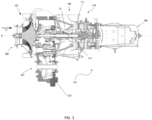
- FIG. 1 is a cross-sectional view of a gas turbine engine system 100.
- the gas turbine engine system 100 may supply power to and/or provide propulsion of an aircraft.
- the aircraft may include a helicopter, an airplane, an unmanned air vehicle, a fixed wing vehicle, a variable wing vehicle, a rotary wing vehicle, an unmanned combat aerial vehicle, a tailless aircraft, a hover craft, and any other airborne vehicle.
- gas turbine engine system 100 may be utilized in a configuration unrelated to an aircraft such as, but not limited to, an industrial application, an energy application, a power plant, a pumping set, a marine application (for example, for naval propulsion), a weapon system, a security system, a perimeter defense or security system.
- the gas turbine engine system 100 may take a variety of forms in various embodiments. Though depicted as a two-spool engine having a centrifugal compressor and axial flow gas generator and power turbine stages, in some forms the gas turbine engine system 100 may have one or multiple spools and/or may be any form of axial flow engine or mixed centrifugal/axial flow engine. In some forms, the gas turbine engine system 100 may be a turboprop, a turbofan, a turboshaft engine, APU, or a generator set, or other turbomachinery applications. Furthermore, the gas turbine engine system 100 may be an adaptive cycle and/or variable cycle engine. Other variations are also contemplated.
- the gas turbine engine system 100 may include an intake section 120, a compressor section 170, a combustion section 150, a turbine section 110, and an exhaust section 130.
- fluid received from the intake section 120 such as air, travels along the direction D1 and may be compressed within the compressor section 170.
- the compressed fluid may then be mixed with fuel and the mixture may be burned in the combustion section 150.
- the combustion section 150 may include any suitable fuel injection and combustion mechanisms.
- the hot, high pressure fluid may then pass through the turbine section 110 to extract energy from the fluid and cause a turbine shaft 140 to rotate, which in turn drives the compressor section 170.
- Discharge fluid may exit the exhaust section 130.
- the hot, high pressure fluid passes through the turbine section 110 during operation of the gas turbine engine system 100.
- the turbines section 110 causes the turbine rotors in turbine section 110 to rotate.
- the rotating turbines 112 may turn a shaft 140 in a rotational direction D2, for example.
- the blades 112 may rotate around an axis of rotation, which may correspond to a centerline X of the turbine 110 in some examples.
- the gas turbine engine system 100 may include a power transfer 180 in the form of a transmission or gearbox.
- the power transfer 180 may extract energy from the engine output in the form of torque at an angular velocity, and transfer such energy to other components within an aircraft.
- the power transfer 180 may transfer energy extracted from the engine to one or more propulsors.
- propulsor or “propulsors” is defined as a helicopter rotor, an airplane propeller, a ducted fan, or other mechanical device (such as, but not limited to, generators for electrical power generation) that is rotational driven by a motor to provide propulsion or work.
- a centrifugal air-oil separator system 210 is situated inside a gear box housing 200 of the gas turbine engine system 100. In other examples, the centrifugal air-oil separator system 210 may be situated inside an oil system housing of a gas turbine engine sump.
- FIG. 2 is an exploded view of an example centrifugal air-oil separator system 210.
- the centrifugal air-oil separator system 210 includes a gear 250, located on a rotatable shaft 220, and a bolt-on breather 270 having a first part 270a and/or a second part 270b, which may be joined together by fasteners 290.
- the breather 270 may be a one-piece, in which the breather 270 consists of only the first part 270a or the second part 270b.
- the shaft 220 includes an axially extending bore 230 formed at least partially through the shaft 220 supporting the gear 250.
- the shaft 220 may be rotatable by a power takeoff from the gas turbine engine system 100, a shaft of the gas turbine engine system 100 or other rotatable component of the gas turbine engine system 100.
- the bolt-on breather 270 rotates in response to the rotation of the gear 250.
- each of the components, the breather 270, the gear 250, and the shaft 220 may be separately constructed and fitted together in various configurations.
- the breather 270 may be mounted on the shaft 220 independent from and in contiguous contact with the gear 250.
- the breather 270 may be bolted to the gear 250 independent from the shaft 220.
- the breather 270 may be mounted on the shaft 220 without the gear 250 present.
- FIG. 3 illustrates a cross-sectional view of an example gear shaft in the air-oil separator system 210.
- a gear 250 is integral to or mounted on an outer surface of a shaft 220 and radially extending away from the shaft 220.
- the gear 250 includes gear teeth 300, a gear rim 350, and a gear web 310, which may include an inner shoulder 360.
- the gear 250 may include a plurality of axial holes 260 spaced between a plurality of angularly spaced radial passageways 240 in the shaft 220.
- One purpose of including axial holes 260 in the gear 250 is to reduce weight of the gear 250.
- the gear 250 may not include any axial holes 260.
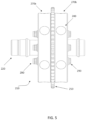
- FIG. 4 illustrates a perspective view of an example centrifugal air-oil separator system 210 with a bolt-on breather 270 having a first part 270a and a second part 270b.
- FIG. 5 is a side view of the centrifugal air-oil separator system 210 of FIG. 4 .
- each of the first part 270a and the second part 270b are mounted on the shaft 220 and are contiguously coupled with opposite sides of the gear 250.
- the first part 270a and the second part 270b are in contiguous contact with the gear web 310 ( FIG. 3 ).
- the first part 270a and the second part 270b are in contiguous contact with at least one of the gear inner shoulder 360 or the gear rim 350 ( FIG. 3 ).
- the bolt-on breather 270 consists of the first part 270a or the second part 270b mounted on the shaft 220 and is in contiguous contact with at least one of the gear web 310, the gear inner shoulder 360, or the gear rim 350.
- the first part 270a or the second part 270b is not mounted on the shaft 220 but is in contiguous contact with at least one of the gear web 310, the gear inner shoulder 360, or the gear rim 350.
- each of the first part 270a and/or the second part 270b may have a plurality of axial holes 280 that may align with the plurality of axial holes 260 on the gear 250. In other examples, the plurality of axial holes 280 are not aligned with the plurality of axial holes 260 on the gear 250.
- the first part 270a and/or the second part 270b extend radially outward from the shaft 220, independent of the predetermined radial distance of the gear 250. In the example shown in FIG. 4 , the first part 270a and the second part 270b are illustrated as less than the predetermined radial distance of the gear 250.
- first part 270a and/or the second part 270b of the breather 270 are contiguously coupled with the gear 250 by fasteners 290, such as threaded bolts and nuts, with the bolts extending through the first part 270a, the gear 250, and the second part 270b.
- fasteners 290 may be extended through one of the first and second parts 270a and/or 270b, incorporating threads in 270a or 270b to couple the parts.
- the first part 270a and/or the second part 270b may be press-fit onto the shaft 220.
- first part 270a and/or the second part 270b are pressed into contiguous contact with the gear 250 in opposite directions by fasteners 290, which may further include at least one spanner nut, with the first part 270a and/or the second part 270b being held against the gear 250 by compression with the spanner nut.
- fasteners 290 may further include at least one spanner nut, with the first part 270a and/or the second part 270b being held against the gear 250 by compression with the spanner nut.
- any hardware that mechanically joins or affixes the breather 270 to the gear 250 may be used as fasteners.
- the fasteners are used to create non-permanent joints; that is, joints that can be removed or dismantled without damaging the joining components (e.g., the first and second parts 270a and 270b).
- Examples of the fasteners 290 may be bolts, screws, nuts, grommets, rivets, studs, washers, rings, pins, spacers, clips, or ties, and combinations thereof.
- the fasteners 290 may be made of metal or plastic.
- plastic snaps may be featured on the first and second parts 270a and 270b to engage with the shaft 220. Any number of fasteners 290 can be included, for example, four to eight fasteners are included. In one example, six sets of nuts and bolts are used.
- O-ring seals, press fits or other sealing products may be incorporated to seal connections between the components.
- O-ring seals are used on the shaft 220 to seal the connections between the first and second parts 270a and 270b of the bolt-on breather 270 and the shaft 220.
- O-ring seals are placed on the bolt-on breather 270 to accomplish sealing with the shaft 220.
- O-ring seals may not be used and a press fit serves as the sealing function between the breather 270 and the shaft 220.
- FIG. 6 is a sectional view of the centrifugal air-oil separator system 210 of FIG. 4 .
- each of the first part 270a and the second part 270b of the bolt-on breather 270 may include a plurality of angularly spaced radial passageways 240 through a respective body of the first part 270a and the second part 270b to receive an air-oil mist from the engine, separating the oil from the air, and allow the air to enter the bore 230.
- the plurality of passageways 240 on the breather 270 extend radially outward and communicate with the cavity which opens to the bore 230 via a plurality of radial holes 330 in the shaft 220.
- the geometry of the passageways 240 may be adjusted to enhance the air and oil separation.
- the passageways 240 may be of any shape and size.
- the passageways 240 have a shape different from a circular opening or any radial holes.
- the adjustments may be achieved by using manufacturing methods selected from, but not limited to, machining, casting, additive layer manufacturing (ALM), extrusion, pressing, or injection molding or another manufacturing method known in the art.
- the breather 270 includes both the first part 270a and the second part 270b, and the passageways 240 in the first part 270a and the passageways 240 in the second part 270b provide fluid communication between the first part 270a and the second part 270b through the gear web 310.
- the passageways 240 are not in communication between the first part 270a and the second part 270b.
- the radial holes 330 are cross-drilled into the shaft 220.
- the air-oil separator system 210 utilizes the centrifugal forces generated by rotation of the gears 250 and the bolt-on breather 270 to extract oil from the air-oil mist collected inside the gearbox 180 and divert the extracted liquid oil out the system while air passes through the radial holes 330 into the bore 230.
- the air-oil mixture in the form of oil mist flows into the bolt-on breather 270 through the plurality of radial passageways 240 through outlet openings 320a ( FIG. 6 ).
- the lighter air is not significantly affected by the centrifugal force and flows to the radial holes 330 on the shaft 220 through inlet openings 320b ( FIG.
- the air-oil separator system 210 efficiently removes the oil from the air, and is a function of the gearbox pressure, mass flow rate of the air, and the expected oil percentage in the air. In some examples, the gearbox pressure is typically about 5 psi.
- the illustrated air-oil separator system is just one example, in other examples, other configurations are possible. For example, as the mass flow rate of the air increases, additional passageways 240 may be added to increase the surface areas on the bolt-on breather 270.
- a unique feature of the air-oil separator system 210 may be the selection of different materials for the gear shaft and the breather components.
- the system is designed in such a way to provide significant weight savings for the engine by selecting air-oil separator material that minimizes component weight while meeting component design criteria.
- the materials used for the shaft 220 may be a high strength and durable material, such as steel, in order to properly support the gears and bearing loads, while the breather components 270 of the air-oil separator system 210 may be lightweight materials with flexibility so as to adopt the geometry of the gear shaft.
- the bolt-on breather 270 having the first part 270a and/or the second part 270b can be made of any material that is of equal or lower density than the steel materials used for the gear 250 and the shaft 220, which can withstand operating temperatures in the range from about -50 °C to 200 °C.
- the breather 270 having the first part 270a and/or the second part 270b are made of a material selected from, but not limited to, metals or metal alloys, ceramics, polymers, or plastics. Suitable metals or metal alloys may be selected from, but not limited to, steel, aluminum, magnesium, titanium, beryllium and alloys thereof.
- Suitable ceramics may be selected from the group consisting of alumina, carbide, boride, nitride, and combinations thereof.
- Suitable polymers may be selected from the group consisting of polyethylene, polypropylene, polyesters, nylon, and cellulose.
- Suitable plastics are selected from the group consisting of polyamide, polyetheretherketone, polyphenylensulfide, polyimide, polyphenylsulfone, polysulfone, polyethersulfone, polyetetrafluoroethylene, polyetherimide and polyvinylidene fluoride.
- the gear shaft components of the air-oil separator system 210 can be made of any high strength steels, preferably, aerospace grade steels.
- the high strength steels may have a tensile strength higher than 800 MPa, and a yield strength over 500 MPa.
- the gear 250 and the shaft 220 are made of a second material selected from, but not limited to, alloy steels, carbon steels, or stainless steels.
- the bolt-on breather 270 may be made with aluminum to reduce the gear assembly weight by as much as 40% when compared with gear steel and in other examples, the bolt-on breather 270 may be made with plastic to reduce the gear assembly weight by as much as 70% when compared with gear steel.
- a plastic breather also has the potential to utilize internal plastic snaps which further reduces the weight of the air-oil separator system 210 by eliminating use of metal bolts.
- gear 250 containing web 310 defined as the area between the gear teeth and the gear shaft, is susceptible to dynamic natural resonant frequencies that occur within the normal operating speed range of the gearbox. These frequencies can cause premature failure of the gears and either need to be tuned out of the operating range or a damping mechanism employed.
- Apply a damping coating or incorporate damping rings into the design to dampen the dynamic response of the gear web are possible solutions.
- Another solution is incorporating a bolt-on breather 270 to provide the desired damping effects without the need to apply a damping coating or damping rings to the gear, which ultimately saves cost and provides additional weight savings for the engine.
- the first part 270a and the second part 270b are each utilized to dampen the dynamic response of the gear web by coupling with the gear web 310 and/or the gear rim 350.
- the subject-matter of the disclosure may also relate, among others, to the following aspects:
- a first aspect relates to a centrifugal air-oil separator system for separating oil particles from air in a gas turbine engine system.
- the centrifugal air-oil separator system includes a rotatable shaft journaled within a housing of the gas turbine engine system, the shaft including an axially extending bore formed at least partially through the shaft; a gear integral to or mounted on an outer surface of the shaft and radially extending away from the shaft, the gear includes gear teeth and a gear web; and a breather mounted on the shaft and independent from and in contiguous contact with the gear, wherein the shaft has a plurality of angularly spaced passageways extending radially outward through the shaft from the bore, wherein the breather includes a plurality of radial holes respectively aligned for fluid communication with the plurality of passageways in the shaft.
- a second aspect relates to the centrifugal air-oil separator system of the first aspect, wherein the breather includes at least one of a first part or a second part, wherein the at least one of the first part or the second part are mounted on the shaft and in contiguous contact with the gear.
- a third aspect relates to the centrifugal air-oil separator system of the first aspect, wherein the breather includes a first part and a second part, wherein the first part and the second part are mounted on the shaft and in contiguous contact with the gear.
- a fourth aspect relates to the centrifugal air-oil separator system of the first aspect, wherein the breather includes a first part and a second part, and the first part and the second part are contiguously coupled with the gear by fasteners extending through the first part, the gear, and the second part.
- a fifth aspect relates to the centrifugal air-oil separator system of the fourth aspect, wherein the first part and the second part are maintained in contiguous contact with at least one of the gear web, the gear inner shoulder, or the gear rim in opposite directions by the fastener.
- a sixth aspect relates to the centrifugal air-oil separator system of the second aspect, further including at least one spanner nut on the shaft, wherein the at least one of the first part or the second part are held against the shaft or gear by compression with the spanner nut.
- a seventh aspect relates to the centrifugal air-oil separator system of the second aspect, wherein the at least one of the first part or the second part are press-fit onto the shaft.
- An eighth aspect relates to the centrifugal air-oil separator system of the second aspect, further including an O-ring seal between the first part and the shaft, or an O-ring seal between and the second part and the shaft.
- a ninth aspect relates to the centrifugal air-oil separator system of the second aspect, wherein the at least one of the first part or the second part are used to dampen a dynamic response of the gear web.
- a tenth aspect relates to the centrifugal air-oil separator system of the first aspect, wherein the plurality of radial holes are aligned with the plurality of radial passageways to receive an air-oil mixture from the engine system and provide communication of at least air to the bore.
- An eleventh aspect relates to the centrifugal air-oil separator system of the first aspect, wherein the housing is a gearbox housing, and the shaft is a rotatable driven by a gas turbine engine.
- a twelfth aspect relates to the centrifugal air-oil separator system of the first aspect, wherein the housing is an oil system housing of a gas turbine engine sump, and the shaft is a rotatable shaft in the gas turbine engine sump.
- a thirteenth aspect relates to the centrifugal air-oil separator system of the first aspect, wherein the breather is made of a first material selected from metals or metal alloys, ceramics, polymers, or plastics, and wherein each of the gear and the shaft are made of a second material selected from alloy steels, carbon steels or stainless steels.
- a fourteenth aspect relates to the centrifugal air-oil separator system of the thirteenth aspect, wherein the metals or metal alloys are selected from steel, aluminum, magnesium, titanium, beryllium or alloys thereof.
- a fifteenth aspect relates to the centrifugal air-oil separator system of the thirteenth aspect, wherein the ceramics are selected from the group consisting of alumina, carbide, boride, nitride, and combinations thereof.
- a sixteenth aspect relates to the centrifugal air-oil separator system of the thirteenth aspect, wherein the polymers are selected from the group consisting of polyethylene, polypropylene, polyesters, nylon, and cellulose.
- a seventeenth aspect relates to the centrifugal air-oil separator system of the thirteenth aspect, wherein the plastics are selected from the group consisting of polyamide, polyetheretherketone, polyphenylensulfide, polyimide, polyphenylsulfone, polysulfone, polyethersulfone, polyetetrafluoroethylene, polyetherimide and polyvinylidene fluoride.
- An eighteenth aspect relates to the centrifugal air-oil separator system of the thirteenth aspect, wherein the first material is equal to or lighter in density than the second material.
- a nineteenth aspect relates to the centrifugal air-oil separator system of the second aspect, wherein each of the at least one of the first part or the second part includes a plurality of angularly spaced passageways and the passageways in the at least one of the first part or the second part are formed by a manufacturing method selected from machining, casting, additive layer manufacturing, extrusion, pressing, or injection molding.
- a twentieth aspect relates to the centrifugal air-oil separator system of the nineteenth aspect, wherein the breather includes both the first part and the second part, and the passageways in the first part and the passageways in the second part provide fluid communication between the first part and the second part through the gear web.
Landscapes
- Engineering & Computer Science (AREA)
- Chemical & Material Sciences (AREA)
- Combustion & Propulsion (AREA)
- Mechanical Engineering (AREA)
- General Engineering & Computer Science (AREA)
- Chemical Kinetics & Catalysis (AREA)
- Lubrication Details And Ventilation Of Internal Combustion Engines (AREA)
Abstract
A centrifugal air-oil separator system for a gas turbine engine system is described. The air-oil separator system has a rotatable shaft (220) and the shaft includes an axially extending bore (230) formed at least partially through the shaft. A gear (250) is integral to or mounted on an outer surface of the shaft. The air-oil separator system also includes a bolt-on breather (270) mounted on the shaft and independent from and in contiguous contact with the gear (250) to assist in separating the oil from the air. Various types of materials may be utilized in the construction of the air-oil separator system.
Description
- This disclosure relates to air-oil separator systems in gas turbine engines and gearboxes and, in particular, to a shaft mounted centrifugal air-oil separator system.
- Air-oil separator systems are used in gas turbine engines to separate oil from the air in the interior of a transmission or gearbox to reduce oil consumption, lower emissions, and keep the engine operating efficiently. An improved, weight saving air-oil separator system would be advantageous.
- The embodiments may be better understood with reference to the following drawing(s) and description. The components in the figures are not necessarily to scale. Moreover, in the figures, like-referenced numerals designate corresponding parts throughout the different views.
-
FIG. 1 is a cross-sectional view of an example gas turbine engine system. -
FIG. 2 is an exploded view of an example centrifugal air-oil separator system with a bolt-on breather. -
FIG. 3 is a cross-sectional view of an example gear shaft of a centrifugal air-oil separator system. -
FIG. 4 is a perspective view of an example centrifugal air-oil separator system with a bolt-on breather. -
FIG. 5 is a side view of an example centrifugal air-oil separator system with a bolt-on breather. -
FIG. 6 is a sectional view of an example centrifugal air-oil separator system with a bolt-on breather. - As lubricating oil is introduced into a gearbox or bearing sump during gas turbine engine operation, windage results in the oil being entrained in the air. To reduce oil consumption and churning in a gearbox or bearing sump, it is important to separate this oil from the air. Physical interaction with a shaft mounted air-oil separator system (also known as a breather) may help coalesce the finely dispersed oil particles into larger droplets. Because liquid oil is heavier than air, the oil may be separated out and forces, such as centrifugal forces, may be used to help drive the oil toward the outside of the structure where the oil may be returned to an oil reservoir in the engine. The air separated from the oil may be vented through the air-oil separator structure and out to the atmosphere. By way of an introductory example, a centrifugal air-oil separator system for a gas turbine engine system has a rotatable shaft and the shaft includes an axially extending bore formed at least partially through the shaft. A gear is integral to or mounted on an outer surface of the shaft. The air-oil separator system also includes a bolt-on breather having a first part and/or a second part, each of the first part and/or the second part positioned to mount on the shaft and be contiguously coupled with the gear to assist in separating the oil from the air. As used herein, the term "bolt-on" refers to an accessory that can be fastened or attached onto a component. Various types of materials may be utilized in the construction of the air-oil separator system.
- In connection with the centrifugal air-oil separator system,
FIG. 1 is a cross-sectional view of a gasturbine engine system 100. In some examples, the gasturbine engine system 100 may supply power to and/or provide propulsion of an aircraft. Examples of the aircraft may include a helicopter, an airplane, an unmanned air vehicle, a fixed wing vehicle, a variable wing vehicle, a rotary wing vehicle, an unmanned combat aerial vehicle, a tailless aircraft, a hover craft, and any other airborne vehicle. In addition, the gasturbine engine system 100 may be utilized in a configuration unrelated to an aircraft such as, but not limited to, an industrial application, an energy application, a power plant, a pumping set, a marine application (for example, for naval propulsion), a weapon system, a security system, a perimeter defense or security system. - The gas
turbine engine system 100 may take a variety of forms in various embodiments. Though depicted as a two-spool engine having a centrifugal compressor and axial flow gas generator and power turbine stages, in some forms the gasturbine engine system 100 may have one or multiple spools and/or may be any form of axial flow engine or mixed centrifugal/axial flow engine. In some forms, the gasturbine engine system 100 may be a turboprop, a turbofan, a turboshaft engine, APU, or a generator set, or other turbomachinery applications. Furthermore, the gasturbine engine system 100 may be an adaptive cycle and/or variable cycle engine. Other variations are also contemplated. - The gas
turbine engine system 100 may include anintake section 120, acompressor section 170, acombustion section 150, aturbine section 110, and anexhaust section 130. During operation of the gasturbine engine system 100, fluid received from theintake section 120, such as air, travels along the direction D1 and may be compressed within thecompressor section 170. The compressed fluid may then be mixed with fuel and the mixture may be burned in thecombustion section 150. Thecombustion section 150 may include any suitable fuel injection and combustion mechanisms. The hot, high pressure fluid may then pass through theturbine section 110 to extract energy from the fluid and cause aturbine shaft 140 to rotate, which in turn drives thecompressor section 170. Discharge fluid may exit theexhaust section 130. - As noted above, the hot, high pressure fluid passes through the
turbine section 110 during operation of the gasturbine engine system 100. As the fluid flows through theturbines section 110, it causes the turbine rotors inturbine section 110 to rotate. The rotatingturbines 112 may turn ashaft 140 in a rotational direction D2, for example. Theblades 112 may rotate around an axis of rotation, which may correspond to a centerline X of theturbine 110 in some examples. In some examples, the gasturbine engine system 100 may include apower transfer 180 in the form of a transmission or gearbox. Thepower transfer 180 may extract energy from the engine output in the form of torque at an angular velocity, and transfer such energy to other components within an aircraft. In an example of a helicopter or airplane, thepower transfer 180 may transfer energy extracted from the engine to one or more propulsors. As used herein, the term "propulsor" or "propulsors" is defined as a helicopter rotor, an airplane propeller, a ducted fan, or other mechanical device (such as, but not limited to, generators for electrical power generation) that is rotational driven by a motor to provide propulsion or work. - In one example, a centrifugal air-
oil separator system 210 is situated inside agear box housing 200 of the gasturbine engine system 100. In other examples, the centrifugal air-oil separator system 210 may be situated inside an oil system housing of a gas turbine engine sump. -
FIG. 2 is an exploded view of an example centrifugal air-oil separator system 210. The centrifugal air-oil separator system 210 includes agear 250, located on arotatable shaft 220, and a bolt-on breather 270 having afirst part 270a and/or asecond part 270b, which may be joined together byfasteners 290. In some examples, the breather 270 may be a one-piece, in which the breather 270 consists of only thefirst part 270a or thesecond part 270b. Theshaft 220 includes an axially extendingbore 230 formed at least partially through theshaft 220 supporting thegear 250. Theshaft 220 may be rotatable by a power takeoff from the gasturbine engine system 100, a shaft of the gasturbine engine system 100 or other rotatable component of the gasturbine engine system 100. The bolt-on breather 270 rotates in response to the rotation of thegear 250. As opposed to an integral design, each of the components, the breather 270, thegear 250, and theshaft 220 may be separately constructed and fitted together in various configurations. For example, the breather 270 may be mounted on theshaft 220 independent from and in contiguous contact with thegear 250. In some examples, the breather 270 may be bolted to thegear 250 independent from theshaft 220. In other examples, the breather 270 may be mounted on theshaft 220 without thegear 250 present. -
FIG. 3 illustrates a cross-sectional view of an example gear shaft in the air-oil separator system 210. InFIG. 3 , agear 250 is integral to or mounted on an outer surface of ashaft 220 and radially extending away from theshaft 220. Thegear 250 includesgear teeth 300, agear rim 350, and agear web 310, which may include aninner shoulder 360. Optionally, thegear 250 may include a plurality ofaxial holes 260 spaced between a plurality of angularly spacedradial passageways 240 in theshaft 220. One purpose of includingaxial holes 260 in thegear 250 is to reduce weight of thegear 250. In some examples, thegear 250 may not include anyaxial holes 260. -
FIG. 4 illustrates a perspective view of an example centrifugal air-oil separator system 210 with a bolt-on breather 270 having afirst part 270a and asecond part 270b.FIG. 5 is a side view of the centrifugal air-oil separator system 210 ofFIG. 4 . As shown inFIGS. 4 and5 , each of thefirst part 270a and thesecond part 270b are mounted on theshaft 220 and are contiguously coupled with opposite sides of thegear 250. For example, thefirst part 270a and thesecond part 270b are in contiguous contact with the gear web 310 (FIG. 3 ). In other examples, thefirst part 270a and thesecond part 270b are in contiguous contact with at least one of the gearinner shoulder 360 or the gear rim 350 (FIG. 3 ). In one example, the bolt-on breather 270 consists of thefirst part 270a or thesecond part 270b mounted on theshaft 220 and is in contiguous contact with at least one of thegear web 310, the gearinner shoulder 360, or thegear rim 350. In other examples, thefirst part 270a or thesecond part 270b is not mounted on theshaft 220 but is in contiguous contact with at least one of thegear web 310, the gearinner shoulder 360, or thegear rim 350. - Additionally, each of the
first part 270a and/or thesecond part 270b may have a plurality ofaxial holes 280 that may align with the plurality ofaxial holes 260 on thegear 250. In other examples, the plurality ofaxial holes 280 are not aligned with the plurality ofaxial holes 260 on thegear 250. Thefirst part 270a and/or thesecond part 270b extend radially outward from theshaft 220, independent of the predetermined radial distance of thegear 250. In the example shown inFIG. 4 , thefirst part 270a and thesecond part 270b are illustrated as less than the predetermined radial distance of thegear 250. - In the examples, the
first part 270a and/or thesecond part 270b of the breather 270 are contiguously coupled with thegear 250 byfasteners 290, such as threaded bolts and nuts, with the bolts extending through thefirst part 270a, thegear 250, and thesecond part 270b. In other examples, thefasteners 290 may be extended through one of the first andsecond parts 270a and/or 270b, incorporating threads in 270a or 270b to couple the parts. Alternatively, or in addition, thefirst part 270a and/or thesecond part 270b may be press-fit onto theshaft 220. Additionally, thefirst part 270a and/or thesecond part 270b are pressed into contiguous contact with thegear 250 in opposite directions byfasteners 290, which may further include at least one spanner nut, with thefirst part 270a and/or thesecond part 270b being held against thegear 250 by compression with the spanner nut. In the examples, any hardware that mechanically joins or affixes the breather 270 to thegear 250 may be used as fasteners. In general, the fasteners are used to create non-permanent joints; that is, joints that can be removed or dismantled without damaging the joining components (e.g., the first andsecond parts fasteners 290 may be bolts, screws, nuts, grommets, rivets, studs, washers, rings, pins, spacers, clips, or ties, and combinations thereof. Thefasteners 290 may be made of metal or plastic. In some examples, plastic snaps may be featured on the first andsecond parts shaft 220. Any number offasteners 290 can be included, for example, four to eight fasteners are included. In one example, six sets of nuts and bolts are used. In some examples, O-ring seals, press fits or other sealing products may be incorporated to seal connections between the components. In one example, O-ring seals are used on theshaft 220 to seal the connections between the first andsecond parts shaft 220. In other examples, O-ring seals are placed on the bolt-on breather 270 to accomplish sealing with theshaft 220. In other examples, O-ring seals may not be used and a press fit serves as the sealing function between the breather 270 and theshaft 220. -
FIG. 6 is a sectional view of the centrifugal air-oil separator system 210 ofFIG. 4 . As shown inFIG. 6 , each of thefirst part 270a and thesecond part 270b of the bolt-on breather 270 may include a plurality of angularly spacedradial passageways 240 through a respective body of thefirst part 270a and thesecond part 270b to receive an air-oil mist from the engine, separating the oil from the air, and allow the air to enter thebore 230. The plurality ofpassageways 240 on the breather 270 extend radially outward and communicate with the cavity which opens to thebore 230 via a plurality ofradial holes 330 in theshaft 220. In addition, the geometry of thepassageways 240, such as the shape and size, may be adjusted to enhance the air and oil separation. Thepassageways 240 may be of any shape and size. In some examples, thepassageways 240 have a shape different from a circular opening or any radial holes. The adjustments may be achieved by using manufacturing methods selected from, but not limited to, machining, casting, additive layer manufacturing (ALM), extrusion, pressing, or injection molding or another manufacturing method known in the art. In some examples, the breather 270 includes both thefirst part 270a and thesecond part 270b, and thepassageways 240 in thefirst part 270a and thepassageways 240 in thesecond part 270b provide fluid communication between thefirst part 270a and thesecond part 270b through thegear web 310. In other examples, thepassageways 240 are not in communication between thefirst part 270a and thesecond part 270b. In the example shown inFIG. 6 , theradial holes 330 are cross-drilled into theshaft 220. - During operation, the air-
oil separator system 210 utilizes the centrifugal forces generated by rotation of thegears 250 and the bolt-on breather 270 to extract oil from the air-oil mist collected inside thegearbox 180 and divert the extracted liquid oil out the system while air passes through theradial holes 330 into thebore 230. As thegear 250 and the bolt-on breather 270 are spinning, the air-oil mixture in the form of oil mist flows into the bolt-on breather 270 through the plurality ofradial passageways 240 throughoutlet openings 320a (FIG. 6 ). The lighter air is not significantly affected by the centrifugal force and flows to the radial holes 330 on theshaft 220 throughinlet openings 320b (FIG. 6 ) and then exits to the environment via thebore 230 with minimum oil contained in the flowing air. The heavier oil particles are impacted by the centrifugal force to coalesce and/or flow radially outward through theradial passageways 240 and are spun back out of theoutlet openings 320a to return to the gearbox 180 (FIG. 1 ), or bearing sump depending on the application. The air-oil separator system 210 efficiently removes the oil from the air, and is a function of the gearbox pressure, mass flow rate of the air, and the expected oil percentage in the air. In some examples, the gearbox pressure is typically about 5 psi. The illustrated air-oil separator system is just one example, in other examples, other configurations are possible. For example, as the mass flow rate of the air increases,additional passageways 240 may be added to increase the surface areas on the bolt-on breather 270. - A unique feature of the air-
oil separator system 210 may be the selection of different materials for the gear shaft and the breather components. The system is designed in such a way to provide significant weight savings for the engine by selecting air-oil separator material that minimizes component weight while meeting component design criteria. For example, the materials used for theshaft 220 may be a high strength and durable material, such as steel, in order to properly support the gears and bearing loads, while the breather components 270 of the air-oil separator system 210 may be lightweight materials with flexibility so as to adopt the geometry of the gear shaft. - The bolt-on breather 270 having the
first part 270a and/or thesecond part 270b can be made of any material that is of equal or lower density than the steel materials used for thegear 250 and theshaft 220, which can withstand operating temperatures in the range from about -50 °C to 200 °C. In some examples, the breather 270 having thefirst part 270a and/or thesecond part 270b are made of a material selected from, but not limited to, metals or metal alloys, ceramics, polymers, or plastics. Suitable metals or metal alloys may be selected from, but not limited to, steel, aluminum, magnesium, titanium, beryllium and alloys thereof. Suitable ceramics may be selected from the group consisting of alumina, carbide, boride, nitride, and combinations thereof. Suitable polymers may be selected from the group consisting of polyethylene, polypropylene, polyesters, nylon, and cellulose. Suitable plastics are selected from the group consisting of polyamide, polyetheretherketone, polyphenylensulfide, polyimide, polyphenylsulfone, polysulfone, polyethersulfone, polyetetrafluoroethylene, polyetherimide and polyvinylidene fluoride. - The gear shaft components of the air-
oil separator system 210 can be made of any high strength steels, preferably, aerospace grade steels. The high strength steels may have a tensile strength higher than 800 MPa, and a yield strength over 500 MPa. In some examples, thegear 250 and theshaft 220 are made of a second material selected from, but not limited to, alloy steels, carbon steels, or stainless steels. - In the examples, the bolt-on breather 270 may be made with aluminum to reduce the gear assembly weight by as much as 40% when compared with gear steel and in other examples, the bolt-on breather 270 may be made with plastic to reduce the gear assembly weight by as much as 70% when compared with gear steel. A plastic breather also has the potential to utilize internal plastic snaps which further reduces the weight of the air-
oil separator system 210 by eliminating use of metal bolts. - Another benefit to designing the air-
oil separator system 210 using different materials for each of its components comes in the form of damping.Gear 250 containingweb 310, defined as the area between the gear teeth and the gear shaft, is susceptible to dynamic natural resonant frequencies that occur within the normal operating speed range of the gearbox. These frequencies can cause premature failure of the gears and either need to be tuned out of the operating range or a damping mechanism employed. Apply a damping coating or incorporate damping rings into the design to dampen the dynamic response of the gear web are possible solutions. Another solution is incorporating a bolt-on breather 270 to provide the desired damping effects without the need to apply a damping coating or damping rings to the gear, which ultimately saves cost and provides additional weight savings for the engine. In some examples, thefirst part 270a and thesecond part 270b are each utilized to dampen the dynamic response of the gear web by coupling with thegear web 310 and/or thegear rim 350. - While various embodiments have been described, it will be apparent to those of ordinary skill in the art that many more embodiments and implementations are possible. Accordingly, the embodiments described herein are examples, not the only possible embodiments and implementations.
- The subject-matter of the disclosure may also relate, among others, to the following aspects:
- A first aspect relates to a centrifugal air-oil separator system for separating oil particles from air in a gas turbine engine system. The centrifugal air-oil separator system includes a rotatable shaft journaled within a housing of the gas turbine engine system, the shaft including an axially extending bore formed at least partially through the shaft; a gear integral to or mounted on an outer surface of the shaft and radially extending away from the shaft, the gear includes gear teeth and a gear web; and a breather mounted on the shaft and independent from and in contiguous contact with the gear, wherein the shaft has a plurality of angularly spaced passageways extending radially outward through the shaft from the bore, wherein the breather includes a plurality of radial holes respectively aligned for fluid communication with the plurality of passageways in the shaft.
- A second aspect relates to the centrifugal air-oil separator system of the first aspect, wherein the breather includes at least one of a first part or a second part, wherein the at least one of the first part or the second part are mounted on the shaft and in contiguous contact with the gear.
- A third aspect relates to the centrifugal air-oil separator system of the first aspect, wherein the breather includes a first part and a second part, wherein the first part and the second part are mounted on the shaft and in contiguous contact with the gear.
- A fourth aspect relates to the centrifugal air-oil separator system of the first aspect, wherein the breather includes a first part and a second part, and the first part and the second part are contiguously coupled with the gear by fasteners extending through the first part, the gear, and the second part.
- A fifth aspect relates to the centrifugal air-oil separator system of the fourth aspect, wherein the first part and the second part are maintained in contiguous contact with at least one of the gear web, the gear inner shoulder, or the gear rim in opposite directions by the fastener.
- A sixth aspect relates to the centrifugal air-oil separator system of the second aspect, further including at least one spanner nut on the shaft, wherein the at least one of the first part or the second part are held against the shaft or gear by compression with the spanner nut.
- A seventh aspect relates to the centrifugal air-oil separator system of the second aspect, wherein the at least one of the first part or the second part are press-fit onto the shaft.
- An eighth aspect relates to the centrifugal air-oil separator system of the second aspect, further including an O-ring seal between the first part and the shaft, or an O-ring seal between and the second part and the shaft.
- A ninth aspect relates to the centrifugal air-oil separator system of the second aspect, wherein the at least one of the first part or the second part are used to dampen a dynamic response of the gear web.
- A tenth aspect relates to the centrifugal air-oil separator system of the first aspect, wherein the plurality of radial holes are aligned with the plurality of radial passageways to receive an air-oil mixture from the engine system and provide communication of at least air to the bore.
- An eleventh aspect relates to the centrifugal air-oil separator system of the first aspect, wherein the housing is a gearbox housing, and the shaft is a rotatable driven by a gas turbine engine.
- A twelfth aspect relates to the centrifugal air-oil separator system of the first aspect, wherein the housing is an oil system housing of a gas turbine engine sump, and the shaft is a rotatable shaft in the gas turbine engine sump.
- A thirteenth aspect relates to the centrifugal air-oil separator system of the first aspect, wherein the breather is made of a first material selected from metals or metal alloys, ceramics, polymers, or plastics, and wherein each of the gear and the shaft are made of a second material selected from alloy steels, carbon steels or stainless steels.
- A fourteenth aspect relates to the centrifugal air-oil separator system of the thirteenth aspect, wherein the metals or metal alloys are selected from steel, aluminum, magnesium, titanium, beryllium or alloys thereof.
- A fifteenth aspect relates to the centrifugal air-oil separator system of the thirteenth aspect, wherein the ceramics are selected from the group consisting of alumina, carbide, boride, nitride, and combinations thereof.
- A sixteenth aspect relates to the centrifugal air-oil separator system of the thirteenth aspect, wherein the polymers are selected from the group consisting of polyethylene, polypropylene, polyesters, nylon, and cellulose.
- A seventeenth aspect relates to the centrifugal air-oil separator system of the thirteenth aspect, wherein the plastics are selected from the group consisting of polyamide, polyetheretherketone, polyphenylensulfide, polyimide, polyphenylsulfone, polysulfone, polyethersulfone, polyetetrafluoroethylene, polyetherimide and polyvinylidene fluoride.
- An eighteenth aspect relates to the centrifugal air-oil separator system of the thirteenth aspect, wherein the first material is equal to or lighter in density than the second material.
- A nineteenth aspect relates to the centrifugal air-oil separator system of the second aspect, wherein each of the at least one of the first part or the second part includes a plurality of angularly spaced passageways and the passageways in the at least one of the first part or the second part are formed by a manufacturing method selected from machining, casting, additive layer manufacturing, extrusion, pressing, or injection molding.
- A twentieth aspect relates to the centrifugal air-oil separator system of the nineteenth aspect, wherein the breather includes both the first part and the second part, and the passageways in the first part and the passageways in the second part provide fluid communication between the first part and the second part through the gear web.
- In addition to the features mentioned in each of the independent aspects enumerated above, some examples may show, alone or in combination, the optional features mentioned in the dependent aspects and/or as disclosed in the description above and shown in the figures.
Claims (15)
- A centrifugal air-oil separator system for separating oil particles from air in a gas turbine engine system (100), comprising:a rotatable shaft (220) journaled within a housing (200) of the gas turbine engine system (100), the shaft (220) including an axially extending bore (230) formed at least partially through the shaft (220);a gear (250) integral to or mounted on an outer surface of the shaft (220) and radially extending away from the shaft (220), the gear (250) comprises gear teeth (300) and a gear web (310); anda breather (270) mounted on the shaft (220) and independent from and in contiguous contact with the gear (250),wherein the shaft (220) has a plurality of angularly spaced passageways (240) extending radially outward through the shaft (220) from the bore (230), wherein the breather (270) includes a plurality of radial holes (330) respectively aligned for fluid communication with the plurality of passageways (240) in the shaft (220).
- The centrifugal air-oil separator system of claim 1, wherein the breather (270) comprises at least one of a first part (270a) and/or a second part (270b), wherein the at least one of the first part (270a) and/or the second part (270b) are mounted on the shaft (220) and in contiguous contact with the gear (250).
- The centrifugal air-oil separator system of claim 1 or 2, wherein the breather (270) comprises a first part (270a) and a second part (270b), and the first part (270a) and the second part (270b) are contiguously coupled with the gear (250) by fasteners (290) extending through the first part (270a), the gear (250), and the second part (270b).
- The centrifugal air-oil separator system of claim 3, wherein the first part (270a) and the second part (270b) are maintained in contiguous contact with at least one of the gear web (310), the gear inner shoulder (360), or the gear rim (350) in opposite directions by the fastener (290).
- The centrifugal air-oil separator system of claim 2, further comprising at least one spanner nut on the shaft (220), wherein the at least one of the first part (270a) or the second part (270b) are held against the shaft (220) or gear (250) by compression with the spanner nut.
- The centrifugal air-oil separator system of claim 2, wherein the at least one of the first part (270a) or the second part (270b) are press-fit onto the shaft (220).
- The centrifugal air-oil separator system of claim 2, further comprising an O-ring seal between the first part (270a) and the shaft (220), or an O-ring seal between the second part (270b) and the shaft (220).
- The centrifugal air-oil separator system of claim 2, wherein the at least one of the first part (270a) or the second part (270b) are used to dampen a dynamic response of the gear web (310).
- The centrifugal air-oil separator system of one of the preceding claims, wherein the plurality of radial holes (330) are aligned with the plurality of radial passageways (240) to receive an air-oil mixture from the engine system and provide communication of at least air to the bore (230).
- The centrifugal air-oil separator system of one of the preceding claims, wherein the housing (200) is a gear box housing, and the shaft (220) is a rotatable driven by a gas turbine engine, or
wherein the housing (200) is an oil system housing of a gas turbine engine sump, and the shaft (220) is a rotatable shaft (220) of the gas turbine engine sump. - The centrifugal air-oil separator system of one of the preceding claims, wherein the breather (270) is made of a first material selected from metals or metal alloys, ceramics, polymers, or plastics, and wherein each of the gear (250) and the shaft (220) are made of a second material selected from alloy steels, carbon steels, or stainless steels.
- The centrifugal air-oil separator system of claim 11, wherein the metals or metal alloys are selected from steel, aluminum, magnesium, titanium, beryllium or alloys thereof, and/orwherein the ceramics are selected from the group consisting of alumina, carbide, boride, nitride, and combinations thereof, and/orwherein the polymers are selected from the group consisting of polyethylene, polypropylene, polyesters, nylon, and cellulose, and/orwherein the plastics are selected from the group consisting of polyamide, polyetheretherketone, polyphenylensulfide, polyimide, polyphenylsulfone, polysulfone, polyethersulfone, polyetetrafluoroethylene, polyetherimide and polyvinylidene fluoride.
- The centrifugal air-oil separator system of claim 11, wherein the first material is equal to or lighter in density than the second material.
- The centrifugal air-oil separator system of claim 2, wherein each of the at least one of the first part (270a) or the second part (270b) includes a plurality of angularly spaced passageways (240) and the passageways (240) in the at least one of the first part (270a) or the second part (270b) are formed by a manufacturing method selected from machining, casting, additive layer manufacturing, extrusion, pressing, or injection molding.
- The centrifugal air-oil separator system of claim 14, wherein the breather (270) includes both the first part (270a) and the second part (270b), and the passageways (240) in the first part (270a) and the passageways (240) in the second part (270b) provide fluid communication between the first part (270a) and the second part (270b) through the gear web (310).
Applications Claiming Priority (1)
| Application Number | Priority Date | Filing Date | Title |
|---|---|---|---|
| US18/323,217 US12337336B2 (en) | 2023-05-24 | 2023-05-24 | Shaft mounted centrifugal air-oil separator system |
Publications (1)
| Publication Number | Publication Date |
|---|---|
| EP4467777A1 true EP4467777A1 (en) | 2024-11-27 |
Family
ID=90123029
Family Applications (1)
| Application Number | Title | Priority Date | Filing Date |
|---|---|---|---|
| EP24160832.2A Pending EP4467777A1 (en) | 2023-05-24 | 2024-03-01 | Shaft mounted centrifugal air-oil separator system |
Country Status (2)
| Country | Link |
|---|---|
| US (1) | US12337336B2 (en) |
| EP (1) | EP4467777A1 (en) |
Citations (6)
| Publication number | Priority date | Publication date | Assignee | Title |
|---|---|---|---|---|
| US6033450A (en) * | 1995-12-21 | 2000-03-07 | United Technologies Corporation | Deoiler shaft vortex separator |
| US20050217272A1 (en) * | 2004-03-31 | 2005-10-06 | Sheridan William G | Deoiler for a lubrication system |
| JP4490553B2 (en) * | 2000-04-28 | 2010-06-30 | 本田技研工業株式会社 | Auxiliary drive unit for gas turbine engine |
| CN105863847A (en) * | 2016-04-13 | 2016-08-17 | 中国科学院工程热物理研究所 | Bearing chamber axle center ventilating structure and gas turbine engine with same |
| EP3135882A1 (en) * | 2015-08-26 | 2017-03-01 | Honeywell International Inc. | Transverse mounted accessory gearbox |
| FR3064305A1 (en) * | 2017-03-21 | 2018-09-28 | Safran Helicopter Engines | CENTRIFUGAL DEGRAYER OF TURBOMACHINE |
Family Cites Families (6)
| Publication number | Priority date | Publication date | Assignee | Title |
|---|---|---|---|---|
| GB709646A (en) | 1951-07-12 | 1954-06-02 | Rolls Royce | Improvements in or relating to oil separator means for engine breather arrangements |
| US4217120A (en) | 1977-10-20 | 1980-08-12 | Sundstrand Corporation | Air-oil separator for aircraft gearbox |
| US20100107687A1 (en) * | 2008-11-06 | 2010-05-06 | Diki Andrian | Process for removing gaseous contaminants from a feed gas stream comprising methane and gaseous contaminants |
| DE102015209908A1 (en) * | 2015-05-29 | 2016-12-01 | Polytec Plastics Germany Gmbh & Co. Kg | Plate separator with welded plastic housing |
| FR3071418B1 (en) * | 2017-09-26 | 2019-09-13 | Safran Helicopter Engines | PIECE FOR TURBOMACHINE CENTRIFUGAL DEGREYER AND PROCESS FOR MANUFACTURING THE SAME |
| DE202019102394U1 (en) * | 2019-04-29 | 2020-07-30 | Woco Industrietechnik Gmbh | Centrifugal separator |
-
2023
- 2023-05-24 US US18/323,217 patent/US12337336B2/en active Active
-
2024
- 2024-03-01 EP EP24160832.2A patent/EP4467777A1/en active Pending
Patent Citations (6)
| Publication number | Priority date | Publication date | Assignee | Title |
|---|---|---|---|---|
| US6033450A (en) * | 1995-12-21 | 2000-03-07 | United Technologies Corporation | Deoiler shaft vortex separator |
| JP4490553B2 (en) * | 2000-04-28 | 2010-06-30 | 本田技研工業株式会社 | Auxiliary drive unit for gas turbine engine |
| US20050217272A1 (en) * | 2004-03-31 | 2005-10-06 | Sheridan William G | Deoiler for a lubrication system |
| EP3135882A1 (en) * | 2015-08-26 | 2017-03-01 | Honeywell International Inc. | Transverse mounted accessory gearbox |
| CN105863847A (en) * | 2016-04-13 | 2016-08-17 | 中国科学院工程热物理研究所 | Bearing chamber axle center ventilating structure and gas turbine engine with same |
| FR3064305A1 (en) * | 2017-03-21 | 2018-09-28 | Safran Helicopter Engines | CENTRIFUGAL DEGRAYER OF TURBOMACHINE |
Also Published As
| Publication number | Publication date |
|---|---|
| US12337336B2 (en) | 2025-06-24 |
| US20240390919A1 (en) | 2024-11-28 |
Similar Documents
| Publication | Publication Date | Title |
|---|---|---|
| US11346285B2 (en) | Compact accessory systems for a gas turbine engine | |
| US7993425B2 (en) | Free vortex air-oil separator | |
| US10729992B2 (en) | Centrifugal separator | |
| CN111089142B (en) | Epicyclic gearbox | |
| US8262344B2 (en) | Thermal management system for a gas turbine engine | |
| EP1582703B1 (en) | Gas turbine engine and method of separating oil from air in said gas turbine engine | |
| US12291980B2 (en) | Unducted rectifier for a turbomachine, turbomachine module and aircraft turbomachine | |
| EP4001595A1 (en) | Gas turbine engine with improved vigv shielding | |
| CN112443652B (en) | Gear assembly for an aircraft engine with a collector | |
| US11174756B2 (en) | Gas turbine engine and method for introducing oil in a gearbox arrangement | |
| US11149741B2 (en) | Variable pitch fan for a gas turbine engine | |
| US12337336B2 (en) | Shaft mounted centrifugal air-oil separator system | |
| US11879541B2 (en) | Oil scavenge system for a gearbox | |
| CN114198208B (en) | Air turbine starter | |
| CN111608953A (en) | Ice crystal protection for gas turbine engines | |
| CN111156194A (en) | Blade mounting | |
| US20080135336A1 (en) | Under race bearing lubrication system for gas turbine engines | |
| EP4361403A1 (en) | Conduit bushing with cellular material | |
| US20260085626A1 (en) | Oil tank return for an aircraft engine oil system | |
| US12497908B2 (en) | Turbine engine including a fan assembly having a damper | |
| EP4524366A2 (en) | Multi-piece injector nozzle for a turbine engine | |
| EP4552973A1 (en) | Compact aircraft engine with variable pitch propeller and oil transfer ring | |
| CA3287071A1 (en) | Oil tank return for an aircraft engine oil system |
Legal Events
| Date | Code | Title | Description |
|---|---|---|---|
| PUAI | Public reference made under article 153(3) epc to a published international application that has entered the european phase |
Free format text: ORIGINAL CODE: 0009012 |
|
| STAA | Information on the status of an ep patent application or granted ep patent |
Free format text: STATUS: THE APPLICATION HAS BEEN PUBLISHED |
|
| AK | Designated contracting states |
Kind code of ref document: A1 Designated state(s): AL AT BE BG CH CY CZ DE DK EE ES FI FR GB GR HR HU IE IS IT LI LT LU LV MC ME MK MT NL NO PL PT RO RS SE SI SK SM TR |
|
| STAA | Information on the status of an ep patent application or granted ep patent |
Free format text: STATUS: REQUEST FOR EXAMINATION WAS MADE |
|
| 17P | Request for examination filed |
Effective date: 20250522 |