EP3135882A1 - Transverse mounted accessory gearbox - Google Patents
Transverse mounted accessory gearbox Download PDFInfo
- Publication number
- EP3135882A1 EP3135882A1 EP16174673.0A EP16174673A EP3135882A1 EP 3135882 A1 EP3135882 A1 EP 3135882A1 EP 16174673 A EP16174673 A EP 16174673A EP 3135882 A1 EP3135882 A1 EP 3135882A1
- Authority
- EP
- European Patent Office
- Prior art keywords
- shaft
- gears
- gear
- coupled
- engagement surface
- Prior art date
- Legal status (The legal status is an assumption and is not a legal conclusion. Google has not performed a legal analysis and makes no representation as to the accuracy of the status listed.)
- Granted
Links
Images


Classifications
-
- F—MECHANICAL ENGINEERING; LIGHTING; HEATING; WEAPONS; BLASTING
- F02—COMBUSTION ENGINES; HOT-GAS OR COMBUSTION-PRODUCT ENGINE PLANTS
- F02C—GAS-TURBINE PLANTS; AIR INTAKES FOR JET-PROPULSION PLANTS; CONTROLLING FUEL SUPPLY IN AIR-BREATHING JET-PROPULSION PLANTS
- F02C7/00—Features, components parts, details or accessories, not provided for in, or of interest apart form groups F02C1/00 - F02C6/00; Air intakes for jet-propulsion plants
- F02C7/32—Arrangement, mounting, or driving, of auxiliaries
-
- F—MECHANICAL ENGINEERING; LIGHTING; HEATING; WEAPONS; BLASTING
- F05—INDEXING SCHEMES RELATING TO ENGINES OR PUMPS IN VARIOUS SUBCLASSES OF CLASSES F01-F04
- F05D—INDEXING SCHEME FOR ASPECTS RELATING TO NON-POSITIVE-DISPLACEMENT MACHINES OR ENGINES, GAS-TURBINES OR JET-PROPULSION PLANTS
- F05D2250/00—Geometry
- F05D2250/30—Arrangement of components
- F05D2250/31—Arrangement of components according to the direction of their main axis or their axis of rotation
- F05D2250/312—Arrangement of components according to the direction of their main axis or their axis of rotation the axes being parallel to each other
-
- F—MECHANICAL ENGINEERING; LIGHTING; HEATING; WEAPONS; BLASTING
- F05—INDEXING SCHEMES RELATING TO ENGINES OR PUMPS IN VARIOUS SUBCLASSES OF CLASSES F01-F04
- F05D—INDEXING SCHEME FOR ASPECTS RELATING TO NON-POSITIVE-DISPLACEMENT MACHINES OR ENGINES, GAS-TURBINES OR JET-PROPULSION PLANTS
- F05D2250/00—Geometry
- F05D2250/30—Arrangement of components
- F05D2250/31—Arrangement of components according to the direction of their main axis or their axis of rotation
- F05D2250/313—Arrangement of components according to the direction of their main axis or their axis of rotation the axes being perpendicular to each other
-
- F—MECHANICAL ENGINEERING; LIGHTING; HEATING; WEAPONS; BLASTING
- F05—INDEXING SCHEMES RELATING TO ENGINES OR PUMPS IN VARIOUS SUBCLASSES OF CLASSES F01-F04
- F05D—INDEXING SCHEME FOR ASPECTS RELATING TO NON-POSITIVE-DISPLACEMENT MACHINES OR ENGINES, GAS-TURBINES OR JET-PROPULSION PLANTS
- F05D2260/00—Function
- F05D2260/40—Transmission of power
- F05D2260/403—Transmission of power through the shape of the drive components
- F05D2260/4031—Transmission of power through the shape of the drive components as in toothed gearing
-
- Y—GENERAL TAGGING OF NEW TECHNOLOGICAL DEVELOPMENTS; GENERAL TAGGING OF CROSS-SECTIONAL TECHNOLOGIES SPANNING OVER SEVERAL SECTIONS OF THE IPC; TECHNICAL SUBJECTS COVERED BY FORMER USPC CROSS-REFERENCE ART COLLECTIONS [XRACs] AND DIGESTS
- Y02—TECHNOLOGIES OR APPLICATIONS FOR MITIGATION OR ADAPTATION AGAINST CLIMATE CHANGE
- Y02T—CLIMATE CHANGE MITIGATION TECHNOLOGIES RELATED TO TRANSPORTATION
- Y02T50/00—Aeronautics or air transport
- Y02T50/60—Efficient propulsion technologies, e.g. for aircraft
Abstract
Description
- This invention was made with Government support under contract number W911W60820001 awarded by the Unites States Army under the Advanced Affordable Turbine Engine program. The Government has certain rights in this invention.
- This application is a continuation-in-part of United States Patent Application No.
13/160,380 filed on June 14, 2011 - The present disclosure generally relates to gas turbine engines, and more particularly relates to an arrangement and connection of an accessory gear box to the power shaft.
- An accessory gear box (AGB) is mounted on a gas turbine engine and drives various support components required to sustain engine operation. The support components include but are not limited to a fuel pump, an oil pump, an air driven starter, and air/oil separator, and an electrical generator. These components, the gearbox and the engine itself must fit within a confined space called an engine nacelle.
- Referring to
FIG. 1 , a typicalgas turbine engine 100 comprises of acompressor section 5, acombustion section 10 and aturbine section 15 arranged sequentially in that order. All of these sections are roughly cylindrical and oriented coaxially. A set of compressor blades in thecompressor section 5 and a set of turbine blades in theturbine section 15 are driven in tandem by theengine drive shaft 30 extending coaxially completely through thegas turbine engine 100 from thecompressor section 5 to theturbine section 15. - A tower shaft that is driven by bevel gears off of the drive shaft is typically used to transfer power from the
drive shaft 30 to the auxiliary gearbox that is located outside of the exterior casing of the gas turbine engine and inside the nacelle or engine bay. A conventional gear box has at least onegear axis 41 running parallel with theengine drive shaft 30. The AGB 40 drives thesupport components 42 via a series of interlocking drive gears (See,FIG. 1B ) that are oriented orthogonally to thegear axis 41. Each of thesupport components 42 are arranged arcuately around theengine casing 50 and located radially away from thedrive shaft 30 and are situated outboard of the widest cylindrical section of the gas turbine engine (e.g., the inlet frame 45) in order to fit within the nacelle or the engine bay and also not interfere with theengine casing 50. This positioning is necessary because the irregular radius of the gasturbine engine casing 50 physically precludes the combinedauxiliary gear box 40 and itssupport components 42 from being installed any closer to the drive shaft of the gas turbine engine. - The relatively
long tower shaft 35 driving the AGB 40 and the disbursed, arcuate arrangement of the support components 42 (see,FIG. 1B ) produces a significant churning of lubrication oil within theAGB 40 and results in less than efficient lubrication and lubrication oil scavenging. The arrangement also requires an unnecessarily large amount of space within the nacelle or engine bay (See,FIG. 3 ). - Accordingly, it is desirable to provide an alternative gearbox architecture that allows the gearbox to be compactly contoured and positioned closer to the exterior engine casing to reduce weight and improve oil scavenging.
- In addition, it is desirable to provide a gearbox architecture providing superior oil scavenging from the gearbox housing. Furthermore, other desirable features and characteristics of the present invention will become apparent from the subsequent detailed description of the invention and the appended claims, taken in conjunction with the accompanying drawings and this background of the invention.
- A gas turbine engine is provided. The gas turbine engine comprises a drive shaft, a compressor, a combustor, and an exhaust turbine, where the exhaust turbine and the compressor are coaxially and serially connected by the drive shaft. The gas turbine further comprises an engine casing of varying diameters that circumferentially envelopes the compressor, the combustor and the exhaust turbine. The gas turbine engine and engine casing has a waist located between the compressor and the combustor. The gas turbine engine also comprises an accessory gear box ("AGB") attached to the engine casing at or near the waist. The AGB comprises a gear rotating on an axis extending in a transverse direction relative to that of the drive shaft.
- An AGB is provided. The AGB comprises a housing defining an opening and two or more gears mounted within the housing. Each of the two or more gears rotates about its own axis where each axis is transverse to the drive shaft of the gas turbine engine.
- A gas turbine engine is provided. The gas turbine engine comprises a drive shaft; and an accessory gear box (AGB). The AGB further comprises a housing having an opening and two or more gears mounted within the housing, each of the two or more gears rotating about its own axis, each axis being transverse to an axis of the drive shaft of the gas turbine engine.
- According to various embodiments, an accessory gear box for a gas turbine engine having a drive shaft with a rotational axis and a tower shaft coupled to the drive shaft is provided. The accessory gear box includes a first plurality of gears arranged within the accessory gear box. The first plurality of gears extend along a first axis substantially parallel to the rotational axis of the drive shaft. The accessory gear box includes a second plurality of gears arranged within the accessory gear box. The second plurality of gears extend along a second axis, and the second axis is offset from and substantially parallel to the first axis. The accessory gear box includes a first shaft, with one of the first plurality of gears coupled to the first shaft, and one of the second plurality of gears coupled to a second shaft. The one of the second plurality of gears coupled to the first shaft includes a first engagement surface and a second engagement surface, the first engagement surface to engage the tower shaft and the second engagement surface is coupled to another one of the second plurality of gears to drive the second shaft.
- Also provided is a gas turbine engine, according to various embodiments. The gas turbine engine includes a drive shaft having a rotational axis and a tower shaft. The tower shaft has a first end coupled to the drive shaft, and a second end including a bevel gear. The tower shaft having a longitudinal axis transverse to the rotational axis of the drive shaft. The gas turbine engine includes an accessory gear box. The accessory gear box includes a first plurality of gears arranged within the accessory gear box. The first plurality of gears extend along a first axis substantially parallel to the rotational axis of the drive shaft and transverse to the longitudinal axis of the tower shaft. The accessory gear box includes a second plurality of gears arranged within the accessory gear box. The second plurality of gears extend along a second axis, and the second axis is offset from and substantially parallel to the first axis and the rotational axis of the drive shaft. The accessory gear box includes a first shaft, with one of the first plurality of gears coupled to the first shaft, and one of the second plurality of gears coupled to a second shaft. The one of the second plurality of gears coupled to the first shaft includes a first engagement surface and a second engagement surface, and the first engagement surface is coupled to the bevel gear of the tower shaft.
- Further provided according to various embodiments is a gas turbine engine. The gas turbine engine includes a drive shaft having a rotational axis and a tower shaft. The tower shaft has a first end coupled to the drive shaft, and a second end including a bevel gear. The tower shaft has a longitudinal axis transverse to the rotational axis of the drive shaft. The gas turbine engine includes an accessory gear box. The accessory gear box includes a first plurality of gears arranged within the accessory gear box. The first plurality of gears each have a rotational axis, and the rotational axis of each of the first plurality of gears substantially perpendicular to the rotational axis of the drive shaft and the longitudinal axis of the tower shaft. The accessory gear box includes a second plurality of gears arranged within the accessory gear box. The second plurality of gears each having a rotational axis, and the rotational axis of each of the second plurality of gears substantially perpendicular to the rotational axis of the drive shaft and the longitudinal axis of the tower shaft. The rotational axis of each of the second plurality of gears is substantially parallel to the rotational axis of each of the first plurality of gears. The accessory gear box includes a first shaft, with one of the first plurality of gears coupled to the first shaft, and one of the second plurality of gears coupled to a second shaft. The one of the second plurality of gears coupled to the first shaft includes a first engagement surface and a second engagement surface. The first engagement surface is coupled to the bevel gear of the tower shaft and the second engagement surface is coupled to another one of the second plurality of gears to drive the second shaft.
- The present invention will hereinafter be described in conjunction with the following drawing figures, wherein like numerals denote like elements, and
-
FIG. 1 is a left side cutaway view of an exemplary gas turbine engine with a conventional longitudinal accessory Gear Box (AGB); -
FIG. 1A is a perspective view of the gas turbine engine with a conventional AGB wrapped around the top of the engine casing; -
FIG. 1B is a disembodied view of a gearing arrangement of a conventional longitudinal AGB; -
FIG. 2 is a left side cutaway view of a gas turbine engine with an exemplary transverse AGB installed at the engine casing waist according to embodiments; -
FIG. 2A is a perspective view of the gas turbine engine with an exemplary transverse AGB installed at the engine casing waist according to embodiments; -
FIG. 2B is a disembodied view of an exemplary view of a gearing arrangement of an exemplary transverse AGB according to embodiments; -
FIG. 3 is a comparison plan view of the dimensions of the gas turbine engine with the conventional AGB and an exemplary transverse AGB installed; -
FIG. 4 is a perspective view of the gas turbine engine with an exemplary transverse AGB installed at the engine casing waist according to various embodiments; -
FIG. 5 is a perspective view of the transverse AGB ofFIG. 4 from a first side of the transverse AGB; -
FIG. 6 is perspective view of the transverse AGB ofFIG. 4 from a second side of the transverse AGB; -
FIG. 7 is a perspective view of a gear train assembly of the transverse AGB ofFIG. 4 ; -
FIG. 8 is a cross-sectional view of the gear train assembly ofFIG. 7 , taken along line 8-8 ofFIG. 7 ; and -
FIG. 9 is a cross-sectional schematic view of the gear train assembly of the transverse AGB ofFIG. 4 , taken along line 9-9 ofFIG. 4 , which illustrates the gear train assembly driving various accessories associated with the gas turbine engine. - The following detailed description is merely exemplary in nature and is not intended to limit the invention or the application and uses of the invention. As used herein, the word "exemplary" means "serving as an example, instance, or illustration." Thus, any embodiment described herein as "exemplary" is not necessarily to be construed as preferred or advantageous over other embodiments. All of the embodiments described herein are exemplary embodiments provided to enable persons skilled in the art to make or use the invention and not to limit the scope of the invention which is defined by the claims. Furthermore, there is no intention to be bound by any expressed or implied theory presented in the preceding technical field, background, brief summary, or the following detailed description.
-
FIG. 1 is a simplified cross sectional side view of agas turbine engine 100 and aconventional AGB 40 mounted thereon at the periphery of theinlet frame 45. A typical gas turbine engine includes anair intake bellmouth 25, acompressor 5, acombustion section 10, anexhaust turbine 15, anexhaust plenum 20 and aconventional AGB 40. Thecompressor 5, theexhaust turbine 15 and theAGB 40 are all coaxially driven by thedrive shaft 30, which is shown only in part in the interest of brevity and clarity. - With the exception of the
AGB 40, the entire engine is enclosed in anengine casing 50. Theengine casing 50 and theAGB 40 must all fit with the confines of an aerodynamic nacelle or within an engine bay. A nacelle is a cover housing that is separate from the aircraft fuselage that holds engines, fuel, or equipment. - Conventionally,
accessories 42 that are driven by the accessory gearbox are arranged in a direction that is coaxial with thedrive shaft 30 and are dispersed arcuately along an angular segment of theinlet frame 45 section of the engine casing 50 (See,FIG. 1A ). This arrangement permits theaccessories 42 to fit between a wall of an engine bay and theengine casing 50. Thus, in conventional architectures theAGB 40 must also be arcuate. -
FIG. 1B is a simplified typical gearing architecture of aconventional AGB 40. TheAGB 40 may include, inter alia, gearing for astarter 110, an inletparticle accelerator fan 115, acompound idler gear 120,lubrication oil pump 125, anair oil separator 130, agenerator shaft 135 and afuel pump 140. TheAGB 40 is driven by thedrive shaft 30 via a relatively long tower shaft 35 (SeeFIG. 1 ) and its associated bevel gears. - Referring again to
FIG. 1 , theaccessories 42 driven by theAGB 40 must be positioned around the circumference of theengine casing 50 to locations on theinlet frame 45 that are radially the closest to the drive shaft of thegas turbine engine 100 in order to maximize the space available between the nacelle and theengine casing 50. As can be seen inFIG. 1 , it is shown that theAGB 40 must be simultaneously positioned distantly from thedrive shaft 30 to allow theaccessories 42 that are mounted on the forward or aft side of theAGB 40 to clear theinlet frame 45 portion of theengine casing 50. Thus, thetower shaft 35 must be long enough to extend from thedrive shaft 30 to the gearing (See,FIG. 1A ) of theAGB 40. Because theaccessories 42 are arrayed around the circumference of theengine casing 50, theAGB 40 is necessarily laid out in the narrow arcuate configuration that wraps around the engine casing at a distance required to clear the radial profile of theengine casing 50. The resulting arcuate arrangement of theAGB 40 makes oil management more difficult because the oil is susceptible to gear churn as it travels along inside theAGB 40 to the various scavenger ports (not shown) towards either distal end of theAGB 40. Thus, the arcuate arrangement requires more oil scavenging points to collect the lubricating oil and return it to the lubricating oil pump. -
FIG. 2 is a simplified cross sectional side view of thegas turbine engine 100 and an exemplary transverse AGB 40' mounted thereon according to embodiments. Thegas turbine engine 100 includes theair intake bellmouth 25, thecompressor 5, thecombustion section 10, theexhaust turbine 15, theexhaust plenum 20 and a transverse AGB 40'. Thecompressor 5, thecombustion section 10, theexhaust turbine 15 and the transverse AGB 40' are all driven by thedrive shaft 30, which is shown in part in the interest of brevity and clarity. - A salient feature of the embodiments of
FIG. 2 is the rotational axes 41' of the transverse AGB 40' are perpendicular to thedrive shaft 30. Thus, the rotational axes 41' of all of the accessories (not shown) driven by the transverse AGB 40' are also perpendicular to thedrive shaft 30. Although the rotational axes 41' of the transverse AGB 40' are disclosed as being perpendicular, it will be appreciated that the rotational axes 41' need not be precisely perpendicular. The rotational axes 41' of the transverse AGB 40' may deviate from true perpendicularity as may be required by the overarching design of thegas turbine engine 100. - Another salient feature of the embodiments of
FIG. 2 is that the mounting for the transverse AGB 40' may be moved aft from theinlet frame 45 towards thecombustion section 10 to take advantage of the narrower radius of the engine casing in the vicinity of a narrowing (commonly referred to as the waist) 51 of theengine casing 50 that is located in the vicinity of the high pressure stages 7 of thecompressor 5. Thus, the accessories (not shown) may be aggregated together more compactly in the transverse AGB 40' to fit into the space available at thewaist 51. In the case of the conventional AGB 40 (See,FIG. 1 ), the length of the various accessories attached thereto prevented any space savings because the physical size of the accessories clashed either with theinlet frame 45 or theengine casing 50 in the vicinity of thecombustion section 10. An additional advantage that may be realized from the use of a transverse AGB 40' is that the tower shaft 35' may be reduced in length thereby eliminating weight and reducing torsion strain that would otherwise occur in a longer tower shaft (such astower shaft 35 ofFIG. 1 ). The tower shaft 35' has afirst end 202 and asecond end 203. Thefirst end 202 is connected to the gearing 42' of the transverse AGB 40' via a translational orbevel gear 43 and thesecond end 203 is connected to thedrive shaft 30 via a bevel gear via the opening 36' in the housing 20'. - Further, oil scavenging is improved. By reducing the width and increasing the depth of the transverse AGB 40', most of the AGB lubrication oil returns to the engine casing via the tower shaft opening 36' in the transverse AGB 40'. Thus, fewer scavenging
ports 44 are required in the AGB housing 20' to collect and return the AGB lubrication oil. Whatever number of scavengingports 44 that may be required can be located at the lowest points in the transverse AGB 40'. This may be desirable to scavenge oil when thegas turbine engine 100 is in a non-level flight attitude such that the tower shaft opening 36' is not the lowest point in the transverse AGB 40'.FIG 2 illustrates one scavengingport 44 at a potential low point in the transverse AGB 40'. Such illustration is merely exemplary and should not be construed as limiting the number of scavenging ports disclosed herein to the single scavengingport 44. -
FIG. 2A is an rendition of an exemplary installation on an HPW3000 gas turbine engine produced by from Advanced Turbine Engine Company (ATEC) with a exemplary transverse mounted AGB 40' according to embodiments. Thegas turbine engine 100 includes the engine casing orhousing 50, theair intake bellmouth 25, thecompressor 5, thecombustion section 10, theexhaust turbine 15, the exhaust plenum 20 (See,FIG. 2 ) and the transverse AGB 40'. The accessories 42' driven by the transverse AGB may include astarter 110, an inletparticle accelerator fan 115, one or more pumps (120', 125), anair oil separator 130, anair turbine starter 135 and afuel control unit 140. -
FIG. 2B is a disembodied view of an exemplary gearing arrangement for a transverse AGB 40'. The transverse AGB 40' is driven by the tower shaft 35' (via a bevel gear) and drives a number of gears (110'-140') for the accessories 42'. Exemplary accessories may include the air oil separator 130', fuel pump 120', idler gear 25',starter 110, generator shaft 135' and a lubrication oil pump 140' (See, alsoFIG 2A ). -
FIG. 3 is a side by side comparison of plan views of an exemplary gas turbine engine with aconventional AGB 40 and with a transverse AGB 40'. As may be seen, the width requirement of the transverse AGB 40' is 4.2 in. as compared to theconventional AGB 40 that has a width requirement of 19.2 in., which is a 79% reduction. The length requirement in this particular embodiment increases slightly from 10.4 inches to 14.1 inches. Because theAGB 40 represents the widest component of the engine; it is the controlling factor in regard to space constraints within the engine bay or nacelle. - With reference to
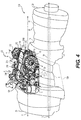
FIG. 4 , another exemplary transversemounted AGB 200 is shown. As the transversemounted AGB 200 may be mounted on any suitable gas turbine engine, such as the HPW3000 gas turbine engine produced by Advanced Turbine Engine Company (ATEC) discussed with regard toFigs. 2-3 , the same reference numerals used to denote the same or substantially similar components. InFig. 4 , the transverse mountedAGB 200 is coupled to thegas turbine engine 100. Thegas turbine engine 100 includes theengine casing 50, theair intake bellmouth 25, thecompressor 5, thecombustion section 10, theexhaust turbine 15, theexhaust plenum 20 and thetransverse AGB 200. As will be discussed herein, thetransverse AGB 200 drives various accessories, such as the inletparticle accelerator fan 115, theoil pump 125, theair oil separator 130, theair turbine starter 135, afuel metering unit 206 and apermanent magnet alternator 208. As the accessories driven by thetransverse AGB 200 are generally known in the art, the accessories will not be discussed in detail herein. - The
AGB 200 includes ahousing 201 and agear train assembly 204. Thehousing 201 is coupled to thegas turbine engine 100. As illustrated inFIG. 4 , thehousing 201 is coupled to the waist of thegas turbine engine 100. Thehousing 201 of theAGB 200 extends along an axis A. The axis A is substantially parallel to a longitudinal axis L of thegas turbine engine 100 and is substantially parallel to the rotational axis of thedrive shaft 30 of thegas turbine engine 100. Thehousing 201 substantially encases or contains thegear train assembly 204 associated with theAGB 200. In one example, with reference toFIG. 5 , thehousing 201 comprises agear case 210 and acover 212. Thecover 212 is coupled to afirst side 210a of thegear case 210, which is opposite asecond side 210b of thegear case 210. Thecover 212 includes a plurality of bores 212a, which are sized and configured to receive a suitable fastener, such as amechanical fastener 212b, to couple thecover 212 to thegear case 210. Thecover 212 may also define one ormore apertures 212c for receipt of portions of thegear train assembly 204. - With reference to
FIG. 6 , thegear case 210 supports and encloses portions of thegear train assembly 204. Generally, thegear case 210 and thecover 212 support one or more bearings associated with thegear train assembly 204, and the bearings support one or more shafts associated with thegear train assembly 204, with the one or more shafts supporting a remainder of thegear train assembly 204. In this example, thegear case 210 includes afirst portion 214, asecond portion 216 and athird portion 218. Thefirst portion 214 defines acylindrical shaft 220. Thecylindrical shaft 220 is defined within thefirst portion 214 so as to be substantially centered within acavity 222 defined by thefirst portion 214. Thecylindrical shaft 220 receives a portion of thegear train assembly 204. Thepermanent magnet alternator 208 is also received within thecylindrical shaft 220. Thecavity 222 is sized and shaped to receive a portion of the inlet particle accelerator fan 115 (FIG. 4 ). With reference toFIG. 4 , thefirst portion 214 is coupled to the inletparticle accelerator fan 115, which in turn is coupled to asuitable duct 224. - The
second portion 216 of thegear case 210 receives a portion of thegear train assembly 204. Thesecond portion 216 also receives theair oil separator 130. Thesecond portion 216 is substantially cylindrical; however, thesecond portion 216 may have any desired shape. Thesecond portion 216 is arranged between thefirst portion 214 and thethird portion 218. Thethird portion 218 receives a portion of thegear train assembly 204. Thethird portion 218 is substantially cylindrical, and is coupled to thefuel metering unit 206 at a first end and theoil pump 125 at a second end. - With reference to
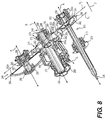
FIG. 7 , thegear train assembly 204 is shown coupled to the tower shaft 35'. InFIG. 7 , thegear train assembly 204 is illustrated without thehousing 201 for simplicity and to aid in understanding. It should be understood that when assembled, thehousing 201 encloses a portion of thegear train assembly 204 and is configured to enable a portion of thegear train assembly 204 to meshingly engage with the tower shaft 35' as illustrated inFIG. 4 . Thegear train assembly 204 includes afirst gear 240, asecond gear 242, a third gear 244 (FIG. 8 ) and afourth gear 246. With reference toFIG. 8 , each of thefirst gear 240, thesecond gear 242, thethird gear 244 and thefourth gear 246 rotate about a respective rotational axis R, which is also generally a centerline for each of thefirst gear 240, thesecond gear 242, thethird gear 244 and thefourth gear 246. Each rotational axis R is transverse to a longitudinal axis TL of the tower shaft 35'. In one example, each rotational axis R is substantially perpendicular to the longitudinal axis TL of the tower shaft 35'. Each rotational axis R is also substantially perpendicular to the longitudinal axis L of thegas turbine engine 100. Each rotational axis R is also substantially perpendicular is also substantially perpendicular to thedrive shaft 30 and to the rotational axis of thedrive shaft 30 of thegas turbine engine 100. Moreover, the rotational axes of all of the accessories (not shown) driven by thetransverse AGB 200 are also perpendicular to thedrive shaft 30 and to the rotational axis of thedrive shaft 30. For clarity, the various teeth associated with each of thefirst gear 240, thesecond gear 242, thethird gear 244 and thefourth gear 246 are not illustrated herein, with the understanding that the various engagement surfaces of thefirst gear 240, thesecond gear 242, thethird gear 244 and thefourth gear 246 described herein below each include a plurality of gear teeth according to various embodiments. - As best illustrated in
FIG. 8 , thethird gear 244 and thesecond gear 242 extend along a first axis A1 within thehousing 201, and thefirst gear 240 and thefourth gear 246 extend along a second axis A2 within thehousing 201. The first axis A1 and the second axis A2 are each substantially perpendicular to the rotational axes R and substantially parallel to the axis A of thehousing 201. The first axis A1 and the second axis A2 are also spaced apart from or offset from each other. - With reference to
FIG. 8 , thefirst gear 240 and thesecond gear 242 are coupled to or mounted on afirst shaft 248. Thefirst gear 240 is generally formed of a metal or metal alloy through a suitable manufacturing technique, such as casting, machining, etc., and is coupled to thefirst shaft 248 through a suitable technique such as welding, press-fit, etc. Thefirst gear 240 includes ahub 250, afirst engagement surface 252 and asecond engagement surface 254. Thehub 250 includes apost 256, which defines anopening 258. Theopening 258 receives a portion of thefirst shaft 248 to couple thefirst gear 240 to thefirst shaft 248. Generally, theopening 258 is sized such that thefirst gear 240 is pressed onto thefirst shaft 248 such that rotation of thefirst gear 240 causes the rotation of thefirst shaft 248. Thepost 256 is sized to be positioned adjacent to thesecond gear 242 when thefirst gear 240 is coupled to thefirst shaft 248. - The
first engagement surface 252 is defined at a periphery of thehub 250 and extends substantially about aperimeter 250a or circumference of thehub 250. Thefirst engagement surface 252 is coupled to and engages with thethird gear 244 to drive thethird gear 244. In one example, thefirst engagement surface 252 comprises a first plurality of teeth, which are spaced apart theperimeter 250a of thehub 250 to meshingly engage with and drive thethird gear 244. In this example, thefirst engagement surface 252 comprises about 78 gear teeth, which have a diametral pitch of about 16. Generally, thefirst engagement surface 252 drives thethird gear 244 in a counterclockwise direction when viewed along a direction D. - The
second engagement surface 254 is defined adjacent to the periphery of thehub 250 and extends substantially about theperimeter 250a of thehub 250 along afirst side 250b of thehub 250. Generally, thesecond engagement surface 254 extends only along thefirst side 250b of thehub 250, and is spaced apart from thefirst engagement surface 252. Thesecond engagement surface 254 is coupled to and engages with the tower shaft 35' to enable the tower shaft 35' to drive thefirst gear 240. In one example, thesecond engagement surface 254 comprises a plurality of beveled teeth, which are spaced apart along theside 250b of thehub 250 to meshingly engage with thebevel gear 43 of the tower shaft 35' (FIG. 7 ). In this example, thesecond engagement surface 254 comprises about 88 beveled gear teeth, which have a diametral pitch of about 20. Generally, thesecond engagement surface 254 is driven by thebevel gear 43 of the tower shaft 35' in a clockwise direction when viewed along the direction D. - The
second gear 242 is composed of a metal or metal alloy and is generally formed about thefirst shaft 248 through a suitable forming technique, such as casting, etc., however; it should be understood that thesecond gear 242 may be formed separately from thefirst shaft 248 and coupled to thefirst shaft 248 via a suitable technique, such as welding, press-fit, etc. Thesecond gear 242 has a diameter that is smaller than or less than a diameter of thefirst gear 240. Thesecond gear 242 includes ahub 260 and athird engagement surface 262. Thehub 260 extends outwardly from thefirst shaft 248. Thethird engagement surface 262 is defined at a periphery of thehub 260 and extends substantially about aperimeter 260a or circumference of thehub 260. Thethird engagement surface 262 is coupled to and engages with thethird gear 244 to drive thethird gear 244. In one example, thethird engagement surface 262 comprises a second plurality of teeth, which are spaced apart along theperimeter 260a of thehub 260 to meshingly engage with and drive thethird gear 244. In this example, thethird engagement surface 262 comprises about 52 gear teeth, which have a diametral pitch of about 20. Generally, thethird engagement surface 262 drives thethird gear 244 in a counterclockwise direction when viewed along the direction D. - The
first shaft 248 is rotatable by the tower shaft 35' via thefirst gear 240 and the bevel gear 43 (FIG. 7 ). Thefirst shaft 248 has afirst end 264 and a second end 266. Thefirst end 264 is coupled to theair oil separator 130 and is coupled to abreather vent 268. Theair oil separator 130 is coupled to thefirst shaft 248 such that the rotation of thefirst shaft 248 drives theair oil separator 130. Abearing 270 is coupled to thefirst shaft 248 between theair oil separator 130 and thebreather vent 268 to assist in the rotation of thefirst shaft 248. Thebearing 270 may comprise any suitable bearing, including, but not limited to, a ball bearing. - The second end 266 includes a
bearing 272 and acollar 274. Thebearing 272 is coupled to thefirst shaft 248 to assist with the rotation of thefirst shaft 248. Thebearing 272 is generally coupled to thefirst shaft 248 to be positioned between thefirst gear 240 and thecollar 274. Thebearing 272 may comprise any suitable bearing, including, but not limited to, a ball bearing. Thecollar 274 assists in retaining the bearing 272 on thefirst shaft 248. - The
third gear 244 is generally formed of a metal or metal alloy through a suitable manufacturing technique, such as casting, machining, etc., and is coupled to asecond shaft 280 through a suitable technique such as welding, press-fit, etc. In one example, thethird gear 244 is formed about thesecond shaft 280, however; it should be understood that thethird gear 244 may be formed separately from thesecond shaft 280 and coupled to thesecond shaft 280 via a suitable technique, such as welding, press-fit, etc. Thethird gear 244 has a diameter that is greater than the diameter of thefirst gear 240 and the diameter of thesecond gear 242. Thethird gear 244 includes ahub 282 and afourth engagement surface 284. - The
hub 282 extends outwardly from thesecond shaft 280. Thefourth engagement surface 284 is defined at a periphery of thehub 282 and extends substantially about aperimeter 282a or circumference of thehub 250. Thefourth engagement surface 284 is coupled to and engages with thethird engagement surface 262 of thesecond gear 242 to be driven by thesecond gear 242. In one example, thefourth engagement surface 284 comprises a third plurality of teeth, which are spaced apart theperimeter 282a of thehub 282 to meshingly engage with thethird engagement surface 262 of thethird gear 244. In this example, thefourth engagement surface 284 comprises about 107 gear teeth, which have a diametral pitch of about 20. Generally, thefourth engagement surface 284 is driven by thesecond gear 242 in a counterclockwise direction when viewed along the direction D. - The
second shaft 280 has a length, which is less than a length of thefirst shaft 248. Thesecond shaft 280 includes afirst end 286 and asecond end 288. Thethird gear 244 is generally formed about thesecond shaft 280 between thefirst end 286 and thesecond end 288. Thefirst end 286 is coupled to theoil pump 125, and includes abearing 290 to assist in the rotation of thesecond shaft 280. Thebearing 290 may comprise any suitable bearing, including, but not limited to, a ball bearing. Thesecond end 288 is coupled to thefuel metering unit 206, and includes abearing 292 to assist in the rotation of thesecond shaft 280. Thebearing 292 may comprise any suitable bearing, including, but not limited to, a ball bearing. - The
fourth gear 246 is coupled to or mounted on athird shaft 300. Thefourth gear 246 is generally formed of a metal or metal alloy through a suitable manufacturing technique, such as casting, machining, etc., and is coupled to thethird shaft 300 through a suitable technique such as welding, press-fit, etc. In one example, thefourth gear 246 is formed about thethird shaft 300, however; it should be understood that thefourth gear 246 may be formed separately from thethird shaft 300 and coupled to thethird shaft 300 via a suitable technique, such as welding, press-fit, etc. Thefourth gear 246 has a diameter that is less than the diameter of thefirst gear 240 and the diameter of thethird gear 244, but is greater than the diameter of thesecond gear 242. Thefourth gear 246 includes ahub 302 and afifth engagement surface 304. - The
hub 302 extends outwardly from thethird shaft 300. Thefifth engagement surface 304 is defined at a periphery of thehub 302 and extends substantially about aperimeter 302a or circumference of thehub 302. Thefifth engagement surface 304 is coupled to and engages with thefirst engagement surface 252 of thefirst gear 240 to be driven by thefirst gear 240. In one example, thefifth engagement surface 304 comprises a fifth plurality of teeth, which are spaced apart theperimeter 302a of thehub 302 to meshingly engage with thefirst engagement surface 252 of thefirst gear 240. In this example, thefifth engagement surface 304 comprises about 46 teeth, which have a diametral pitch of about 16. Generally, thefifth engagement surface 304 is driven by thefirst gear 240 in a counterclockwise direction when viewed along the direction D. - The
third shaft 300 has a length, which is greater than the length of thefirst shaft 248 and the length of thesecond shaft 280. Thethird shaft 300 includes afirst end 306 and asecond end 308. Thefourth gear 246 is generally formed about thethird shaft 300 near thesecond end 308. Thefirst end 306 is coupled to the inlet particle accelerator fan 115 (FIG. 4 ). Thepermanent magnet alternator 208 is coupled to thethird shaft 300 between thefirst end 306 and thesecond end 308. Generally, thepermanent magnet alternator 208 is coupled to thethird shaft 300 to rotate with thethird shaft 300. Abearing 310 is coupled adjacent to thepermanent magnet alternator 208 to assist in the rotation of thethird shaft 300. Thebearing 310 may comprise any suitable bearing, including, but not limited to, a ball bearing. Thesecond end 308 is coupled to theair turbine starter 135, and includes abearing 312 to assist in the rotation of thethird shaft 300. Thebearing 312 may comprise any suitable bearing, including, but not limited to, a ball bearing. - In order to assemble the
transverse AGB 200, in one example, thethird shaft 300 is coupled to thegear case 210 with thefourth gear 246 formed thereon. Thebearing 310 and thepermanent magnet alternator 208 are coupled to thethird shaft 300 near thefirst end 306, and thebearing 312 is coupled to thesecond end 308. Thefirst shaft 248 is coupled to thegear case 210, and thefirst gear 240 is pressed onto thefirst shaft 248. Thebearing 272 and thecollar 274 are coupled to the second end 266 of thefirst shaft 248. Theair oil separator 130 is coupled adjacent to thesecond gear 242, and thebearing 270 is coupled adjacent to theair oil separator 130. Thebreather vent 268 is coupled to thefirst end 264 of thefirst shaft 248. Thesecond shaft 280 is coupled to thegear case 210, with thethird gear 244 formed thereon. Thebearing 290 is coupled to thefirst end 286, and thebearing 292 is coupled to thesecond end 288. With thegear train assembly 204 coupled to thegear case 210, thecover 212 is coupled to thegear case 210 via themechanical fasteners 212b to surround thesecond end 308 of thethird shaft 300, the second end 266 of thefirst shaft 248 and thesecond end 288 of the second shaft 280 (FIG. 5 ). - When in use, the
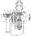
drive shaft 30 drives the tower shaft 35'. Thebevel gear 43 of the tower shaft 35' meshingly engages thesecond engagement surface 254 of thefirst gear 240 to drive the first gear 240 (FIG. 7 ). With reference toFIG. 9 , the rotation of thefirst gear 240 rotates thefirst shaft 248, which drives theair oil separator 130. As thefirst engagement surface 252 of thefirst gear 240 meshingly engages with thefifth engagement surface 304 of thefourth gear 246, the rotation of thefirst gear 240 rotates thefourth gear 246. The rotation of thefourth gear 246 drives thepermanent magnet alternator 208, the inletparticle accelerator fan 115 and theair turbine starter 135. - Further, as the
third engagement surface 262 of thesecond gear 242 meshingly engages with thefifth engagement surface 304 of thethird gear 244, the rotation of thefirst shaft 248 rotates thethird gear 244. The rotation of thethird gear 244 rotates thesecond shaft 280. The rotation of thesecond shaft 280 drives theoil pump 125 and thefuel metering unit 206. Thus, thetransverse AGB 200 drives various accessories of thegas turbine engine 100 with a compactgear train assembly 204 that is arranged in ahousing 201, which extends along an axis substantially parallel to the rotational axis of thedrive shaft 30 of thegas turbine engine 100. - While at least one exemplary embodiment has been presented in the foregoing detailed description of the invention, it should be appreciated that a vast number of variations exist. It should also be appreciated that the exemplary embodiment or exemplary embodiments are only examples, and are not intended to limit the scope, applicability, or configuration of the invention in any way. Rather, the foregoing detailed description will provide those skilled in the art with a convenient road map for implementing an exemplary embodiment of the invention. It being understood that various changes may be made in the function and arrangement of elements described in an exemplary embodiment without departing from the scope of the invention as set forth in the appended claims.
Claims (15)
- An accessory gear box for a gas turbine engine having a drive shaft with a rotational axis and a tower shaft coupled to the drive shaft, the accessory gear box comprising:a first plurality of gears arranged within the accessory gear box, the first plurality of gears extending along a first axis substantially parallel to the rotational axis of the drive shaft;a second plurality of gears arranged within the accessory gear box, the second plurality of gears extending along a second axis, the second axis offset from and substantially parallel to the first axis; anda first shaft, with one of the first plurality of gears coupled to the first shaft, and one of the second plurality of gears coupled to a second shaft,wherein the one of the second plurality of gears coupled to the first shaft includes a first engagement surface and a second engagement surface, the first engagement surface to engage the tower shaft and the second engagement surface is coupled to another one of the second plurality of gears to drive the second shaft.
- The accessory gear box of Claim 1, wherein the one of the first plurality of gears coupled to the first shaft is coupled to another one of the first plurality of gears to drive a third shaft.
- The accessory gear box of Claim 1, wherein each of the first plurality of gears include a rotational axis, and the rotational axis of each of the first plurality of gears is transverse to a longitudinal axis of the tower shaft.
- The accessory gear box of Claim 1, further comprising a housing that extends along a longitudinal axis, and the longitudinal axis of the housing is substantially parallel to the rotational axis of the drive shaft.
- The accessory gear box of Claim 1, wherein the first engagement surface is defined along a surface of the one of the second plurality of gears near a periphery of the one of the second plurality of gears.
- The accessory gear box of Claim 5, wherein the second engagement surface is defined at the periphery of the one of the second plurality of gears.
- The accessory gear box of Claim 1, wherein the first plurality of gears are arranged in a first row, and the second plurality of gears are arranged in a second row, the first row and the second row comprising the only gears arranged within the accessory gear box.
- A gas turbine engine, comprising:a drive shaft having a rotational axis;a tower shaft having a first end coupled to the drive shaft, and a second end including a bevel gear, the tower shaft having a longitudinal axis transverse to the rotational axis of the drive shaft; andthe accessory gear box of Claim 1.
- The gas turbine engine of Claim 8, wherein the second engagement surface is coupled to a third engagement surface of another of the second plurality of gears to drive the second shaft.
- The gas turbine engine of Claim 8, wherein the one of the first plurality of gears includes a fourth engagement surface, which is coupled to a fifth engagement surface of another one of the first plurality of gears to drive a third shaft.
- The gas turbine engine of Claim 8, wherein the first plurality of gears are arranged in a first row, and the second plurality of gears are arranged in a second row, the first row and the second row comprising the only gears arranged within the accessory gear box.
- The gas turbine engine of Claim 8, wherein the first engagement surface is defined along a surface of the one of the second plurality of gears near a periphery of the one of the second plurality of gears and the second engagement surface is defined at the periphery to extend about a perimeter of the one of the second plurality of gears.
- The gas turbine engine of Claim 9, wherein the second shaft drives an inlet particle accelerator fan, a permanent magnet alternator and an air turbine starter.
- The gas turbine engine of Claim 8, wherein the first shaft drives an air oil separator.
- The gas turbine engine of Claim 10, wherein the third shaft drives an oil pump and a fuel metering unit.
Applications Claiming Priority (1)
| Application Number | Priority Date | Filing Date | Title |
|---|---|---|---|
| US14/836,484 US9926849B2 (en) | 2011-06-14 | 2015-08-26 | Transverse mounted accessory gearbox |
Publications (2)
| Publication Number | Publication Date |
|---|---|
| EP3135882A1 true EP3135882A1 (en) | 2017-03-01 |
| EP3135882B1 EP3135882B1 (en) | 2020-04-15 |
Family
ID=56567360
Family Applications (1)
| Application Number | Title | Priority Date | Filing Date |
|---|---|---|---|
| EP16174673.0A Active EP3135882B1 (en) | 2015-08-26 | 2016-06-15 | Transverse mounted accessory gearbox |
Country Status (1)
| Country | Link |
|---|---|
| EP (1) | EP3135882B1 (en) |
Cited By (7)
| Publication number | Priority date | Publication date | Assignee | Title |
|---|---|---|---|---|
| US9752500B2 (en) | 2013-03-14 | 2017-09-05 | Pratt & Whitney Canada Corp. | Gas turbine engine with transmission and method of adjusting rotational speed |
| US10519871B2 (en) | 2017-05-18 | 2019-12-31 | Pratt & Whitney Canada Corp. | Support assembly for a propeller shaft |
| US10738709B2 (en) | 2017-02-09 | 2020-08-11 | Pratt & Whitney Canada Corp. | Multi-spool gas turbine engine |
| US10815899B2 (en) | 2016-11-15 | 2020-10-27 | Pratt & Whitney Canada Corp. | Gas turbine engine accessories arrangement |
| US10823081B2 (en) | 2017-12-21 | 2020-11-03 | Raytheon Technologies Corporation | Concentric power takeoff transmission |
| US11174916B2 (en) | 2019-03-21 | 2021-11-16 | Pratt & Whitney Canada Corp. | Aircraft engine reduction gearbox |
| US11268453B1 (en) | 2021-03-17 | 2022-03-08 | Pratt & Whitney Canada Corp. | Lubrication system for aircraft engine reduction gearbox |
Families Citing this family (1)
| Publication number | Priority date | Publication date | Assignee | Title |
|---|---|---|---|---|
| US11174782B2 (en) | 2017-02-10 | 2021-11-16 | Pratt & Whitney Canada Corp. | Planetary gearbox for gas turbine engine |
Citations (5)
| Publication number | Priority date | Publication date | Assignee | Title |
|---|---|---|---|---|
| GB1103417A (en) * | 1965-12-07 | 1968-02-14 | Dowty Rotol Ltd | Engine installations and starting means therefor |
| US20090232640A1 (en) * | 2008-03-14 | 2009-09-17 | Hispano Suiza | Assembly for driving gas turbine accessories |
| EP2535544A2 (en) * | 2011-06-14 | 2012-12-19 | Honeywell International, Inc. | Transverse mounted accessory gearbox |
| WO2014195632A1 (en) * | 2013-06-06 | 2014-12-11 | Snecma | Accessory drive case for a turboprop |
| FR3017658A1 (en) * | 2014-02-18 | 2015-08-21 | Hispano Suiza Sa | EQUIPMENT DRIVE HOUSING FOR TURBOMACHINE |
-
2016
- 2016-06-15 EP EP16174673.0A patent/EP3135882B1/en active Active
Patent Citations (5)
| Publication number | Priority date | Publication date | Assignee | Title |
|---|---|---|---|---|
| GB1103417A (en) * | 1965-12-07 | 1968-02-14 | Dowty Rotol Ltd | Engine installations and starting means therefor |
| US20090232640A1 (en) * | 2008-03-14 | 2009-09-17 | Hispano Suiza | Assembly for driving gas turbine accessories |
| EP2535544A2 (en) * | 2011-06-14 | 2012-12-19 | Honeywell International, Inc. | Transverse mounted accessory gearbox |
| WO2014195632A1 (en) * | 2013-06-06 | 2014-12-11 | Snecma | Accessory drive case for a turboprop |
| FR3017658A1 (en) * | 2014-02-18 | 2015-08-21 | Hispano Suiza Sa | EQUIPMENT DRIVE HOUSING FOR TURBOMACHINE |
Cited By (7)
| Publication number | Priority date | Publication date | Assignee | Title |
|---|---|---|---|---|
| US9752500B2 (en) | 2013-03-14 | 2017-09-05 | Pratt & Whitney Canada Corp. | Gas turbine engine with transmission and method of adjusting rotational speed |
| US10815899B2 (en) | 2016-11-15 | 2020-10-27 | Pratt & Whitney Canada Corp. | Gas turbine engine accessories arrangement |
| US10738709B2 (en) | 2017-02-09 | 2020-08-11 | Pratt & Whitney Canada Corp. | Multi-spool gas turbine engine |
| US10519871B2 (en) | 2017-05-18 | 2019-12-31 | Pratt & Whitney Canada Corp. | Support assembly for a propeller shaft |
| US10823081B2 (en) | 2017-12-21 | 2020-11-03 | Raytheon Technologies Corporation | Concentric power takeoff transmission |
| US11174916B2 (en) | 2019-03-21 | 2021-11-16 | Pratt & Whitney Canada Corp. | Aircraft engine reduction gearbox |
| US11268453B1 (en) | 2021-03-17 | 2022-03-08 | Pratt & Whitney Canada Corp. | Lubrication system for aircraft engine reduction gearbox |
Also Published As
| Publication number | Publication date |
|---|---|
| EP3135882B1 (en) | 2020-04-15 |
Similar Documents
| Publication | Publication Date | Title |
|---|---|---|
| US9926849B2 (en) | Transverse mounted accessory gearbox | |
| EP2535544B1 (en) | Transverse mounted accessory gearbox | |
| EP3135882B1 (en) | Transverse mounted accessory gearbox | |
| US7351174B2 (en) | Twin turbo-shaft engine with accessory gearbox drive means | |
| US11585354B2 (en) | Engine having variable pitch outlet guide vanes | |
| US8966911B2 (en) | Turbofan engine with HP and LP power off-takes | |
| EP2085589B1 (en) | Gas turbine engine comprising an accessory gearbox | |
| US10197150B2 (en) | Gear baffle configured with lubricant outlet passage | |
| US8192143B2 (en) | Gearbox assembly | |
| US10364752B2 (en) | System and method for an integral drive engine with a forward main gearbox | |
| US11591971B2 (en) | Hybrid transmission on propeller gearbox | |
| EP2939929A1 (en) | Multi-axis accessory gearboxes of mechanical drive systems and gas turbine engines including the same | |
| EP3786428A1 (en) | Oil tank for geared turbofan engine | |
| EP3957841A1 (en) | Air turbine starter | |
| CN111322157B (en) | Planet carrier and method of assembling a planet carrier | |
| US11448134B2 (en) | Equipment drive gearbox in a turbomachine | |
| US10415622B2 (en) | Method and system for hybrid gang channel bolted joint | |
| US10995675B2 (en) | Gas turbine engine with accessory gearbox | |
| US20230366325A1 (en) | Turbomachine module provided with a propeller and offset stator vanes | |
| US20230340907A1 (en) | Engine controller for a gas turbine engine | |
| EP3940213A1 (en) | Air starter with offset interface |
Legal Events
| Date | Code | Title | Description |
|---|---|---|---|
| PUAI | Public reference made under article 153(3) epc to a published international application that has entered the european phase |
Free format text: ORIGINAL CODE: 0009012 |
|
| STAA | Information on the status of an ep patent application or granted ep patent |
Free format text: STATUS: REQUEST FOR EXAMINATION WAS MADE |
|
| 17P | Request for examination filed |
Effective date: 20160615 |
|
| AK | Designated contracting states |
Kind code of ref document: A1 Designated state(s): AL AT BE BG CH CY CZ DE DK EE ES FI FR GB GR HR HU IE IS IT LI LT LU LV MC MK MT NL NO PL PT RO RS SE SI SK SM TR |
|
| AX | Request for extension of the european patent |
Extension state: BA ME |
|
| STAA | Information on the status of an ep patent application or granted ep patent |
Free format text: STATUS: EXAMINATION IS IN PROGRESS |
|
| 17Q | First examination report despatched |
Effective date: 20190703 |
|
| GRAP | Despatch of communication of intention to grant a patent |
Free format text: ORIGINAL CODE: EPIDOSNIGR1 |
|
| STAA | Information on the status of an ep patent application or granted ep patent |
Free format text: STATUS: GRANT OF PATENT IS INTENDED |
|
| INTG | Intention to grant announced |
Effective date: 20191212 |
|
| GRAS | Grant fee paid |
Free format text: ORIGINAL CODE: EPIDOSNIGR3 |
|
| GRAA | (expected) grant |
Free format text: ORIGINAL CODE: 0009210 |
|
| STAA | Information on the status of an ep patent application or granted ep patent |
Free format text: STATUS: THE PATENT HAS BEEN GRANTED |
|
| AK | Designated contracting states |
Kind code of ref document: B1 Designated state(s): AL AT BE BG CH CY CZ DE DK EE ES FI FR GB GR HR HU IE IS IT LI LT LU LV MC MK MT NL NO PL PT RO RS SE SI SK SM TR |
|
| REG | Reference to a national code |
Ref country code: CH Ref legal event code: EP |
|
| REG | Reference to a national code |
Ref country code: DE Ref legal event code: R096 Ref document number: 602016033921 Country of ref document: DE |
|
| REG | Reference to a national code |
Ref country code: IE Ref legal event code: FG4D |
|
| REG | Reference to a national code |
Ref country code: AT Ref legal event code: REF Ref document number: 1257561 Country of ref document: AT Kind code of ref document: T Effective date: 20200515 |
|
| REG | Reference to a national code |
Ref country code: NL Ref legal event code: MP Effective date: 20200415 |
|
| REG | Reference to a national code |
Ref country code: LT Ref legal event code: MG4D |
|
| PG25 | Lapsed in a contracting state [announced via postgrant information from national office to epo] |
Ref country code: PT Free format text: LAPSE BECAUSE OF FAILURE TO SUBMIT A TRANSLATION OF THE DESCRIPTION OR TO PAY THE FEE WITHIN THE PRESCRIBED TIME-LIMIT Effective date: 20200817 Ref country code: LT Free format text: LAPSE BECAUSE OF FAILURE TO SUBMIT A TRANSLATION OF THE DESCRIPTION OR TO PAY THE FEE WITHIN THE PRESCRIBED TIME-LIMIT Effective date: 20200415 Ref country code: GR Free format text: LAPSE BECAUSE OF FAILURE TO SUBMIT A TRANSLATION OF THE DESCRIPTION OR TO PAY THE FEE WITHIN THE PRESCRIBED TIME-LIMIT Effective date: 20200716 Ref country code: FI Free format text: LAPSE BECAUSE OF FAILURE TO SUBMIT A TRANSLATION OF THE DESCRIPTION OR TO PAY THE FEE WITHIN THE PRESCRIBED TIME-LIMIT Effective date: 20200415 Ref country code: NO Free format text: LAPSE BECAUSE OF FAILURE TO SUBMIT A TRANSLATION OF THE DESCRIPTION OR TO PAY THE FEE WITHIN THE PRESCRIBED TIME-LIMIT Effective date: 20200715 Ref country code: NL Free format text: LAPSE BECAUSE OF FAILURE TO SUBMIT A TRANSLATION OF THE DESCRIPTION OR TO PAY THE FEE WITHIN THE PRESCRIBED TIME-LIMIT Effective date: 20200415 Ref country code: SE Free format text: LAPSE BECAUSE OF FAILURE TO SUBMIT A TRANSLATION OF THE DESCRIPTION OR TO PAY THE FEE WITHIN THE PRESCRIBED TIME-LIMIT Effective date: 20200415 Ref country code: IS Free format text: LAPSE BECAUSE OF FAILURE TO SUBMIT A TRANSLATION OF THE DESCRIPTION OR TO PAY THE FEE WITHIN THE PRESCRIBED TIME-LIMIT Effective date: 20200815 |
|
| REG | Reference to a national code |
Ref country code: AT Ref legal event code: MK05 Ref document number: 1257561 Country of ref document: AT Kind code of ref document: T Effective date: 20200415 |
|
| PG25 | Lapsed in a contracting state [announced via postgrant information from national office to epo] |
Ref country code: HR Free format text: LAPSE BECAUSE OF FAILURE TO SUBMIT A TRANSLATION OF THE DESCRIPTION OR TO PAY THE FEE WITHIN THE PRESCRIBED TIME-LIMIT Effective date: 20200415 Ref country code: RS Free format text: LAPSE BECAUSE OF FAILURE TO SUBMIT A TRANSLATION OF THE DESCRIPTION OR TO PAY THE FEE WITHIN THE PRESCRIBED TIME-LIMIT Effective date: 20200415 Ref country code: LV Free format text: LAPSE BECAUSE OF FAILURE TO SUBMIT A TRANSLATION OF THE DESCRIPTION OR TO PAY THE FEE WITHIN THE PRESCRIBED TIME-LIMIT Effective date: 20200415 Ref country code: BG Free format text: LAPSE BECAUSE OF FAILURE TO SUBMIT A TRANSLATION OF THE DESCRIPTION OR TO PAY THE FEE WITHIN THE PRESCRIBED TIME-LIMIT Effective date: 20200715 |
|
| PG25 | Lapsed in a contracting state [announced via postgrant information from national office to epo] |
Ref country code: AL Free format text: LAPSE BECAUSE OF FAILURE TO SUBMIT A TRANSLATION OF THE DESCRIPTION OR TO PAY THE FEE WITHIN THE PRESCRIBED TIME-LIMIT Effective date: 20200415 |
|
| REG | Reference to a national code |
Ref country code: DE Ref legal event code: R097 Ref document number: 602016033921 Country of ref document: DE |
|
| PG25 | Lapsed in a contracting state [announced via postgrant information from national office to epo] |
Ref country code: MC Free format text: LAPSE BECAUSE OF FAILURE TO SUBMIT A TRANSLATION OF THE DESCRIPTION OR TO PAY THE FEE WITHIN THE PRESCRIBED TIME-LIMIT Effective date: 20200415 Ref country code: ES Free format text: LAPSE BECAUSE OF FAILURE TO SUBMIT A TRANSLATION OF THE DESCRIPTION OR TO PAY THE FEE WITHIN THE PRESCRIBED TIME-LIMIT Effective date: 20200415 Ref country code: CZ Free format text: LAPSE BECAUSE OF FAILURE TO SUBMIT A TRANSLATION OF THE DESCRIPTION OR TO PAY THE FEE WITHIN THE PRESCRIBED TIME-LIMIT Effective date: 20200415 Ref country code: SM Free format text: LAPSE BECAUSE OF FAILURE TO SUBMIT A TRANSLATION OF THE DESCRIPTION OR TO PAY THE FEE WITHIN THE PRESCRIBED TIME-LIMIT Effective date: 20200415 Ref country code: IT Free format text: LAPSE BECAUSE OF FAILURE TO SUBMIT A TRANSLATION OF THE DESCRIPTION OR TO PAY THE FEE WITHIN THE PRESCRIBED TIME-LIMIT Effective date: 20200415 Ref country code: RO Free format text: LAPSE BECAUSE OF FAILURE TO SUBMIT A TRANSLATION OF THE DESCRIPTION OR TO PAY THE FEE WITHIN THE PRESCRIBED TIME-LIMIT Effective date: 20200415 Ref country code: DK Free format text: LAPSE BECAUSE OF FAILURE TO SUBMIT A TRANSLATION OF THE DESCRIPTION OR TO PAY THE FEE WITHIN THE PRESCRIBED TIME-LIMIT Effective date: 20200415 Ref country code: EE Free format text: LAPSE BECAUSE OF FAILURE TO SUBMIT A TRANSLATION OF THE DESCRIPTION OR TO PAY THE FEE WITHIN THE PRESCRIBED TIME-LIMIT Effective date: 20200415 Ref country code: AT Free format text: LAPSE BECAUSE OF FAILURE TO SUBMIT A TRANSLATION OF THE DESCRIPTION OR TO PAY THE FEE WITHIN THE PRESCRIBED TIME-LIMIT Effective date: 20200415 |
|
| REG | Reference to a national code |
Ref country code: CH Ref legal event code: PL |
|
| PLBE | No opposition filed within time limit |
Free format text: ORIGINAL CODE: 0009261 |
|
| STAA | Information on the status of an ep patent application or granted ep patent |
Free format text: STATUS: NO OPPOSITION FILED WITHIN TIME LIMIT |
|
| PG25 | Lapsed in a contracting state [announced via postgrant information from national office to epo] |
Ref country code: PL Free format text: LAPSE BECAUSE OF FAILURE TO SUBMIT A TRANSLATION OF THE DESCRIPTION OR TO PAY THE FEE WITHIN THE PRESCRIBED TIME-LIMIT Effective date: 20200415 Ref country code: SK Free format text: LAPSE BECAUSE OF FAILURE TO SUBMIT A TRANSLATION OF THE DESCRIPTION OR TO PAY THE FEE WITHIN THE PRESCRIBED TIME-LIMIT Effective date: 20200415 |
|
| 26N | No opposition filed |
Effective date: 20210118 |
|
| GBPC | Gb: european patent ceased through non-payment of renewal fee |
Effective date: 20200715 |
|
| PG25 | Lapsed in a contracting state [announced via postgrant information from national office to epo] |
Ref country code: LU Free format text: LAPSE BECAUSE OF NON-PAYMENT OF DUE FEES Effective date: 20200615 |
|
| REG | Reference to a national code |
Ref country code: BE Ref legal event code: MM Effective date: 20200630 |
|
| PG25 | Lapsed in a contracting state [announced via postgrant information from national office to epo] |
Ref country code: IE Free format text: LAPSE BECAUSE OF NON-PAYMENT OF DUE FEES Effective date: 20200615 Ref country code: GB Free format text: LAPSE BECAUSE OF NON-PAYMENT OF DUE FEES Effective date: 20200715 Ref country code: FR Free format text: LAPSE BECAUSE OF NON-PAYMENT OF DUE FEES Effective date: 20200615 Ref country code: CH Free format text: LAPSE BECAUSE OF NON-PAYMENT OF DUE FEES Effective date: 20200630 Ref country code: LI Free format text: LAPSE BECAUSE OF NON-PAYMENT OF DUE FEES Effective date: 20200630 |
|
| PG25 | Lapsed in a contracting state [announced via postgrant information from national office to epo] |
Ref country code: BE Free format text: LAPSE BECAUSE OF NON-PAYMENT OF DUE FEES Effective date: 20200630 Ref country code: SI Free format text: LAPSE BECAUSE OF FAILURE TO SUBMIT A TRANSLATION OF THE DESCRIPTION OR TO PAY THE FEE WITHIN THE PRESCRIBED TIME-LIMIT Effective date: 20200415 |
|
| PG25 | Lapsed in a contracting state [announced via postgrant information from national office to epo] |
Ref country code: TR Free format text: LAPSE BECAUSE OF FAILURE TO SUBMIT A TRANSLATION OF THE DESCRIPTION OR TO PAY THE FEE WITHIN THE PRESCRIBED TIME-LIMIT Effective date: 20200415 Ref country code: MT Free format text: LAPSE BECAUSE OF FAILURE TO SUBMIT A TRANSLATION OF THE DESCRIPTION OR TO PAY THE FEE WITHIN THE PRESCRIBED TIME-LIMIT Effective date: 20200415 Ref country code: CY Free format text: LAPSE BECAUSE OF FAILURE TO SUBMIT A TRANSLATION OF THE DESCRIPTION OR TO PAY THE FEE WITHIN THE PRESCRIBED TIME-LIMIT Effective date: 20200415 |
|
| PG25 | Lapsed in a contracting state [announced via postgrant information from national office to epo] |
Ref country code: MK Free format text: LAPSE BECAUSE OF FAILURE TO SUBMIT A TRANSLATION OF THE DESCRIPTION OR TO PAY THE FEE WITHIN THE PRESCRIBED TIME-LIMIT Effective date: 20200415 |
|
| P01 | Opt-out of the competence of the unified patent court (upc) registered |
Effective date: 20230525 |
|
| PGFP | Annual fee paid to national office [announced via postgrant information from national office to epo] |
Ref country code: DE Payment date: 20230627 Year of fee payment: 8 |