EP4467765A1 - Bohrloch-radialkraftwerkzeuganordnung - Google Patents
Bohrloch-radialkraftwerkzeuganordnung Download PDFInfo
- Publication number
- EP4467765A1 EP4467765A1 EP23174932.6A EP23174932A EP4467765A1 EP 4467765 A1 EP4467765 A1 EP 4467765A1 EP 23174932 A EP23174932 A EP 23174932A EP 4467765 A1 EP4467765 A1 EP 4467765A1
- Authority
- EP
- European Patent Office
- Prior art keywords
- face
- arm member
- rear arm
- radial force
- tool assembly
- Prior art date
- Legal status (The legal status is an assumption and is not a legal conclusion. Google has not performed a legal analysis and makes no representation as to the accuracy of the status listed.)
- Withdrawn
Links
Images



Classifications
-
- E—FIXED CONSTRUCTIONS
- E21—EARTH OR ROCK DRILLING; MINING
- E21B—EARTH OR ROCK DRILLING; OBTAINING OIL, GAS, WATER, SOLUBLE OR MELTABLE MATERIALS OR A SLURRY OF MINERALS FROM WELLS
- E21B17/00—Drilling rods or pipes; Flexible drill strings; Kellies; Drill collars; Sucker rods; Cables; Casings; Tubings
- E21B17/10—Wear protectors; Centralising devices, e.g. stabilisers
- E21B17/1014—Flexible or expansible centering means, e.g. with pistons pressing against the wall of the well
- E21B17/1021—Flexible or expansible centering means, e.g. with pistons pressing against the wall of the well with articulated arms or arcuate springs
-
- E—FIXED CONSTRUCTIONS
- E21—EARTH OR ROCK DRILLING; MINING
- E21B—EARTH OR ROCK DRILLING; OBTAINING OIL, GAS, WATER, SOLUBLE OR MELTABLE MATERIALS OR A SLURRY OF MINERALS FROM WELLS
- E21B23/00—Apparatus for displacing, setting, locking, releasing or removing tools, packers or the like in boreholes or wells
- E21B23/01—Apparatus for displacing, setting, locking, releasing or removing tools, packers or the like in boreholes or wells for anchoring the tools or the like
Definitions
- Radial force generators are known in the hydrocarbon industry for anchoring a downhole tool in a well, e.g. for pulling or setting a plug, in order to transfer the axial force into a pulling or pushing force along the axial extension of the well tubular metal structure. Radial force generators may also be used for centralising a tool in the well for performing a certain operation needing centralising, such as logging or imaging.
- a radial force generator is known from US 6,920,936 , which has a very complex design where rollers on arms are arranged to support the projected arms when the arms are only slightly projected to overcome the problem of very limited force at small angles.
- such complicated design has many parts which may get stuck or worn out, and the known radial force generators still have a very limited radial extension.
- a radial force tool assembly for providing a radial force perpendicularly to an axial extension of the radial force tool assembly in a well for anchoring, centralising or rolling a downhole intervention tool in a well having a borehole, the radial force tool assembly having a centre axis, a front end and a rear end, and comprising:
- the first end face of the first rear arm member is enabled to roll and not slide on the first inclined face since the first rear arm member is projecting radially outwards in a first radial direction.
- the members are hingedly or "linkagely” connected, and this provides high friction causing wear in the connection. Furthermore, the force is translated almost entirely from the first force-transmitting member to the first and second rear members in an optimal manner.
- each of the first end faces may have a curvature following an involute of a circle, so that each first end face is shaped as the profile of half of a tooth of an involute gear.
- first rear arm member or the first cavity face may comprise a projection engaging a guide in the other of the first rear arm member and the first cavity face
- second rear arm member or the second cavity face may comprise a projection engaging a guide in the other of the second rear arm member and the second cavity face
- the radial force tool assembly may further comprise a first front arm member having a first end face and a second end face, and a second front arm member having a first end face and a second end face, the first front arm member or the first cavity face comprising a projection engaging a guide in the other of the first front arm member and the first cavity face, and the second front arm member or the second cavity face comprising a projection engaging a guide in the other of the second front arm member and the second cavity face.
- the first rear arm member may extend in a first diagonal direction between the first radial direction and the axial extension, and at a first angle to the axial extension.
- the second rear arm member when projecting, may extend in a second diagonal direction between the second radial direction and the axial extension, and at a second angle to the axial extension.
- the first front member when projecting, may extend in a third diagonal direction between the first radial direction and the axial extension, and at a third angle to the axial extension.
- the second front member when projecting, may extend in a fourth diagonal direction between the second radial direction and the axial extension, and at a fourth angle to the axial extension.
- first diagonal direction and the third diagonal direction may be parallel.
- the second diagonal direction and the fourth diagonal direction may be parallel.
- first angle, the second angle, the third angle and the fourth angle may be of equal size.
- the cavity may extend along the axial extension.
- first rear arm member may be slidably arranged in the cavity and may have a first arm centre axis extending along the axial extension at a first distance to the centre axis of the radial force tool assembly.
- the second rear arm member may be slidably arranged in the cavity and may have a second arm centre axis extending along the axial extension at a second distance to the centre axis of the radial force tool assembly, and the first distance may be equal to the second distance.
- first front arm member may be slidably arranged in the cavity and may have the first arm centre axis.
- the second front arm member may be slidably arranged in the cavity and may have the second arm centre axis.
- the radial force tool assembly may further comprise a first contact element and a second contact element, the first contact element being connected with the second end faces of the first rear arm member and the first front arm member, and the second contact element being connected with the second end faces of the second rear arm member and the second front arm member.
- first contact element may be connected with the second end faces of the first rear arm member and the first front arm member by means of another projection engaging a guide
- second contact element may be connected with the second end faces of the second rear arm member and the second front arm member by means of another projection engaging a guide
- the arm members may have a retracted position in which the arm members are arranged in the cavity, and the arm members may have a projected position in which the arm members project from the tool body.
- the force-transmitting member may have a projection sliding in a slot extending along the axial extension of the tool body.
- the invention also relates to a downhole intervention tool comprising the radial force tool assembly and a stroking tool
- the downhole intervention tool may further comprise an electric motor powered by a wireline and driving a pump supplying hydraulic fluid to the stroking tool for providing an axial force on an element by means of a hydraulic cylinder.
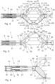
- Fig. 1 shows a radial force tool assembly 1 providing a radial force F perpendicularly to an axial extension 2 of the radial force tool assembly in a well 3 for anchoring the radial force tool assembly 1 and preventing at least axial movement along the axial extension 2.
- the radial force tool assembly 1 thus also centralises the radial force tool assembly 1 in a well tubular metal structure 3a in a borehole 3b.
- the radial force tool assembly 1 has a centre axis L, a front end 4 and a rear end 5, and comprises a tool body 6 comprising a cavity 7 having a longitudinal extension along the axial extension 2 of the tool assembly and extending across the tool body 6.
- the cavity 7 comprises a first cavity face 7a facing opposite a second cavity face 7b, so that the cavity has two side faces being the first cavity face and the second cavity face.
- the radial force tool assembly 1 further comprises a first actuator 8, 8a moving a first force-transmitting member 9, 9a in relation to the tool body 6 along the axial extension 2.
- the first force-transmitting member 9, 9a has a first end 10 with a first inclined face 11 and a second inclined face 12, the first and second inclined faces inclining in opposite directions.
- the radial force tool assembly 1 further comprises a first rear arm member 14, and as shown in Fig.
- Each of the first end faces has a curvature 23 following an involute of a circle, so that when the first force-transmitting member 9, 9a moves from its initial position towards the front end 4, the first end face 15 of the first rear arm member 14 rolls on the first inclined face 11, projecting the first rear arm member radially outwards in a first radial direction D1, and the first end face 18 of the second rear arm member 17 rolls on the second inclined face 12, projecting the second rear arm member radially outwards in a second radial direction D2 opposite the first radial direction, while the first and second rear arm members move from a retracted position to a projected position as shown in Figs. 1-7 and 10 .
- the curvature 23 shown in Fig. 4 is following an involute of a circle, which enables the first end face 15 of the first rear arm member 14 to roll and not slide on the first inclined face 11 as the first rear arm member is projecting radially outwards in the first radial direction D1.
- the first end face 15 of the second rear arm member 17 is enabled to roll and not slide on the second inclined face 12) while the first force-transmitting member 9, 9a moves from its initial position towards the front end 4.
- Each of the first end faces 15 has a curvature 23 following an involute of a circle, so that each first end face is shaped as the profile of half of a tooth of an involute gear.
- the first rear arm member 14 or the first cavity face 7a comprises a projection 21, 21a engaging a guide 22, 22a in the other of the first rear arm member and the first cavity face
- the second rear arm member 17 or the second cavity face 7b comprises a projection 21, 21b engaging a guide 22, 22b in the other of the second rear arm member and the second cavity face.
- the first rear arm member 14 projects radially outwards in the first direction D1
- the second rear arm member 17 projects radially outwards in the second direction D2 opposite the first direction, which radial projections are performed while the projections 21, 21a, 21b slide in the guides 22, 22a, 22b.
- the movement of the arm members 14, 17 is controlled as a pivot point/center P of the arm members is arranged outside the tool body 6 as shown in Fig. 7 .
- the force from the actuator 8 is transferred from the first and second inclined faces 11, 12 to the curvature 23 of the first and second rear arm members 14, 17. This force is again transferred to the wall of the well tubular metal structure 3a or the borehole 3b via the second end faces 16, 19.
- the first rear arm member 14 comprises a first wing profile 71 having a wing curvature 81
- the second rear arm member 17 comprises a first wing profile 72 (shown in Fig. 5 ) having a wing curvature 82 (shown in Fig. 5 ), where the wing curvature 81 of the first rear arm member 14 rolls on the wing curvature 82 of the second rear arm member 17 when the arm members project from the tool body 6.
- the first and second rear arm members 14, 17 provide support for each other so that a resulting force R, i.e.
- a pushing force, from the wall is transferred from the first rear arm member 14 to the second rear arm member 17 and vice versa via the wing profiles 71, 72, which are a part of the arm members.
- the first and second rear arm members 14, 17 are retracted via an engagement between the first force-transmitting member 9, 9a and each of the first and second rear arm members 14, 17, so that when the first force-transmitting member 9, 9a is retracted by the actuator 8, the first force-transmitting member 9, 9a engages the first and second rear arm members 14, 17.
- the wing profiles 71, 72 thus provide a rolling radius face along which the arm members 14, 17 are rolling and supporting each other without losing any substantial force.
- first and second rear arm members 14, 17 are projected from the tool body 6 and provide a radial force F to the wall of the well tubular metal structure 3a where the force from the actuator 8 is almost directly transferred to the wall, and the force is transferred in an equal manner to both the first and second rear arm members 14, 17.
- the wing curvatures 81, 82 shown in Fig. 5 have the centre point P positioned outside the radial force tool assembly 1.
- the radial force tool assembly 1 further comprises a first front arm member 24 and a second front arm member 27 as shown in Fig. 1 .
- the first front arm member 24 has a first end face 25 and a second end face 26, and the second front arm member 27 has a first end face 28 and a second end face 29.
- the first front arm member 24 or the first cavity face 7a comprises a projection 21, 21ca engaging a guide 22, 22c in the other of the first front arm member and the first cavity face 7a
- the second front arm member 27 or the second cavity face 7, 7b comprises a projection 21, 21d engaging a guide 22, 22d in the other of the second front arm member 27 and the second cavity face 7b.
- the first rear arm member 14 When projected as shown in Fig. 1 , the first rear arm member 14 extends in a first diagonal direction DD1 between the first radial direction D1 and the axial extension 2, and at a first angle ⁇ 1 to the axial extension, and the second rear arm member 17 extends in a second diagonal direction DD2 between the second radial direction D2 and the axial extension, and at a second angle ⁇ 2 to the axial extension.
- the first front arm member 24 extends in a third diagonal direction DD3 between the first radial direction D1 and the axial extension 2, and at a third angle ⁇ 3 to the axial extension
- the second front arm member 27 extends in a fourth diagonal direction DD4 between the second radial direction D2 and the axial extension, and at a fourth angle ⁇ 4) to the axial extension.
- the first diagonal direction DD1 and the third diagonal direction DD3 are parallel
- the second diagonal direction DD2 and the fourth diagonal direction DD4 are parallel.
- the first angle ⁇ 1, the second angle ⁇ 2, the third angle ⁇ 3 and the fourth angle ⁇ 4 are of equal size.
- the cavity 7 extends along the axial extension 2.
- the first rear arm member 14 is slidably arranged in the cavity 7 and has a first arm centre axis A1 extending along the axial extension 2 at a first distance D1 to the centre axis L of the radial force tool assembly 1.
- the second rear arm member 17 is slidably arranged in the cavity 7 and has a second arm centre axis A2 extending along the axial extension 2 at a second distance D2 to the centre axis L of the radial force tool assembly 1, the first distance being equal to the second distance.
- the first front arm member 24 is slidably arranged in the cavity 7 and has the first arm centre axis A1.
- the second front arm member 27 is slidably arranged in the cavity 7 and has the second arm centre axis A2.
- the cavity 7 is formed by a cut-out 60 in the tool body 6 providing the second cavity face 7b and a lid plate 61 providing the first cavity face 7a.
- the first rear arm member 14 and the second rear arm member 17 slide in the cavity 7 in a side-by-side manner so that the first wing profile 71 and the second wing profile 72 slide in relation to each other.
- the radial force tool assembly 1 further comprises a first contact element 30 and a second contact element 31 as shown in Fig. 1 .
- the first contact element 30 is connected with the second end faces 16, 26 of the first rear arm member 14 and the first front arm member 24, and the second contact element 31 is connected with the second end faces 19, 29 of the second rear arm member 17 and the second front arm member 27.
- the force is translated between an inclined face and a curvature following an involute of a circle, and the translation and transferring of force occurs in a rolling motion like an involute gear.
- the first contact element 30 is connected with the second end faces 16, 26 of the first rear arm member 14 and the first front arm member 24 by means of another projection 21, 21e engaging a guide 22, 22e
- the second contact element 31 is connected with the second end faces 19, 29 of the second rear arm member 17 and the second front arm member 27 by means of another projection 21, 21f engaging a guide 22, 22f.
- each of the first contact element 30 and the second contact element 31 comprises a first face 64 and a second face 65.
- the first face 64 of the first contact element 30 abuts the second end face 16 of the first rear arm member 14, and the second face 65 of the first contact element 30 abuts the second end face 26 of the first front arm member 24.
- he first face 64 of the second contact element 31 abuts the second end face 19 of the second rear arm member 17, and the second face 65 of the second contact element 31 abuts the second end face 29 of the second front arm member 27.
- the first faces 64 and the second faces 65 are inclined in relation to the axial extension 2, but in another embodiment not shown, the first faces (64) and the second faces 65 may be curved.
- Each of the second end faces 16, 19, 26, 29 of the first and second rear arm members 14, 17 and the first and second front arm members 24, 27 has a curvature 23b following an involute of a circle, so that the second end faces rolls on the first and second faces, and the first end faces of the first and second rear arm members roll on the inclined faces of the first force-transmitting member 9, 9a, projecting the arm members radially outwards while the projections slide in the guides.
- the translation of force occurs in a rolling motion like an involute gear.
- the first half of the involute tooth is arranged as the first end face 15 of the first rear arm member 14, the second half of the involute tooth is arranged as the second end face 16 of the first rear arm member 14, and the first inclined face 11 of the first force-transmitting member 9, 9a and the first face 64 of the first contact element 30 function as the engaging tooth, so that the first rear arm member 14 is pressed in between the first face and the first inclined face.
- the other arm members 17, 24, 27 are arranged in a similar manner, and in this way the radial force at which the contact elements 30, 31 press towards the wall of the tubing or borehole 3b is the same independently of the angle of the arm members 14, 17, 24, 27. This is very different from the known solutions which use hinged connections, and where some also have a supporting roller structure.
- the radial force tool assembly 1 further comprises a second actuator 8, 8b moving a second force-transmitting member 9, 9b in relation to the tool body 6 along the axial extension 2 in an opposite direction of the second force-transmitting member 9, 9b.
- the first and second actuators 8, 8a, 8b are linked so as to be moved by the same fluid or the same motor, and if moved by two motors, the motors are synchronised to move synchronically.
- the second force-transmitting member 9, 9b has a first end 32 with a first inclined face 33 and a second inclined face 34, and the first and second inclined faces 33, 34 are inclining in opposite directions.
- the first end face 25 of the first front arm member 24 abuts the first inclined face 33, and the first end face 28 of the second front arm member 27 abuts the second inclined face 34 of the second force-transmitting member 9, 9b.
- the inclined faces of the force-transmitting members transfer the force to the second end faces of the arm members and further to the inclined first and second faces of the contact elements via the first end faces of the arm members.
- the first contact element 30 has a first contact face 45, 45a facing radially outwards towards a wall 44 of the tubing/well tubular metal structure 3a or the borehole 3b
- the second contact element 31 has a first contact face 45, 45b facing radially outwards towards the wall 44 of the borehole 3b
- the first contact faces 45, 45a of the first contact element 30 and the second contact element 31 are equipped with projections 46 such as spikes or similar projections for increasing the friction between the first contact faces 45, 45a and the wall 44.
- the radial force tool assembly 1 is thus an anchoring tool assembly.
- the radial force tool assembly 1 is used to roll a downhole intervention tool 50 in the well 3.
- the first contact faces 45, 45a, 45b of the first contact element 30 and the second contact element 31 are equipped with rollers 47 so that the downhole intervention tool is supported in a rolling manner while moving in the well.
- the first contact element 30 is equipped with first engagement elements 48, 48a, 48b, as shown in Fig. 5 , where each first engagement element engages a second engagement element 49, 49a, 49b of the first rear arm member 14 and the first front arm member 24, respectively.
- the second contact element 31 is equipped with first engagement elements 52, 52a, 52b, where each engages a second engagement element 53, 53a, 53b of the second rear arm member 17 and the second front arm member 27, respectively.
- the first front arm member 24 comprises a first wing profile 73 having a wing curvature 83
- the second front arm member 27 comprises a first wing profile 74 having a wing curvature 84
- the wing curvature 83 of the first front arm member 24 rolls on the wing curvature 84 of the second front arm member 27 when the arm members project from the tool body 6.
- the first and second front arm members 24, 27 provide support for each other so that a resulting force R, i.e. a pushing force, from the wall is transferred from the first front arm member to the second front arm member and vice versa via the wing profiles 73, 74, which are a part of the arm members.
- the first and second rear arm members 14, 17 and the first and second front arm members 24, 27 are retracted via an engagement between the first and second force-transmitting members 9, 9a, 9b and each of the first and second front arm members 24 ,27 so that when the first and second force-transmitting member 9, 9a, 9b is retracted by the actuator 8, 8a, 8b, the first and second force-transmitting member 9, 9a, 9b engages the arm members 14, 17, 24, 27.
- the wing profiles 71, 72, 73, 74 thus provide a rolling radius face along which the arm members 14, 17, 24, 27 are rolling and supporting each other without losing any substantial force.
- the first and second front arm members 24, 27 are projected from the tool body 6 and provide a radial force F to the wall of the well tubular metal structure 3a, where the force from the second actuator 8, 8b is almost directly transferred to the wall, and the force is transferred in an equal manner to both the first and second front arm members.
- the wing curvatures 83, 84 have a centre point P positioned outside the radial force tool assembly 1
- the wing curvatures 83, 84 of the first and second front arm members 24, 27 have a centre point P positioned outside the radial force tool assembly 1.
- the first front arm member 24 and the second front arm member 27 slide in the cavity 7 in a side-by-side manner so that the first wing profile 73 and the second wing profile 74 slide in relation to each other.
- the actuator 8 is an electric actuator 35 having an electric motor 36 providing a linear movement of a shaft 37 along the axial extension 2 via a gear unit 38
- the actuator 8 is a hydraulic actuator 39 that comprises a piston 40 moving in a chamber 41 in the tool body 6 along the axial extension 2.
- a spring element 43 in the chamber 41 is compressed as the piston 40 moves to project the arm members 14, 17, 24, 27.
- the first force-transmitting member 9, 9a and/or the second force-transmitting member 9, 9b is connected to the shaft 37, and fluid may at least partly flow from the pump to the chamber 41 and to the hydraulic actuator 39 via fluid channels. Part of the fluid channels may be arranged in the tool body 6 with an outlet opposite the chamber 41.
- the radial force tool assembly 1 has a first fluid channel for pumping fluid into the chamber 41 on a first side of the piston 40 for moving the piston and thus the force-transmitting member 9, 9a, 9b to project the arm members, and the radial force tool assembly has a second fluid channel for returning the fluid in the chamber to the other second side of the piston.
- the arm members 14, 17, 24, 27 have a retracted position in which the arm members are arranged in the cavity 7, and as shown in Figs. 1-7 and 10 , the arm members have a projected position in which the arm members project from the tool body 6.
- the force-transmitting member 9 has a projection 62 sliding in a slot 63 extending along the axial extension 2 of the tool body 6 as shown in Fig. 8 .
- the projection 21 is shown engaging a guide 22, and the guide and the projection have a curvature following an involute of a circle with the centre/pivot point P positioned outside the radial force tool assembly 1.
- the tool body 6 has an outer diameter OD
- the first contact face 64 of the first contact element 30 has a distance D to the first contact face 64 of the second contact element 31, and this distance is at least 4 times the outer diameter OD.
- the radial force tool assembly 1 is thus able to project from the outer diameter OD to the distance D, which is at least 3 times, preferably at least 4 times, the outer diameter of the tool body 6.
- a stroking tool is a tool providing an axial force.
- the stroking tool comprises an electric motor for driving a pump.
- the pump pumps fluid into a piston housing to move a piston acting therein.
- the piston is arranged on the stroker shaft.
- the pump may pump fluid out of the piston housing on one side and simultaneously suck fluid in on the other side of the piston.
- fluid or well fluid any kind of fluid that may be present in oil or gas wells downhole, such as natural gas, oil, oil mud, crude oil, water, etc.
- gas any kind of gas composition present in a well, completion or open hole
- oil any kind of oil composition, such as crude oil, an oil-containing fluid, etc.
- Gas, oil and water fluids may thus all comprise other elements or substances than gas, oil and/or water, respectively.
Landscapes
- Engineering & Computer Science (AREA)
- Life Sciences & Earth Sciences (AREA)
- Geology (AREA)
- Mining & Mineral Resources (AREA)
- Physics & Mathematics (AREA)
- Environmental & Geological Engineering (AREA)
- Fluid Mechanics (AREA)
- General Life Sciences & Earth Sciences (AREA)
- Geochemistry & Mineralogy (AREA)
- Mechanical Engineering (AREA)
- Automatic Tool Replacement In Machine Tools (AREA)
Priority Applications (6)
| Application Number | Priority Date | Filing Date | Title |
|---|---|---|---|
| EP23174932.6A EP4467765A1 (de) | 2023-05-23 | 2023-05-23 | Bohrloch-radialkraftwerkzeuganordnung |
| US18/671,673 US12571273B2 (en) | 2023-05-23 | 2024-05-22 | Downhole radial force tool assembly |
| CN202480031600.6A CN121079484A (zh) | 2023-05-23 | 2024-05-22 | 井下径向力工具组件 |
| AU2024276811A AU2024276811A1 (en) | 2023-05-23 | 2024-05-22 | Downhole radial force tool assembly |
| PCT/EP2024/064135 WO2024240839A1 (en) | 2023-05-23 | 2024-05-22 | Downhole radial force tool assembly |
| EP24728214.8A EP4716792A1 (de) | 2023-05-23 | 2024-05-22 | Bohrloch-radialkraftwerkzeuganordnung |
Applications Claiming Priority (1)
| Application Number | Priority Date | Filing Date | Title |
|---|---|---|---|
| EP23174932.6A EP4467765A1 (de) | 2023-05-23 | 2023-05-23 | Bohrloch-radialkraftwerkzeuganordnung |
Publications (1)
| Publication Number | Publication Date |
|---|---|
| EP4467765A1 true EP4467765A1 (de) | 2024-11-27 |
Family
ID=86497443
Family Applications (1)
| Application Number | Title | Priority Date | Filing Date |
|---|---|---|---|
| EP23174932.6A Withdrawn EP4467765A1 (de) | 2023-05-23 | 2023-05-23 | Bohrloch-radialkraftwerkzeuganordnung |
Country Status (1)
| Country | Link |
|---|---|
| EP (1) | EP4467765A1 (de) |
Citations (5)
| Publication number | Priority date | Publication date | Assignee | Title |
|---|---|---|---|---|
| EP0370591A2 (de) * | 1988-11-23 | 1990-05-30 | Jamie B. Terrell | Chemisches Schneidwerkzeug für Bohrlöcher |
| WO1996001408A1 (en) * | 1994-07-06 | 1996-01-18 | Eijkelkamp Agrisearch Equipment B.V. | Seismic anchor |
| US6920936B2 (en) | 2002-03-13 | 2005-07-26 | Schlumberger Technology Corporation | Constant force actuator |
| US20090071659A1 (en) * | 2007-09-18 | 2009-03-19 | Spencer Max E | Anchoring System for Use in a Wellbore |
| US20090223659A1 (en) * | 2008-03-06 | 2009-09-10 | Baker Hughes Incorporated | Through tubing gun lock |
-
2023
- 2023-05-23 EP EP23174932.6A patent/EP4467765A1/de not_active Withdrawn
Patent Citations (5)
| Publication number | Priority date | Publication date | Assignee | Title |
|---|---|---|---|---|
| EP0370591A2 (de) * | 1988-11-23 | 1990-05-30 | Jamie B. Terrell | Chemisches Schneidwerkzeug für Bohrlöcher |
| WO1996001408A1 (en) * | 1994-07-06 | 1996-01-18 | Eijkelkamp Agrisearch Equipment B.V. | Seismic anchor |
| US6920936B2 (en) | 2002-03-13 | 2005-07-26 | Schlumberger Technology Corporation | Constant force actuator |
| US20090071659A1 (en) * | 2007-09-18 | 2009-03-19 | Spencer Max E | Anchoring System for Use in a Wellbore |
| US20090223659A1 (en) * | 2008-03-06 | 2009-09-10 | Baker Hughes Incorporated | Through tubing gun lock |
Similar Documents
| Publication | Publication Date | Title |
|---|---|---|
| US8302679B2 (en) | Expandable ramp gripper | |
| US9988868B2 (en) | Gripper assembly for downhole tools | |
| US8061447B2 (en) | Variable linkage assisted gripper | |
| US7954563B2 (en) | Roller link toggle gripper and downhole tractor | |
| US8082985B2 (en) | Lockable anchor for insertable progressing cavity pump | |
| CN103459757B (zh) | 在轮中具有液压马达的井下驱动单元 | |
| US12571273B2 (en) | Downhole radial force tool assembly | |
| CN211974876U (zh) | 一种离合器控制的遥控变径稳定器 | |
| EP2691597B1 (de) | Drehmomentglied | |
| EP4467765A1 (de) | Bohrloch-radialkraftwerkzeuganordnung | |
| WO2022233933A1 (en) | Mechanical perforation tool system | |
| EP4276272A1 (de) | Bohrlochwerkzeugstrang | |
| EP3891355B1 (de) | Bohrlochwerkzeug mit langer vorstehender verlängerung | |
| WO2025077021A1 (zh) | 小井眼连续油管爬行器及爬行行进方法 |
Legal Events
| Date | Code | Title | Description |
|---|---|---|---|
| PUAI | Public reference made under article 153(3) epc to a published international application that has entered the european phase |
Free format text: ORIGINAL CODE: 0009012 |
|
| STAA | Information on the status of an ep patent application or granted ep patent |
Free format text: STATUS: THE APPLICATION HAS BEEN PUBLISHED |
|
| AK | Designated contracting states |
Kind code of ref document: A1 Designated state(s): AL AT BE BG CH CY CZ DE DK EE ES FI FR GB GR HR HU IE IS IT LI LT LU LV MC ME MK MT NL NO PL PT RO RS SE SI SK SM TR |
|
| STAA | Information on the status of an ep patent application or granted ep patent |
Free format text: STATUS: THE APPLICATION IS DEEMED TO BE WITHDRAWN |
|
| 18D | Application deemed to be withdrawn |
Effective date: 20250528 |