EP0370591A2 - Chemisches Schneidwerkzeug für Bohrlöcher - Google Patents
Chemisches Schneidwerkzeug für Bohrlöcher Download PDFInfo
- Publication number
- EP0370591A2 EP0370591A2 EP89250092A EP89250092A EP0370591A2 EP 0370591 A2 EP0370591 A2 EP 0370591A2 EP 89250092 A EP89250092 A EP 89250092A EP 89250092 A EP89250092 A EP 89250092A EP 0370591 A2 EP0370591 A2 EP 0370591A2
- Authority
- EP
- European Patent Office
- Prior art keywords
- slip
- array
- segments
- shaft
- combination
- Prior art date
- Legal status (The legal status is an assumption and is not a legal conclusion. Google has not performed a legal analysis and makes no representation as to the accuracy of the status listed.)
- Granted
Links
- 239000000126 substance Substances 0.000 title claims abstract description 80
- 238000005520 cutting process Methods 0.000 title claims abstract description 79
- 238000003491 array Methods 0.000 claims abstract description 28
- 239000012530 fluid Substances 0.000 claims abstract description 24
- 238000004891 communication Methods 0.000 claims abstract description 8
- 239000002184 metal Substances 0.000 claims description 4
- 229910052751 metal Inorganic materials 0.000 claims description 4
- 230000000452 restraining effect Effects 0.000 claims description 2
- 230000004913 activation Effects 0.000 claims 1
- 230000002093 peripheral effect Effects 0.000 claims 1
- 238000004873 anchoring Methods 0.000 abstract description 36
- 239000003380 propellant Substances 0.000 abstract description 14
- 239000002173 cutting fluid Substances 0.000 abstract description 2
- 239000007789 gas Substances 0.000 description 10
- PIWKPBJCKXDKJR-UHFFFAOYSA-N Isoflurane Chemical compound FC(F)OC(Cl)C(F)(F)F PIWKPBJCKXDKJR-UHFFFAOYSA-N 0.000 description 6
- 238000006243 chemical reaction Methods 0.000 description 6
- 230000006378 damage Effects 0.000 description 6
- 238000013461 design Methods 0.000 description 6
- 229910052736 halogen Inorganic materials 0.000 description 6
- -1 halogen fluorides Chemical class 0.000 description 6
- 229940038570 terrell Drugs 0.000 description 6
- 238000000034 method Methods 0.000 description 5
- 230000007246 mechanism Effects 0.000 description 4
- 230000006835 compression Effects 0.000 description 3
- 238000007906 compression Methods 0.000 description 3
- 229910000831 Steel Inorganic materials 0.000 description 2
- 230000009471 action Effects 0.000 description 2
- 239000003795 chemical substances by application Substances 0.000 description 2
- 210000004209 hair Anatomy 0.000 description 2
- 230000004048 modification Effects 0.000 description 2
- 238000012986 modification Methods 0.000 description 2
- 238000009877 rendering Methods 0.000 description 2
- 230000004044 response Effects 0.000 description 2
- 239000010959 steel Substances 0.000 description 2
- RYGMFSIKBFXOCR-UHFFFAOYSA-N Copper Chemical compound [Cu] RYGMFSIKBFXOCR-UHFFFAOYSA-N 0.000 description 1
- 208000027418 Wounds and injury Diseases 0.000 description 1
- 238000009825 accumulation Methods 0.000 description 1
- 238000010719 annulation reaction Methods 0.000 description 1
- 230000000712 assembly Effects 0.000 description 1
- 238000000429 assembly Methods 0.000 description 1
- 230000009286 beneficial effect Effects 0.000 description 1
- 230000008901 benefit Effects 0.000 description 1
- 230000015572 biosynthetic process Effects 0.000 description 1
- 239000004568 cement Substances 0.000 description 1
- 229910052802 copper Inorganic materials 0.000 description 1
- 239000010949 copper Substances 0.000 description 1
- 230000007423 decrease Effects 0.000 description 1
- 230000003247 decreasing effect Effects 0.000 description 1
- 239000003721 gunpowder Substances 0.000 description 1
- 208000014674 injury Diseases 0.000 description 1
- 239000007788 liquid Substances 0.000 description 1
- 238000004519 manufacturing process Methods 0.000 description 1
- 238000005259 measurement Methods 0.000 description 1
- 238000003801 milling Methods 0.000 description 1
- 239000003129 oil well Substances 0.000 description 1
- 238000012856 packing Methods 0.000 description 1
- 238000011084 recovery Methods 0.000 description 1
- FQFKTKUFHWNTBN-UHFFFAOYSA-N trifluoro-$l^{3}-bromane Chemical compound FBr(F)F FQFKTKUFHWNTBN-UHFFFAOYSA-N 0.000 description 1
- XLYOFNOQVPJJNP-UHFFFAOYSA-N water Substances O XLYOFNOQVPJJNP-UHFFFAOYSA-N 0.000 description 1
- 210000002268 wool Anatomy 0.000 description 1
Images


Classifications
-
- E—FIXED CONSTRUCTIONS
- E21—EARTH OR ROCK DRILLING; MINING
- E21B—EARTH OR ROCK DRILLING; OBTAINING OIL, GAS, WATER, SOLUBLE OR MELTABLE MATERIALS OR A SLURRY OF MINERALS FROM WELLS
- E21B23/00—Apparatus for displacing, setting, locking, releasing or removing tools, packers or the like in boreholes or wells
- E21B23/04—Apparatus for displacing, setting, locking, releasing or removing tools, packers or the like in boreholes or wells operated by fluid means, e.g. actuated by explosion
- E21B23/0411—Apparatus for displacing, setting, locking, releasing or removing tools, packers or the like in boreholes or wells operated by fluid means, e.g. actuated by explosion specially adapted for anchoring tools or the like to the borehole wall or to well tube
-
- E—FIXED CONSTRUCTIONS
- E21—EARTH OR ROCK DRILLING; MINING
- E21B—EARTH OR ROCK DRILLING; OBTAINING OIL, GAS, WATER, SOLUBLE OR MELTABLE MATERIALS OR A SLURRY OF MINERALS FROM WELLS
- E21B17/00—Drilling rods or pipes; Flexible drill strings; Kellies; Drill collars; Sucker rods; Cables; Casings; Tubings
- E21B17/10—Wear protectors; Centralising devices, e.g. stabilisers
- E21B17/1014—Flexible or expansible centering means, e.g. with pistons pressing against the wall of the well
- E21B17/1021—Flexible or expansible centering means, e.g. with pistons pressing against the wall of the well with articulated arms or arcuate springs
-
- E—FIXED CONSTRUCTIONS
- E21—EARTH OR ROCK DRILLING; MINING
- E21B—EARTH OR ROCK DRILLING; OBTAINING OIL, GAS, WATER, SOLUBLE OR MELTABLE MATERIALS OR A SLURRY OF MINERALS FROM WELLS
- E21B23/00—Apparatus for displacing, setting, locking, releasing or removing tools, packers or the like in boreholes or wells
- E21B23/01—Apparatus for displacing, setting, locking, releasing or removing tools, packers or the like in boreholes or wells for anchoring the tools or the like
-
- E—FIXED CONSTRUCTIONS
- E21—EARTH OR ROCK DRILLING; MINING
- E21B—EARTH OR ROCK DRILLING; OBTAINING OIL, GAS, WATER, SOLUBLE OR MELTABLE MATERIALS OR A SLURRY OF MINERALS FROM WELLS
- E21B23/00—Apparatus for displacing, setting, locking, releasing or removing tools, packers or the like in boreholes or wells
- E21B23/04—Apparatus for displacing, setting, locking, releasing or removing tools, packers or the like in boreholes or wells operated by fluid means, e.g. actuated by explosion
- E21B23/0414—Apparatus for displacing, setting, locking, releasing or removing tools, packers or the like in boreholes or wells operated by fluid means, e.g. actuated by explosion using explosives
-
- E—FIXED CONSTRUCTIONS
- E21—EARTH OR ROCK DRILLING; MINING
- E21B—EARTH OR ROCK DRILLING; OBTAINING OIL, GAS, WATER, SOLUBLE OR MELTABLE MATERIALS OR A SLURRY OF MINERALS FROM WELLS
- E21B23/00—Apparatus for displacing, setting, locking, releasing or removing tools, packers or the like in boreholes or wells
- E21B23/04—Apparatus for displacing, setting, locking, releasing or removing tools, packers or the like in boreholes or wells operated by fluid means, e.g. actuated by explosion
- E21B23/042—Apparatus for displacing, setting, locking, releasing or removing tools, packers or the like in boreholes or wells operated by fluid means, e.g. actuated by explosion using a single piston or multiple mechanically interconnected pistons
-
- E—FIXED CONSTRUCTIONS
- E21—EARTH OR ROCK DRILLING; MINING
- E21B—EARTH OR ROCK DRILLING; OBTAINING OIL, GAS, WATER, SOLUBLE OR MELTABLE MATERIALS OR A SLURRY OF MINERALS FROM WELLS
- E21B29/00—Cutting or destroying pipes, packers, plugs or wire lines, located in boreholes or wells, e.g. cutting of damaged pipes, of windows; Deforming of pipes in boreholes or wells; Reconditioning of well casings while in the ground
- E21B29/02—Cutting or destroying pipes, packers, plugs or wire lines, located in boreholes or wells, e.g. cutting of damaged pipes, of windows; Deforming of pipes in boreholes or wells; Reconditioning of well casings while in the ground by explosives or by thermal or chemical means
Definitions
- This invention relates to an anchoring mechanism that anchors and centralizes a tool in different sizes of pipe and more particularly, relates to such tools that chemically cut, perforate, slot, and completely cut as well as disintegrate pipe or other objects in a wellbore.
- Chemical cutters can be used to great advantage in the application of chemicals to cut, sever or perforate downhole pipe.
- U.S. Patent No. 2,918,125 to Sweetman halogen fluorides are employed in jet streams impinging on the pipe to sever or perforate the pipe. The attendant reaction is highly exothermic and the pipe is rapidly penetrated.
- objects may be perforated or in some instances completely dissolved downhole by a chemical cutter, with no debris left in the well.
- the halogen fluoride used in the chemical cutter produces a chemical reaction that completely dissolves the pipe in the cut area. Since there are no expendable mechanical parts of the chemical cutter, no debris is left downhole.
- the cutting tool must be anchored at the desired location within the well. This is particularly the case where the cutting tool is run into the well on a wireline.
- One technique for anchoring the tool employs the use of fluid pressure from a suitable source to both activate the anchoring means and dispel cutting fluid from the tool against the surface to be severed or otherwise cut.
- an anchoring means is disclosed in U.S. Patent No. 3,076,507 to Sweetman wherein the chemical cutter anchoring means comprises "button slips" that are radially projected by the chemical cutter tool's pressurizing medium to anchor the tool to the wellbore casing.
- this anchoring means fails to positively centralize the tool and the "button slips" can occasionally penetrate through old pipe, thus sticking the tool downhole.
- the "button slips” could be discharged at high velocities similar to bullets from a gun, which could result in the injury of operational personnel or equipment.
- U.S. Patent No. 4,125,161 to Chammas discloses another anchoring means for a chemical cutter in which gas from a propellant charge displaces a piston to cam one or more wedges outwardly against the tubing string or object to be severed.
- the gas from the propellant charge is also employed to force the cutting chemical into contact with a preignitor and thence outwardly through ports into contact with the pipe to be severed.
- the wedges of this invention afford inadequate anchoring and centralization occasionally when severing pipe downhole.
- the wedges of this anchoring system offer limited range and limited anchoring capabilities, permitting the tool to be occasionally shot up hole while a cut is being made.
- a particularly effective chemical cutting tool is disclosed in U.S. Patent No. 4,345,646 to Jamie B. Terrell.
- a chemical module assembly is located intermediate to a propellant assembly and a cutting head assembly.
- Gas pressure generated by the ignition of a propellant charge is employed to rapidly move a slip array against a slip expander, during which time the cutting action takes place.
- the slip array is then rapidly retracted by means of a biasing mechanism.
- the slip segments are disposed in the array in a manner to provide maximum utilization of surface area of the slip assembly for engaging the surrounding pipe.
- a tension spring referred to in this patent as a "garter spring", is provided around the slip segments in order to bias the slip segments inwardly against the slip shaft.
- the garter spring is disposed within slotted recesses within the slip segments located between the teeth of the slip segments and the heads of the slip segments.
- U.S. Patent No. 4,415,029 to Terrell discloses a chemical cutting tool having another form of slip actuating means and slip array configuration.
- the well tool anchoring means of this patent comprises a slip array located on a slip shaft and interposed between suitable actuation means and slip expansion means.
- the slip segments are biased inwardly by means of cantilever springs secured to a structural member of the cutting tool and projecting into engagement with downward movement of the slip segments.
- Preferably the slip segments are arranged in the array in a diametrically asymmetrical relationship.
- a large external spring biasing means to force the slip piston into the retracted position.
- a new chemical cutting tool having improved anchoring means that can be economically adjusted to anchor and centralize the tool in different sizes of wellbore pipe by utilizing interchangeable slip arrays that fit a common anchoring means assembly.
- the anchoring means of this chemical cutter is constructed to receive different interchangeable slip arrays wherein each array is constructed with sets of serrated gripping teeth that are progressively and "set-wise" increased in their outside diameters.
- the outside diameters of each set of teeth of a particular slip array is constructed to optimally anchor and centralize the tool in a narrow range of inside diameters of pipe which are usually specified as a single outside pipe diameter. Therefore, a single common anchor assembly of this invention can be equipped to anchor and centralize the tool in various sizes or diameters of pipe, by utilizing individual interchangeable slip arrays each constructed for particular pipe size.
- the chemical cutter tool of the present invention comprises an elongated slip shaft having a fluid passage extending longitudinally therethrough and equipped with at least one exhaust port providing fluid communication to the exterior of the slip shaft.
- a slip piston is slidably disposed on the slip shaft and threadably connected to the slip shaft by means of a coiled spring.
- One end of the coiled spring is threadedly connected to the slip shaft and the other end of the spring is threadedly connected to the slip piston with a thread form matching the inside surface of the spring.
- the interchangeable slip arrays are each comprised of a plurality of slip segments that are slidably disposed around the slip shaft and pivotally connected to the slip piston.
- the slip piston is of a configuration to define a chamber which opens to the exhaust port of the slip shaft.
- This chamber has an active surface interposed between the exhaust port and the slip piston such that the application of pressure in the slip shaft is transferred via the exhaust port to this active surface and forces the slip array in the direction of the expansion mandrel which splays the slip array segments outward in the anchoring and centralizing position.
- the threaded coil spring provides a biasing action to the slip piston in a direction away from the expansion mandrel to a retracted position as the fluid pressure in the piston chamber is released.
- Ball bearings are mounted on the upper surface of the slip array expansion mandrel. Interchangeable mandrels of different outside diameters that may be used to vary the opening ranges of the slip arrays.
- the ball bearings provide a surface adapted to receive the slip segments and expand the slip array in the deployed position. Additionally, the bearings eliminate the need to harden the tapered surface of the expansion mandrel.
- the improved chemical cutter anchoring means are constructed to engage the pipe in the deployed position at an angle of approximately 18 degrees or larger between the bottom cylindrical surfaces of the slip segments and the horizontal axis of the chemical cutter. This high angle of engagement during the anchoring operation prevents the slip segments from wedging between the pipe and the expansion mandrel preventing the chemical cutter tool from sticking downhole.
- the slip segments are biased inwardly by means of a tension spring with hooked ends. The hooked ends are joined together by a soft wire interconnecting loop which forms the tension spring into a closed loop tension spring.
- the closed loop tension spring referred to herein as a garter spring, is placed in a specially formed groove in each interchangeable slip array to provide the required inward biasing for each array.
- the top portion of the slip segments above the gripping teeth in each interchangeable array is constructed with a truncated oblate torus of identical mechanical dimensions hold the array in a common slip piston.
- the slip segments are fitted to the slip piston during assembly operations by placing the oblate torus into the partially open cylindrical cavity of the slip piston.
- the groove above the teeth used to hold the common garter spring is cut with identical mechanical dimensions in all slip segments for all interchangeable slip arrays. Therefore, the same slip piston and the same garter spring can be used with all interchangeable slip arrays.
- a new chemical cutting tool having improved anchoring means that can be economically adjusted to anchor and centralize the tool in pipe of different sizes.
- a single anchoring means of a particular chemical cutter is provided with one or more interchangeable gripping slip arrays and optionally one or more interchangeable expansion mandrels that will enable the single anchoring means to function satisfactorily in pipes of different diameters resulting in considerable cost savings.
- the diameters of the serrated teeth of the slip array are constructed with specified set values to allow each tooth to make gripping contact to the inside surface of the wellbore pipe to anchor and thus centralize the tool. If the tool is not centralized in the pipe during the cutting operation, a complete severing of the pipe may not be achieved. A tool may fail to be centralized if each tooth of the slip array does not simultaneously make gripping contact with the wellbore pipe.
- the present invention provides an improved anchoring means for downhole well tools that not only anchors the tool, but also centralizes the tool during the operational cycle. Centralization of the chemical cutter in the wellbore pipe during the cutting operation is beneficial in obtaining a uniform cut and minimizing damage to the cutting ports of the tool. For example, when a portion of the cutting ports are disposed against the pipe's surface during the cutting operation, the enormous heat generated during the chemical reaction will dissolve the tool in this area, rendering this part of the tool useless for additional cuts.
- the section, or head assembly, containing the cutting ports is a major cost of a chemical cutting tool. Therefore, centralization of the tool during the cutting operation will result in important cost savings. Additionally, the anchoring means can be easily and economically adjusted to operate.
- the anchoring means is comprised of a common slip assembly that will accept interchangeable slip arrays wherein each slip array is optimally constructed to anchor in a rather narrow range of inside diameters of a wellbore pipe wherein the pipe size is specified by the outside diameter of the pipe.
- the slip arrays are short in length causing the serrated gripping teeth of each interchangeable array to intersect the inside diameter of the wellbore pipe at an usually large angle with respect to the horizontal axis of the tool. With this high angle of engagement, the possibility that the slips will hang up or become stuck in the wellbore pipe is greatly reduced.
- the "threaded-spring" design of the slip assembly in which a large coiled biasing spring is threadedly mounted externally on the slip assembly shaft and threadedly connected to the slip piston, allows the slip assembly to be constructed with fewer parts while permitting fast and easy assembly or disassembly to incorporate different slip arrays.
- the tension coiled spring externally mounted on the slip shaft which functions to return the slip array to the retracted position does not require an external sleeve.
- the angle of engagement between the deployed slips and tool axis preferably is 18 degrees or larger, a more than two-fold increase over existing designs in which the angle of engagement is less than 8 degrees. This greatly decreases the possibility the extended slips will wedge between the slip expansion mandrel and the pipe being cut.
- the anchoring means of this invention is activated by the application of fluid pressure and is particularly useful for downhole chemical cutting tools.
- this anchoring means affords chemical cutting tools with a decreased likelihood of the tool being rendered inoperative or stuck downhole due to mud, scale, or other accumulation that may be encountered in a wellbore.
- the capability of the slip assembly to centralize the chemical cutter not only increases the useful life of the cutting ports in the head assembly but, also increases the possibility of obtaining a complete cut.
- FIGURE 1 of the drawings there is illustrated a chemical cutting tool embodying the present invention disposed within a well extending from the surface of the earth to a suitable subterranean location, e.g. an oil and/or gas producing formation (not shown). More particularly and as is illustrated in FIGURE 1, a wellbore 10 is provided with a casing string 11 which is cemented in place by means of a surrounding cement sheath 12. A production tubing string 14 is disposed in the well as illustrated and extends from the well head 15 to a suitable downhole location.
- the tubing string and/or the annular space 16 between the tubing and the casing may be filled with high pressure gas and/or a liquid such as oil or water. Alternatively the tubing string 14 or the annulus 16 may be "empty", i.e. substantially at atmospheric pressure.
- FIGURE 1 there is shown a chemical cutting tool 18 which is suspended from a cable (wireline) 19.
- the cable 19 passes over suitable indicating means such as a measuring sheave 20 to a suitable support and pulley system (not shown).
- the measuring sheave produces a depth signal which is applied to an indicator 21 which gives a readout of the depth at which the tool is located.
- the well structure illustrated is exemplary only and that the cutting tool can be employed in numerous other environments.
- the tool can be employed in severing a drill pipe in either a cased or uncased well. In this case the tubing string 14 shown would be replaced by a string of drill pipe.
- the chemical cutter 18 is composed of five sections. At the upper end of the tool there is provided a fuse assembly 22 comprised of a fuze sub and an electrically activated fuse (not shown). Immediately below the fuse assembly 22 is a propellant section 24 which provides a source of high pressure gas.
- the propellant section 24 may take the form of a chamber containing a propellant such as gun powder which burns to produce the propellant gases.
- a slip section 25 incorporating a slip array 38 as described in greater detail hereinafter.
- a chemical module section 26 is located below the slip section 25. This section contains a suitable chemical cutting agent such as halogen fluoride. Normally the chemical cutting agent will take the form of bromine trifluoride.
- a head assembly 27 Located below the chemical module section 26 is a head assembly 27.
- This section contains an "ignitor hair” such as steel wool which activates the halogen fluoride, bringing it to a temperature that will dissolve the tubing 14.
- the head assembly 27 also contains cutting ports 28 through which the fluid is directed against the interior wall of the tubing string 14. In this case, the head section is equipped with ports 28 extending about the periphery, thereof, to completely sever the tubing string 14 in the well.
- the operation of the chemical cutting tool may be described briefly as follows.
- the tool is run into the well on the wire line 19 to the desired depth at which the cut is to be made.
- An electrical signal is then sent via wireline 19 to the chemical cutter tool 18 where it sets off the fuse, in turn igniting the propellant.
- a high pressure gas is generated and travels downward through the slip section 25 and forces the slip array 38 outwardly in a manner described hereinafter.
- the slip array 38 thus anchors the chemical cutter tool 18 in the tubing string 14.
- seal diaphragms within the chemical module section 26 are ruptured and the halogen fluoride is forced through the ignitor hair which pre-ignites the chemical.
- FIGURE 2 there is shown an enlarged sectional view of slip section 25 of FIGURE 1.
- the slip section 25 comprises a slip shaft 32 threaded to the propellant assembly 24. This connection is provided with a fluid seal by suitable packing means such as O-rings 46 and 48.
- a slip piston 36 is slidably mounted on the slip shaft 32.
- the slip piston 36 is connected to the slip shaft 32 by means of a tension spring 34.
- the spring anchoring surface 32a of the slip shaft 32 and the spring anchoring surface 36a of slip piston 36 are threaded with a thread form matching the inside surface of tension spring 34.
- Tension spring 34 is threadedly connected to the slip shaft 32 at the spring anchoring surface 32a and connected to the slip piston 36 at the spring anchoring surface 36a.
- the threaded connection between the tension spring 34 and slip shaft 32 and slip piston 36 allows the use of a large extension tension spring 34, instead of a smaller compression spring enclosed in an external slidable sleeve as disclosed in aforementioned U.S. Patent No. 4,345,646 to Terrell.
- the larger tension spring 34 supplies approximately twice the biasing force to return the slip piston 36 to its retracted position.
- the threaded tension spring 34 design provides a low-cost arrangement allowing for easy and fast assembly and disassembly of the slip section 25, facilitating exchange of slip assemblies.
- Slip piston 36 is constructed with a partially open-ended annulus 36b.
- a lower centrally apertured flange 36c forms the base portion of annulus 36b.
- slip segments 38b, 38c, 38d, 38e, and 38f of FIGURE 3 are each configured in the form of an oblate torus 38a (FIGURE 2) which allows the slip array 38 to be pivotally seated in the annulus 36b of slip piston 36 and mounted about slip shaft 32.
- Slip array 38 can be interchanged with other slip arrays for wellbore pipes of different diameters, as shown in FIGURE 10 and FIGURE 11 and described in detail later.
- the end of the slip shaft 32, below the slip array 38 is threadedly connected to slip expansion mandrel 44. This threaded connection is afforded a fluid seal by O-rings 58 and 60.
- Ball bearings 44a are mounted in the tapered frusto conical surface 44b and in cooperation with ball bearings 44a serve to splay slip array 38 outward in response to downward movement of the slip piston 36. Ball bearings 44a mounted on surface 44b create a convex surface on which slip segments 38b, 38c, 38d, 38e, and 38f of FIGURE 3 ride and provide hardened inserts eliminating the need to harden the upper surface 44b of the expansion mandrel 44.
- the slip expansion mandrel 44 is threadedly connected to the chemical module section 26 (shown in FIGURE 1). O-rings (not shown) are employed to form a fluid seal for this connection.
- the expansion mandrel 44 can be interchanged with a larger outside diameter expansion mandrel as will be detailed later.
- the slip shaft 32 is provided with a longitudinal passage 32b and 32c which provides for fluid communication between the propellant section 24 and chemical section 26.
- the slip shaft 32 is also provided with one or more exhaust ports 32d which extend transversely from passage 32c to the exterior surface of slip shaft 32 and thence into the active surface of active cavity 53 which serves as an expansion chamber of slip piston 36.
- O-rings 51 and 52 provide a fluid seal about active cavity 53. Referring to FIGURE 2 fluid pressure entering passageway 32c will be applied to the active cavity 53 causing the slip piston 36 to move downward forcing the slip segments 38 outwardly as they ride up on the ball bearings 44a of the tapered surface 44b.
- FIGURE 4 is an illustration of the slip assembly of the present invention, corresponding generally to FIGURE 2, but showing a side elevation of the slip array 38 in the deployed position.
- the slip segments are biased inwardly against the slip shaft 32 and slip expansion mandrel 44 by means of tension looped spring 40 placed in the spring groove 38g of slip segments 38b-f.
- the looped spring 40 is similar to the biasing spring used in aforementioned U.S. Patent No. 4,345,646 but with an important innovation shown in FIGURES 5 and 5a.
- the looped ends 40a and 40b of looped spring 40 are connected together by a soft steel wire double loop configuration or connector wire 76.
- An enlarged view of wire 76 is shown in FIGURE 5a.
- the looped ends 40a and 40b of the looped spring 40 are placed in the partially open loops of connector wire 76.
- FIGURE 6 is a side elevational view of slip array 38 in the retracted position with garter spring 40 installed.
- FIGURE 7 is a side elevational view of slip array 38 removed from slip piston 36 FIGURE 6 and held together by garter spring 40.
- a truncated surface 38s is ground on each side of the oblate torus 38a of each slip segment 38b, 38c, 38d, 38e, and 38f. This truncated surface 38s allows the slip segments to expand to the deployed position when they are mounted in slip piston 36.
- the increased open area or slots 41 between the slip segments below spring 40 allow for some debris between adjacent slip segments.
- each slip array is designed to work in only in a very narrow range of inside pipe diameter, the tip of the teeth lie generally along a straight line.
- slips provided with gripping teeth in a plurality of discrete annulation patterns as disclosed for example in the aforementioned U. S. Patent 4,345,646.
- This configuration together with the relatively high angle of deployment which enhances the radially outward force exerted against the inside pipe surface, enables the use of relatively short slip segments.
- the slip segments preferably exhibit a length to width ratio of about 2 or less. This may be contrasted with length to width ratios on the order of 4-5 normally encountered in prior art tools.
- FIGURES 8a and 8b illustrate a technique for determination of the outside diameters of a set of gripping teeth 80g, 80h, 80i, 80j, and 80k of one slip segment of slip array 80, shown also in FIGURE 10.
- Slip array 80 is designed to anchor and centralize in pipe with a 7.30 cm outside diameter having an inside diameter of about 6.03 cm.
- One slip segment 80b of slip array 80 is shown in deployed position against the inside diameter of the pipe wherein the angle of engagement a is selected at 20 degrees.
- the angle of engagement a also referred to herein as the deployment angle, is also defined by the congruent angle a′ formed by the intersection of an extension of the underside 42 of the slip segment 80b and an extension of the line 43 extending across the tips of teeth 80g-80k.
- the design dimensional location of ball bearing 44a determines the location of point of contact n between the slip segment 80b and ball bearing 44a surface and the point of contact k between the slip segment 80b and the slip shaft 32. Then by employing straight forward trigonometry, the height of tooth 80k can be determined and thusly the diameter of the tooth point 80k in slip array 80.
- each internal pipe diameter serves to specify the design of each slip array if centralization of the tool is to be adequately accomplished when the slip segments are deployed in the cutting position.
- the oblate torus configuration of the slip segment heads is illustrated in detail in FIGURES 8a and 8b.
- the head 45 has a lower relatively flattened segment 45a.
- the radius of curvature of segment 45a is relatively large in comparison with the radius of curvature of the upper segment 45b of head 45.
- the radius of curvature of the lower segment 45a is at least triple the radius of curvature 45b.
- the radius of curvature of upper segment 45b is 0.40 cm and the radius of curvature of lower segment 45a is 1.59 cm, quadruple the radius of curvature of the upper segment.
- a "standoff" distance "u” is provided between the slip array 80 and ball bearing 44a when the slip array 80 is in the retracted position.
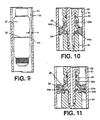
- FIGURE 9 The importance of centralizing the chemical cutter during the cutting operation can be illustrated by referring to FIGURE 9.
- Activated chemical is forced through the head section 27 and then through the ports 28, impinging on the internal surface 110 of the wellbore pipe 14, producing a tremendous exothermic reaction between halogen fluoride and the metal cutting surface.
- White hot temperatures in excess of 1,093 o C are generated immediately in the space between the cutting ports and the inside diameter of the pipe adjacent the head assembly 27.
- Copper is a relatively inexpensive metal that will conduct the heat away from the ports 28 fast enough to avoid vast damage to the tool.
- the value of the temperature from the area 111 of this chemical reaction varies approximately inversely the square of the distance from this reaction point.
- the head assembly 27 If the head assembly 27 is in a decentralized position against the pipe string 14 during the cutting operation the area closest to the pipe will be subjected to extreme temperatures causing non-repairable damage to the ports 28 by actually burning large holes in the head assembly 27, rendering the assembly unusable. From experience, it has been found that if the distance s is greater than about 0.32 cm , damage to the head assembly does not occur during the cutting cycle. Therefore, a tool that is improperly centralized can experience damage to the head assembly, by having large holes burned in the port area. The head assembly is an expensive component and is normally reusable from five to twenty times, if it is not damaged. Additionally, experience has shown that good centralization of the head assembly will nearly always make a complete cut.
- FIGURE 10 there is shown a cross-sectional view of slip array 80 in the deployed position.
- Slip array 80 is designed to anchor and centralize the chemical cutter in 7.30 cm outside diameter pipe.
- Slip array 80 is interchangeable with slip array 38 FIGURE 2 and is also installed in slip piston 36 employing slip shaft 32 and expansion mandrel 44. Downward movement of slip piston 36 will force slip array 80 against the tapered frusto conical surface 44b and in cooperation with ball bearings 44a serve to splay the slips segments 80 against the inside surface 81 of a wellbore pipe 82, anchoring and centralizing the chemical cutter during the cutting operation.
- slip array 80 is constructed with the same oblate torus configuration 38a and utilizes the same garter spring 40 as slip array 38 in FIGURE 2.
- FIGURE 11 is a cross-sectional view of a slip array 95 in the deployed position.
- the slip array 95 is designed to anchor and centralize the chemical cutter 18 (FIGURE 1) in 4 inch outside diameter pipe.
- Slip array 95 is interchangeable with slip array 38 and is also installed in slip piston 36 employing slip shaft 32 but employing a different slip expansion mandrel 94.
- Expansion mandrel 94 is constructed with two rows of concentric ball bearings 94a and 94b mounted in the tapered frusto conical surface 94c and in cooperation with ball bearings 94a and 94b serves to splay slip segments 95 against inside surface 91 of wellbore pipe 92 anchoring and centralizing the chemical cutter during the cutting operation.
- Ball bearings 94a and 94b are mounted on surface 94c to create a surface on which slip segments 95 ride. Ball bearings 94a and 94b eliminate the need to harden the upper surface of the expansion mandrel 94. As the slip segments 95 are forced against the expansion mandrel 94 the initial expansion of the slip segments 95 are accomplished by contacting first concentric row of ball bearing 94a and then the final expansion of slip segments 95 against inside surface 91 of wellbore pipe 92 is accomplished by the second concentric row of ball bearings 94b. It will be noted by viewing FIGURE 11 that slip array 95 is constructed with the same size oblate torus configuration 38a and utilizes the same garter spring 40 as slip array 38.
- each of the interchangeable slip arrays incorporate slip segments having serrated gripping teeth configured in relationships to accommodate different pipe sizes.
- the serrated gripping teeth are configured in a relationship in which the teeth simultaneously touches a locus defined by a diametrically specified cylindrical surface which is coaxial with the slip array.
- the locus is defined by a cylindrical surface having diameter of 6.35 cm
- the deployment angle for this slip array is about 20° as described previously.
- the locus of engagement of the serrated gripping teeth is a cylindrical surface having a diameter of about 8.89 cm.
- the deployment angle is about 46°, and as described above, the expansion mandrel will be exchanged with a larger expansion mandrel as described above.
- the locus of engagement by the serrated gripping teeth will be defined by a cylindrical surface coaxial with the slip shaft and having a diameter of 5.08 cm.
- the deployment angle usually is slightly less than that described above, i.e. about 18°, although the deployment angle can be substantially the same as the deployment angle used for the intermediate slip array.
- the smaller cylindrical locus is accommodated partially or entirely (for a deployment angle of 20°) by slightly smaller measurements corresponding to T g and T k disclosed in FIGURE 8a. In every case, the deployment angle is sufficiently great to provide a radially outward force component which is adequate to firmly anchor and center the cutting tool during the cutting operation.
Landscapes
- Engineering & Computer Science (AREA)
- Geology (AREA)
- Life Sciences & Earth Sciences (AREA)
- Mining & Mineral Resources (AREA)
- Environmental & Geological Engineering (AREA)
- Fluid Mechanics (AREA)
- Physics & Mathematics (AREA)
- General Life Sciences & Earth Sciences (AREA)
- Geochemistry & Mineralogy (AREA)
- Mechanical Engineering (AREA)
- Chemical & Material Sciences (AREA)
- Chemical Kinetics & Catalysis (AREA)
- General Chemical & Material Sciences (AREA)
- Excavating Of Shafts Or Tunnels (AREA)
- Earth Drilling (AREA)
Applications Claiming Priority (2)
| Application Number | Priority Date | Filing Date | Title |
|---|---|---|---|
| US07/275,265 US4971146A (en) | 1988-11-23 | 1988-11-23 | Downhole chemical cutting tool |
| US275265 | 1988-11-23 |
Publications (3)
| Publication Number | Publication Date |
|---|---|
| EP0370591A2 true EP0370591A2 (de) | 1990-05-30 |
| EP0370591A3 EP0370591A3 (de) | 1991-08-14 |
| EP0370591B1 EP0370591B1 (de) | 1995-08-09 |
Family
ID=23051539
Family Applications (1)
| Application Number | Title | Priority Date | Filing Date |
|---|---|---|---|
| EP89250092A Expired - Lifetime EP0370591B1 (de) | 1988-11-23 | 1989-11-20 | Chemisches Schneidwerkzeug für Bohrlöcher |
Country Status (4)
| Country | Link |
|---|---|
| US (1) | US4971146A (de) |
| EP (1) | EP0370591B1 (de) |
| CA (1) | CA2003434C (de) |
| DE (1) | DE68923764D1 (de) |
Cited By (8)
| Publication number | Priority date | Publication date | Assignee | Title |
|---|---|---|---|---|
| WO1992009785A1 (en) * | 1990-11-27 | 1992-06-11 | Pipe Recovery Consultants Limited | Device for a down-hole assembly |
| WO2003069115A3 (en) * | 2002-02-11 | 2004-02-12 | Baker Hughes Inc | Method of repair of collapsed or damaged tubulars downhole |
| GB2369639B (en) * | 1999-07-07 | 2004-02-18 | Schlumberger Technology Corp | Downhole anchoring tools conveyed by non-rigid carriers |
| EP1596120A1 (de) * | 2004-05-11 | 2005-11-16 | Gaz De France | In eine Leitung Einsetzbare Vorrichtung mit verbesserter Fixierung |
| US7128146B2 (en) | 2003-02-28 | 2006-10-31 | Baker Hughes Incorporated | Compliant swage |
| EA039477B1 (ru) * | 2018-01-19 | 2022-01-31 | Кобольд Корпорейшн | Толкатель для скважинного инструмента |
| EP4467765A1 (de) * | 2023-05-23 | 2024-11-27 | Welltec A/S | Bohrloch-radialkraftwerkzeuganordnung |
| WO2024240839A1 (en) * | 2023-05-23 | 2024-11-28 | Welltec A/S | Downhole radial force tool assembly |
Families Citing this family (58)
| Publication number | Priority date | Publication date | Assignee | Title |
|---|---|---|---|---|
| US5322118A (en) * | 1992-06-16 | 1994-06-21 | Terrell Jamie B | Downhole chemical cutter |
| US5320174A (en) * | 1992-06-16 | 1994-06-14 | Terrell Donna K | Downhole chemical cutting tool and process |
| US5287920A (en) * | 1992-06-16 | 1994-02-22 | Terrell Donna K | Large head downhole chemical cutting tool |
| US5626786A (en) * | 1995-04-17 | 1997-05-06 | Huntington; John H. | Labile bromine fire suppressants |
| US5575331A (en) * | 1995-06-07 | 1996-11-19 | Halliburton Company | Chemical cutter |
| US6536520B1 (en) | 2000-04-17 | 2003-03-25 | Weatherford/Lamb, Inc. | Top drive casing system |
| US6742596B2 (en) | 2001-05-17 | 2004-06-01 | Weatherford/Lamb, Inc. | Apparatus and methods for tubular makeup interlock |
| US7509722B2 (en) | 1997-09-02 | 2009-03-31 | Weatherford/Lamb, Inc. | Positioning and spinning device |
| CA2227354A1 (en) | 1998-01-16 | 1999-07-16 | Joe Hrupp | Perforating gun brake |
| GB9815809D0 (en) | 1998-07-22 | 1998-09-16 | Appleton Robert P | Casing running tool |
| GB2340859A (en) | 1998-08-24 | 2000-03-01 | Weatherford Lamb | Method and apparatus for facilitating the connection of tubulars using a top drive |
| GB2340857A (en) | 1998-08-24 | 2000-03-01 | Weatherford Lamb | An apparatus for facilitating the connection of tubulars and alignment with a top drive |
| GB2340858A (en) * | 1998-08-24 | 2000-03-01 | Weatherford Lamb | Methods and apparatus for facilitating the connection of tubulars using a top drive |
| GB2345074A (en) | 1998-12-24 | 2000-06-28 | Weatherford Lamb | Floating joint to facilitate the connection of tubulars using a top drive |
| US7325610B2 (en) | 2000-04-17 | 2008-02-05 | Weatherford/Lamb, Inc. | Methods and apparatus for handling and drilling with tubulars or casing |
| US6935423B2 (en) * | 2000-05-02 | 2005-08-30 | Halliburton Energy Services, Inc. | Borehole retention device |
| US7383876B2 (en) * | 2001-08-03 | 2008-06-10 | Weatherford/Lamb, Inc. | Cutting tool for use in a wellbore tubular |
| US6994176B2 (en) | 2002-07-29 | 2006-02-07 | Weatherford/Lamb, Inc. | Adjustable rotating guides for spider or elevator |
| US7503397B2 (en) | 2004-07-30 | 2009-03-17 | Weatherford/Lamb, Inc. | Apparatus and methods of setting and retrieving casing with drilling latch and bottom hole assembly |
| US7874352B2 (en) | 2003-03-05 | 2011-01-25 | Weatherford/Lamb, Inc. | Apparatus for gripping a tubular on a drilling rig |
| CA2517895C (en) | 2003-03-05 | 2009-12-01 | Weatherford/Lamb, Inc. | Casing running and drilling system |
| WO2004090279A1 (en) | 2003-04-04 | 2004-10-21 | Weatherford/Lamb, Inc. | Method and apparatus for handling wellbore tubulars |
| US6990879B2 (en) * | 2003-12-29 | 2006-01-31 | Rubino Daniel L | Drain line re-perforator device |
| US7284617B2 (en) | 2004-05-20 | 2007-10-23 | Weatherford/Lamb, Inc. | Casing running head |
| DE602005006198T2 (de) | 2004-07-20 | 2009-07-09 | Weatherford/Lamb, Inc., Houston | Oberantrieb zur Verbindung von Futterrohren |
| CA2591669C (en) * | 2005-01-12 | 2013-03-19 | Eclipse Aviation Corporation | Fire suppression systems |
| CA2532907C (en) | 2005-01-12 | 2008-08-12 | Weatherford/Lamb, Inc. | One-position fill-up and circulating tool |
| CA2533115C (en) | 2005-01-18 | 2010-06-08 | Weatherford/Lamb, Inc. | Top drive torque booster |
| AR054429A1 (es) * | 2006-03-06 | 2007-06-27 | Carro Gustavo Ignacio | Disposicion de anclaje para el entubamineto de pozos |
| US7445050B2 (en) * | 2006-04-25 | 2008-11-04 | Canrig Drilling Technology Ltd. | Tubular running tool |
| CA2586317C (en) | 2006-04-27 | 2012-04-03 | Weatherford/Lamb, Inc. | Torque sub for use with top drive |
| US7882902B2 (en) | 2006-11-17 | 2011-02-08 | Weatherford/Lamb, Inc. | Top drive interlock |
| US7552764B2 (en) * | 2007-01-04 | 2009-06-30 | Nabors Global Holdings, Ltd. | Tubular handling device |
| US8127560B2 (en) * | 2007-06-01 | 2012-03-06 | Carleton Life Support Systems, Inc. | Machined spring with integral retainer for closed cycle cryogenic coolers |
| US7886834B2 (en) | 2007-09-18 | 2011-02-15 | Schlumberger Technology Corporation | Anchoring system for use in a wellbore |
| US8286716B2 (en) * | 2007-09-19 | 2012-10-16 | Schlumberger Technology Corporation | Low stress traction system |
| US8720541B2 (en) * | 2008-06-26 | 2014-05-13 | Canrig Drilling Technology Ltd. | Tubular handling device and methods |
| US8074711B2 (en) | 2008-06-26 | 2011-12-13 | Canrig Drilling Technology Ltd. | Tubular handling device and methods |
| CA2771199C (en) * | 2009-08-24 | 2016-11-01 | Stream-Flo Industries Ltd. | Casing head connector |
| US9175520B2 (en) * | 2009-09-30 | 2015-11-03 | Baker Hughes Incorporated | Remotely controlled apparatus for downhole applications, components for such apparatus, remote status indication devices for such apparatus, and related methods |
| WO2011041562A2 (en) | 2009-09-30 | 2011-04-07 | Baker Hughes Incorporated | Remotely controlled apparatus for downhole applications and methods of operation |
| US8378218B2 (en) | 2009-11-13 | 2013-02-19 | Carleton Life Support Systems, Inc. | Spring with multiple conducting coils |
| US20110198099A1 (en) * | 2010-02-16 | 2011-08-18 | Zierolf Joseph A | Anchor apparatus and method |
| US8459358B2 (en) * | 2010-05-20 | 2013-06-11 | Baker Hughes Incorporated | Cutting dart and method of using the cutting dart |
| US8936088B2 (en) | 2010-05-20 | 2015-01-20 | Baker Hughes Incorporated | Cutting assembly and method of cutting coiled tubing |
| CN103132939B (zh) * | 2012-12-21 | 2017-02-22 | 贵州航天凯山石油仪器有限公司 | 一种智能投捞仪器的锚定方法及装置 |
| US10774602B2 (en) | 2013-12-20 | 2020-09-15 | Halliburton Energy Services, Inc. | High radial expansion anchoring tool |
| EP3055483A1 (de) * | 2013-12-27 | 2016-08-17 | Halliburton Energy Services, Inc. | Bremsen eines bohrlochwerkzeugstrangs |
| US9057230B1 (en) | 2014-03-19 | 2015-06-16 | Ronald C. Parsons | Expandable tubular with integral centralizers |
| CA2916422C (en) | 2014-12-29 | 2020-09-22 | Ncs Multistage Inc. | Tool for opening and closing sleeves within a wellbore |
| CA2965068C (en) | 2016-04-22 | 2023-11-14 | Ncs Multistage Inc. | Apparatus, systems and methods for controlling flow communication with a subterranean formation |
| US11248427B2 (en) | 2018-08-06 | 2022-02-15 | Schlumberger Technology Corporation | Systems and methods for manipulating wellbore completion products |
| CN109138856B (zh) * | 2018-11-22 | 2023-11-10 | 重庆科技学院 | 连续油管连接器 |
| US10968712B1 (en) * | 2019-10-25 | 2021-04-06 | Baker Hughes Oilfield Operations Llc | Adaptable anchor, system and method |
| CN115917115A (zh) * | 2020-05-02 | 2023-04-04 | 斯伦贝谢技术有限公司 | 用于定位移位轮廓几何的系统和方法 |
| WO2021226220A1 (en) * | 2020-05-07 | 2021-11-11 | Baker Hughes Oilfield Operations Llc | Chemical injection system for completed wellbores |
| CN115628027B (zh) * | 2022-12-19 | 2023-03-21 | 四川康克石油科技有限公司 | 一种用于油管的机械外切割工具 |
| US12392207B2 (en) * | 2023-11-14 | 2025-08-19 | Baker Hughes Oilfield Operations Llc | Anchor, method, and system |
Family Cites Families (10)
| Publication number | Priority date | Publication date | Assignee | Title |
|---|---|---|---|---|
| US2918125A (en) * | 1955-05-09 | 1959-12-22 | William G Sweetman | Chemical cutting method and apparatus |
| US2965031A (en) * | 1957-10-11 | 1960-12-20 | Seismograph Service Corp | Well bore detector and perforating apparatus |
| US3076507A (en) * | 1958-05-16 | 1963-02-05 | William G Sweetman | Chemical cutting method and apparatus for use in wells |
| DE1911900A1 (de) * | 1969-03-08 | 1970-09-24 | Longyear Diamond Core Drill Su | Seitenfeststeller fuer Bohrlochgeraete |
| GB1565004A (en) * | 1977-04-18 | 1980-04-16 | Weatherford Dmc | Chemical cutting appratus and method for use in wells |
| US4345646A (en) * | 1978-02-13 | 1982-08-24 | Gearhart Industries, Inc. | Apparatus for chemical cutting |
| US4415029A (en) * | 1981-07-23 | 1983-11-15 | Gearhart Industries, Inc. | Downhole well tool and anchoring assembly |
| US4619318A (en) * | 1984-09-27 | 1986-10-28 | Gearhart Industries, Inc. | Chemical cutting method and apparatus |
| US4620591A (en) * | 1985-04-12 | 1986-11-04 | Gearhart Industries, Inc. | Chemical cutting apparatus having selective pressure bleed-off |
| US4637471A (en) * | 1985-04-30 | 1987-01-20 | Soderberg Research & Development, Inc. | Tubing drain valve useful with heavy, sand-bearing oil |
-
1988
- 1988-11-23 US US07/275,265 patent/US4971146A/en not_active Expired - Lifetime
-
1989
- 1989-11-20 DE DE68923764T patent/DE68923764D1/de not_active Expired - Lifetime
- 1989-11-20 EP EP89250092A patent/EP0370591B1/de not_active Expired - Lifetime
- 1989-11-21 CA CA002003434A patent/CA2003434C/en not_active Expired - Fee Related
Cited By (19)
| Publication number | Priority date | Publication date | Assignee | Title |
|---|---|---|---|---|
| WO1992009785A1 (en) * | 1990-11-27 | 1992-06-11 | Pipe Recovery Consultants Limited | Device for a down-hole assembly |
| GB2261685A (en) * | 1990-11-27 | 1993-05-26 | Pipe Recovery Consultants Limi | Device for a down-hole assembly |
| GB2261685B (en) * | 1990-11-27 | 1994-12-07 | Pipe Recovery Consultants Limi | Device for a down-hole assembly |
| GB2369639B (en) * | 1999-07-07 | 2004-02-18 | Schlumberger Technology Corp | Downhole anchoring tools conveyed by non-rigid carriers |
| WO2003069115A3 (en) * | 2002-02-11 | 2004-02-12 | Baker Hughes Inc | Method of repair of collapsed or damaged tubulars downhole |
| GB2402415A (en) * | 2002-02-11 | 2004-12-08 | Baker Hughes Inc | Method of repair of collapsed or damaged tubulars downhole |
| GB2402415B (en) * | 2002-02-11 | 2005-10-12 | Baker Hughes Inc | Method of repair of collapsed or damaged tubulars downhole |
| GB2413818A (en) * | 2002-02-11 | 2005-11-09 | Baker Hughes Inc | Method of repair of collapsed or damaged tubulars downhole |
| AU2003210914B2 (en) * | 2002-02-11 | 2007-08-23 | Baker Hughes Incorporated | Repair of collapsed or damaged tubulars downhole |
| US7222669B2 (en) | 2002-02-11 | 2007-05-29 | Baker Hughes Incorporated | Method of repair of collapsed or damaged tubulars downhole |
| GB2413818B (en) * | 2002-02-11 | 2006-05-31 | Baker Hughes Inc | Method of repair of collapsed or damaged tubulars downhole |
| US7114559B2 (en) | 2002-02-11 | 2006-10-03 | Baker Hughes Incorporated | Method of repair of collapsed or damaged tubulars downhole |
| US7128146B2 (en) | 2003-02-28 | 2006-10-31 | Baker Hughes Incorporated | Compliant swage |
| FR2870316A1 (fr) * | 2004-05-11 | 2005-11-18 | Gaz De France | Dispositif inserable dans une canalisation, a capacite accrue de maintien en place |
| EP1596120A1 (de) * | 2004-05-11 | 2005-11-16 | Gaz De France | In eine Leitung Einsetzbare Vorrichtung mit verbesserter Fixierung |
| EA039477B1 (ru) * | 2018-01-19 | 2022-01-31 | Кобольд Корпорейшн | Толкатель для скважинного инструмента |
| EP4467765A1 (de) * | 2023-05-23 | 2024-11-27 | Welltec A/S | Bohrloch-radialkraftwerkzeuganordnung |
| WO2024240839A1 (en) * | 2023-05-23 | 2024-11-28 | Welltec A/S | Downhole radial force tool assembly |
| US12571273B2 (en) | 2023-05-23 | 2026-03-10 | Welltec A/S | Downhole radial force tool assembly |
Also Published As
| Publication number | Publication date |
|---|---|
| DE68923764D1 (de) | 1995-09-14 |
| EP0370591A3 (de) | 1991-08-14 |
| CA2003434C (en) | 1999-01-26 |
| US4971146A (en) | 1990-11-20 |
| CA2003434A1 (en) | 1990-05-23 |
| EP0370591B1 (de) | 1995-08-09 |
Similar Documents
| Publication | Publication Date | Title |
|---|---|---|
| US4971146A (en) | Downhole chemical cutting tool | |
| EP0575114B1 (de) | Chemisches Grosskopf-Schneidwerkzeug für Bohrlöcher | |
| US4345646A (en) | Apparatus for chemical cutting | |
| US7134504B2 (en) | Expandable packer with anchoring feature | |
| US7051805B2 (en) | Expandable packer with anchoring feature | |
| US4415029A (en) | Downhole well tool and anchoring assembly | |
| EP3592940B1 (de) | Bohrlochankermechanismus | |
| US7963341B2 (en) | Apparatus and methods of use for a whipstock anchor | |
| US4494601A (en) | Downhole chemical cutting tool | |
| US6929063B2 (en) | Cutting locator tool | |
| US12104446B2 (en) | System for dislodging and extracting tubing from a wellbore | |
| CA2119504A1 (en) | Apparatus for releasing perforating gun equipment from a well casing | |
| US20070187113A1 (en) | Method and apparatus for expanding tubulars in a wellbore | |
| US5054555A (en) | Tension-actuated mechanical detonating device useful for detonating downhole explosive | |
| US20240401426A1 (en) | System for dislodging and extracting tubing from a wellbore | |
| EP0699818B1 (de) | Werkzeugaufhänger im Bohrloch | |
| US6152233A (en) | Surge anchor assembly | |
| GB2124678A (en) | Apparatus for chemical cutting | |
| CA1184843A (en) | Apparatus for chemical cutting |
Legal Events
| Date | Code | Title | Description |
|---|---|---|---|
| PUAI | Public reference made under article 153(3) epc to a published international application that has entered the european phase |
Free format text: ORIGINAL CODE: 0009012 |
|
| AK | Designated contracting states |
Kind code of ref document: A2 Designated state(s): BE DE FR GB NL |
|
| PUAL | Search report despatched |
Free format text: ORIGINAL CODE: 0009013 |
|
| AK | Designated contracting states |
Kind code of ref document: A3 Designated state(s): BE DE FR GB NL |
|
| 17P | Request for examination filed |
Effective date: 19920205 |
|
| 17Q | First examination report despatched |
Effective date: 19930210 |
|
| GRAA | (expected) grant |
Free format text: ORIGINAL CODE: 0009210 |
|
| AK | Designated contracting states |
Kind code of ref document: B1 Designated state(s): BE DE FR GB NL |
|
| PG25 | Lapsed in a contracting state [announced via postgrant information from national office to epo] |
Ref country code: NL Free format text: LAPSE BECAUSE OF NON-PAYMENT OF DUE FEES Effective date: 19950809 |
|
| REF | Corresponds to: |
Ref document number: 68923764 Country of ref document: DE Date of ref document: 19950914 |
|
| ET | Fr: translation filed | ||
| PG25 | Lapsed in a contracting state [announced via postgrant information from national office to epo] |
Ref country code: DE Effective date: 19951110 |
|
| NLV1 | Nl: lapsed or annulled due to failure to fulfill the requirements of art. 29p and 29m of the patents act | ||
| PLBE | No opposition filed within time limit |
Free format text: ORIGINAL CODE: 0009261 |
|
| STAA | Information on the status of an ep patent application or granted ep patent |
Free format text: STATUS: NO OPPOSITION FILED WITHIN TIME LIMIT |
|
| 26N | No opposition filed | ||
| PGFP | Annual fee paid to national office [announced via postgrant information from national office to epo] |
Ref country code: BE Payment date: 19971212 Year of fee payment: 9 |
|
| PG25 | Lapsed in a contracting state [announced via postgrant information from national office to epo] |
Ref country code: BE Free format text: LAPSE BECAUSE OF NON-PAYMENT OF DUE FEES Effective date: 19981130 |
|
| BERE | Be: lapsed |
Owner name: TERRELL JAMIE B. Effective date: 19981130 |
|
| PGFP | Annual fee paid to national office [announced via postgrant information from national office to epo] |
Ref country code: GB Payment date: 19991117 Year of fee payment: 11 |
|
| PG25 | Lapsed in a contracting state [announced via postgrant information from national office to epo] |
Ref country code: GB Free format text: LAPSE BECAUSE OF NON-PAYMENT OF DUE FEES Effective date: 20001120 |
|
| GBPC | Gb: european patent ceased through non-payment of renewal fee |
Effective date: 20001120 |
|
| PGFP | Annual fee paid to national office [announced via postgrant information from national office to epo] |
Ref country code: FR Payment date: 20011113 Year of fee payment: 13 |
|
| PG25 | Lapsed in a contracting state [announced via postgrant information from national office to epo] |
Ref country code: FR Free format text: LAPSE BECAUSE OF NON-PAYMENT OF DUE FEES Effective date: 20030731 |
|
| REG | Reference to a national code |
Ref country code: FR Ref legal event code: ST |