EP4467724A1 - Front loader - Google Patents
Front loader Download PDFInfo
- Publication number
- EP4467724A1 EP4467724A1 EP22922042.1A EP22922042A EP4467724A1 EP 4467724 A1 EP4467724 A1 EP 4467724A1 EP 22922042 A EP22922042 A EP 22922042A EP 4467724 A1 EP4467724 A1 EP 4467724A1
- Authority
- EP
- European Patent Office
- Prior art keywords
- stand
- boom
- front loader
- lock plate
- link mechanism
- Prior art date
- Legal status (The legal status is an assumption and is not a legal conclusion. Google has not performed a legal analysis and makes no representation as to the accuracy of the status listed.)
- Pending
Links
Images






Classifications
-
- E—FIXED CONSTRUCTIONS
- E02—HYDRAULIC ENGINEERING; FOUNDATIONS; SOIL SHIFTING
- E02F—DREDGING; SOIL-SHIFTING
- E02F3/00—Dredgers; Soil-shifting machines
- E02F3/04—Dredgers; Soil-shifting machines mechanically-driven
- E02F3/627—Devices to connect beams or arms to tractors or similar self-propelled machines, e.g. drives therefor
- E02F3/6273—Devices to connect beams or arms to tractors or similar self-propelled machines, e.g. drives therefor using legs to support the beams or arms on the ground during the connecting process
-
- E—FIXED CONSTRUCTIONS
- E02—HYDRAULIC ENGINEERING; FOUNDATIONS; SOIL SHIFTING
- E02F—DREDGING; SOIL-SHIFTING
- E02F3/00—Dredgers; Soil-shifting machines
- E02F3/04—Dredgers; Soil-shifting machines mechanically-driven
- E02F3/28—Dredgers; Soil-shifting machines mechanically-driven with digging tools mounted on a dipper- or bucket-arm, i.e. there is either one arm or a pair of arms, e.g. dippers, buckets
- E02F3/34—Dredgers; Soil-shifting machines mechanically-driven with digging tools mounted on a dipper- or bucket-arm, i.e. there is either one arm or a pair of arms, e.g. dippers, buckets with bucket-arms, i.e. a pair of arms, e.g. manufacturing processes, form, geometry, material of bucket-arms directly pivoted on the frames of tractors or self-propelled machines
- E02F3/3405—Dredgers; Soil-shifting machines mechanically-driven with digging tools mounted on a dipper- or bucket-arm, i.e. there is either one arm or a pair of arms, e.g. dippers, buckets with bucket-arms, i.e. a pair of arms, e.g. manufacturing processes, form, geometry, material of bucket-arms directly pivoted on the frames of tractors or self-propelled machines and comprising an additional linkage mechanism
- E02F3/3411—Dredgers; Soil-shifting machines mechanically-driven with digging tools mounted on a dipper- or bucket-arm, i.e. there is either one arm or a pair of arms, e.g. dippers, buckets with bucket-arms, i.e. a pair of arms, e.g. manufacturing processes, form, geometry, material of bucket-arms directly pivoted on the frames of tractors or self-propelled machines and comprising an additional linkage mechanism of the Z-type
-
- E—FIXED CONSTRUCTIONS
- E02—HYDRAULIC ENGINEERING; FOUNDATIONS; SOIL SHIFTING
- E02F—DREDGING; SOIL-SHIFTING
- E02F9/00—Component parts of dredgers or soil-shifting machines, not restricted to one of the kinds covered by groups E02F3/00 - E02F7/00
- E02F9/006—Pivot joint assemblies
Definitions
- the present invention relates to a technique of a front loader mounted on a working vehicle such as a tractor.
- Patent Literature 1 discloses such a technique.
- Patent Literature 1 JP 2000-110190 A
- One aspect of the present disclosure has been made in view of the above circumstances, and an object of the present disclosure is to provide a front loader capable of easily holding a stand at a support position.
- the stand can be easily held at the support position by rocking the lock member.
- the link mechanism can be firmly locked by the lock member.
- space saving can be achieved by storing the link mechanism and the lock member in the stand and the boom.
- the lock member is formed in a shape capable of storing at least a part of the link mechanism in a state where the stand is rocked to the storage position.
- engagement and disengagement between the rocking shaft of the grounding part and the boom can be easily performed by moving the rocking shaft of the grounding part.
- the biasing part can hold the rocking shaft of the grounding part at the engagement position while holding the grounding part in a predetermined attitude.
- the machine body frame 2 is a frame-shaped member formed by appropriately combining a plurality of panel members.
- the machine body frame 2 is formed in a substantially rectangular shape in plan view.
- the machine body frame 2 is disposed with its longitudinal direction oriented in a front-rear direction.
- the engine 3 is fixed to a rear portion of the machine body frame 2.
- the transmission case 4 is fixed to a rear portion of the engine 3.
- a front portion of the machine body frame 2 is supported by the pair of left and right front wheels 5 through a front axle mechanism (not illustrated).
- a rear portion of the transmission case 4 is supported by the pair of left and right rear wheels 6 through a rear axle mechanism (not illustrated).
- the engine 3 is covered with the bonnet 7.
- the cabin 8 is provided behind the engine 3. Inside the cabin 8, a living space on which an operator boards is formed. In the living space, the steering wheel 9 for adjusting a turning angle of the front wheels 5, various operation tools, a seat on which the operator sits, and the like are disposed.
- the front loader 10 includes a side frame 20, a boom 30, a bucket 40, a stand 50, a link mechanism 60, and a lock plate 70.
- the booms 30 are rockably supported by the left and right side frames 20, respectively.
- the boom 30 is disposed so as to extend forward and downward from an upper portion of the side frame 20.
- the boom 30 is formed in a hollow shape having a bottom surface 30a, left and right side surfaces 30b, and an upper surface 30c.
- Lower end portions of the left and right side surfaces 30b are formed so as to protrude downward from the bottom surface 30a of the boom 30.
- a distance between the left and right side surfaces 30b (distance along the left-right direction) is formed to be longer than a left-right width of the stand 50 described later. In this way, the lower portion of the boom 30 is formed to be able to store the stand 50.
- a space below the boom 30 (a space surrounded by the bottom surface 30a and the left and right side surfaces 30b) is referred to as a "storage space S30".
- the boom 30 includes a cutout portion 30d and an engagement portion 30e.
- the cutout portion 30d is formed in a front-rear middle portion of the boom 30.
- the cutout portion 30d is formed in a shape in which the boom 30 is cut substantially upward.
- the engagement portion 30e is a portion to be engaged with the stand 50 described later.
- the engagement portion 30e is formed in a substantially inverted J shape in a side view.
- the engagement portion 30e is formed in front of the cutout portion 30d in a side view.
- the boom 30 configured as described above is provided with a lamp 31 and a boom cylinder 32.
- the lamp 31 is provided in the cutout portion 30d so as to be capable of irradiating the front lower side with light.
- the boom 30 can rock with respect to the side frame 20 by extension and contraction of the boom cylinder 32.
- the stand 50 allows the front loader 10 detached from the vehicle body of the tractor 1 to stand by itself.
- One stand 50 (a pair of right and left stands) is provided at each lower front portion of the right and left booms 30.
- the stand 50 can be switched between a storage position where the stand is stored in the boom 30 and a support position where the stand is grounded to support the weight of the front loader 10.
- One link mechanism 60 and one lock plate 70 are provided on each of the left and right stands 50.
- Figs. 2 to 8 illustrate the stand 50, the link mechanism 60, and the like switched to the support position.
- Figs. 9 to 12 illustrate the stand 50, the link mechanism 60, and the like switched to the storage position.
- the bottom surface portion 51a is a portion forming a bottom surface of the main body 51.
- the bottom surface portion 51a is formed in a plate shape with a plate surface oriented in the substantially vertical direction.
- the bottom surface portion 51a is formed to extend long in the longitudinal direction of the main body 51.
- the sliding portion 51d illustrated in Fig. 6 is a portion that guides the grounding part rocking shaft 53 described later so as to be slidable.
- the sliding portion 51d is formed by a pair of holes penetrating the main body 51 in the left-right direction.
- the sliding portion 51d is formed at a rear end portion of the left and right side surface portions 51b.
- the sliding portion 51d is formed in a long hole shape. A length of the sliding portion 51d is appropriately determined to such a length that the grounding part rocking shaft 53 and the engagement portion 30e (see Fig. 2 ) can be engaged or disengaged.
- the bracket 52a is for attaching the biasing part 54.
- the bracket 52a is formed in a substantially plate shape.
- a rear portion of the bracket 52a is fixed to a bottom surface of the grounding part 52.
- a front portion of the bracket 52a is formed so as to be inclined forward and upward with respect to the bottom surface of the grounding part 52.
- the grounding part rocking shaft 53 rockably couples the grounding part 52 to the main body 51.
- the grounding part rocking shaft 53 is formed in a substantially cylindrical shape with its axis oriented to the left and right.
- the grounding part rocking shaft 53 is formed so as to be engageable with the engagement portion 30e (see Fig. 2 ) of the boom 30.
- the grounding part rocking shaft 53 is inserted through the left and right side surfaces of the grounding part 52 and the sliding portion 51d of the main body 51.
- the grounding part rocking shaft 53 rockably couples the grounding part 52 to the main body 51.
- the grounding part rocking shaft 53 can slide in the sliding portion 51d along the longitudinal direction of the sliding portion 51d.
- the grounding part rocking shaft 53 can move to an engagement position and a release position by sliding in the sliding portion 51d.
- the engagement position is a position where the stand 50 can be engaged with the engagement portion 30e of the boom 30 to be described later in a case where the stand is at the storage position (see the grounding part rocking shaft 53 indicated by a solid line in Fig. 10 ).
- the release position is a position where the engagement with the engagement portion 30e can be released in a case where the stand 50 is at the storage position (see the grounding part rocking shaft 53 indicated by a two-dot chain line in Fig. 10 ).
- the biasing part 54 biases the grounding part 52.
- the biasing part 54 of the present embodiment is formed of a tension coil spring. One end of the biasing part 54 is attached to the bracket 51e of the main body 51. The other end of the biasing part 54 is attached to the bracket 52a of the grounding part 52.
- the biasing part 54 biases the grounding part 52. More specifically, the biasing part 54 biases the grounding part 52 such that the grounding part 52 rocks in one direction (clockwise direction in Fig. 6 in the present embodiment) in a rocking direction. Furthermore, the biasing part 54 biases the grounding part 52 such that the grounding part rocking shaft 53 is directed to one side (the front upper side in Fig. 6 in the present embodiment) of the sliding portion 51d.
- the link mechanism 60 illustrated in Figs. 3 , 4 , and 7 moves in conjunction with the rocking of the stand 50.
- the link mechanism 60 is configured to couple the boom 30 and the stand 50.
- the link mechanism 60 includes a first link member 61, a second link member 62, a coupling member 63, and a stopper 64.
- the second link member 62 is a substantially plate-like member coupled to the stand 50. As illustrated in Figs. 3 , 4 , and 7 , the second link member 62 is disposed with a plate surface oriented in the substantially left-right direction. The second link member 62 is formed in a linear shape extending long in one direction. A pair of the left and right second link members 62 is provided. The left and right second link members 62 are disposed on the left and right of the first link member. Lower end portions of the left and right second link members 62 are disposed inside the main body 51. The lower end portions of the second link members 62 are rockably supported by the main body 51 of the stand 50 through a coupling pin 62a whose axis is directed to the left and right.
- the coupling member 63 is a member that couples the first link member 61 and the second link members 62.
- the coupling member 63 is formed in a substantially cylindrical shape with its axis oriented to the left and right.
- the coupling member 63 is provided so as to laterally penetrate the first link member 61 and the second link members 62. In this way, the coupling member 63 rockably couples the first link member 61 and the second link members 62.
- the stopper 64 illustrated in Fig. 7 is for restricting rocking of the first link member 61 and the second link members 62.
- the stopper 64 is provided across the left and right second link members 62.
- the stopper 64 is disposed in front of the coupling member 63. In the state illustrated in Fig. 7 , the stopper 64 abuts on the first link member 61. Accordingly, the stopper 64 restricts rocking of the first link member 61 and the like. More specifically, the stopper 64 restricts rocking of the first link member 61 and the second link members 62 such that the lower end portion of the first link member 61 and the upper end portions of the second link members 62 move rearward from the state illustrated in Fig. 7 .
- the lock plate 70 illustrated in Figs. 7 and 8 is for holding the stand 50 at the support position.
- the lock plate 70 is formed in a linear shape extending long in one direction.
- the lock plate 70 is formed in a substantially U shape with an opening facing downward in a longitudinal direction cross-sectional view (see Fig. 12 ).
- the lock plate 70 includes a top plate portion 71 and a side surface portion 72.
- the top plate portion 71 is a portion forming an upper surface of the lock plate 70.
- the top plate portion 71 is formed in a plate shape with a plate surface facing substantially the vertical direction.
- the top plate portion 71 is formed to extend substantially in the front-rear direction (the longitudinal direction of the lock plate 70).
- the top plate portion 71 includes a cutout portion 71a.
- the cutout portion 71a is formed at a rear end portion of the top plate portion 71.
- the cutout portion 71a is formed in a recessed shape in which the top plate portion 71 is cut out substantially forward.
- a left-right width of the cutout portion 71a is formed to be substantially equal to a left-right width of the first link member 61.
- the side surface portion 72 is a portion forming a side surface of the lock plate 70.
- the side surface portion 72 is formed in a plate shape with a plate surface facing the left-right direction.
- a pair of the left and right side surface portions 72 is formed.
- the left side surface portion 72 is formed to extend substantially rearward more than the right side surface portion 72.
- a distance between the left and right side surface portions 72 (distance along the left-right direction) is formed to be longer than a left-right width of the link mechanism 60.
- the lock plate 70 of the present embodiment is formed in a shape capable of storing the link mechanism 60.
- the lock plate 70 configured as described above can be switched between a locked position and an unlocked position by rocking with respect to the boom 30.
- the locked position illustrated in Fig. 7 is a position at which the link mechanism 60 is locked at a predetermined position. More specifically, the locked position is a position where the lock plate 70 and the cutout portion 61b of the first link member 61 are engaged with each other.
- the top plate portion 71 (cutout portion 71a) is fitted in the cutout portion 61b of the first link member 61.
- the left side surface portion 72 is disposed so as to straddle the link mechanism 60 in the front-rear direction in side view.
- the unlocked position is a position where the link mechanism 60 is not locked.
- the unlocked position is a position where the engagement between the lock plate 70 and the cutout portion 61b of the first link member 61 is released.
- the top plate portion 71 cutout portion 71a
- the top plate portion 71 is located above the cutout portion 61b of the first link member 61 (see Fig. 13(a) ).
- the stand 50 is held by the boom 30 at the storage position by the grounding part rocking shaft 53 being engaged with the engagement portion 30e.
- the grounding part rocking shaft 53 is biased frontward and downward (in a direction to be engaged with the engagement portion 30e) by the biasing part 54.
- the engagement of the grounding part rocking shaft 53 is not released.
- vibration of the grounding part rocking shaft 53 can be suppressed, and generation of a collision sound between the grounding part rocking shaft 53 and the engagement portion 30e can be prevented.
- the boom 30 and the stand 50 are disposed such that the outer edge portions are continuous in a straight line in a side view. More specifically, the lower end portion of the boom 30, the bottom surface portion 51a of the main body 51, and the bottom surface of the grounding part 52 are located on a straight line L1 along the longitudinal direction of the stand 50 in a side view, and the lower end portions and the like of the boom 30 and the like are provided so as to be adjacent to each other in the longitudinal direction.
- the stand 50 can be assimilated with the boom 30 to give a sense of unity to the boom 30 and the stand 50, and the aesthetic appearance can be improved.
- the stand 50 is disposed so as not to generate a gap with respect to the boom 30 in a side view when being at the storage position. More specifically, the stand 50 is disposed along the lower end of the boom 30 without a gap with respect to the boom 30 in a side view. As a result, it is possible to prevent the appearance of the stand 50 from deteriorating and to improve the aesthetic appearance.
- the cutout portion 30d of the boom 30 of the present embodiment is continuous with the bottom surface of the grounding part 52 of the stand 50 in a side view in a case where the stand 50 is at the storage position.
- the lamp 31 of the front loader 10 is provided in the cutout portion 30d, and is disposed in an attitude capable of emitting light in the longitudinal direction of the stand 50 at the storage position. With such a configuration, it is possible to provide a sense of unity to the stand 50 and the lamp 31, and to improve the aesthetic appearance.
- the link mechanism 60 is disposed inside a space surrounded by the boom 30 and the stand 50 in a state where the first link member 61 and the second link members 62 are folded. In this way, the entire link mechanism 60 is stored in the boom 30 and the stand 50 in an invisible manner from the outside in a case where the stand 50 is at the storage position (see Fig. 9 ). Furthermore, similarly to the link mechanism 60, the entire lock plate 70 is stored in the boom 30 and the stand 50 so as to be invisible from the outside.
- first link member 61 and the second link members 62 of the link mechanism 60 are bent toward the lock plate 70 and are stored between the left and right side surface portions 72 of the lock plate 70 in a case where the stand 50 is at the storage position.
- a part of the link mechanism 60 (first link member 61) is stored in the lock plate 70.
- the link mechanism 60 and the lock plate 70 are appropriately stored in the boom 30 or the like, so that the link mechanism 60 and the lock plate 70 can be compactly put together to achieve space saving.
- the operator rocks the main body 51 downward.
- the first link member 61 and the second link members 62 illustrated in Fig. 11 are rocked with the rocking of the main body 51.
- the lock plate 70 is rocked downward by its own weight as the first link member 61 and the second link members 62 rock.
- the main body 51 is rocked by its own weight until the first link member 61 and the second link members 62 are arranged in a substantially straight line. More specifically, the main body 51 is rocked to a position where the coupling pins 61a and 62a and the coupling member 63 are aligned in a straight line in a side view. At this time, the lock plate 70 (the cutout portion 71a in Fig. 8 ) abuts on an upper side of the cutout portion 61b in the first link member 61. As described above, the lock plate 70 of the present embodiment does not move to the locked position even when the operator rocks the main body 51.
- the overcentered state refers to a state in which the coupling member 63 is located behind a straight line L2 connecting the coupling pins 61a and 62a (on the side farther from the rocking shaft 51c of the lock plate 70).
- the stopper 64 is brought into contact with the first link member 61 in a state where the first link member 61 and the second link members 62 are overcentered.
- the lock plate 70 is rocked downward from the state illustrated in Fig. 13(a) by the rocking of the first link member 61 and the like accompanying the pressing by the operator. As illustrated in Fig. 13(b) , the top plate portion 71 of the lock plate 70 is fitted in the cutout portion 61b of the first link member 61. Thus, the lock plate 70 is moved to the locked position. This completes switching of the stand 50 to the support position. Thus, the operator can easily lock the link mechanism 60 only by pressing the lock plate 70 downward.
- the grounding part 52 comes into contact with a ground contact surface (ground) and rocks with respect to the main body 51.
- the grounding part 52 is brought into surface contact with the ground contact surface, and the front loader 10 can be supported by the stand 50 in a stable state. Furthermore, it is possible to prevent the ground contact surface from being scratched.
- the operator can switch the stand 50 from the support position to the storage position by a procedure substantially reverse to the above procedure (procedure for switching the stand 50 from the storage position to the support position).
- the operator moves the lock plate 70 to the unlocked position by supporting the stand 50 and rocking the lock plate 70 upward (see Fig. 13(a) ). Furthermore, the operator releases the state in which the first link member 61 and the second link members 62 are overcentered. In this state, the operator rocks the stand 50 upward. The first link member 61, the second link members 62, and the lock plate 70 are rocked as the stand 50 rocks upward.
- the grounding part rocking shaft 53 is engaged with the engagement portion 30e of the boom 30.
- the front loader 10 includes the stand 50 that is provided in the boom 30 and is rockable to the support position where the front loader 10 can be supported and the storage position where the front loader is stored, the link mechanism 60 that couples the boom 30 and the stand 50 and is movable in conjunction with rocking of the stand 50, and the lock plate 70 (lock member) that is rockably provided in the boom 30 and holds the stand 50 at the support position by locking the link mechanism 60 at a predetermined position.
- the stand 50 can be easily held at the support position by rocking the lock plate 70.
- the link mechanism 60 includes a first link member 61 coupled to the boom 30 and a second link member 62 coupled to the stand 50, and the lock plate 70 locks the link mechanism 60 in a state where the first link member 61 and the second link members 62 are overcentered (see Fig. 13(b) ).
- the link mechanism 60 can be firmly locked by the lock plate 70.
- rocking shaft (rocking shaft 51c) of the lock plate 70 is disposed on the same axis as the rocking shaft (rocking shaft 51c) of the stand 50.
- the rocking shafts of the lock plate 70 and the stand 50 can be arranged on the same axis, and space saving can be achieved.
- the lock plate 70 is formed in a shape capable of storing at least a part of the link mechanism 60 in a state where the stand 50 is rocked to the storage position.
- the stand 50 includes the main body 51 rockably supported by the boom 30, and the grounding part 52 rockable with respect to the main body 51 and in contact with the ground when supporting the front loader 10, and a rocking shaft (grounding part rocking shaft 53) of the grounding part 52 is movable to an engagement position capable of engaging with the boom 30 and a release position capable of releasing the engagement with the boom 30 by moving with respect to the main body 51 (see Fig. 10 ).
- the stand 50 further includes the biasing part 54 that biases the grounding part 52 such that the grounding part 52 rocks in one direction in the rocking direction and the rocking shaft (grounding part rocking shaft 53) of the grounding part 52 moves toward the engagement position.
- the biasing part 54 can hold the rocking shaft of the grounding part 52 at the engagement position while holding the grounding part 52 in a predetermined attitude.
- the boom 30 and the stand 50 are disposed such that outer edge portions of the boom 30 and the stand 50 are continuous in a straight line in a side view in a state where the stand 50 is rocked to the storage position (see Fig. 9 ).
- lock plate 70 according to the present embodiment is an embodiment of the lock member according to the present invention.
- the working tool coupled to the boom 30 is not limited to the bucket 40 and can be arbitrarily changed.
- a snow blower, a snow blade, a sweeper, and the like may be coupled to the boom 30.
- two stands 50 (a pair of right and left stands) are provided, but the number of the stands 50 is not limited.
- the lock plate 70 locks the link mechanism 60 in a state where the first link member 61 and the second link members 62 are overcentered
- the state of the first link member 61 and the like at the time of locking is not particularly limited.
- the lock plate 70 may lock the link mechanism 60 in a state where the first link member 61 and the like are not overcentered.
- lock plate 70 is rocked to the locked position by the pressing of the operator, this is an example, and for example, the lock plate 70 may be automatically rocked to the locked position without being pressed by the operator.
- the link mechanism 60 and the lock plate 70 are entirely stored in the boom 30 and the stand 50 in a case where the stand 50 is at the storage position, but this is an example, and the link mechanism 60 and the lock plate 70 may be stored in the boom 30 or the like in any manner.
- the link mechanism 60 and the lock plate 70 may be stored in the boom 30 or the like, or a part of the link mechanism 60 and a part of the lock plate 70 may be stored in the boom 30 or the like.
- the boom 30 does not need to store each of the link mechanism 60 and the lock plate 70, and may store only the link mechanism 60, for example.
- the stand 50 does not need to store each of the link mechanism 60 and the lock plate 70, and may store only the lock plate 70, for example.
- link mechanism 60 is partially stored in the lock plate 70 in a case where the stand 50 is at the storage position, this is an example, and for example, the entire link mechanism 60 may be stored in the lock plate 70.
- biasing part 54 is formed of a tension coil spring, this is an example, and the biasing part 54 may be formed of a member other than the tension coil spring.
- the present invention can be used for a technique of a front loader mounted on a working vehicle such as a tractor.
Landscapes
- Engineering & Computer Science (AREA)
- Mining & Mineral Resources (AREA)
- Civil Engineering (AREA)
- General Engineering & Computer Science (AREA)
- Structural Engineering (AREA)
- Mechanical Engineering (AREA)
- Shovels (AREA)
Abstract
Description
- The present invention relates to a technique of a front loader mounted on a working vehicle such as a tractor.
- Conventionally, a technique related to a front loader mounted on a working vehicle such as a tractor has been known. For example, Patent Literature 1 discloses such a technique.
- Patent Literature 1 describes a stand for making a front loader stand by itself when the front loader is detached from a working vehicle. The stand is rockably coupled to a boom, and can be switched between a support attitude capable of supporting the boom and a storage attitude stored in the boom.
- However, in order to hold the stand described in Patent Literature 1 in a support attitude, it is necessary to fix the stand using a fixing pin, which is troublesome.
- Patent Literature 1:
JP 2000-110190 A - One aspect of the present disclosure has been made in view of the above circumstances, and an object of the present disclosure is to provide a front loader capable of easily holding a stand at a support position.
- The problem to be solved by one aspect of the present disclosure is as described above, and means for solving the problem will be described below.
- That is, one aspect of the present disclosure includes: a stand provided on a boom and rockable to a support position where the front loader can be supported and a storage position where the front loader is stored; a link mechanism that couples the boom and the stand and is movable in conjunction with rocking of the stand; and a lock member that is rockably provided on the boom and holds the stand at the support position by locking the link mechanism at a predetermined position.
- According to one aspect of the present disclosure, the stand can be easily held at the support position by rocking the lock member.
- In one aspect of the present disclosure, the link mechanism includes: a first link member coupled to the boom; and a second link member coupled to the stand, and the lock member locks the link mechanism in a state where the first link member and the second link member are overcentered.
- According to one aspect of the present disclosure, the link mechanism can be firmly locked by the lock member.
- In one aspect of the present disclosure, a rocking shaft of the lock member is disposed on the same axis as a rocking shaft of the stand.
- According to one aspect of the present disclosure, the rocking shafts of the lock member and the stand can be arranged on the same axis, and space saving can be achieved.
- In one aspect of the present disclosure, at least a part of the link mechanism and the lock member is stored in the stand and the boom in a state where the stand is rocked to the storage position.
- According to one aspect of the present disclosure, space saving can be achieved by storing the link mechanism and the lock member in the stand and the boom.
- In one aspect of the present disclosure, the lock member is formed in a shape capable of storing at least a part of the link mechanism in a state where the stand is rocked to the storage position.
- According to one aspect of the present disclosure, space saving can be achieved by storing the link mechanism in the lock member.
- According to an aspect of the present disclosure, the stand includes: a main body rockably supported by the boom; and a grounding part that is rockable with respect to the main body and is in contact with a ground when supporting the front loader, and a rocking shaft of the grounding part is movable to an engagement position capable of engaging with the boom and a release position capable of releasing the engagement with the boom by moving with respect to the main body.
- According to one aspect of the present disclosure, engagement and disengagement between the rocking shaft of the grounding part and the boom can be easily performed by moving the rocking shaft of the grounding part.
- In one aspect of the present disclosure, the stand further includes a biasing part that biases the grounding part such that the grounding part rocks in one direction in a rocking direction and the rocking shaft of the grounding part moves toward the engagement position.
- According to one aspect of the present disclosure, the biasing part can hold the rocking shaft of the grounding part at the engagement position while holding the grounding part in a predetermined attitude.
- In one aspect of the present disclosure, the boom and the stand are disposed such that outer edge portions of the boom and the stand are continuous in a straight line in a side view in a state where the stand is rocked to the storage position.
- According to one aspect of the present disclosure, the sense of unity between the boom and the stand can be provided, and the aesthetic appearance can be improved.
- According to one aspect of the present disclosure, the stand can be easily held in the support position.
-
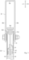
- FIG. 1
- is a side view illustrating an overall configuration of a tractor including a front loader according to an embodiment of the present invention.
- FIG. 2
- is a side view illustrating the front loader.
- FIG. 3
- is a cross-sectional view taken along line A1-A1.
- FIG. 4
- is a perspective view illustrating a stand.
- FIG. 5
- is a side view of the same.
- FIG. 6
- is a side sectional view illustrating a grounding part.
- FIG. 7
- is a side sectional view illustrating a link mechanism.
- FIG. 8
- is an enlarged perspective view illustrating a lock plate.
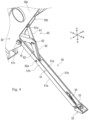
- FIG. 9
- is a side view illustrating the front loader in a case where the stand is at a storage position.
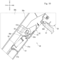
- FIG. 10
- is a side cross-sectional view illustrating the grounding part in a case where the stand is at the storage position.
- FIG. 11
- is a side sectional view illustrating the link mechanism in a case where the stand is at the storage position.
- FIG. 12
- is a cross-sectional view taken along line A2-A2.
- FIG. 13(a)
- is a schematic view illustrating a state before the lock plate is pushed downward.
- FIG. 13(b)
- is a schematic view illustrating a state after the lock plate is pushed downward.
- In the following description, directions indicated by arrows U, D, F, B, L, and R in the drawings are defined as an upward direction, a downward direction, a forward direction, a backward direction, a left direction, and a right direction, respectively.
- Hereinafter, the entire configuration of a tractor 1 including a
front loader 10 according to one embodiment of the present invention will be described. - As illustrated in
Fig. 1 , the tractor 1 mainly includes amachine body frame 2, anengine 3, a transmission case 4,front wheels 5,rear wheels 6, abonnet 7, acabin 8, asteering wheel 9, and afront loader 10. - The
machine body frame 2 is a frame-shaped member formed by appropriately combining a plurality of panel members. Themachine body frame 2 is formed in a substantially rectangular shape in plan view. Themachine body frame 2 is disposed with its longitudinal direction oriented in a front-rear direction. Theengine 3 is fixed to a rear portion of themachine body frame 2. The transmission case 4 is fixed to a rear portion of theengine 3. A front portion of themachine body frame 2 is supported by the pair of left and rightfront wheels 5 through a front axle mechanism (not illustrated). A rear portion of the transmission case 4 is supported by the pair of left and rightrear wheels 6 through a rear axle mechanism (not illustrated). Theengine 3 is covered with thebonnet 7. - Power of the
engine 3 can be transmitted to thefront wheels 5 through the front axle mechanism and can be transmitted to therear wheels 6 through the rear axle mechanism after being shifted by a transmission device (not illustrated) stored in the transmission case 4. Thefront wheels 5 and therear wheels 6 are rotationally driven by the power of theengine 3, and the tractor 1 can travel. - The
cabin 8 is provided behind theengine 3. Inside thecabin 8, a living space on which an operator boards is formed. In the living space, thesteering wheel 9 for adjusting a turning angle of thefront wheels 5, various operation tools, a seat on which the operator sits, and the like are disposed. - The
front loader 10 is mounted to a front portion of the tractor 1. Hereinafter, a detailed configuration of thefront loader 10 will be described with reference toFigs. 2 to 8 . - As illustrated in
Fig. 2 , thefront loader 10 includes aside frame 20, aboom 30, abucket 40, astand 50, alink mechanism 60, and alock plate 70. - The
side frame 20 is detachably attached to a vehicle body (themachine body frame 2 and the transmission case 4) of the tractor 1. The side frames 20 are provided on the left and right of the vehicle body. - The
booms 30 are rockably supported by the left and right side frames 20, respectively. Theboom 30 is disposed so as to extend forward and downward from an upper portion of theside frame 20. As illustrated inFig. 3 , theboom 30 is formed in a hollow shape having abottom surface 30a, left and right side surfaces 30b, and anupper surface 30c. Lower end portions of the left and right side surfaces 30b are formed so as to protrude downward from thebottom surface 30a of theboom 30. Furthermore, a distance between the left and right side surfaces 30b (distance along the left-right direction) is formed to be longer than a left-right width of thestand 50 described later. In this way, the lower portion of theboom 30 is formed to be able to store thestand 50. Hereinafter, a space below the boom 30 (a space surrounded by thebottom surface 30a and the left and right side surfaces 30b) is referred to as a "storage space S30". As illustrated inFig. 2 , theboom 30 includes acutout portion 30d and anengagement portion 30e. - The
cutout portion 30d is formed in a front-rear middle portion of theboom 30. Thecutout portion 30d is formed in a shape in which theboom 30 is cut substantially upward. - The
engagement portion 30e is a portion to be engaged with thestand 50 described later. Theengagement portion 30e is formed in a substantially inverted J shape in a side view. Theengagement portion 30e is formed in front of thecutout portion 30d in a side view. - The
boom 30 configured as described above is provided with alamp 31 and aboom cylinder 32. Thelamp 31 is provided in thecutout portion 30d so as to be capable of irradiating the front lower side with light. Theboom 30 can rock with respect to theside frame 20 by extension and contraction of theboom cylinder 32. - The
bucket 40 is formed to open forward. Thebucket 40 is rockably coupled to a front end portion of theboom 30. Thebucket 40 is provided with abucket cylinder 41. Thebucket 40 can rock with respect to theboom 30 by extension and contraction of thebucket cylinder 41. - The
stand 50 allows thefront loader 10 detached from the vehicle body of the tractor 1 to stand by itself. One stand 50 (a pair of right and left stands) is provided at each lower front portion of the right and leftbooms 30. Thestand 50 can be switched between a storage position where the stand is stored in theboom 30 and a support position where the stand is grounded to support the weight of thefront loader 10. Onelink mechanism 60 and onelock plate 70 are provided on each of the left and right stands 50.Figs. 2 to 8 illustrate thestand 50, thelink mechanism 60, and the like switched to the support position. Furthermore,Figs. 9 to 12 illustrate thestand 50, thelink mechanism 60, and the like switched to the storage position. - Hereinafter, the configurations of the
stand 50, thelink mechanism 60, and thelock plate 70 will be described with reference to a state where thestand 50 is at the support position. Since thestand 50, thelink mechanism 60, and thelock plate 70 have the same configuration on the right and left, the configuration of thestand 50 and the like will be described below, taking thestand 50 and the like on the left side as an example. As illustrated inFigs. 4 and5 , thestand 50 includes amain body 51, a groundingpart 52, a groundingpart rocking shaft 53, and a biasingpart 54. - The
main body 51 is provided to be rockable with respect to theboom 30. Themain body 51 is formed in a longitudinal shape extending long in one direction. Themain body 51 is formed in a substantially U shape with an opening portion facing upward in a longitudinal direction cross-sectional view (seeFig. 12 ). A front end portion of themain body 51 is disposed in the storage space S30. Themain body 51 includes abottom surface portion 51a, aside surface portion 51b, a rockingshaft 51c, a slidingportion 51d (seeFig. 6 ), and abracket 51e. - The
bottom surface portion 51a is a portion forming a bottom surface of themain body 51. Thebottom surface portion 51a is formed in a plate shape with a plate surface oriented in the substantially vertical direction. Thebottom surface portion 51a is formed to extend long in the longitudinal direction of themain body 51. - The
side surface portion 51b is a portion forming a side surface of themain body 51. Theside surface portion 51b is formed in a plate shape with a plate surface facing the left-right direction. Theside surface portion 51b is formed over the entire region in the longitudinal direction of thebottom surface portion 51a. A distance between the left and rightside surface portions 51b (distance along the left-right direction) is formed to be longer than a left-right width of thelink mechanism 60 and thelock plate 70. In this way, thestand 50 of the present embodiment is formed in a shape capable of storing thelink mechanism 60 and thelock plate 70. - The rocking
shaft 51c rockably couples themain body 51 to theboom 30. The rockingshaft 51c is formed in a substantially cylindrical shape with its axis oriented to the left and right. In the present embodiment, a bolt longer than a left-right width of theboom 30 is used as the rockingshaft 51c. The rockingshaft 51c is inserted through a front lower portion of the boom 30 (side surface 30b) and a front end portion of theside surface portion 51b. As a result, themain body 51 is supported by theboom 30 so as to be rockable up and down. - The sliding
portion 51d illustrated inFig. 6 is a portion that guides the groundingpart rocking shaft 53 described later so as to be slidable. The slidingportion 51d is formed by a pair of holes penetrating themain body 51 in the left-right direction. The slidingportion 51d is formed at a rear end portion of the left and rightside surface portions 51b. The slidingportion 51d is formed in a long hole shape. A length of the slidingportion 51d is appropriately determined to such a length that the groundingpart rocking shaft 53 and theengagement portion 30e (seeFig. 2 ) can be engaged or disengaged. - The
bracket 51e illustrated inFigs. 4 and6 is for attaching the biasingpart 54 to be described later. Thebracket 51e is formed in a substantially plate shape. Thebracket 51e is formed in a longitudinal shape extending in substantially the same direction as the longitudinal direction of themain body 51. Both end portions of thebracket 51e in the longitudinal direction extend so as to be orthogonal to the longitudinal direction of themain body 51, and are fixed to thebottom surface portion 51a. - The grounding
part 52 is a portion that comes into contact with the ground when thefront loader 10 is supported by thestand 50. The groundingpart 52 is formed in a groove steel shape opened upward by bending both left and right end portions of a steel plate upward. The groundingpart 52 is disposed so as to overlap the rear end portion of themain body 51 in a side view. As illustrated inFig. 6 , the groundingpart 52 includes abracket 52a. - The
bracket 52a is for attaching the biasingpart 54. Thebracket 52a is formed in a substantially plate shape. A rear portion of thebracket 52a is fixed to a bottom surface of the groundingpart 52. A front portion of thebracket 52a is formed so as to be inclined forward and upward with respect to the bottom surface of the groundingpart 52. - The grounding
part rocking shaft 53 rockably couples the groundingpart 52 to themain body 51. The groundingpart rocking shaft 53 is formed in a substantially cylindrical shape with its axis oriented to the left and right. The groundingpart rocking shaft 53 is formed so as to be engageable with theengagement portion 30e (seeFig. 2 ) of theboom 30. The groundingpart rocking shaft 53 is inserted through the left and right side surfaces of the groundingpart 52 and the slidingportion 51d of themain body 51. As a result, the groundingpart rocking shaft 53 rockably couples the groundingpart 52 to themain body 51. Furthermore, the groundingpart rocking shaft 53 can slide in the slidingportion 51d along the longitudinal direction of the slidingportion 51d. - The grounding
part rocking shaft 53 can move to an engagement position and a release position by sliding in the slidingportion 51d. The engagement position is a position where thestand 50 can be engaged with theengagement portion 30e of theboom 30 to be described later in a case where the stand is at the storage position (see the groundingpart rocking shaft 53 indicated by a solid line inFig. 10 ). The release position is a position where the engagement with theengagement portion 30e can be released in a case where thestand 50 is at the storage position (see the groundingpart rocking shaft 53 indicated by a two-dot chain line inFig. 10 ). - The biasing
part 54 biases thegrounding part 52. The biasingpart 54 of the present embodiment is formed of a tension coil spring. One end of the biasingpart 54 is attached to thebracket 51e of themain body 51. The other end of the biasingpart 54 is attached to thebracket 52a of the groundingpart 52. As a result, the biasingpart 54 biases thegrounding part 52. More specifically, the biasingpart 54 biases thegrounding part 52 such that the groundingpart 52 rocks in one direction (clockwise direction inFig. 6 in the present embodiment) in a rocking direction. Furthermore, the biasingpart 54 biases thegrounding part 52 such that the groundingpart rocking shaft 53 is directed to one side (the front upper side inFig. 6 in the present embodiment) of the slidingportion 51d. - The
link mechanism 60 illustrated inFigs. 3 ,4 , and7 moves in conjunction with the rocking of thestand 50. Thelink mechanism 60 is configured to couple theboom 30 and thestand 50. Thelink mechanism 60 includes afirst link member 61, asecond link member 62, acoupling member 63, and astopper 64. - The
first link member 61 is a substantially plate-like member coupled to theboom 30. Thefirst link member 61 is disposed with a plate surface oriented in the substantially left-right direction. Thefirst link member 61 is formed in a linear shape extending long in one direction. An upper end portion of thefirst link member 61 is disposed in a lower portion of theboom 30. The upper end portion of thefirst link member 61 is rockably supported by theboom 30 through acoupling pin 61a whose axis is oriented to the left and right. As illustrated inFig. 7 , thefirst link member 61 includes acutout portion 61b. Thecutout portion 61b is formed at the lower front portion of thefirst link member 61. Thecutout portion 61b is formed in a recessed shape in which the front end surface of thefirst link member 61 is cut out rearward. - The
second link member 62 is a substantially plate-like member coupled to thestand 50. As illustrated inFigs. 3 ,4 , and7 , thesecond link member 62 is disposed with a plate surface oriented in the substantially left-right direction. Thesecond link member 62 is formed in a linear shape extending long in one direction. A pair of the left and rightsecond link members 62 is provided. The left and rightsecond link members 62 are disposed on the left and right of the first link member. Lower end portions of the left and rightsecond link members 62 are disposed inside themain body 51. The lower end portions of thesecond link members 62 are rockably supported by themain body 51 of thestand 50 through acoupling pin 62a whose axis is directed to the left and right. - The
coupling member 63 is a member that couples thefirst link member 61 and thesecond link members 62. Thecoupling member 63 is formed in a substantially cylindrical shape with its axis oriented to the left and right. Thecoupling member 63 is provided so as to laterally penetrate thefirst link member 61 and thesecond link members 62. In this way, thecoupling member 63 rockably couples thefirst link member 61 and thesecond link members 62. - The
stopper 64 illustrated inFig. 7 is for restricting rocking of thefirst link member 61 and thesecond link members 62. Thestopper 64 is provided across the left and rightsecond link members 62. Thestopper 64 is disposed in front of thecoupling member 63. In the state illustrated inFig. 7 , thestopper 64 abuts on thefirst link member 61. Accordingly, thestopper 64 restricts rocking of thefirst link member 61 and the like. More specifically, thestopper 64 restricts rocking of thefirst link member 61 and thesecond link members 62 such that the lower end portion of thefirst link member 61 and the upper end portions of thesecond link members 62 move rearward from the state illustrated inFig. 7 . - The
lock plate 70 illustrated inFigs. 7 and8 is for holding thestand 50 at the support position. Thelock plate 70 is formed in a linear shape extending long in one direction. Thelock plate 70 is formed in a substantially U shape with an opening facing downward in a longitudinal direction cross-sectional view (seeFig. 12 ). Thelock plate 70 includes atop plate portion 71 and aside surface portion 72. - The
top plate portion 71 is a portion forming an upper surface of thelock plate 70. Thetop plate portion 71 is formed in a plate shape with a plate surface facing substantially the vertical direction. Thetop plate portion 71 is formed to extend substantially in the front-rear direction (the longitudinal direction of the lock plate 70). Thetop plate portion 71 includes acutout portion 71a. Thecutout portion 71a is formed at a rear end portion of thetop plate portion 71. Thecutout portion 71a is formed in a recessed shape in which thetop plate portion 71 is cut out substantially forward. A left-right width of thecutout portion 71a is formed to be substantially equal to a left-right width of thefirst link member 61. - The
side surface portion 72 is a portion forming a side surface of thelock plate 70. Theside surface portion 72 is formed in a plate shape with a plate surface facing the left-right direction. A pair of the left and rightside surface portions 72 is formed. The leftside surface portion 72 is formed to extend substantially rearward more than the rightside surface portion 72. A distance between the left and right side surface portions 72 (distance along the left-right direction) is formed to be longer than a left-right width of thelink mechanism 60. In this way, thelock plate 70 of the present embodiment is formed in a shape capable of storing thelink mechanism 60. - A front end portion of the
lock plate 70 is disposed inside thestand 50. The rockingshaft 51c of thestand 50 is inserted through theside surface portions 72 of thelock plate 70. As a result, thelock plate 70 is rockably provided on theboom 30. As described above, the rocking shafts of thestand 50 and thelock plate 70 of the present embodiment are each configured by the rockingshaft 51c. In this way, the rocking shafts of thestand 50 and thelock plate 70 are formed of a common member, so that an increase in the number of parts can be suppressed. Furthermore, the rocking shafts of thestand 50 and thelock plate 70 are disposed on the same axis, so that the space can be effectively used. - The
lock plate 70 configured as described above can be switched between a locked position and an unlocked position by rocking with respect to theboom 30. The locked position illustrated inFig. 7 is a position at which thelink mechanism 60 is locked at a predetermined position. More specifically, the locked position is a position where thelock plate 70 and thecutout portion 61b of thefirst link member 61 are engaged with each other. When thelock plate 70 is switched to the locked position, the top plate portion 71 (cutout portion 71a) is fitted in thecutout portion 61b of thefirst link member 61. Furthermore, the leftside surface portion 72 is disposed so as to straddle thelink mechanism 60 in the front-rear direction in side view. The unlocked position is a position where thelink mechanism 60 is not locked. More specifically, the unlocked position is a position where the engagement between thelock plate 70 and thecutout portion 61b of thefirst link member 61 is released. When thelock plate 70 is switched to the unlocked position, the top plate portion 71 (cutout portion 71a) is located above thecutout portion 61b of the first link member 61 (seeFig. 13(a) ). - Hereinafter, a state where the
stand 50 of thefront loader 10 configured as described above is at the storage position will be described. Thestand 50 is rocked upward from the support position illustrated inFig. 2 to be switched to the storage position illustrated inFig. 9 . - As illustrated in
Fig. 10 , thestand 50 is held by theboom 30 at the storage position by the groundingpart rocking shaft 53 being engaged with theengagement portion 30e. The groundingpart rocking shaft 53 is biased frontward and downward (in a direction to be engaged with theengagement portion 30e) by the biasingpart 54. As a result, even if some impact or the like occurs in thefront loader 10, the engagement of the groundingpart rocking shaft 53 is not released. Furthermore, vibration of the groundingpart rocking shaft 53 can be suppressed, and generation of a collision sound between the groundingpart rocking shaft 53 and theengagement portion 30e can be prevented. - Furthermore, the grounding
part 52 is biased in one direction (clockwise direction inFig. 10 ) in the rocking direction by the biasingpart 54. The groundingpart 52 is restricted from rocking in one direction by being brought into contact with themain body 51. In this way, the groundingpart 52 is held by theboom 30 in a predetermined attitude. More specifically, the groundingpart 52 is held in an attitude in which the bottom surface faces the same direction as thebottom surface portion 51a of themain body 51. - As illustrated in
Fig. 9 , in a case where thestand 50 is at the storage position, theboom 30 and thestand 50 are disposed such that the outer edge portions are continuous in a straight line in a side view. More specifically, the lower end portion of theboom 30, thebottom surface portion 51a of themain body 51, and the bottom surface of the groundingpart 52 are located on a straight line L1 along the longitudinal direction of thestand 50 in a side view, and the lower end portions and the like of theboom 30 and the like are provided so as to be adjacent to each other in the longitudinal direction. As a result, thestand 50 can be assimilated with theboom 30 to give a sense of unity to theboom 30 and thestand 50, and the aesthetic appearance can be improved. - Furthermore, the
stand 50 is disposed so as not to generate a gap with respect to theboom 30 in a side view when being at the storage position. More specifically, thestand 50 is disposed along the lower end of theboom 30 without a gap with respect to theboom 30 in a side view. As a result, it is possible to prevent the appearance of thestand 50 from deteriorating and to improve the aesthetic appearance. - Furthermore, as illustrated in
Figs. 9 and10 , thecutout portion 30d of theboom 30 of the present embodiment is continuous with the bottom surface of the groundingpart 52 of thestand 50 in a side view in a case where thestand 50 is at the storage position. Thelamp 31 of thefront loader 10 is provided in thecutout portion 30d, and is disposed in an attitude capable of emitting light in the longitudinal direction of thestand 50 at the storage position. With such a configuration, it is possible to provide a sense of unity to thestand 50 and thelamp 31, and to improve the aesthetic appearance. - Furthermore, as illustrated in
Figs. 11 and12 , thelink mechanism 60 is disposed inside a space surrounded by theboom 30 and thestand 50 in a state where thefirst link member 61 and thesecond link members 62 are folded. In this way, theentire link mechanism 60 is stored in theboom 30 and thestand 50 in an invisible manner from the outside in a case where thestand 50 is at the storage position (seeFig. 9 ). Furthermore, similarly to thelink mechanism 60, theentire lock plate 70 is stored in theboom 30 and thestand 50 so as to be invisible from the outside. - Furthermore, the
first link member 61 and thesecond link members 62 of thelink mechanism 60 are bent toward thelock plate 70 and are stored between the left and rightside surface portions 72 of thelock plate 70 in a case where thestand 50 is at the storage position. Thus, a part of the link mechanism 60 (first link member 61) is stored in thelock plate 70. - In this manner, the
link mechanism 60 and thelock plate 70 are appropriately stored in theboom 30 or the like, so that thelink mechanism 60 and thelock plate 70 can be compactly put together to achieve space saving. - Next, how the
stand 50 is switched from the storage position to the support position will be described. - In a case where the
stand 50 is switched to the support position, the operator first rocks a tip of the groundingpart 52 illustrated inFig. 10 downward. As a result, a force toward the rear upper side acts on the groundingpart rocking shaft 53, and the groundingpart rocking shaft 53 is moved from the engagement position to the release position (see the groundingpart rocking shaft 53 indicated by a two-dot chain line inFig. 10 ). Thus, the engagement between the groundingpart rocking shaft 53 and theengagement portion 30e is released. In this manner, the operator can easily release the engagement between the groundingpart rocking shaft 53 and theengagement portion 30e only by rocking the groundingpart 52. - Next, the operator rocks the
main body 51 downward. Thefirst link member 61 and thesecond link members 62 illustrated inFig. 11 are rocked with the rocking of themain body 51. Thelock plate 70 is rocked downward by its own weight as thefirst link member 61 and thesecond link members 62 rock. - As illustrated in
Fig. 13(a) , themain body 51 is rocked by its own weight until thefirst link member 61 and thesecond link members 62 are arranged in a substantially straight line. More specifically, themain body 51 is rocked to a position where the coupling pins 61a and 62a and thecoupling member 63 are aligned in a straight line in a side view. At this time, the lock plate 70 (thecutout portion 71a inFig. 8 ) abuts on an upper side of thecutout portion 61b in thefirst link member 61. As described above, thelock plate 70 of the present embodiment does not move to the locked position even when the operator rocks themain body 51. - After rocking the
main body 51, the operator presses thelock plate 70 downward (see arrow A1 inFig. 13(a) ). As a result, a rearward force acts on the first link member 61 (see an arrow A2 illustrated inFig. 13(a) ), and thefirst link member 61 and thesecond link members 62 are rocked from the state illustrated inFig. 13(a) . Thus, as illustrated inFig. 13(b) , thefirst link member 61 and thesecond link members 62 are in an overcentered state. Note that the overcentered state refers to a state in which thecoupling member 63 is located behind a straight line L2 connecting the coupling pins 61a and 62a (on the side farther from the rockingshaft 51c of the lock plate 70). Thestopper 64 is brought into contact with thefirst link member 61 in a state where thefirst link member 61 and thesecond link members 62 are overcentered. - Furthermore, the
lock plate 70 is rocked downward from the state illustrated inFig. 13(a) by the rocking of thefirst link member 61 and the like accompanying the pressing by the operator. As illustrated inFig. 13(b) , thetop plate portion 71 of thelock plate 70 is fitted in thecutout portion 61b of thefirst link member 61. Thus, thelock plate 70 is moved to the locked position. This completes switching of thestand 50 to the support position. Thus, the operator can easily lock thelink mechanism 60 only by pressing thelock plate 70 downward. - When the
link mechanism 60 is locked, even if thefirst link member 61 and thesecond link member 62 are rocked to release the overcentered state, thelock plate 70 is caught by thecutout portion 61b of thefirst link member 61, and the rocking of thefirst link member 61 and the like is restricted. In this way, thelock plate 70 can hold thestand 50 at the support position. - Here, when the
stand 50 is switched from the storage position to the support position, the groundingpart 52 comes into contact with a ground contact surface (ground) and rocks with respect to themain body 51. As a result, the groundingpart 52 is brought into surface contact with the ground contact surface, and thefront loader 10 can be supported by thestand 50 in a stable state. Furthermore, it is possible to prevent the ground contact surface from being scratched. - Note that the operator can switch the
stand 50 from the support position to the storage position by a procedure substantially reverse to the above procedure (procedure for switching thestand 50 from the storage position to the support position). - More specifically, the operator moves the
lock plate 70 to the unlocked position by supporting thestand 50 and rocking thelock plate 70 upward (seeFig. 13(a) ). Furthermore, the operator releases the state in which thefirst link member 61 and thesecond link members 62 are overcentered. In this state, the operator rocks thestand 50 upward. Thefirst link member 61, thesecond link members 62, and thelock plate 70 are rocked as thestand 50 rocks upward. When the operator rocks thestand 50 to the storage position illustrated inFig. 10 , the groundingpart rocking shaft 53 is engaged with theengagement portion 30e of theboom 30. - As described above, in the
stand 50 of the present embodiment, when the storage position and the support position are switched, attachment and detachment of a component (a fixing pin or the like for restricting rocking of the main body 51) are unnecessary, and thus, it is possible to easily perform the position switching work. Furthermore, since it is not necessary to attach and detach the component, loss or the like of the component does not occur. - As described above, the
front loader 10 according to the present embodiment includes thestand 50 that is provided in theboom 30 and is rockable to the support position where thefront loader 10 can be supported and the storage position where the front loader is stored, thelink mechanism 60 that couples theboom 30 and thestand 50 and is movable in conjunction with rocking of thestand 50, and the lock plate 70 (lock member) that is rockably provided in theboom 30 and holds thestand 50 at the support position by locking thelink mechanism 60 at a predetermined position. - With such a configuration, the
stand 50 can be easily held at the support position by rocking thelock plate 70. - Furthermore, the
link mechanism 60 includes afirst link member 61 coupled to theboom 30 and asecond link member 62 coupled to thestand 50, and thelock plate 70 locks thelink mechanism 60 in a state where thefirst link member 61 and thesecond link members 62 are overcentered (seeFig. 13(b) ). - With such a configuration, the
link mechanism 60 can be firmly locked by thelock plate 70. - Furthermore, the rocking shaft (rocking
shaft 51c) of thelock plate 70 is disposed on the same axis as the rocking shaft (rockingshaft 51c) of thestand 50. - With such a configuration, the rocking shafts of the
lock plate 70 and thestand 50 can be arranged on the same axis, and space saving can be achieved. - Furthermore, at least a part of the
link mechanism 60 and thelock plate 70 is stored in thestand 50 and theboom 30 in a state where thestand 50 is rocked to the storage position (seeFigs. 11 and12 ). - With such a configuration, space saving can be achieved.
- Furthermore, the
lock plate 70 is formed in a shape capable of storing at least a part of thelink mechanism 60 in a state where thestand 50 is rocked to the storage position. - With such a configuration, space saving can be achieved.
- Furthermore, the
stand 50 includes themain body 51 rockably supported by theboom 30, and the groundingpart 52 rockable with respect to themain body 51 and in contact with the ground when supporting thefront loader 10, and a rocking shaft (grounding part rocking shaft 53) of the groundingpart 52 is movable to an engagement position capable of engaging with theboom 30 and a release position capable of releasing the engagement with theboom 30 by moving with respect to the main body 51 (seeFig. 10 ). - With this configuration, it is possible to easily engage and disengage the rocking shaft of the grounding
part 52 and theboom 30. - Furthermore, the
stand 50 further includes the biasingpart 54 that biases thegrounding part 52 such that the groundingpart 52 rocks in one direction in the rocking direction and the rocking shaft (grounding part rocking shaft 53) of the groundingpart 52 moves toward the engagement position. - With this configuration, the biasing
part 54 can hold the rocking shaft of the groundingpart 52 at the engagement position while holding the groundingpart 52 in a predetermined attitude. - Furthermore, the
boom 30 and thestand 50 are disposed such that outer edge portions of theboom 30 and thestand 50 are continuous in a straight line in a side view in a state where thestand 50 is rocked to the storage position (seeFig. 9 ). - With such a configuration, it is possible to provide a sense of unity between the
boom 30 and thestand 50, and to improve the aesthetic appearance. - Note that the
lock plate 70 according to the present embodiment is an embodiment of the lock member according to the present invention. - Although the embodiment of the present invention has been described above, the present invention is not limited to the above configurations, and various modifications can be made within the scope of the invention described in the claims.
- For example, although the
bucket 40 is coupled to theboom 30, the working tool coupled to theboom 30 is not limited to thebucket 40 and can be arbitrarily changed. For example, a snow blower, a snow blade, a sweeper, and the like may be coupled to theboom 30. - Furthermore, in the present embodiment, two stands 50 (a pair of right and left stands) are provided, but the number of the
stands 50 is not limited. - Furthermore, although the
lock plate 70 locks thelink mechanism 60 in a state where thefirst link member 61 and thesecond link members 62 are overcentered, the state of thefirst link member 61 and the like at the time of locking is not particularly limited. For example, thelock plate 70 may lock thelink mechanism 60 in a state where thefirst link member 61 and the like are not overcentered. - Furthermore, the rocking shafts of the
lock plate 70 and thestand 50 are formed of the same member (the rockingshaft 51c), but this is merely an example. For example, the rocking shaft of thelock plate 70 and the rocking shaft of thestand 50 may be formed of different members. Furthermore, these rocking shafts may not be disposed coaxially. - Furthermore, although the
lock plate 70 is rocked to the locked position by the pressing of the operator, this is an example, and for example, thelock plate 70 may be automatically rocked to the locked position without being pressed by the operator. - Furthermore, the
link mechanism 60 and thelock plate 70 are entirely stored in theboom 30 and thestand 50 in a case where thestand 50 is at the storage position, but this is an example, and thelink mechanism 60 and thelock plate 70 may be stored in theboom 30 or the like in any manner. For example, only one of thelink mechanism 60 and thelock plate 70 may be stored in theboom 30 or the like, or a part of thelink mechanism 60 and a part of thelock plate 70 may be stored in theboom 30 or the like. - Furthermore, the
boom 30 does not need to store each of thelink mechanism 60 and thelock plate 70, and may store only thelink mechanism 60, for example. Furthermore, thestand 50 does not need to store each of thelink mechanism 60 and thelock plate 70, and may store only thelock plate 70, for example. By thus storing one of thelink mechanism 60 and thelock plate 70 in theboom 30 and storing the other of thelink mechanism 60 and thelock plate 70 in thestand 50, thelink mechanism 60 and thelock plate 70 can be stored in theboom 30 or the like. - Furthermore, although the
link mechanism 60 is partially stored in thelock plate 70 in a case where thestand 50 is at the storage position, this is an example, and for example, theentire link mechanism 60 may be stored in thelock plate 70. - Furthermore, although the biasing
part 54 is formed of a tension coil spring, this is an example, and the biasingpart 54 may be formed of a member other than the tension coil spring. - The present invention can be used for a technique of a front loader mounted on a working vehicle such as a tractor.
-
- 10:
- Front loader
- 30:
- Boom
- 50:
- Stand
- 60:
- Link mechanism
- 70:
- Lock plate
Claims (8)
- A front loader comprising:- a stand provided on a boom and rockable to a support position where the front loader can be supported and a storage position where the front loader is stored;- a link mechanism that couples the boom and the stand and is movable in conjunction with rocking of the stand; and- a lock member that is rockably provided on the boom and holds the stand at the support position by locking the link mechanism at a predetermined position.
- The front loader according to claim 1, wherein the link mechanism includes:- a first link member coupled to the boom; and- a second link member coupled to the stand, and- the lock member locks the link mechanism in a state where the first link member and the second link member are overcentered..
- The front loader according to claim 1 or 2, wherein a rocking shaft of the lock member is disposed on a same axis as a rocking shaft of the stand.
- The front loader according to any one of claims 1 to 3, wherein at least a part of the link mechanism and the lock member is stored in the stand and the boom in a state where the stand is rocked to the storage position.
- The front loader according to any one of claims 1 to 3, wherein at least a part of the link mechanism and the lock member is stored in the stand and the boom in a state where the stand is rocked to the storage position..
- The front loader according to any one of claims 1 to 5, wherein the stand includes:- a main body rockably supported by the boom; and- a grounding part that is rockable with respect to the main body and is in contact with a ground when supporting the front loader, and- a rocking shaft of the grounding part is movable to an engagement position capable of engaging with the boom and a release position capable of releasing the engagement with the boom by moving with respect to the main body.
- The front loader according to claim 6, wherein the stand further includes a biasing part that biases the grounding part such that the grounding part rocks in one direction in a rocking direction and the rocking shaft of the grounding part moves toward the engagement position.
- The front loader according to any one of claims 1 to 7, wherein
the boom and the stand are disposed such that outer edge portions of the boom and the stand are continuous in a straight line in a side view in a state where the stand is rocked to the storage position.
Applications Claiming Priority (2)
| Application Number | Priority Date | Filing Date | Title |
|---|---|---|---|
| JP2022006576A JP2023105629A (en) | 2022-01-19 | 2022-01-19 | front loader |
| PCT/JP2022/041543 WO2023139891A1 (en) | 2022-01-19 | 2022-11-08 | Front loader |
Publications (2)
| Publication Number | Publication Date |
|---|---|
| EP4467724A1 true EP4467724A1 (en) | 2024-11-27 |
| EP4467724A4 EP4467724A4 (en) | 2025-12-10 |
Family
ID=87348042
Family Applications (1)
| Application Number | Title | Priority Date | Filing Date |
|---|---|---|---|
| EP22922042.1A Pending EP4467724A4 (en) | 2022-01-19 | 2022-11-08 | FRONT LOADER |
Country Status (5)
| Country | Link |
|---|---|
| US (1) | US20250101708A1 (en) |
| EP (1) | EP4467724A4 (en) |
| JP (1) | JP2023105629A (en) |
| AU (1) | AU2022434378A1 (en) |
| WO (1) | WO2023139891A1 (en) |
Family Cites Families (12)
| Publication number | Priority date | Publication date | Assignee | Title |
|---|---|---|---|---|
| JPS5728936Y2 (en) * | 1976-06-08 | 1982-06-24 | ||
| JP3361033B2 (en) * | 1997-04-07 | 2003-01-07 | 株式会社クボタ | Loader working machine |
| JP2000110190A (en) * | 1998-10-07 | 2000-04-18 | Kubota Corp | Stand storage structure for detachable front loader |
| AT411539B (en) * | 2001-04-25 | 2004-02-25 | Puehringer Josef Ing Mag | LOADER |
| AT412659B (en) * | 2002-08-13 | 2005-05-25 | Hauer Franz | DEVICE FOR SUPPORTING A TRACKING VEHICLE, IN PARTICULAR A TRACTOR, COUPLING SWINGARM FOR A WORKING DEVICE |
| JP4330913B2 (en) * | 2003-04-03 | 2009-09-16 | 三陽機器株式会社 | Front loader with work vehicle stand |
| JP4440126B2 (en) * | 2005-01-27 | 2010-03-24 | 株式会社クボタ | Work vehicle |
| JP4459862B2 (en) * | 2005-05-30 | 2010-04-28 | 三陽機器株式会社 | Front loader with stand |
| US9650754B2 (en) * | 2015-05-28 | 2017-05-16 | Deere & Company | Automatic position locking mechanism for loader assembly parking stands |
| US10208451B2 (en) * | 2015-10-26 | 2019-02-19 | Kubota Corporation | Work vehicle and front loader |
| US10036138B1 (en) * | 2017-12-27 | 2018-07-31 | Kubota Corporation | Front loader and working machine with left and right wires |
| JP6942669B2 (en) * | 2018-04-19 | 2021-09-29 | 株式会社クボタ | Front loader stand, front loader and work vehicle |
-
2022
- 2022-01-19 JP JP2022006576A patent/JP2023105629A/en active Pending
- 2022-11-08 WO PCT/JP2022/041543 patent/WO2023139891A1/en not_active Ceased
- 2022-11-08 AU AU2022434378A patent/AU2022434378A1/en active Pending
- 2022-11-08 US US18/711,688 patent/US20250101708A1/en active Pending
- 2022-11-08 EP EP22922042.1A patent/EP4467724A4/en active Pending
Also Published As
| Publication number | Publication date |
|---|---|
| WO2023139891A1 (en) | 2023-07-27 |
| AU2022434378A1 (en) | 2024-06-06 |
| US20250101708A1 (en) | 2025-03-27 |
| EP4467724A4 (en) | 2025-12-10 |
| JP2023105629A (en) | 2023-07-31 |
Similar Documents
| Publication | Publication Date | Title |
|---|---|---|
| JP7142601B2 (en) | Work implement mounting mechanism and work vehicle | |
| JP6942669B2 (en) | Front loader stand, front loader and work vehicle | |
| JP2020179750A (en) | Front loader attachment and detachment structure, front loader, and work vehicle | |
| US20250101708A1 (en) | Front loader | |
| JP2016033326A (en) | Front loader frame, front loader including front loader frame, and work vehicle including front loader | |
| US12012788B2 (en) | Work vehicle | |
| US10145082B2 (en) | Work vehicle and backhoe | |
| JP5388687B2 (en) | Working machine | |
| JP2009006811A (en) | Walking type work machine | |
| US9855976B2 (en) | Actuation system for hood of a machine | |
| US10422104B2 (en) | Work vehicle and front loader | |
| US11821160B2 (en) | Front loader and work car | |
| JP6566837B2 (en) | Front loader with work vehicle and stand | |
| JP5722723B2 (en) | Working vehicle hydraulic system | |
| JP6523935B2 (en) | Front loader and work vehicle | |
| JP5221506B2 (en) | Tractor | |
| KR102787338B1 (en) | Agricultural Vehicle | |
| US20200291605A1 (en) | Front loader and work machine | |
| JP6807296B2 (en) | Front loader attachment / detachment structure, front loader and work vehicle | |
| US20260054626A1 (en) | Working vehicle and armrest device of working vehicle | |
| JP2019190023A (en) | Front loader attaching/detaching structure,front loader and work vehicle | |
| JP2007112233A (en) | Working vehicle | |
| JP4824614B2 (en) | Seat belt holding structure for work vehicle | |
| JP5400549B2 (en) | Working vehicle hydraulic system | |
| JP2023039852A (en) | Work tool mounting mechanism |
Legal Events
| Date | Code | Title | Description |
|---|---|---|---|
| STAA | Information on the status of an ep patent application or granted ep patent |
Free format text: STATUS: THE INTERNATIONAL PUBLICATION HAS BEEN MADE |
|
| PUAI | Public reference made under article 153(3) epc to a published international application that has entered the european phase |
Free format text: ORIGINAL CODE: 0009012 |
|
| STAA | Information on the status of an ep patent application or granted ep patent |
Free format text: STATUS: REQUEST FOR EXAMINATION WAS MADE |
|
| 17P | Request for examination filed |
Effective date: 20240612 |
|
| AK | Designated contracting states |
Kind code of ref document: A1 Designated state(s): AL AT BE BG CH CY CZ DE DK EE ES FI FR GB GR HR HU IE IS IT LI LT LU LV MC ME MK MT NL NO PL PT RO RS SE SI SK SM TR |
|
| DAV | Request for validation of the european patent (deleted) | ||
| DAX | Request for extension of the european patent (deleted) | ||
| A4 | Supplementary search report drawn up and despatched |
Effective date: 20251107 |
|
| RIC1 | Information provided on ipc code assigned before grant |
Ipc: E02F 3/34 20060101AFI20251103BHEP Ipc: E02F 3/36 20060101ALI20251103BHEP Ipc: E02F 3/627 20060101ALI20251103BHEP Ipc: E02F 9/00 20060101ALI20251103BHEP |