EP4467366A1 - Fluidverteilungsmodul für ein wärmeverwaltungssystem - Google Patents
Fluidverteilungsmodul für ein wärmeverwaltungssystem Download PDFInfo
- Publication number
- EP4467366A1 EP4467366A1 EP23175707.1A EP23175707A EP4467366A1 EP 4467366 A1 EP4467366 A1 EP 4467366A1 EP 23175707 A EP23175707 A EP 23175707A EP 4467366 A1 EP4467366 A1 EP 4467366A1
- Authority
- EP
- European Patent Office
- Prior art keywords
- heat transfer
- plate
- transfer fluid
- distribution module
- Prior art date
- Legal status (The legal status is an assumption and is not a legal conclusion. Google has not performed a legal analysis and makes no representation as to the accuracy of the status listed.)
- Pending
Links
Images


Classifications
-
- F—MECHANICAL ENGINEERING; LIGHTING; HEATING; WEAPONS; BLASTING
- F28—HEAT EXCHANGE IN GENERAL
- F28F—DETAILS OF HEAT-EXCHANGE AND HEAT-TRANSFER APPARATUS, OF GENERAL APPLICATION
- F28F9/00—Casings; Header boxes; Auxiliary supports for elements; Auxiliary members within casings
- F28F9/02—Header boxes; End plates
-
- B—PERFORMING OPERATIONS; TRANSPORTING
- B21—MECHANICAL METAL-WORKING WITHOUT ESSENTIALLY REMOVING MATERIAL; PUNCHING METAL
- B21D—WORKING OR PROCESSING OF SHEET METAL OR METAL TUBES, RODS OR PROFILES WITHOUT ESSENTIALLY REMOVING MATERIAL; PUNCHING METAL
- B21D22/00—Shaping without cutting, by stamping, spinning, or deep-drawing
- B21D22/02—Stamping using rigid devices or tools
- B21D22/022—Stamping using rigid devices or tools by heating the blank or stamping associated with heat treatment
-
- B—PERFORMING OPERATIONS; TRANSPORTING
- B21—MECHANICAL METAL-WORKING WITHOUT ESSENTIALLY REMOVING MATERIAL; PUNCHING METAL
- B21D—WORKING OR PROCESSING OF SHEET METAL OR METAL TUBES, RODS OR PROFILES WITHOUT ESSENTIALLY REMOVING MATERIAL; PUNCHING METAL
- B21D28/00—Shaping by press-cutting; Perforating
- B21D28/24—Perforating, i.e. punching holes
- B21D28/26—Perforating, i.e. punching holes in sheets or flat parts
-
- B—PERFORMING OPERATIONS; TRANSPORTING
- B21—MECHANICAL METAL-WORKING WITHOUT ESSENTIALLY REMOVING MATERIAL; PUNCHING METAL
- B21D—WORKING OR PROCESSING OF SHEET METAL OR METAL TUBES, RODS OR PROFILES WITHOUT ESSENTIALLY REMOVING MATERIAL; PUNCHING METAL
- B21D53/00—Making other particular articles
- B21D53/02—Making other particular articles heat exchangers or parts thereof, e.g. radiators, condensers fins, headers
- B21D53/04—Making other particular articles heat exchangers or parts thereof, e.g. radiators, condensers fins, headers of sheet metal
-
- B—PERFORMING OPERATIONS; TRANSPORTING
- B60—VEHICLES IN GENERAL
- B60H—ARRANGEMENTS OF HEATING, COOLING, VENTILATING OR OTHER AIR-TREATING DEVICES SPECIALLY ADAPTED FOR PASSENGER OR GOODS SPACES OF VEHICLES
- B60H1/00—Heating, cooling or ventilating [HVAC] devices
- B60H1/00485—Valves for air-conditioning devices, e.g. thermostatic valves
-
- B—PERFORMING OPERATIONS; TRANSPORTING
- B60—VEHICLES IN GENERAL
- B60H—ARRANGEMENTS OF HEATING, COOLING, VENTILATING OR OTHER AIR-TREATING DEVICES SPECIALLY ADAPTED FOR PASSENGER OR GOODS SPACES OF VEHICLES
- B60H1/00—Heating, cooling or ventilating [HVAC] devices
- B60H1/32—Cooling devices
- B60H1/3204—Cooling devices using compression
- B60H1/3229—Cooling devices using compression characterised by constructional features, e.g. housings, mountings, conversion systems
-
- B—PERFORMING OPERATIONS; TRANSPORTING
- B60—VEHICLES IN GENERAL
- B60K—ARRANGEMENT OR MOUNTING OF PROPULSION UNITS OR OF TRANSMISSIONS IN VEHICLES; ARRANGEMENT OR MOUNTING OF PLURAL DIVERSE PRIME-MOVERS IN VEHICLES; AUXILIARY DRIVES FOR VEHICLES; INSTRUMENTATION OR DASHBOARDS FOR VEHICLES; ARRANGEMENTS IN CONNECTION WITH COOLING, AIR INTAKE, GAS EXHAUST OR FUEL SUPPLY OF PROPULSION UNITS IN VEHICLES
- B60K11/00—Arrangement in connection with cooling of propulsion units
- B60K11/02—Arrangement in connection with cooling of propulsion units with liquid cooling
-
- F—MECHANICAL ENGINEERING; LIGHTING; HEATING; WEAPONS; BLASTING
- F01—MACHINES OR ENGINES IN GENERAL; ENGINE PLANTS IN GENERAL; STEAM ENGINES
- F01P—COOLING OF MACHINES OR ENGINES IN GENERAL; COOLING OF INTERNAL-COMBUSTION ENGINES
- F01P11/00—Component parts, details, or accessories not provided for in, or of interest apart from, groups F01P1/00 - F01P9/00
- F01P11/04—Arrangements of liquid pipes or hoses
-
- F—MECHANICAL ENGINEERING; LIGHTING; HEATING; WEAPONS; BLASTING
- F16—ENGINEERING ELEMENTS AND UNITS; GENERAL MEASURES FOR PRODUCING AND MAINTAINING EFFECTIVE FUNCTIONING OF MACHINES OR INSTALLATIONS; THERMAL INSULATION IN GENERAL
- F16L—PIPES; JOINTS OR FITTINGS FOR PIPES; SUPPORTS FOR PIPES, CABLES OR PROTECTIVE TUBING; MEANS FOR THERMAL INSULATION IN GENERAL
- F16L57/00—Protection of pipes or objects of similar shape against external or internal damage or wear
- F16L57/06—Protection of pipes or objects of similar shape against external or internal damage or wear against wear
-
- F—MECHANICAL ENGINEERING; LIGHTING; HEATING; WEAPONS; BLASTING
- F16—ENGINEERING ELEMENTS AND UNITS; GENERAL MEASURES FOR PRODUCING AND MAINTAINING EFFECTIVE FUNCTIONING OF MACHINES OR INSTALLATIONS; THERMAL INSULATION IN GENERAL
- F16L—PIPES; JOINTS OR FITTINGS FOR PIPES; SUPPORTS FOR PIPES, CABLES OR PROTECTIVE TUBING; MEANS FOR THERMAL INSULATION IN GENERAL
- F16L9/00—Rigid pipes
- F16L9/18—Double-walled pipes; Multi-channel pipes or pipe assemblies
- F16L9/19—Multi-channel pipes or pipe assemblies
-
- F—MECHANICAL ENGINEERING; LIGHTING; HEATING; WEAPONS; BLASTING
- F16—ENGINEERING ELEMENTS AND UNITS; GENERAL MEASURES FOR PRODUCING AND MAINTAINING EFFECTIVE FUNCTIONING OF MACHINES OR INSTALLATIONS; THERMAL INSULATION IN GENERAL
- F16L—PIPES; JOINTS OR FITTINGS FOR PIPES; SUPPORTS FOR PIPES, CABLES OR PROTECTIVE TUBING; MEANS FOR THERMAL INSULATION IN GENERAL
- F16L9/00—Rigid pipes
- F16L9/22—Pipes composed of a plurality of segments
-
- F—MECHANICAL ENGINEERING; LIGHTING; HEATING; WEAPONS; BLASTING
- F28—HEAT EXCHANGE IN GENERAL
- F28F—DETAILS OF HEAT-EXCHANGE AND HEAT-TRANSFER APPARATUS, OF GENERAL APPLICATION
- F28F13/00—Arrangements for modifying heat-transfer, e.g. increasing, decreasing
- F28F13/06—Arrangements for modifying heat-transfer, e.g. increasing, decreasing by affecting the pattern of flow of the heat-exchange media
- F28F13/08—Arrangements for modifying heat-transfer, e.g. increasing, decreasing by affecting the pattern of flow of the heat-exchange media by varying the cross-section of the flow channels
-
- F—MECHANICAL ENGINEERING; LIGHTING; HEATING; WEAPONS; BLASTING
- F28—HEAT EXCHANGE IN GENERAL
- F28F—DETAILS OF HEAT-EXCHANGE AND HEAT-TRANSFER APPARATUS, OF GENERAL APPLICATION
- F28F19/00—Preventing the formation of deposits or corrosion, e.g. by using filters or scrapers
-
- B—PERFORMING OPERATIONS; TRANSPORTING
- B60—VEHICLES IN GENERAL
- B60Y—INDEXING SCHEME RELATING TO ASPECTS CROSS-CUTTING VEHICLE TECHNOLOGY
- B60Y2200/00—Type of vehicle
- B60Y2200/90—Vehicles comprising electric prime movers
- B60Y2200/91—Electric vehicles
-
- B—PERFORMING OPERATIONS; TRANSPORTING
- B60—VEHICLES IN GENERAL
- B60Y—INDEXING SCHEME RELATING TO ASPECTS CROSS-CUTTING VEHICLE TECHNOLOGY
- B60Y2304/00—Optimising design; Manufacturing; Testing
- B60Y2304/07—Facilitating assembling or mounting
- B60Y2304/072—Facilitating assembling or mounting by preassembled subunits
-
- F—MECHANICAL ENGINEERING; LIGHTING; HEATING; WEAPONS; BLASTING
- F25—REFRIGERATION OR COOLING; COMBINED HEATING AND REFRIGERATION SYSTEMS; HEAT PUMP SYSTEMS; MANUFACTURE OR STORAGE OF ICE; LIQUEFACTION SOLIDIFICATION OF GASES
- F25B—REFRIGERATION MACHINES, PLANTS OR SYSTEMS; COMBINED HEATING AND REFRIGERATION SYSTEMS; HEAT PUMP SYSTEMS
- F25B41/00—Fluid-circulation arrangements
- F25B41/40—Fluid line arrangements
-
- F—MECHANICAL ENGINEERING; LIGHTING; HEATING; WEAPONS; BLASTING
- F28—HEAT EXCHANGE IN GENERAL
- F28D—HEAT-EXCHANGE APPARATUS, NOT PROVIDED FOR IN ANOTHER SUBCLASS, IN WHICH THE HEAT-EXCHANGE MEDIA DO NOT COME INTO DIRECT CONTACT
- F28D21/00—Heat-exchange apparatus not covered by any of the groups F28D1/00 - F28D20/00
- F28D2021/0019—Other heat exchangers for particular applications; Heat exchange systems not otherwise provided for
- F28D2021/008—Other heat exchangers for particular applications; Heat exchange systems not otherwise provided for for vehicles
-
- F—MECHANICAL ENGINEERING; LIGHTING; HEATING; WEAPONS; BLASTING
- F28—HEAT EXCHANGE IN GENERAL
- F28F—DETAILS OF HEAT-EXCHANGE AND HEAT-TRANSFER APPARATUS, OF GENERAL APPLICATION
- F28F2265/00—Safety or protection arrangements; Arrangements for preventing malfunction
- F28F2265/28—Safety or protection arrangements; Arrangements for preventing malfunction for preventing noise
-
- F—MECHANICAL ENGINEERING; LIGHTING; HEATING; WEAPONS; BLASTING
- F28—HEAT EXCHANGE IN GENERAL
- F28F—DETAILS OF HEAT-EXCHANGE AND HEAT-TRANSFER APPARATUS, OF GENERAL APPLICATION
- F28F2280/00—Mounting arrangements; Arrangements for facilitating assembling or disassembling of heat exchanger parts
- F28F2280/06—Adapter frames, e.g. for mounting heat exchanger cores on other structure and for allowing fluidic connections
Definitions
- This disclosure pertains to the field of fluid distribution modules for a thermal management system.
- An automotive vehicle is classically equipped with one or several thermal management systems that allow to control and modify the temperature of different parts of the vehicle, such as the engine, batteries, or the interior of the vehicle cabin in which the occupants of the automotive vehicle travel.
- Each thermal management system uses at least one heat transfer fluid that is involved in a heat exchange with the part of the vehicle for which it is necessary to control or modify the temperature.
- the heat transfer fluid is a coolant or a refrigerant.
- the corresponding thermal management system is provided with a fluid distribution module.
- the fluid distribution module comprises a plurality of channels in which the distributed fluid travels at different temperatures.
- the fluid comes from and/or is directed to a component of the thermal management system that is attached to the fluid distribution module, like a compressor, a heat exchanger, a condenser, etc.
- Figure 1 shows a cross-sectional side view of a portion of a known fluid distribution module 10.
- the module 10 is formed by sealing together a first plate 12 and a second plate 14.
- the first plate 12 comprises a plurality of tracks that protrude perpendicularly to the rest of the first plate 12, whereas the second plate 14 is essentially flat.
- Each channel 16 is formed in the space between each track of the first plate 12 and the second plate 14.
- the distributed fluid arrives at the corresponding channel 16 through a fluid inlet 18 and exits said channel 16 through a fluid outlet 20.
- the fluid inlet 18 and the fluid outlet 20 are arranged on the first plate 12.
- a fluid distribution module for a thermal management system, the fluid distribution module comprising a first plate and a second plate, the first plate being arranged opposite to the second plate to form a plurality of channels for distributing heat transfer fluids, wherein the first plate is connected to at least one first heat transfer fluid passage forming a heat transfer fluid inlet or a heat transfer fluid outlet of the fluid distribution module, the second plate comprising at least a first pocket substantially concave placed opposite to the at least one first heat transfer fluid passage.
- the first pocket of the second plate that is substantially concave and that is opposite to the at least one first heat transfer fluid passage, when the heat transfer fluids enter or exit the fluid distribution module, they have more space to turn. This prevents the heat transfer fluids from rotating at an angle of about 90° when entering or exiting the fluid distribution module.
- the flow of heat transfer fluids is therefore smoother, and the occurrence of turbulences at the interface between the fluid inlet/outlet and the channel is limited. Consequently, the pressure of the heat transfer fluids in the module is reduced as well as the risk of erosion of the module, and subsequent generation of contamination, at the interface between the fluid inlet/outlet and the channel.
- the noise generated by the circulation of the heat transfer fluids in the fluid distribution module is reduced. This reduction of noise is particularly important when the fluid distribution module is attached to the vehicle chassis.
- the heat transfer fluids move in the fluid distribution module with less energy and speed, so that energy consumption in the module is minimized.
- the cooling and/or heating performances of the fluid distribution module are improved.
- the at least one first heat transfer fluid passage forms a first angle comprised between 70° and 110° with the first plate.
- said first angle is substantially equal to 90°.
- a radius of curvature of the first pocket is comprised between 20 mm and 50 mm, preferably between 30 mm and 40 mm.
- the second plate defines a principal plane, the first pocket protruding from said principal plane.
- the at least one first heat transfer fluid passage comprises a bend connected to the first plate, the bend having a substantially curved surface.
- a radius of curvature of said bend is comprised between 1 mm and 15 mm.
- said bend radius is bigger than 5 mm.
- the second plate is connected to at least one second heat transfer fluid passage forming a heat transfer fluid inlet or a heat transfer fluid outlet of the fluid distribution module, the first plate comprising at least a second pocket substantially concave placed opposite to the at least one second heat transfer fluid passage.
- step b) comprises stamping the second plate to form the at least one first pocket.
- step b) comprises:
- an orthonormal reference frame comprising an X-axis, a Y-axis, and a Z-axis perpendicular to each other is used to describe the different figures.
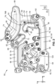
- FIGS 2 to 4 show a fluid distribution module 50 for a thermal management system.
- the thermal management system is in particular installed in a motor vehicle (not illustrated).
- the motor vehicle is preferably an electric vehicle or a hybrid vehicle, but it could also be an internal combustion engine vehicle.
- the fluid distribution module 50 is configured to distribute in the thermal management system at least one heat transfer fluid.
- Heat transfer fluid is understood herein as a fluid capable of absorbing calories or frigories from at least one component of the thermal management system. As it will be detailed, several heat transfer fluids having or not the same composition but having different temperatures can travel in different zones of the module 50.
- the fluid distribution module 50 is for example a refrigerant distribution module. Alternatively, the fluid distribution module 50 could be a coolant distribution module.
- the module 50 comprises a plurality of channels 52.
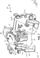
- the channels 52 are for example formed by fixing a first plate 54 to a second plate 55, shown in figure 4 .
- the second plate 55 faces the first plate 54 in the Z-axis.
- the first plate 54 comprises a plurality of tracks 56.
- a flat part 58 is arranged between the tracks 56.
- the flat part 58 is comprised in a first plane P1 substantially parallel to a X-Y plane (i.e., a plane comprising the X-axis and the Y-axis).
- each track 56 protrudes with respect to the flat part 58 along the Z-axis.
- each track 56 is delimited by a wall 57 that can protrude with respect to the flat part 58 along the Z-axis.
- the wall 57 of each of the tracks 56 has a concave cross-section in a plane substantially perpendicular to the first plane P1.
- the flat portion 58 is essentially flat. Nevertheless, it could also comprise one or more reinforcement rib(s) (not shown in the figures) protruding along the Z-axis with respect to the rest of the flat portion 58. In that case, each rib surrounds one or more tracks 56 and allows to increase the stiffness of the module 50.
- the module 50 further comprises at least one connector 62 connected to the first plate 54.
- each connector 62 may be integrally formed with the first plate 54.
- Each connector 62 is shaped to form a fixing point of a component of the thermal management system to the module 50 from which the heat transfer fluid comes or to which the heat transfer fluid is directed.
- the component of the thermal management system can be, for example, a compressor, refrigerant bottles, heat exchangers such as an evaporator and/or a chiller and/or a water chiller, and/or a condenser, valves, sensors, etc.
- At least one of the connectors 62 is arranged on a track 56 and forms a hollow cavity that traverses in its entirety the wall 57 of the corresponding track 56.
- Such a connector 62 constitutes a first heat transfer fluid passage 63.
- the component of the thermal management system can therefore be fixed to said passage 63, so that the heat transfer fluid can travel between said component and the module 50.
- each heat transfer fluid passage 63 forms a first angle A1 comprised between 70° and 110° with the first plate 54.
- the first angle A1 is for example substantially equal to 90°.
- Each first heat transfer fluid passage 63 is fluidically connected to at least one of the channels 52, so that the heat transfer fluids can travel between the heat transfer fluid passage 63 and the corresponding channel 52.
- the heat transfer fluid passage 63 can be a heat transfer fluid inlet and/or a heat transfer fluid outlet of the module 50.
- Each passage 63 comprises a bend 67 connected to the first plate 54.
- the bend 67 has a substantially curved surface.
- a radius of curvature of said bend is comprised between 1 mm and 15 mm.
- Such a bend radius R1 range makes it possible to reduce the turbulences created at the interface between the passage 63 and the channel 52 to which the passage 63 is fluidically connected.
- the bend radius R1 is comprised between 5 mm and 10 mm.
- the bend radius R1 is bigger than 5 mm. The larger the bend radius R1, the more turbulences at the interface between the passage 63 and the corresponding channel 52 are reduced.
- the second plate 55 is essentially flat and is comprised in a second plane P2 substantially parallel to the first plane P1.
- the second plate 55 defines therefore a principal plane corresponding to the second plane P2.
- the second plate 55 has some tracks identical or similar to the tracks 56 of the first plate 54 but protruding in an opposite direction along the Z-axis.
- some connectors 62 can also be connected to the second plate 55.
- the connectors 62 can be formed integrally with the second plate 55.
- Some of the connectors 62 of the second plate 55 can form a second heat transfer fluid passage 65 identical or similar to the first heat transfer fluid passage 63 described above.
- each second heat transfer fluid passage 65 is fluidically connected to one of the channels 52 of the module 50.
- Each second heat transfer fluid passage 65 forms therefore a heat transfer fluid inlet and/or a heat transfer fluid outlet of the fluid distribution module 50.
- each second heat transfer fluid passage 65 comprises a bend identical or similar to the bend 67 of each passage 63 described above but connected to the second plate 55.
- the second plate 55 comprises at least a first pocket 110.
- Each first pocket 110 is advantageously placed opposite to one of the first heat transfer fluid passages 63.
- the first plate 54 can comprise at least a second pocket, referenced 120 in figures 2 and 3 .
- Each second pocket 120 is advantageously placed opposite to one of the second heat transfer fluid passages 65.
- first pocket 110 and second pocket 120 will be described later with reference to figures 5 and 6 .
- the first plate 54 and the second plate 55 are sealed together, for example by welding.
- the channels 52 are formed in the space comprised between the tracks 56 of either the first plate 54 and the second plate 55, and the other plate.
- each of the first and the second plates 54, 55 are made of metal, for example of aluminum.
- each of the first and the second plates 54, 55 are made of polymer, for example of polypropylene.
- the module 50 distributes in the thermal management system at least one heat transfer fluid, for example a refrigerant or a coolant.
- the module 50 may comprise a first zone 64, a second zone 66 and a third zone 68.
- Each zone 64, 66, 68 comprise at least one channel 52 in which the corresponding heat transfer fluid flows.
- the first zone 64 and the second zone 66 comprise a single channel 52, while the third zone 68 comprise two channels 52.
- the heat transfer fluid may flow at a first temperature.
- the first temperature ranges from -15°C to 15°C, preferably from -10°C to 10°C.
- the first zone 64 is therefore for example a low temperature zone.
- the heat transfer fluid may flow at a low pressure.
- Low pressure is understood here as a pressure comprised between 0.1 bar and 8 bar, preferably between 0.5 bar and 6.5 bar. This low pressure is generally accompanied of a low speed of the heat transfer fluid.
- the heat transfer fluid may be advantageously a gaseous fluid.
- the heat transfer fluid may flow at a second temperature that is higher than the first temperature in the first zone 64.
- the second temperature ranges from 70°C to 130°C.
- the second zone 66 is therefore for example a high temperature zone.
- the heat transfer fluid may flow at a high pressure.
- "High pressure” is understood here as a pressure comprised between 9 bar and 30 bar, preferably between 10 bar and 26 bar. This low pressure is generally accompanied of a high speed of the heat transfer fluid.
- the heat transfer fluid may be advantageously a gaseous fluid.
- the heat transfer fluid may flow at a third temperature that is different than the first temperature in the first zone 64 and the second temperature in the second zone 66.
- the third temperature ranges from 25°C to 50°C, preferably from 25°C to 45°C.
- the third zone 68 is therefore for example a medium temperature zone.
- the heat transfer fluid may flow at high pressure (as defined above).
- the heat transfer fluid can be a gaseous fluid and/or a liquid fluid.
- the heat transfer fluid can be in the liquid state while in the other channel 52 the heat transfer fluid can be in the gaseous state.
- the heat transfer fluids flowing in the first zone 64, the second zone 66 and the third zone 68 can have the same composition or a different composition.
- the heat transfer fluids flowing in each channel 52 of the same zone can have the same composition or a different one.
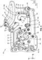
- the three zones 64, 66, 68 are directly connected to each other.
- the first zone 64 and the second zone 66 are separated by a first gap 78A
- the third zone 68 is separated from the first zone 64 and the second zone 66 by a second gap 78B.
- the first gap 78A and the second gap 78B can be integrally formed, so that they form a single gap 78.
- the gaps 78, 78A and 78B are zones directly between the first zone 64 and at least one of the second zone 66 and the third zone 68 in which there is no material part of the module 50.
- the gaps 78, 78A and 78B may be delimited by part of an edge 79 of the fluid distribution module 50 that forms an open loop.
- the gaps 78, 78A, 78B may comprise an opening 80. This allows the module 50 to have a certain flexibility that allows the module 50 to move locally if for example a chiller or a heat exchanger to which it is connected thermally expands. Mechanical stresses in the module 50 are therefore limited. Thermal dilatation or contraction of the module 50 is thus possible while limiting the mechanical stresses.
- first zone 64 can form a first tongue 70
- second zone 66 can form a second tongue 72
- third zone 68 can form a third tongue 74
- a tongue is defined herein as a portion of each zone 64, 66, 68 that is directly connected to the rest of the module 50 but mostly not surrounded by the material of the module 50.
- a tongue may be a portion of each zone that includes only a joining line with the rest of the module 50, such joining line being, for example, substantially parallel to a single straight direction.
- the tongues 70, 72 and 74 of figure 2 are surrounded by the first gap 78A, the second gap 78B and/or the outside of the fluid distribution module 50.
- Each zone 64, 66, 68 can comprise at least one connector 62 forming a first heat transfer fluid passage 63 or a second heat transfer fluid passage 65 as described above.
- At least one connector 62 can be arranged on the first tongue 70, the second tongue 72 and the third tongue 74.
- the at least one connector 62 arranged on the first tongue 70, the second tongue 72 and the third tongue 74 may form a first heat transfer fluid passage 63 or a second heat transfer fluid passage 65.
- Each tongue 70, 72, 74 form an elastic area of the module 50.
- elastic area it is understood an area that has a certain level of flexibility and movement with respect to the rest of the module. The level of flexibility and movement depends on the design of tongues and the elastic module of the material. In the parts of the module 50 that tongues 70, 72, 74 are not included, stiff areas 82 are formed, as shown in figure 3 .
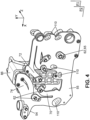
- the elastic areas it is possible to connect to the module 50 a component, referenced 86 in figure 4 , of the thermal management system as those presented previously, the module 50 being able to follow the eventual movement of this component when it changes its volume due to thermal expansion or contraction. This limits the occurrence of mechanical stresses in the distribution module 50.
- the stiff areas 82 allow that the module 50 forms a unit frame 100 with at least one bracket 90.
- the at least one bracket 90 is fixed to the stiff areas 82 of the module 50.
- two brackets 90 are provided.
- the module 50 and each bracket 90 can be fixed either by a fixed connection or by a permanent joint.
- the at least one bracket 90 is provided with at least one decoupling element 91 received in a groove 92 formed in the respective bracket 90.
- the decoupling elements can be of any suitable kind (foam, rubber, ).
- the decoupling element 91 ensures a vibrational decoupling of the thermal management system from the vehicle body. Hence, the propagation of acoustic waves and vibrations from the thermal management system to the cabin of the vehicle is reduced, which improves the comfort of the passengers.
- Forming a unit frame UF allow that the thermal management system can be handled as one piece, which is convenient for installing or uninstalling the thermal management system in the vehicle.
- brackets their position and shape depend on the number of components of the thermal management system.
- the stiff areas 82 of the module 50 to which the brackets 90 are fixed correspond to low temperature zones. This avoids the occurrence of mechanical stresses in the brackets due to thermal expansion of the module 50.
- One of the first pockets 110 is now described with reference to figure 5 .
- the first pocket 110 is comprised in the second plate 55 and placed opposite to one of the first heat transfer fluid passages 63. As shown in figure 5 , the first pocket 110 joins the passage 63 with the second plate 55.
- the first pocket 110 is substantially concave. As shown in figure 5 , the first pocket 110 protrudes with respect to the second plane P2.
- the pocket 110 has an oval shape, but any other shape is possible.
- the shape and size of the pocket 110 can be adapted to the pressure and phase (liquid/gas) of the heat transfer fluid circulating inside the channel 52 to which the passage 63 is fluidically connected.
- the first pocket 110 may be smaller than when the heat transfer fluid is in the gas phase.
- the size of the pocket 110 may be intermediate between the size of the first pocket 110 when the heat transfer fluid is in the liquid phase and in the gas phase.
- the shape and size of the pocket 110 can be adapted to the shape of channel 52 to which the passage 63 is fluidically connected.
- a radius of curvature of the first pocket 110 is comprised between 20 mm and 50 mm, preferably between 30 mm and 40 mm.
- the first pocket 110 is formed integrally with the second plate 55, for example by stamping. In other cases, the first pocket 110 is formed by a separate piece, having a concave shape, that is attached to a through hole formed in the second plate 55.
- FIG 6 shows an example of second pocket 120.
- the description of the first pocket 110 above is applicable to any the second pocket 120. Therefore, for the sake of conciseness, the second pocket 120 is not described in detail hereinafter, but only the differences from the first pocket 110 are detailed.
- the second pocket 120 differs from the first pocket 110 in that the second pocket 120 is comprised in the first plate 54 and placed opposite to one of the second heat transfer fluid passages 65.
- the second pocket 120 therefore joins the passage 65 with the first plate 54 and protrudes with respect to the first plate P1.
- the rest of the features of the first pocket 110 are applicable to the second pocket 120.
- the heat transfer fluid entering or leaving the module 50 through the passage 63 or the passage 65 has more space to turn, so that rotations of the heat transfer fluid of about 90° are avoided.
- the heat transfer fluid therefore flows more smoothly, and the occurrence of turbulences at the interface between the passage 63 or the passage 65 and the channel 52 to which the respective passage 63, 65 is fluidically connected is limited. Consequently, the pressure of the heat transfer fluid in the module 50 is reduced, each passage 63, 65 forming a pressure drop zone of the module 50.
- the noise generated by the circulation of the heat transfer fluid in the fluid distribution module 50 is reduced. This reduction of noise is particularly important when the module 50 is attached to the vehicle chassis.
- the heat transfer fluid move in the module 50 with less energy and speed, so that energy consumption in the module 50 is minimized.
- first plate 54 and the second plate 55 comprising the tracks 56 and the connectors 62, but without first pockets 110 and second pockets 120 are obtained.
- each first pocket 110 and, eventually, each second pocket 120 are formed respectively in the second plate 55 and in the first plate 54 by stamping the corresponding plate 54, 55.
- stamping is meant a process comprising applying a pressure on the corresponding plate 54, 55 to create thereon a concavity suitable to form a pocket 110, 120 as described below.
- first plate 54 and the second plate 55 are sealed together.
- first plate 54 is arranged opposite to the second plate 55 to form the plurality of channels 52, each passage 63 being placed opposite to one first pocket 110.
- second plate 55 comprises a passage 65
- first plate comprises a second pocket 120
- the first plate 54 and the second plate 55 are sealed together so that each passage 65 is opposite to one of the second pockets 120.
- the method first comprises making at least one through hole in, respectively, the second plate 55 and/or in the first plate 54. Then, the separated concave piece is attached to each through hole of second plate 55 and/or of the first plate 54 to form the first pocket 110 and/or the second pocket 120. Finally, the first plate 54 and the second plate 55 are sealed together as explained above.
Landscapes
- Engineering & Computer Science (AREA)
- Mechanical Engineering (AREA)
- General Engineering & Computer Science (AREA)
- Physics & Mathematics (AREA)
- Thermal Sciences (AREA)
- Chemical & Material Sciences (AREA)
- Combustion & Propulsion (AREA)
- Transportation (AREA)
- Heat-Exchange Devices With Radiators And Conduit Assemblies (AREA)
Priority Applications (3)
| Application Number | Priority Date | Filing Date | Title |
|---|---|---|---|
| EP23175707.1A EP4467366A1 (de) | 2023-05-26 | 2023-05-26 | Fluidverteilungsmodul für ein wärmeverwaltungssystem |
| PCT/EP2024/064535 WO2024246007A1 (en) | 2023-05-26 | 2024-05-27 | Fluid distribution module for a thermal management system |
| CN202480034934.9A CN121263316A (zh) | 2023-05-26 | 2024-05-27 | 用于热管理系统的流体分配模块 |
Applications Claiming Priority (1)
| Application Number | Priority Date | Filing Date | Title |
|---|---|---|---|
| EP23175707.1A EP4467366A1 (de) | 2023-05-26 | 2023-05-26 | Fluidverteilungsmodul für ein wärmeverwaltungssystem |
Publications (1)
| Publication Number | Publication Date |
|---|---|
| EP4467366A1 true EP4467366A1 (de) | 2024-11-27 |
Family
ID=86605060
Family Applications (1)
| Application Number | Title | Priority Date | Filing Date |
|---|---|---|---|
| EP23175707.1A Pending EP4467366A1 (de) | 2023-05-26 | 2023-05-26 | Fluidverteilungsmodul für ein wärmeverwaltungssystem |
Country Status (3)
| Country | Link |
|---|---|
| EP (1) | EP4467366A1 (de) |
| CN (1) | CN121263316A (de) |
| WO (1) | WO2024246007A1 (de) |
Citations (4)
| Publication number | Priority date | Publication date | Assignee | Title |
|---|---|---|---|---|
| US20010020786A1 (en) * | 2000-02-24 | 2001-09-13 | Yoshikazu Takamatsu | Joint for duplex pipes, method of brazing the joint to duplex pipe, and air conditioning apparatus for vehcile |
| US20170324132A1 (en) * | 2016-05-06 | 2017-11-09 | Dana Canada Corporation | Heat Exchangers For Battery Thermal Management Applications With Integrated Bypass |
| WO2021048095A1 (de) * | 2019-09-09 | 2021-03-18 | Brose Fahrzeugteile SE & Co. Kommanditgesellschaft, Würzburg | Kompaktmodul zur temperierung eines kraftfahrzeugs |
| CN112543712A (zh) * | 2018-01-29 | 2021-03-23 | 沃克工业技术有限公司 | 用于处理流体的设备及其制造方法 |
-
2023
- 2023-05-26 EP EP23175707.1A patent/EP4467366A1/de active Pending
-
2024
- 2024-05-27 CN CN202480034934.9A patent/CN121263316A/zh active Pending
- 2024-05-27 WO PCT/EP2024/064535 patent/WO2024246007A1/en active Pending
Patent Citations (4)
| Publication number | Priority date | Publication date | Assignee | Title |
|---|---|---|---|---|
| US20010020786A1 (en) * | 2000-02-24 | 2001-09-13 | Yoshikazu Takamatsu | Joint for duplex pipes, method of brazing the joint to duplex pipe, and air conditioning apparatus for vehcile |
| US20170324132A1 (en) * | 2016-05-06 | 2017-11-09 | Dana Canada Corporation | Heat Exchangers For Battery Thermal Management Applications With Integrated Bypass |
| CN112543712A (zh) * | 2018-01-29 | 2021-03-23 | 沃克工业技术有限公司 | 用于处理流体的设备及其制造方法 |
| WO2021048095A1 (de) * | 2019-09-09 | 2021-03-18 | Brose Fahrzeugteile SE & Co. Kommanditgesellschaft, Würzburg | Kompaktmodul zur temperierung eines kraftfahrzeugs |
Also Published As
| Publication number | Publication date |
|---|---|
| CN121263316A (zh) | 2026-01-02 |
| WO2024246007A1 (en) | 2024-12-05 |
Similar Documents
| Publication | Publication Date | Title |
|---|---|---|
| JP2024508569A (ja) | 熱管理統合モジュール及び電気自動車 | |
| US8789805B2 (en) | Vibration stabilization system for multi-cooler | |
| EP4613514A1 (de) | Wärmeverwaltungssystem für ein fahrzeug und fahrzeug | |
| JP2024512150A (ja) | 弁群統合モジュール及びそれを有する車両 | |
| CN101384444A (zh) | 具有蓄冷器的热交换器 | |
| US12083866B2 (en) | Integrated refrigerant control modules | |
| CN218661268U (zh) | 空调系统及其内部换热器、整车热管理系统、车辆 | |
| JP2016526145A (ja) | 接続モジュール、熱交換器、および対応する熱交換アセンブリ | |
| US12235051B2 (en) | Pipe arrangement for transporting temperature control media | |
| WO2024093590A1 (zh) | 空调系统及其内部换热器、整车热管理系统、车辆 | |
| US20140048238A1 (en) | Frameless Heat Exchanger | |
| EP4467366A1 (de) | Fluidverteilungsmodul für ein wärmeverwaltungssystem | |
| JP2022001427A (ja) | 温度制御媒体の輸送用管路装置の製造方法 | |
| EP4417926A1 (de) | Fluidverteilungsmodul für ein wärmeverwaltungssystem | |
| CN113678303A (zh) | 冷却装置以及壳体 | |
| CN116782585B (zh) | 用于热交换器的入口和出口通道 | |
| CN1910420B (zh) | 热交换装置系统 | |
| US12330473B2 (en) | Integrated stacked heat exchangers | |
| CN218661236U (zh) | 整车热管理系统、车辆 | |
| EP0869325A2 (de) | In Reihen integrierte Wärmetauscher | |
| EP3543550B1 (de) | Wärmetauscher | |
| CN120018958A (zh) | 热管理模块和具有至少一个该热管理模块的车辆 | |
| CN117227455A (zh) | 热管理集成模块、热管理系统及车辆 | |
| KR101170610B1 (ko) | 축냉 열교환기 | |
| EP4335671A1 (de) | Fluidmanagementmodul für ein fahrzeug |
Legal Events
| Date | Code | Title | Description |
|---|---|---|---|
| PUAI | Public reference made under article 153(3) epc to a published international application that has entered the european phase |
Free format text: ORIGINAL CODE: 0009012 |
|
| STAA | Information on the status of an ep patent application or granted ep patent |
Free format text: STATUS: THE APPLICATION HAS BEEN PUBLISHED |
|
| AK | Designated contracting states |
Kind code of ref document: A1 Designated state(s): AL AT BE BG CH CY CZ DE DK EE ES FI FR GB GR HR HU IE IS IT LI LT LU LV MC ME MK MT NL NO PL PT RO RS SE SI SK SM TR |
|
| STAA | Information on the status of an ep patent application or granted ep patent |
Free format text: STATUS: REQUEST FOR EXAMINATION WAS MADE |
|
| 17P | Request for examination filed |
Effective date: 20250520 |