EP4467288A2 - Tool bit having a bimetal tip - Google Patents
Tool bit having a bimetal tip Download PDFInfo
- Publication number
- EP4467288A2 EP4467288A2 EP24205179.5A EP24205179A EP4467288A2 EP 4467288 A2 EP4467288 A2 EP 4467288A2 EP 24205179 A EP24205179 A EP 24205179A EP 4467288 A2 EP4467288 A2 EP 4467288A2
- Authority
- EP
- European Patent Office
- Prior art keywords
- segment
- stock
- connection interface
- tool bit
- end portion
- Prior art date
- Legal status (The legal status is an assumption and is not a legal conclusion. Google has not performed a legal analysis and makes no representation as to the accuracy of the status listed.)
- Pending
Links
Images

Classifications
-
- B—PERFORMING OPERATIONS; TRANSPORTING
- B25—HAND TOOLS; PORTABLE POWER-DRIVEN TOOLS; MANIPULATORS
- B25B—TOOLS OR BENCH DEVICES NOT OTHERWISE PROVIDED FOR, FOR FASTENING, CONNECTING, DISENGAGING, OR HOLDING
- B25B15/00—Screwdrivers
- B25B15/001—Screwdrivers characterised by material or shape of the tool bit
-
- B—PERFORMING OPERATIONS; TRANSPORTING
- B25—HAND TOOLS; PORTABLE POWER-DRIVEN TOOLS; MANIPULATORS
- B25B—TOOLS OR BENCH DEVICES NOT OTHERWISE PROVIDED FOR, FOR FASTENING, CONNECTING, DISENGAGING, OR HOLDING
- B25B15/00—Screwdrivers
- B25B15/001—Screwdrivers characterised by material or shape of the tool bit
- B25B15/002—Screwdrivers characterised by material or shape of the tool bit characterised by material used or surface finishing
-
- B—PERFORMING OPERATIONS; TRANSPORTING
- B25—HAND TOOLS; PORTABLE POWER-DRIVEN TOOLS; MANIPULATORS
- B25B—TOOLS OR BENCH DEVICES NOT OTHERWISE PROVIDED FOR, FOR FASTENING, CONNECTING, DISENGAGING, OR HOLDING
- B25B15/00—Screwdrivers
- B25B15/001—Screwdrivers characterised by material or shape of the tool bit
- B25B15/004—Screwdrivers characterised by material or shape of the tool bit characterised by cross-section
- B25B15/005—Screwdrivers characterised by material or shape of the tool bit characterised by cross-section with cross- or star-shaped cross-section
-
- B—PERFORMING OPERATIONS; TRANSPORTING
- B25—HAND TOOLS; PORTABLE POWER-DRIVEN TOOLS; MANIPULATORS
- B25B—TOOLS OR BENCH DEVICES NOT OTHERWISE PROVIDED FOR, FOR FASTENING, CONNECTING, DISENGAGING, OR HOLDING
- B25B23/00—Details of, or accessories for, spanners, wrenches, screwdrivers
- B25B23/0007—Connections or joints between tool parts
- B25B23/0035—Connection means between socket or screwdriver bit and tool
Definitions
- the present disclosure relates to tool bits and, more particularly, to tool bits being composed of multiple materials.
- a tool bit in one aspect, includes a drive portion configured to be selectively coupled to a tool.
- the drive portion is composed of a first material.
- the tool bit also includes a shank coupled to the drive portion.
- the shank is composed of the first material.
- the tool bit includes a working end portion having a first segment and a second segment.
- the first segment is coupled to the shank and being composed of the first material.
- the second segment is fixed to the first segment at a connection interface.
- the second segment is composed of a second material different than the first material.
- the second segment is configured to engage a fastener for the working end portion to drive the fastener.
- a tool bit in another aspect, includes a drive portion configured to be selectively coupled to a tool.
- the drive portion is composed of a first material.
- the tool bit includes a working end portion having a shape configured to correspond with a recess of a fastener for the working end portion to engage and drive the fastener.
- the working end portion includes a first segment and a second segment. The first segment is located between the second segment and the drive portion. The first segment is composed of the first material. The second segment is fixed to the first segment at a connection interface. The second segment is composed of a second material different than the first material.
- a method of manufacturing a tool bit includes providing a first stock of material composed of a first material, providing a second stock of material composed of a second material different than the first material, fixing the first stock of material and the second stock of material together to form a connection interface, determining a length of the second stock of material extending from the connection interface, shaping the first stock of material to form a first segment of a working end portion, and shaping the second stock of material based on the determined length to form a second segment of the working end portion.
- the second segment is configured to engage a fastener for the working end portion to drive the fastener.
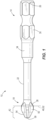
- FIGS. 1 and 2 illustrate a tool bit 10 for use with a tool (e.g., a power tool and/or a hand tool).
- the illustrated tool bit 10 includes a tool body having an insertion end portion 14 (e.g., a hexagonal drive portion), a working end portion 18, and a connection portion 22 (e.g., a shank) extending between the working end portion 18 and the insertion end portion 14.
- a tool body e.g., a hexagonal drive portion
- connection portion 22 e.g., a shank
- the insertion end portion 14 is configured to be connected to the tool. More particularly, the insertion end portion 14 is configured to be inserted into and received by a bit holder, chuck, or other structure coupled to or part of the tool. For ease of discussion, all of these types of structures will be referred to as bit holders herein.
- the insertion end portion 14 defines a first end 26 of the tool body that is opposite the working end portion 18.
- the insertion end portion 14 is composed of a first material.
- An outer surface on the insertion end portion 14 is at least partially defined by a non-circular profile 30. In the illustrated embodiment, the non-circular profile 30 is a hexagonal or hex-shaped profile configured to be received in a hexagonal or hex-shaped bit holder.
- the non-circular profile 30 may be other suitable profiles, such as D-shaped, flattened, oblong, triangular, square, octagonal, star-shaped, irregular, and the like.
- a portion of the outer surface on the insertion end portion 14 not defined by the non-circular profile 30 is defined by a circular profile 34.
- the circular profile 34 may be another profile, such as square, octagonal, star-shaped, irregular, and the like, or the circular profile 34 may be omitted.
- the circular profile 34 is proximate the connection portion 22.
- connection portion 22 is positioned between the working end portion 18 and the insertion end portion 14 (e.g., between the working end portion 18 and the circular profile 34).
- the connection portion 22 includes a circular cross-sectional shape and defines a maximum radial dimension R3 (e.g., a maximum radius; FIG. 2 ) relative to a longitudinal axis of the tool bit 10.
- R3 a maximum radial dimension
- the connection portion 22 may define a cross-sectional shape that is rectangular, octagonal, star-shaped, and the like.
- the connection portion 22 is also composed of the first material.
- the working end portion 18 is configured to engage with a fastener (e.g., a screw). More particularly, the working end portion 18 is configured to drive the fastener into a workpiece.
- the working end portion 18 includes a first segment 38 (e.g., a rearward segment) separated from a second segment 42 (e.g., a forward segment) by a connection interface 46.
- the connection interface 46 defines a maximum radial dimension R2 (e.g., a maximum radius) relative to the longitudinal axis of the tool bit 10.
- R2 e.g., a maximum radius
- a cross-section of the working end portion 18 at the maximum radius R2 defines a cross.
- the maximum radius R2 is measured relative to a circle circumscribed by the cross.
- the cross-section may define a rectangle, an oval, a star, and the like.
- the illustrated forward segment 42 is composed of a second material and includes a first portion 50 and a second portion 54.
- the second portion 54 includes a second end 58 (e.g., a tip) of the tool body that is opposite the first end 26.
- the second portion 54 of the working end portion 18 is the portion of the tool bit 10 that is inserted into a recess of the fastener when the tool bit 10 engages and drives the fastener.
- the second portion 54 can be referenced as a fastener engagement portion.
- the working end portion 18 is inserted into the fastener up to a depth measured from the second end 58 (e.g., the axial distance between the second end 58 and the interface between the first and second portions 50, 54).
- a depth measured from the second end 58 e.g., the axial distance between the second end 58 and the interface between the first and second portions 50, 54.
- an outer surface of the working end portion 18 defines a maximum radial dimension R1 (e.g., a maximum radius; FIG. 2 ) relative to the longitudinal axis of the tool bit 10.
- a cross-section of the working end portion 18 at the maximum radius R1 also defines a cross.
- the maximum radius R1 is measured relative to a circle circumscribed by the cross.
- the cross-section may define a rectangle, an oval, a star, and the like.
- the radius R2 is larger than the radius R1. Additionally, the radius R1 and the radius R2 are both larger than the radius R3. Furthermore, a distance from the second end 58 to the location of the maximum radius R1 is less than a distance from the second end 58 to the location of the connection interface 46.
- the working end portion 18 is composed of the first material and the second material.
- the second material defines the second segment 42 (e.g., the first and second portions 50, 54), and the first material defines a remainder of the working end portion 18 (e.g., the first segment 38) not defined by the second material.
- the second material has a hardness that is greater than a hardness of the first material.
- the second segment 42 is harder than the first segment 38.
- the hardness of the second material is at least 5% greater than the hardness of the first material. In other embodiments, the hardness of the second material is between 5% and 30% greater than the hardness of the first material.
- the first material is a tool steel.
- the first material may be a low carbon steel, such as AISI 1018.
- AISI 1018 low carbon steel includes a balance of toughness, strength, and ductility.
- AISI 1018 low carbon steel includes approximately 0.14% to 0.2% carbon and 0.6% to 0.9% manganese.
- the first material may be a high carbon steel, such as AISI 1065.
- AISI 1065 high carbon steel includes a high tensile strength.
- AISI high carbon steel includes approximately 0.6% to 0.7% carbon and 0.6% to 0.9% manganese.
- the first material may be an alternative material.
- the tool steel may have a hardness, for example between about 45 HRC and about 60 HRC. In some embodiments, the tool steel may have a hardness of between about 45 HRC and about 55 HRC.
- the second material is a high speed steel (HSS), such as PM M4.
- HSS high speed steel
- PM M4 high speed steel includes a fine grain size, small carbides, and a high steel cleanliness, which together provide high wear-resistance, high impact toughness, and high bend strength.
- PM M4 high speed steel includes approximately 1.4% carbon, 4% Chromium, 5.65% tungsten, 5.2% molybdenum, and 4% vanadium.
- the second material may be an alternative material (e.g., carbide).
- the high speed steel may have a hardness, for example, of 60 HRC or greater.
- the cost to manufacture the tool bit 10 is minimized while the strength of the tool bit 10 is maintained.
- the cost to manufacture the tool bit 10 is minimized due to the material being used for the first material generally being inexpensive.
- the second material compensates for a lower strength of the first material.
- FIG. 3 illustrates a method 62 of manufacturing the tool bit 10. Although the illustrated method 62 includes specific steps, not all of the steps need to be performed. In addition, the depicted steps do not need to be performed in the order presented. The method 62 may also include additional or alternative steps.
- the illustrated method 62 includes providing a first stock of material (step 66) composed of the first material and providing a second stock of material (step 70) composed of the second material.
- Step 74 includes fixing the first stock of material to the second stock of material (e.g., the forward segment 42 composed of the second material is secured to the rearward segment 38 composed of the first material).
- the segments 38, 42 are fixed together at the connection interface 46.
- the segments 38, 42 are fixed together by a welding process.
- the first and second stocks of material may be welded via spin welding, resistance welding, laser welding, friction welding, and the like.
- the segments 38, 42 are fixed together by a different process (e.g., a brazing process or the like).
- the first stock of material is a hex-shaped blank and the second stock of material is a cylinder-shaped blank.
- the first and second stocks of material may differ in shape.
- An axial length of the second stock of material extending from the connection interface 46 is determined (step 78) as discussed in more detail below.
- the first stock of material and the second stock of material may then be machined or shaped (steps 82, 86) to form the tool bit 10.
- Shaping the second stock of material (step 86) is based on the determined length (step 78) of the second stock of material.
- the first stock of material forms the first end 26 to the connection interface 46, and the second stock of material forms the second end 58 to the connection interface 46.
- the first stock of material is shaped to form the insertion end portion 14, the connection portion 22, and the rearward portion 38.
- the second stock of material is shaped to form the working end portion 18 from the second end 58 to the connection interface 46 (e.g., the forward segment 42).
- the method 62 can be different (e.g., the axial length of the second stock can be determined before the first and second stock of material are fixed together).
- the torsional stress ⁇ R 1 is calculated at the radius R1.
- the torsional stress ⁇ R 1 is related to an applied torque T R 1 , the radius R1 that the stress is occurring at, and a polar moment of inertia of the cross section J T R1 at the radius R1.
- the torsional stress ⁇ R 1 at the radius R1 is expressed in Equation 1.
- ⁇ R 1 T R 1 ⁇ R1 J T R 1
- the torsional stress ⁇ R 2 allowed at the radius R2 may then be calculated based on the torsional stress ⁇ R 1 at the radius R1.
- the torsional stress ⁇ R 2 allowed at the radius R2 is a percentage P of the torsional stress ⁇ R 1 at the radius R1.
- the percentage P is based on the difference in hardness between the first material and the second material. For example, if the first material was 80% the hardness of the second material, the torsional stress ⁇ R 2 allowed at the radius R2 would be 80% the torsional stress ⁇ R 1 at the radius R1.
- the torsional stress ⁇ R 2 allowed at the radius R2 is expressed in Equation 2.
- ⁇ R 2 P ⁇ T R 1 ⁇ R1 J T R 1
- the torsional stress ⁇ R 2 allowed at the radius R2 may be related to the applied torque T R 2 , the radius R2, and a polar moment of inertia of the cross section J T R2 at the radius R2.
- the torsional stress ⁇ R 2 allowed at the radius R2 is expressed in Equation 3.
- ⁇ R 2 T R 2 ⁇ R2 J T R 2
- connection interface 46 may be selected such that the ratio of the radius R2 to the polar moment of the cross section J T R2 at the radius R2 is less than or equal to the ratio of the radius R1 to the polar moment of the cross section J T R1 at the radius R1 multiplied by the percentage P difference between the hardnesses of the first material and the second material.
- connection interface 46 may be selected in view of both Equation 5 and Equation 4.
- the ratio of the radius R2 to the polar moment of the cross section J T R2 at the radius R2 is additionally less than or equal to the ratio of the radius R3 to the polar moment of the cross section J T R3 at the radius R3 multiplied by the percentage P difference between the hardnesses of the first material and the second material.
- An axial distance of the connection interface 46 from the second end 58 may be determined (step 78) based on the ratio of the radius R2 to the polar moment of the cross section J T R2 at the radius R2.
- a radius and a polar moment may be calculated along a length of the working end portion 18 to determine where the correct ratio occurs.
- the axial distance of the connection interface 46 of a square tip tool bit 10 is based on the ratio of the radius R2 to the polar moment of the cross section J T R2 at the radius R2, as depicted in the table below.
- the hardness of the first material is 80% of the hardness of the second material, and the engagement distance (i.e., the location of the maximum radius R1) is about 0.08 inches from the second end 58.
- the ratio of the radius R1 to the polar moment of the cross section J T R1 at the radius R1 is 2614.5.
- 80% of 2614.5 is 2091.6, which is the target ratio for R2.
- the calculated ratio for radius R2 to the polar moment of the cross section J T R2 at the radius R2 is equal to or less than 2091.6 when the distance from the second end 58 is 0.16 inches.
- connection interface 46 between the first material and the second material for a size #2 square bit should be at about 0.16 inches from the second end 58.
- Distance from the second end (inches) Polar Moment of Inertia of the cross section Radius (inches) R 2 J T R 2 0.08 0.00003117 0.081496 2614.567 0.1 0.00003328 0.083071 2496.12 0.12 0.00003608 0.084646 2346.055 0.14 0.00004029 0.08622 2139.997 0.16 0.00004613 0.087795 1903.214
- Determining the axial distance of the connection interface 46 of the #2 square bit can be applied to different sizes and/or types of bits 10.
- the table below provides some examples of different sizes and types of bits 10 and maintains that the hardness of the first material is 80% of the hardness of the second material.
- the first column in the table below represents the type and size of the bit 10 (e.g., PH1 is a size #1 Phillips-head bit, PZ1 is a size #1 Pozidriv-head bit, SQ1 is a size #1 square-head bit, and T10 is a size #10 Torx-head bit).
- the number associated with the type/geometry of the bit represents the standard size of the bit head.
- the table below shows, for example, the axial distance of the connection interface 46 of a size #1 Phillips-head bit relative to the tip 58 is about 0.087 inches.
- a typical axial distance between the tip 58 and the radius R1 e.g., a depth at which a #1 Phillips-head bit is received within a fastener
- the polar moment of the cross section J T R1 at radius R1 is 0.00000840 and radius R1 is 0.058544 inches, such that a ratio of the radius R1 to the polar moment of the cross section J T R1 at the radius R1 is 6969.524.
- 80% of 6969.524 is about 5575.62, which is the target ratio for R2.
- the calculated ratio for radius R2 to the polar moment of the cross section J T R2 at the radius R2 is equal to or less than 5575.62 when the distance from the second end 58 is about 0.087 inches.
- the connection interface 46 between the first material and the second material for a size #1 Phillips-head bit should be at about 0.087 inches from the second end 58. Similar calculations can be performed for the other types of tool bits 10 within the table below.
- a T15 bit includes a distance between the connection interface 46 and the tip 58 of about 0.12 inches with a fastener engagement depth of about 0.07 inches
- a T25 bit includes a distance between the connection interface 46 and the tip 58 of about 0.16 inches with a fastener engagement depth of about 0.1 inches
- a T27 bit includes a distance between the connection interface 46 and the tip 58 of about 0.175 inches with a fastener engagement depth of about 0.11 inches.
- welding the first material to the second material may create a heat affect zone 90.
- the heat affect zone 90 has a lower material strength than a material strength of the second material.
- a distance at which the heat affect zone 90 has affected the second material is added to the axial distance of the original connection interface 46a to offset a desired connection interface 46b an additional amount. For example, if the heat affect zone 90 is 0.11 inches and the initially calculated axial distance of the connection interface 46a is 0.16 inches from the second end 58, a revised connection interface 46b to account for the heat affect zone 90 would be 0.27 inches from the second end 58.
- the tool bit 10 may be stress relieved or heat treated after the first material is welded to the second material.
- the heat affect zone 90 may be neglected, and an offset for the connection interface 46 would not need to be calculated.
Landscapes
- Engineering & Computer Science (AREA)
- Mechanical Engineering (AREA)
- Earth Drilling (AREA)
- Drilling Tools (AREA)
- Portable Nailing Machines And Staplers (AREA)
Abstract
Description
- The present application claims priority to
U.S. Provisional Patent Application No. 62/975,787 filed February 13, 2020 - The present disclosure relates to tool bits and, more particularly, to tool bits being composed of multiple materials.
- In one aspect, a tool bit includes a drive portion configured to be selectively coupled to a tool. The drive portion is composed of a first material. The tool bit also includes a shank coupled to the drive portion. The shank is composed of the first material. The tool bit includes a working end portion having a first segment and a second segment. The first segment is coupled to the shank and being composed of the first material. The second segment is fixed to the first segment at a connection interface. The second segment is composed of a second material different than the first material. The second segment is configured to engage a fastener for the working end portion to drive the fastener.
- In another aspect, a tool bit includes a drive portion configured to be selectively coupled to a tool. The drive portion is composed of a first material. The tool bit includes a working end portion having a shape configured to correspond with a recess of a fastener for the working end portion to engage and drive the fastener. The working end portion includes a first segment and a second segment. The first segment is located between the second segment and the drive portion. The first segment is composed of the first material. The second segment is fixed to the first segment at a connection interface. The second segment is composed of a second material different than the first material.
- In yet another aspect, a method of manufacturing a tool bit includes providing a first stock of material composed of a first material, providing a second stock of material composed of a second material different than the first material, fixing the first stock of material and the second stock of material together to form a connection interface, determining a length of the second stock of material extending from the connection interface, shaping the first stock of material to form a first segment of a working end portion, and shaping the second stock of material based on the determined length to form a second segment of the working end portion. The second segment is configured to engage a fastener for the working end portion to drive the fastener.
- Other aspects of the disclosure will become apparent by consideration of the detailed description and accompanying drawings.
-
-
FIG. 1 is a side view of a tool bit according to an embodiment of the disclosure. -
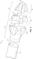
FIG. 2 is an exploded side view of a portion of the tool bit ofFIG. 1 . -
FIG. 3 is a flowchart illustrating a method of manufacturing the tool bit ofFIG. 1 . -
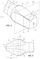
FIG. 4 is a perspective view of a portion of a tool bit according to another embodiment of the disclosure. -
FIG. 5 is a side view of a portion of the tool bit ofFIG. 1 illustrating a weld zone of the tool bit. - Before any embodiments of the disclosure are explained in detail, it is to be understood that the disclosure is not limited in its application to the details of construction and the arrangement of components set forth in the following description or illustrated in the following drawings. The disclosure is capable of supporting other embodiments and being practiced or being carried out in various ways. Also, it is to be understood that the phraseology and terminology used herein is for the purpose of description and should not be regarded as limiting. Terms of degree, such as "substantially," "about," "approximately," etc. are understood by those of ordinary skill to refer to reasonable ranges outside of the given value, for example, general tolerances associated with manufacturing, assembly, and use of the described embodiments.
-
FIGS. 1 and2 illustrate atool bit 10 for use with a tool (e.g., a power tool and/or a hand tool). The illustratedtool bit 10 includes a tool body having an insertion end portion 14 (e.g., a hexagonal drive portion), a workingend portion 18, and a connection portion 22 (e.g., a shank) extending between the workingend portion 18 and theinsertion end portion 14. - The
insertion end portion 14 is configured to be connected to the tool. More particularly, theinsertion end portion 14 is configured to be inserted into and received by a bit holder, chuck, or other structure coupled to or part of the tool. For ease of discussion, all of these types of structures will be referred to as bit holders herein. Theinsertion end portion 14 defines afirst end 26 of the tool body that is opposite the workingend portion 18. Theinsertion end portion 14 is composed of a first material. An outer surface on theinsertion end portion 14 is at least partially defined by anon-circular profile 30. In the illustrated embodiment, thenon-circular profile 30 is a hexagonal or hex-shaped profile configured to be received in a hexagonal or hex-shaped bit holder. In other embodiments, thenon-circular profile 30 may be other suitable profiles, such as D-shaped, flattened, oblong, triangular, square, octagonal, star-shaped, irregular, and the like. A portion of the outer surface on theinsertion end portion 14 not defined by thenon-circular profile 30 is defined by acircular profile 34. In other embodiments, thecircular profile 34 may be another profile, such as square, octagonal, star-shaped, irregular, and the like, or thecircular profile 34 may be omitted. Thecircular profile 34 is proximate theconnection portion 22. - The
connection portion 22 is positioned between the workingend portion 18 and the insertion end portion 14 (e.g., between the workingend portion 18 and the circular profile 34). Theconnection portion 22 includes a circular cross-sectional shape and defines a maximum radial dimension R3 (e.g., a maximum radius;FIG. 2 ) relative to a longitudinal axis of thetool bit 10. In additional embodiments, theconnection portion 22 may define a cross-sectional shape that is rectangular, octagonal, star-shaped, and the like. Theconnection portion 22 is also composed of the first material. - The working
end portion 18 is configured to engage with a fastener (e.g., a screw). More particularly, the workingend portion 18 is configured to drive the fastener into a workpiece. With reference toFIGS. 1 and2 , the workingend portion 18 includes a first segment 38 (e.g., a rearward segment) separated from a second segment 42 (e.g., a forward segment) by a connection interface 46. As shown inFIG. 2 , the connection interface 46 defines a maximum radial dimension R2 (e.g., a maximum radius) relative to the longitudinal axis of thetool bit 10. A cross-section of the workingend portion 18 at the maximum radius R2 defines a cross. As such, the maximum radius R2 is measured relative to a circle circumscribed by the cross. In additional embodiments, the cross-section may define a rectangle, an oval, a star, and the like. - With continued reference to
FIGS. 1 and2 , the illustratedforward segment 42 is composed of a second material and includes afirst portion 50 and asecond portion 54. Thesecond portion 54 includes a second end 58 (e.g., a tip) of the tool body that is opposite thefirst end 26. Thesecond portion 54 of the workingend portion 18 is the portion of thetool bit 10 that is inserted into a recess of the fastener when thetool bit 10 engages and drives the fastener. As such, thesecond portion 54 can be referenced as a fastener engagement portion. In particular, the workingend portion 18 is inserted into the fastener up to a depth measured from the second end 58 (e.g., the axial distance between thesecond end 58 and the interface between the first andsecond portions 50, 54). At this depth (e.g., a location at which fastener engagement ceases), an outer surface of the workingend portion 18 defines a maximum radial dimension R1 (e.g., a maximum radius;FIG. 2 ) relative to the longitudinal axis of thetool bit 10. In the depicted embodiment, a cross-section of the workingend portion 18 at the maximum radius R1 also defines a cross. As such, the maximum radius R1 is measured relative to a circle circumscribed by the cross. In additional embodiments, the cross-section may define a rectangle, an oval, a star, and the like. In the depicted embodiment, the radius R2 is larger than the radius R1. Additionally, the radius R1 and the radius R2 are both larger than the radius R3. Furthermore, a distance from thesecond end 58 to the location of the maximum radius R1 is less than a distance from thesecond end 58 to the location of the connection interface 46. - In the illustrated embodiment, the working
end portion 18 is composed of the first material and the second material. The second material defines the second segment 42 (e.g., the first andsecond portions 50, 54), and the first material defines a remainder of the working end portion 18 (e.g., the first segment 38) not defined by the second material. In the depicted embodiment, the second material has a hardness that is greater than a hardness of the first material. In other words, thesecond segment 42 is harder than thefirst segment 38. In some embodiments, the hardness of the second material is at least 5% greater than the hardness of the first material. In other embodiments, the hardness of the second material is between 5% and 30% greater than the hardness of the first material. - In the depicted embodiment, the first material is a tool steel. In some embodiments, the first material may be a low carbon steel, such as AISI 1018. AISI 1018 low carbon steel includes a balance of toughness, strength, and ductility. AISI 1018 low carbon steel includes approximately 0.14% to 0.2% carbon and 0.6% to 0.9% manganese. In other embodiments, the first material may be a high carbon steel, such as AISI 1065. AISI 1065 high carbon steel includes a high tensile strength. AISI high carbon steel includes approximately 0.6% to 0.7% carbon and 0.6% to 0.9% manganese. In additional embodiments, the first material may be an alternative material. The tool steel may have a hardness, for example between about 45 HRC and about 60 HRC. In some embodiments, the tool steel may have a hardness of between about 45 HRC and about 55 HRC.
- In the depicted embodiment, the second material is a high speed steel (HSS), such as PM M4. PM M4 high speed steel includes a fine grain size, small carbides, and a high steel cleanliness, which together provide high wear-resistance, high impact toughness, and high bend strength. PM M4 high speed steel includes approximately 1.4% carbon, 4% Chromium, 5.65% tungsten, 5.2% molybdenum, and 4% vanadium. In additional embodiments, the second material may be an alternative material (e.g., carbide). The high speed steel may have a hardness, for example, of 60 HRC or greater.
- By using the high or low carbon steel as the first material and the PM M4 high speed steel as the second material, the cost to manufacture the
tool bit 10 is minimized while the strength of thetool bit 10 is maintained. The cost to manufacture thetool bit 10 is minimized due to the material being used for the first material generally being inexpensive. The second material compensates for a lower strength of the first material. -
FIG. 3 illustrates amethod 62 of manufacturing thetool bit 10. Although the illustratedmethod 62 includes specific steps, not all of the steps need to be performed. In addition, the depicted steps do not need to be performed in the order presented. Themethod 62 may also include additional or alternative steps. - The illustrated
method 62 includes providing a first stock of material (step 66) composed of the first material and providing a second stock of material (step 70) composed of the second material.Step 74 includes fixing the first stock of material to the second stock of material (e.g., theforward segment 42 composed of the second material is secured to therearward segment 38 composed of the first material). Thesegments segments segments - An axial length of the second stock of material extending from the connection interface 46 is determined (step 78) as discussed in more detail below. The first stock of material and the second stock of material may then be machined or shaped (steps 82, 86) to form the
tool bit 10. Shaping the second stock of material (step 86) is based on the determined length (step 78) of the second stock of material. The first stock of material forms thefirst end 26 to the connection interface 46, and the second stock of material forms thesecond end 58 to the connection interface 46. In other words, the first stock of material is shaped to form theinsertion end portion 14, theconnection portion 22, and therearward portion 38. The second stock of material is shaped to form the workingend portion 18 from thesecond end 58 to the connection interface 46 (e.g., the forward segment 42). In other embodiments, themethod 62 can be different (e.g., the axial length of the second stock can be determined before the first and second stock of material are fixed together). - To determine a location of the connection interface 46 (step 78), the torsional stress τ R1 is calculated at the radius R1. The torsional stress τ R1 is related to an applied torque T R1, the radius R1 that the stress is occurring at, and a polar moment of inertia of the cross section J T
R1 at the radius R1. The torsional stress τ R1 at the radius R1 is expressed in Equation 1.
- The torsional stress τ R2 allowed at the radius R2 may then be calculated based on the torsional stress τ R1 at the radius R1. The torsional stress τ R2 allowed at the radius R2 is a percentage P of the torsional stress τ R1 at the radius R1. The percentage P is based on the difference in hardness between the first material and the second material. For example, if the first material was 80% the hardness of the second material, the torsional stress τ R2 allowed at the radius R2 would be 80% the torsional stress τ R1 at the radius R1. The torsional stress τ R2 allowed at the radius R2 is expressed in Equation 2.

- In addition to the torsional stress τ R2 allowed at the radius R2 being expressed in Equation 2, the torsional stress τ R2 allowed at the radius R2 may be related to the applied torque T R2, the radius R2, and a polar moment of inertia of the cross section J T
R2 at the radius R2. The torsional stress τ R2 allowed at the radius R2 is expressed in Equation 3.
- Equation 2 may be equated to Equation 3. Since the applied torque is the same through the drill bit, the torque T R1 at the radius R1 is the same as the torque T R2 at the radius R2. This expression is shown in Equation 4.

- The connection interface 46 may be selected such that the ratio of the radius R2 to the polar moment of the cross section J T
R2 at the radius R2 is less than or equal to the ratio of the radius R1 to the polar moment of the cross section J TR1 at the radius R1 multiplied by the percentage P difference between the hardnesses of the first material and the second material. - In some embodiments, the
tool bit 10 may have a reduced diameter portion (e.g., the illustrated connection portion 22) that allows thetool bit 10 to twist along its length. If thetool bit 10 includes this type of reduced diameter portion, the allowed torsional stress at the radius R2 is calculated to account for the reduced diameter portion. The radius R3 is located within the reduced diameter portion. The allowed torsional stress at the radius R2 is illustrated in Equation 5, which is similar to Equation 4.
- The connection interface 46 may be selected in view of both Equation 5 and Equation 4. In other words, the ratio of the radius R2 to the polar moment of the cross section J T
R2 at the radius R2 is additionally less than or equal to the ratio of the radius R3 to the polar moment of the cross section J TR3 at the radius R3 multiplied by the percentage P difference between the hardnesses of the first material and the second material. - An axial distance of the connection interface 46 from the
second end 58 may be determined (step 78) based on the ratio of the radius R2 to the polar moment of the cross section J TR2 at the radius R2. In other words, a radius and a polar moment may be calculated along a length of the workingend portion 18 to determine where the correct ratio occurs. For example, the axial distance of the connection interface 46 of a square tip tool bit 10 (e.g., size #2 square bit;FIG. 4 ) is based on the ratio of the radius R2 to the polar moment of the cross section J TR2 at the radius R2, as depicted in the table below. In this example, the hardness of the first material is 80% of the hardness of the second material, and the engagement distance (i.e., the location of the maximum radius R1) is about 0.08 inches from thesecond end 58. As such, the ratio of the radius R1 to the polar moment of the cross section J TR1 at the radius R1 is 2614.5. Using Equation 4 above, 80% of 2614.5 is 2091.6, which is the target ratio for R2. Based on the table below, the calculated ratio for radius R2 to the polar moment of the cross section J TR2 at the radius R2 is equal to or less than 2091.6 when the distance from thesecond end 58 is 0.16 inches. As such, the connection interface 46 between the first material and the second material for a size #2 square bit should be at about 0.16 inches from thesecond end 58.Distance from the second end (inches) Polar Moment of Inertia of the cross section Radius (inches) 
0.08 0.00003117 0.081496 2614.567 0.1 0.00003328 0.083071 2496.12 0.12 0.00003608 0.084646 2346.055 0.14 0.00004029 0.08622 2139.997 0.16 0.00004613 0.087795 1903.214 - Determining the axial distance of the connection interface 46 of the #2 square bit, as described above, can be applied to different sizes and/or types of
bits 10. The table below provides some examples of different sizes and types ofbits 10 and maintains that the hardness of the first material is 80% of the hardness of the second material. Specifically, the first column in the table below represents the type and size of the bit 10 (e.g., PH1 is a size #1 Phillips-head bit, PZ1 is a size #1 Pozidriv-head bit, SQ1 is a size #1 square-head bit, and T10 is asize # 10 Torx-head bit). In other words, the number associated with the type/geometry of the bit represents the standard size of the bit head. The table below shows, for example, the axial distance of the connection interface 46 of a size #1 Phillips-head bit relative to thetip 58 is about 0.087 inches. Specifically, a typical axial distance between thetip 58 and the radius R1 (e.g., a depth at which a #1 Phillips-head bit is received within a fastener) is about 0.075 inches. At that axial length, the polar moment of the cross section J TR1 at radius R1 is 0.00000840 and radius R1 is 0.058544 inches, such that a ratio of the radius R1 to the polar moment of the cross section J TR1 at the radius R1 is 6969.524. Taking in account for the differential between the hardnesses of the first and second materials, 80% of 6969.524 is about 5575.62, which is the target ratio for R2. As shown in the table below, the calculated ratio for radius R2 to the polar moment of the cross section J TR2 at the radius R2 is equal to or less than 5575.62 when the distance from thesecond end 58 is about 0.087 inches. As such, the connection interface 46 between the first material and the second material for a size #1 Phillips-head bit should be at about 0.087 inches from thesecond end 58. Similar calculations can be performed for the other types oftool bits 10 within the table below.Tip Type Distance between the radius R1 and the second end (inches) Distance between the connection interface and the second end (inches) Polar Moment of Inertia of the cross section Radius (inches) 
PH1 0.075 - 0.00000840 0.058544 6969.524 - 0.087 0.00001190 0.063900 5369.748 PH2 0.118 0.00004889 0.097677 1997.897 - 0.138 0.00007068 0.107480 1520.661 PH3 0.135 - 0.00011500 0.118110 1027.043 - 0.205 0.00014610 0.118110 808.419 PZ1 0.07 - 0.00000729 0.057489 7886.008 - 0.083 0.00000990 0.062500 6313.131 PZ2 0.13 - 0.00006320 0.104194 1648.639 - 0.16 0.00008610 0.113870 1322.532 PZ3 0.15 - 0.00012400 0.118110 952.500 - 0.25 0.00016247 0.118110 726.965 SQ1 0.08 - 0.00001498 0.066487 4438.385 - 0.13 0.00001984 0.069000 3477.823 SQ3 0.09 - 0.00005847 0.095134 1627.057 - 0.16 0.00007818 0.099180 1268.611 T10 0.07 - 0.00000702 0.053357 7600.712 - 0.12 0.00000922 0.055970 6070.499 T25 0.1 - 0.00004716 0.086691 1838.232 - 0.16 0.00006120 0.089000 1454.248 T30 0.12 - 0.00011100 0.108388 976.468 - 0.19 0.00014840 0.113250 763.140 T40 0.13 - 0.00024560 0.130452 531.156 - 0.212 0.00032340 0.136861 423.194 - In other types of
tool bits 10, a T15 bit includes a distance between the connection interface 46 and thetip 58 of about 0.12 inches with a fastener engagement depth of about 0.07 inches, a T25 bit includes a distance between the connection interface 46 and thetip 58 of about 0.16 inches with a fastener engagement depth of about 0.1 inches, and a T27 bit includes a distance between the connection interface 46 and thetip 58 of about 0.175 inches with a fastener engagement depth of about 0.11 inches. - With reference to
FIG. 5 , welding the first material to the second material may create aheat affect zone 90. The heat affectzone 90 has a lower material strength than a material strength of the second material. A distance at which theheat affect zone 90 has affected the second material is added to the axial distance of theoriginal connection interface 46a to offset a desiredconnection interface 46b an additional amount. For example, if theheat affect zone 90 is 0.11 inches and the initially calculated axial distance of theconnection interface 46a is 0.16 inches from thesecond end 58, a revisedconnection interface 46b to account for theheat affect zone 90 would be 0.27 inches from thesecond end 58. - In some scenarios, the
tool bit 10 may be stress relieved or heat treated after the first material is welded to the second material. In such scenarios, theheat affect zone 90 may be neglected, and an offset for the connection interface 46 would not need to be calculated. - Although the disclosure has been described in detail with reference to certain preferred embodiments, variations and modifications exist within the scope and spirit of one or more independent aspects of the disclosure as described. Various features and advantages of the disclosure are set forth in the following claims.
- Representative features are set out in the following clauses, which stand alone or may be combined, in any combination, with one or more features disclosed in the text and/or drawings of the specification.
- 1. A tool bit comprising:
- a drive portion configured to be selectively coupled to a tool, the drive portion being composed of a first material;
- a shank coupled to the drive portion, the shank being composed of the first material; and
- a working end portion including a first segment and a second segment, the first segment coupled to the shank and being composed of the first material, the second segment fixed to the first segment at a connection interface, the second segment being composed of a second material different than the first material, the second segment configured to engage a fastener for the working end portion to drive the fastener.
- 2. The tool bit of clause 1, wherein a distance between the connection interface and a tip of the second segment is based on a first ratio of a maximum radial dimension at a location along the tool bit to a polar moment at the location, and wherein the first ratio is multiplied by a percentage difference between hardnesses of the first material and the second material.
- 3. The tool bit of clause 2, wherein the distance between the connection interface and the tip is determined when a second ratio of a maximum radial dimension of the connection interface to a polar moment of the connection interface is less than or equal to the first ratio.
- 4. The tool bit of clause 3, wherein the location is included on the shank.
- 5. The tool bit of clause 3, wherein the location is included on the second segment, and wherein the second segment is configured to be received within the fastener to the location on the second segment in which the fastener ceases to engage the second segment.
- 6. The tool bit of clause 1, wherein the second material has a hardness greater than a hardness of the first material.
- 7. The tool bit of clause 6, wherein the second material is high speed steel.
- 8. The tool bit of clause 7, wherein the first material is tool steel.
- 9. The tool bit of clause 1, wherein the drive portion, the shank, and the first segment of the working end portion are formed from one piece of stock material.
- 10. The tool bit of clause 1, wherein the second segment is welded to the first segment at the connection interface.
- 11. A tool bit comprising:
- a drive portion configured to be selectively coupled to a tool, the drive portion being composed of a first material; and
- a working end portion including a shape configured to correspond with a recess of a fastener for the working end portion to engage and drive the fastener, the working end portion including a first segment and a second segment, the first segment located between the second segment and the drive portion, the first segment composed of the first material, the second segment fixed to the first segment at a connection interface, the second segment being composed of a second material different than the first material.
- 12. The tool bit of clause 11, wherein a distance between the connection interface and a tip of the second segment is based on a first ratio of a maximum radial dimension at a location along the tool bit to a polar moment at the location, and wherein the first ratio is multiplied by a percentage difference between hardnesses of the first material and the second material.
- 13. The tool bit of clause 12, wherein the distance between the connection interface and the tip is determined when a second ratio of a maximum radial dimension of the connection interface to a polar moment of the connection interface is less than or equal to the first ratio.
- 14. The tool bit of clause 13, further comprising a shank between the drive portion and the working end portion, wherein the location is included on the shank.
- 15. The tool bit of clause 13, wherein the location is included on the second segment, and wherein the second segment is configured to be received within the fastener to the location on the second segment in which the fastener ceases to engage the second segment.
- 16. The tool bit of clause 11, wherein the second material has a hardness greater than a hardness of the first material.
- 17. The tool bit of clause 16, wherein the second material is high speed steel.
- 18. The tool bit of clause 17, wherein the first material is tool steel.
- 19. The tool bit of clause 11, wherein the drive portion and the first segment of the working end portion are formed from one piece of stock material.
- 20. The tool bit of clause 11, wherein the second segment is welded to the first segment at the connection interface.
- 21. A method of manufacturing a tool bit, the method comprising:
- providing a first stock of material composed of a first material;
- providing a second stock of material composed of a second material different than the first material;
- fixing the first stock of material and the second stock of material together to form a connection interface;
- determining a length of the second stock of material extending from the connection interface;
- shaping the first stock of material to form a first segment of a working end portion; and
- shaping the second stock of material based on the determined length to form a second segment of the working end portion, the second segment configured to engage a fastener for the working end portion to drive the fastener.
- 22. The tool bit of clause 21, wherein determining the length of the second stock of material is based on a first ratio of a maximum radial dimension at a location along the first stock of material or the second stock of material to a polar moment at the location, and wherein the first ratio is multiplied by a percentage difference between hardnesses of the first material and the second material.
- 23. The tool bit of
clause 22, wherein the determined length is when a second ratio of a maximum radial dimension of the connection interface to a polar moment of the connection interface is less than or equal to the first ratio. - 24. The tool bit of clause 23, wherein shaping the first stock of material includes shaping a drive portion, a shank, and the first segment, wherein the drive portion is configured to be selectively coupled to a tool, wherein the shank is positioned between the drive portion and the first segment, and wherein the location is included on the shank.
- 25. The tool bit of clause 23, wherein the location is included on the second segment, and wherein the second segment is configured to be received within the fastener to the location on the second segment in which the fastener ceases to engage the second segment.
- 26. The method of clause 21, further comprising adjusting the determined length based on a heat affect zone created by fixing the first and second stock materials together.
- 27. The method of clause 21, wherein fixing the first stock of material and the second stock of material includes welding the first stock of material to the second stock of material.
Claims (11)
- A tool bit (10) comprising:a drive portion (14) configured to be selectively coupled to a tool, the drive portion (14) being composed of a first material;a shank (22) coupled to the drive portion (14), the shank (22) being composed of the first material; anda working end portion (18) including a first segment (38) and a second segment (42), the first segment (38) coupled to the shank (22) and being composed of the first material, the second segment (42) fixed to the first segment (38) at a connection interface (46), the second segment (42) being composed of a second material different than the first material,wherein a distance between the connection interface (46) and a tip (58) of the second segment is determined, andwherein the distance is adjusted based on a heat affect zone (90) created by fixing the first and second materials together.
- The tool bit of claim 1,wherein the connection interface 46 defines a maximum radial dimension (R2),wherein the distance of the connection interface (46) from the tip (58) of the second segment (42) is determined based on a ratio of the maximum radius (R2) to a polar moment of a cross section at the radius (R2).
- The tool bit of claim 1, wherein a distance at which the heat affect zone (90) has affected the second material is added to the distance of the connection interface (46a) to offset a desired connection interface (46b) an additional amount.
- The tool bit of claim 1, wherein the second segment is welded to the first segment at the connection interface.
- The tool bit of claim 1, wherein the second material has a hardness greater than a hardness of the first material.
- The tool bit of claim 5, wherein the second material is high speed steel.
- The tool bit of claim 6, wherein the first material is tool steel.
- The tool bit of claim 1, wherein the drive portion, the shank, and the first segment of the working end portion are formed from one piece of stock material.
- A method of manufacturing a tool bit (10), the method comprising:providing a first stock of material composed of a first material;providing a second stock of material composed of a second material different than the first material;fixing the first stock of material and the second stock of material together to form a connection interface (46);determining a length of the second stock of material extending from the connection interface (46);shaping the first stock of material to form a first segment (38) of a working end portion (18);shaping the second stock of material based on the determined length to form a second segment (42) of the working end portion (18), the second segment (42) configured to engage a fastener for the working end portion (18) to drive the fastener; andadjusting the determined length based on a heat affect zone (90) created by fixing the first and second stock materials together.
- The method of claim 9, wherein adjusting the determined length includes adding a distance at which the heat affect zone (90) has affected the second material to the determined length of the connection interface (46a) to offset a desired connection interface (46b) an additional amount.
- The method of claim 9, wherein fixing the first stock of material and the second stock of material includes welding the first stock of material to the second stock of material.
Applications Claiming Priority (3)
| Application Number | Priority Date | Filing Date | Title |
|---|---|---|---|
| US202062975787P | 2020-02-13 | 2020-02-13 | |
| EP21754434.5A EP4103358B1 (en) | 2020-02-13 | 2021-02-11 | Tool bit having a bimetal tip |
| PCT/US2021/017549 WO2021163251A1 (en) | 2020-02-13 | 2021-02-11 | Tool bit having a bimetal tip |
Related Parent Applications (1)
| Application Number | Title | Priority Date | Filing Date |
|---|---|---|---|
| EP21754434.5A Division EP4103358B1 (en) | 2020-02-13 | 2021-02-11 | Tool bit having a bimetal tip |
Publications (2)
| Publication Number | Publication Date |
|---|---|
| EP4467288A2 true EP4467288A2 (en) | 2024-11-27 |
| EP4467288A3 EP4467288A3 (en) | 2025-04-23 |
Family
ID=77291854
Family Applications (2)
| Application Number | Title | Priority Date | Filing Date |
|---|---|---|---|
| EP21754434.5A Active EP4103358B1 (en) | 2020-02-13 | 2021-02-11 | Tool bit having a bimetal tip |
| EP24205179.5A Pending EP4467288A3 (en) | 2020-02-13 | 2021-02-11 | Tool bit having a bimetal tip |
Family Applications Before (1)
| Application Number | Title | Priority Date | Filing Date |
|---|---|---|---|
| EP21754434.5A Active EP4103358B1 (en) | 2020-02-13 | 2021-02-11 | Tool bit having a bimetal tip |
Country Status (4)
| Country | Link |
|---|---|
| US (3) | US11673239B2 (en) |
| EP (2) | EP4103358B1 (en) |
| CN (1) | CN115066318B (en) |
| WO (1) | WO2021163251A1 (en) |
Families Citing this family (6)
| Publication number | Priority date | Publication date | Assignee | Title |
|---|---|---|---|---|
| CN115066318B (en) * | 2020-02-13 | 2024-05-28 | 米沃奇电动工具公司 | Tool bits with bimetallic tips |
| USD985349S1 (en) * | 2021-05-07 | 2023-05-09 | Hermann Frühm | Screwdriver bit |
| USD1039933S1 (en) * | 2021-12-20 | 2024-08-27 | William Norton | Driver |
| USD1118295S1 (en) * | 2023-03-10 | 2026-03-17 | Makita U.S.A., Inc. | Driver bit |
| USD1133823S1 (en) * | 2023-03-10 | 2026-07-14 | Makita, U.S.A., Inc. | Driver bit |
| CN118682691A (en) * | 2024-06-26 | 2024-09-24 | 美事满工具(海安)有限公司 | A composite metal material high-strength screwdriver bit and preparation method thereof |
Family Cites Families (43)
| Publication number | Priority date | Publication date | Assignee | Title |
|---|---|---|---|---|
| US4383784A (en) | 1980-01-07 | 1983-05-17 | Precision Twist Drill & Machine Co. | Method and means of manufacturing a rotary cutting tool |
| EP0100376A3 (en) | 1982-08-04 | 1984-08-29 | Rockwell International Corporation | Metal working tool |
| DE4243608C2 (en) | 1992-12-22 | 2000-10-19 | Werner Hermann Wera Werke | Tool |
| DE4303891A1 (en) * | 1993-02-10 | 1994-08-11 | Hahn Willi Gmbh | Screwdriver bit |
| DE19513366A1 (en) | 1995-04-08 | 1996-10-10 | Werner Hermann Wera Werke | Screwdriver, screwdriver bit or the like |
| DE19810192A1 (en) | 1998-03-10 | 1999-09-16 | Hilti Ag | Drilling tool |
| DE10190814D2 (en) | 2000-03-06 | 2003-03-27 | Holland Letz Felo Werkzeug | Screwdriver Bits |
| WO2002000396A1 (en) | 2000-06-27 | 2002-01-03 | Wera Werk Hermann Werner Gmbh & Co. Kg | Screw tool and production method thereof |
| US20050076749A1 (en) * | 2003-10-10 | 2005-04-14 | Liu Kuo Chen | Driving tool member having anti-slip device |
| DE10349415B4 (en) | 2003-10-21 | 2007-09-27 | Felo-Werkzeugfabrik Holland-Letz Gmbh | Method of making screwdriver bits |
| JP2005319523A (en) * | 2004-05-07 | 2005-11-17 | Kaneko Seisakusho:Kk | Tool with hard part |
| US20080166194A1 (en) | 2007-01-09 | 2008-07-10 | Durfee Laverne R | Drill bit |
| US20100003094A1 (en) | 2007-01-09 | 2010-01-07 | Irwin Industrial Tool Company | Drill bit |
| EP2018919A1 (en) | 2007-07-27 | 2009-01-28 | Joker Industrial Co., Ltd. | Screwing bit |
| DE102007041574A1 (en) | 2007-09-01 | 2009-03-05 | Wera-Werk Hermann Werner Gmbh & Co. Kg | Double-ended screwdriver bit, has hexagonal driving profiles joined by thinner intermediate section of reduced hardness |
| US9943934B2 (en) | 2008-10-08 | 2018-04-17 | Snap-On Incorporated | Method and tool product of differential heat treatment process |
| DE112009002723T5 (en) | 2008-11-07 | 2012-11-29 | Milwaukee Electric Tool Corp. | tool insert |
| DE102009003288A1 (en) | 2009-05-20 | 2010-11-25 | Hilti Aktiengesellschaft | drill |
| DE102009028020B4 (en) | 2009-07-27 | 2011-07-28 | Hilti Aktiengesellschaft | Drill and manufacturing process |
| USD711719S1 (en) | 2009-11-06 | 2014-08-26 | Milwaukee Electric Tool Corporation | Tool bit |
| DE102010028474A1 (en) | 2010-05-03 | 2011-11-03 | Hilti Aktiengesellschaft | Hollow drill and manufacturing process |
| CN201728404U (en) | 2010-05-29 | 2011-02-02 | 杭州东方型钢机械有限公司 | Hole saw extension rod |
| CN201728399U (en) | 2010-05-29 | 2011-02-02 | 杭州东方型钢机械有限公司 | Connecting rod for particle hole saw |
| DE102010038211A1 (en) | 2010-10-15 | 2012-04-19 | Wera-Werk Hermann Werner Gmbh & Co. Kg | Torque transmission device, in particular in the form of a chuck for bits |
| US9156094B2 (en) | 2012-01-23 | 2015-10-13 | Irwin Industrial Tool Company | Step drill for wood |
| CN102974871A (en) | 2012-11-27 | 2013-03-20 | 深圳市金洲精工科技股份有限公司 | Substrate for processing cutter and manufacturing method of substrate and drill bit using substrate |
| CN203030990U (en) | 2013-01-11 | 2013-07-03 | 郑州市钻石精密制造有限公司 | Reaming drill bit |
| USD734792S1 (en) | 2013-03-15 | 2015-07-21 | Black & Decker Inc. | Drill bit |
| US9333564B2 (en) | 2013-03-15 | 2016-05-10 | Black & Decker Inc. | Drill bit |
| USD737875S1 (en) | 2013-03-15 | 2015-09-01 | Black & Decker Inc. | Drill bit |
| US20140328640A1 (en) | 2013-03-15 | 2014-11-06 | Black & Decker Inc. | Bi-metal drill bit |
| EP2835201A1 (en) * | 2013-08-01 | 2015-02-11 | Black & Decker Inc. | Bi-metal drill bit |
| US10022845B2 (en) | 2014-01-16 | 2018-07-17 | Milwaukee Electric Tool Corporation | Tool bit |
| CN204209187U (en) | 2014-10-23 | 2015-03-18 | 汉中凯锐机电有限责任公司 | Bimetallic integral solder cutter |
| EP3117939A1 (en) | 2015-07-14 | 2017-01-18 | HILTI Aktiengesellschaft | Tool |
| TWI556915B (en) | 2016-04-07 | 2016-11-11 | 鴻安國際興業有限公司 | tool head |
| CN108015906A (en) | 2016-10-28 | 2018-05-11 | 圣戈班磨料磨具有限公司 | Hollow drill bit and its manufacture method |
| CN108118331A (en) * | 2016-11-30 | 2018-06-05 | 杭州巨星工具有限公司 | A kind of manufacturing method of screwdriver bit and screwdriver bit |
| CN206373406U (en) | 2016-12-13 | 2017-08-04 | 尖点科技股份有限公司 | Five-segment drill |
| DE102017107101A1 (en) | 2017-04-03 | 2018-10-04 | Jakob Lach Gmbh & Co. Kg | Method for producing a cutting tool for machining workpieces and cutting tool |
| CN106956049A (en) | 2017-04-28 | 2017-07-18 | 河北工业大学 | A kind of bimetallic critical point drilling tool and its application method |
| CN212351801U (en) * | 2017-12-01 | 2021-01-15 | 米沃奇电动工具公司 | Tool head for driving fasteners |
| CN115066318B (en) * | 2020-02-13 | 2024-05-28 | 米沃奇电动工具公司 | Tool bits with bimetallic tips |
-
2021
- 2021-02-11 CN CN202180013260.0A patent/CN115066318B/en active Active
- 2021-02-11 EP EP21754434.5A patent/EP4103358B1/en active Active
- 2021-02-11 EP EP24205179.5A patent/EP4467288A3/en active Pending
- 2021-02-11 US US17/798,284 patent/US11673239B2/en active Active
- 2021-02-11 WO PCT/US2021/017549 patent/WO2021163251A1/en not_active Ceased
-
2023
- 2023-05-01 US US18/141,746 patent/US12122019B2/en active Active
-
2024
- 2024-10-11 US US18/912,895 patent/US20250042002A1/en active Pending
Also Published As
| Publication number | Publication date |
|---|---|
| CN115066318A (en) | 2022-09-16 |
| US20230089769A1 (en) | 2023-03-23 |
| EP4103358B1 (en) | 2024-10-30 |
| CN115066318B (en) | 2024-05-28 |
| US11673239B2 (en) | 2023-06-13 |
| EP4467288A3 (en) | 2025-04-23 |
| US12122019B2 (en) | 2024-10-22 |
| EP4103358A4 (en) | 2024-03-20 |
| US20230264325A1 (en) | 2023-08-24 |
| EP4103358A1 (en) | 2022-12-21 |
| WO2021163251A1 (en) | 2021-08-19 |
| US20250042002A1 (en) | 2025-02-06 |
Similar Documents
| Publication | Publication Date | Title |
|---|---|---|
| EP4103358B1 (en) | Tool bit having a bimetal tip | |
| US11958168B2 (en) | Wear resistant tool bit | |
| US11691203B2 (en) | Step drill bit | |
| US20050135887A1 (en) | Twist drill | |
| US7789599B2 (en) | Drill | |
| US20080166194A1 (en) | Drill bit | |
| US20140023445A1 (en) | Power tool accessory | |
| CN103213179B (en) | For the step drill of wood | |
| US7367754B1 (en) | Variable helix rotary cutting tool | |
| US5971674A (en) | Deep hole drill bit | |
| EP4098387A1 (en) | Step drill bits | |
| JP2006055965A (en) | Cemented carbide drill causing low work hardening | |
| EP4338871A1 (en) | Drill | |
| KR20050085846A (en) | Deep hole drill eb90 | |
| EP1145934B1 (en) | Hollow rack shaft | |
| US20040223825A1 (en) | Broach tool and broaching method | |
| EP4067029B1 (en) | Spade drill bits | |
| US6708809B2 (en) | Clutch shaft stress relief | |
| JP4471894B2 (en) | Low work hardening carbide drill | |
| JP4526048B2 (en) | Threading tool | |
| CA2313749A1 (en) | Flexible shaft drill bit with removable cutting head | |
| JP4843317B2 (en) | Long drill with guide | |
| US20070237590A1 (en) | Rotary tool | |
| CN212239315U (en) | Hard bit twist drill | |
| US20230286065A1 (en) | Boring tool with multi-angled tip |
Legal Events
| Date | Code | Title | Description |
|---|---|---|---|
| PUAI | Public reference made under article 153(3) epc to a published international application that has entered the european phase |
Free format text: ORIGINAL CODE: 0009012 |
|
| STAA | Information on the status of an ep patent application or granted ep patent |
Free format text: STATUS: THE APPLICATION HAS BEEN PUBLISHED |
|
| AC | Divisional application: reference to earlier application |
Ref document number: 4103358 Country of ref document: EP Kind code of ref document: P |
|
| AK | Designated contracting states |
Kind code of ref document: A2 Designated state(s): AL AT BE BG CH CY CZ DE DK EE ES FI FR GB GR HR HU IE IS IT LI LT LU LV MC MK MT NL NO PL PT RO RS SE SI SK SM TR |
|
| PUAL | Search report despatched |
Free format text: ORIGINAL CODE: 0009013 |
|
| AK | Designated contracting states |
Kind code of ref document: A3 Designated state(s): AL AT BE BG CH CY CZ DE DK EE ES FI FR GB GR HR HU IE IS IT LI LT LU LV MC MK MT NL NO PL PT RO RS SE SI SK SM TR |
|
| RIC1 | Information provided on ipc code assigned before grant |
Ipc: B25B 15/00 20060101AFI20250318BHEP |
|
| STAA | Information on the status of an ep patent application or granted ep patent |
Free format text: STATUS: REQUEST FOR EXAMINATION WAS MADE |
|
| 17P | Request for examination filed |
Effective date: 20250509 |
|
| STAA | Information on the status of an ep patent application or granted ep patent |
Free format text: STATUS: EXAMINATION IS IN PROGRESS |
|
| 17Q | First examination report despatched |
Effective date: 20250923 |