EP4467281A1 - Repair methods for components having a damaged portion on a surface thereof - Google Patents
Repair methods for components having a damaged portion on a surface thereof Download PDFInfo
- Publication number
- EP4467281A1 EP4467281A1 EP24173803.8A EP24173803A EP4467281A1 EP 4467281 A1 EP4467281 A1 EP 4467281A1 EP 24173803 A EP24173803 A EP 24173803A EP 4467281 A1 EP4467281 A1 EP 4467281A1
- Authority
- EP
- European Patent Office
- Prior art keywords
- component
- feedstock mixture
- preform
- damaged portion
- thermal cycle
- Prior art date
- Legal status (The legal status is an assumption and is not a legal conclusion. Google has not performed a legal analysis and makes no representation as to the accuracy of the status listed.)
- Pending
Links
Images




Classifications
-
- B—PERFORMING OPERATIONS; TRANSPORTING
- B23—MACHINE TOOLS; METAL-WORKING NOT OTHERWISE PROVIDED FOR
- B23P—METAL-WORKING NOT OTHERWISE PROVIDED FOR; COMBINED OPERATIONS; UNIVERSAL MACHINE TOOLS
- B23P6/00—Restoring or reconditioning objects
- B23P6/002—Repairing turbine components, e.g. moving or stationary blades, rotors
- B23P6/005—Repairing turbine components, e.g. moving or stationary blades, rotors using only replacement pieces of a particular form
-
- B—PERFORMING OPERATIONS; TRANSPORTING
- B23—MACHINE TOOLS; METAL-WORKING NOT OTHERWISE PROVIDED FOR
- B23K—SOLDERING OR UNSOLDERING; WELDING; CLADDING OR PLATING BY SOLDERING OR WELDING; CUTTING BY APPLYING HEAT LOCALLY, e.g. FLAME CUTTING; WORKING BY LASER BEAM
- B23K35/00—Rods, electrodes, materials, or media, for use in soldering, welding, or cutting
- B23K35/02—Rods, electrodes, materials, or media, for use in soldering, welding, or cutting characterised by mechanical features, e.g. shape
- B23K35/0222—Rods, electrodes, materials, or media, for use in soldering, welding, or cutting characterised by mechanical features, e.g. shape for use in soldering or brazing
- B23K35/0244—Powders, particles or spheres; Preforms made therefrom
-
- B—PERFORMING OPERATIONS; TRANSPORTING
- B23—MACHINE TOOLS; METAL-WORKING NOT OTHERWISE PROVIDED FOR
- B23P—METAL-WORKING NOT OTHERWISE PROVIDED FOR; COMBINED OPERATIONS; UNIVERSAL MACHINE TOOLS
- B23P6/00—Restoring or reconditioning objects
- B23P6/002—Repairing turbine components, e.g. moving or stationary blades, rotors
-
- B—PERFORMING OPERATIONS; TRANSPORTING
- B23—MACHINE TOOLS; METAL-WORKING NOT OTHERWISE PROVIDED FOR
- B23P—METAL-WORKING NOT OTHERWISE PROVIDED FOR; COMBINED OPERATIONS; UNIVERSAL MACHINE TOOLS
- B23P6/00—Restoring or reconditioning objects
- B23P6/002—Repairing turbine components, e.g. moving or stationary blades, rotors
- B23P6/007—Repairing turbine components, e.g. moving or stationary blades, rotors using only additive methods, e.g. build-up welding
-
- B—PERFORMING OPERATIONS; TRANSPORTING
- B23—MACHINE TOOLS; METAL-WORKING NOT OTHERWISE PROVIDED FOR
- B23P—METAL-WORKING NOT OTHERWISE PROVIDED FOR; COMBINED OPERATIONS; UNIVERSAL MACHINE TOOLS
- B23P6/00—Restoring or reconditioning objects
- B23P6/04—Repairing fractures or cracked metal parts or products, e.g. castings
- B23P6/045—Repairing fractures or cracked metal parts or products, e.g. castings of turbine components, e.g. moving or stationary blades, rotors, etc.
-
- F—MECHANICAL ENGINEERING; LIGHTING; HEATING; WEAPONS; BLASTING
- F01—MACHINES OR ENGINES IN GENERAL; ENGINE PLANTS IN GENERAL; STEAM ENGINES
- F01D—NON-POSITIVE DISPLACEMENT MACHINES OR ENGINES, e.g. STEAM TURBINES
- F01D5/00—Blades; Blade-carrying members; Heating, heat-insulating, cooling or antivibration means on the blades or the members
- F01D5/005—Repairing methods or devices
-
- B—PERFORMING OPERATIONS; TRANSPORTING
- B23—MACHINE TOOLS; METAL-WORKING NOT OTHERWISE PROVIDED FOR
- B23K—SOLDERING OR UNSOLDERING; WELDING; CLADDING OR PLATING BY SOLDERING OR WELDING; CUTTING BY APPLYING HEAT LOCALLY, e.g. FLAME CUTTING; WORKING BY LASER BEAM
- B23K35/00—Rods, electrodes, materials, or media, for use in soldering, welding, or cutting
- B23K35/22—Rods, electrodes, materials, or media, for use in soldering, welding, or cutting characterised by the composition or nature of the material
- B23K35/24—Selection of soldering or welding materials proper
- B23K35/30—Selection of soldering or welding materials proper with the principal constituent melting at less than 1550°C
- B23K35/3033—Ni as the principal constituent
-
- F—MECHANICAL ENGINEERING; LIGHTING; HEATING; WEAPONS; BLASTING
- F05—INDEXING SCHEMES RELATING TO ENGINES OR PUMPS IN VARIOUS SUBCLASSES OF CLASSES F01-F04
- F05D—INDEXING SCHEME FOR ASPECTS RELATING TO NON-POSITIVE-DISPLACEMENT MACHINES OR ENGINES, GAS-TURBINES OR JET-PROPULSION PLANTS
- F05D2230/00—Manufacture
- F05D2230/80—Repairing, retrofitting or upgrading methods
Definitions
- the present disclosure relates generally to repair methods for components having a damaged portion on a surface thereof, and more particularly to repair method for high temperature components of gas turbine engines having a damaged portion on a surface thereof.
- High temperature components in gas turbine engines may be damaged, and need to be repaired to increase their life cycle.
- Conventional repair methods involve brazing techniques and brazing material that may not withstand the operating conditions of the component, not form a microstructural bond with the base material, and/or introduce undesirable phases such as silicides and borides in the base material.
- a repair method for a component having a damaged portion on a surface thereof including obtaining a feedstock mixture including base material particles and a binder, forming a preform with the feedstock mixture, placing the preform on the damaged portion of the surface of the component, and subjecting the component and the preform to at least one thermal cycle for forming a metallurgical bond in a solid state between the preform and the surface of the component after the at least one thermal cycle, the at least one thermal cycle occurring below a melting temperature of the component and the preform.
- the method may include any of the following features, in any combinations.
- the feedstock mixture consists of base material particles and binder.
- the feedstock mixture further includes particles of a melting point depressant material, and the feedstock mixture consists of the base material particles, the binder and the melting point depressant material.
- the feedstock mixture includes up to 3%-wt of the melting point depressant material.
- the component is made of a casting of a nickel-based superalloy, or of a casting of a cobalt-based superalloy.
- the base material particles are made of an alloy selected from the group consisting of Mar-M247, B1900Hf, IN792 and IN713.
- the obtaining of the feedstock mixture includes applying a vacuum, mixing and heating the feedstock mixture above a melting point of the binder.
- the repair method further includes at least one of thermal debinding and sintering of the preform prior to the placing of the preform on the damaged portion of the surface of the component.
- the forming of the preform includes injection molding of the feedstock mixture.
- the repair method further includes, prior to the placing of the preform on the damaged portion of surface of the component, at least one of stripping and cleaning the damaged portion of the surface of the component.
- the repair method further includes at least one of polishing the component to smooth the damaged portion of the surface of the component, and polishing the preform.
- the repair method further includes forming a recess in the surface of the component, and machining the preform to fit within the recess.
- the forming of the preform includes shaping the preform to a near net shape.
- the repair method further includes shaping the preform to a net shape.
- the repair method further includes applying a heat treatment cycle to the component and the preform after the formation of the metallurgical bond therebetween.
- a repair method for a component having a damaged portion on a surface thereof including obtaining a feedstock mixture including base material particles and a binder, heating and homogenizing the feedstock mixture to obtain a fluid feedstock mixture, pouring the fluid feedstock mixture on the damaged portion of the surface of the component, solidifying the fluid feedstock mixture to obtain a solidified feedstock mixture on the damaged portion of the surface of the component, and subjecting the component and the solidified feedstock mixture to at least one thermal cycle for forming a metallurgical bond in a solid state between the solidified feedstock mixture and the surface of the component after the at least one thermal cycle, the at least one thermal cycle occurring below a melting temperature of the component and the solidified feedstock mixture.
- the method may include any of the following features, in any combinations.
- the repair method further includes heating the component to a pre-determined temperature prior to the pouring of the fluid feedstock mixture on the damaged portion of the surface of the component.
- the repair method further includes debinding the solidified feedstock mixture prior to the subjecting to the at least one thermal cycle.
- the repair method further includes forming a preform by injecting the feedstock mixture into a mold, debinding and sintering the preform, placing the debound and sintered preform on the poured feedstock mixture prior to the solidification of the fluid feedstock mixture, and subjecting the component, the preform and the solidified feedstock mixture to the at least one thermal cycle.
- the feedstock mixture is a first feedstock mixture consisting of the base material particles, the binder and of a first ratio of melting point depressant material
- the repair method further includes obtaining a second feedstock mixture consisting of the base material particles, the binder and of a second ratio of melting point depressant material, the second ratio different from the first ratio, pouring the second feedstock mixture on the damaged portion of the surface of the component including the first solidified feedstock mixture, solidifying the second feedstock mixture to obtain a second solidified feedstock mixture on the damaged portion of the surface of the component, and subjecting the component and the first and second solidified feedstock mixtures to at least one thermal cycle for forming a metallurgical bond in a solid state between the first and second solidified feedstock mixtures and the surface of the component after the at least one thermal cycle.
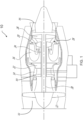
- FIG. 1 illustrates an example implementation of a gas turbine engine 10 of a type provided for use in subsonic flight, generally comprising in serial flow communication, a fan 12 through which ambient air is propelled, a compressor section 14 for pressurizing the air, a combustor 16 in which the compressed air is mixed with fuel and ignited for generating an annular stream of hot combustion gases, and a turbine section 18 for extracting energy from the combustion gases.
- High pressure rotor(s) 20 of the turbine section 18 are drivingly engaged to high pressure rotors 22 and 32 of the compressor section 14 through a high pressure shaft 24.
- Low pressure rotors 26 of the turbine section 18 are drivingly engaged to the fan rotor 12 and to low pressure rotors 30 of the compressor section 14 through a low pressure shaft 28 extending within the high pressure shaft 24 and rotating independently therefrom.
- gas turbine engine 10 may alternatively be another type of engine, for example a turboshaft engine, also generally comprising in serial flow communication a compressor section, a combustor, and a turbine section.
- a turboprop engine or turbojet may also apply.
- the engine 10 is described herein for flight applications, it should be understood that other uses, such as industrial or the like, may apply.
- the repair methods 100, 200, 300 about to be described are particularly suitable for components found in hot sections of the gas turbine engine 10, such as the turbine vane segments, vane rings, vane shrouds and other static components found in the turbine section 18.
- the term "hot gas path component” shall refer collectively to stationary vanes or blades and rotating blades of the turbine section 18, unless otherwise stated.
- the hot gas path components may be made of a casting of a superalloy material, such as a nickel-based superalloy or cobalt-based superalloy.
- Superalloy examples may include, but are not limited to, Rene 108, CM 247LC, Waspaloy, CMSX single crystal alloys, Mar-M246 TM , Mar-M247 TM , B1900Hf, IN 713, IN 738, and IN 939.
- Superalloys may provide a wide variety of physical properties, such as, but not limited to, high mechanical strength, high thermal creep deformation resistance, high corrosion or oxidation resistance, and good surface stability.
- superalloy materials do no lend themselves to conventional repair techniques such as welding. More particularly, with superalloy materials, conventional welding is insufficient because the weld does not result in a structure that has the same properties as the ones of the component. In addition, the welding may cause additional damages to the component, such as cracking.
- hot gas path components are subjected to high stress and high temperature conditions, and various types of damage or deterioration can occur. For example, wear tends to develop on the surface of hot gas path components as a result of rubbing contact between adjacent component(s). Cracks may appear as the result of high mechanical and thermal stresses due to high operating conditions. Degradation may occur as a result from oxidation or hot corrosion. Because the cost of components made of superalloys is relatively high, it is typically more desirable to repair these components than to replace them. For the same reason, new-make components that require repair due to manufacturing flaws are also preferably repaired instead of being scrapped.
- the repair methods 100, 200, 300 about to be described are intended to increase the service life of a component, such as a hot gas path component, and are contemplated to enable use of the component for at least one additional life cycle.
- a portion of a component 40 having a surface 42 including a damaged portion 44 can include a crack, a hole, fretting, corrosion defect, a buildup, etc. As such, different types of defects are contemplated.
- the component 40 is a hot gas path gas turbine engine component, such as a turbine blade, a vane or the like.
- the surface 42 can be an internal or external surface of the component 40.
- the repair methods 100, 300 involve the use of a preform 50 that is made of a feedstock mixture 52 including base material particles 54 and binder 56.
- the base material particles 54 have a composition similar to that of the component 40, and in some implementations a composition similar to that of the surface 42 of the component 40.
- the binder 56 includes a mixture of polymeric compounds that are wax-based or polyethylene glycol-based. The binder 56 enables the feedstock mixture 52 to flow during casting or injection molding. When the feedstock mixture 52 is used in injection molding, the binder 56 holds the base material particles 54 together in the desired shape in the form of the preform 50.
- the repair method 200 ( Fig. 5 ) does not involve the use of the preform 50 but rather involves pouring fluid feedstock mixture 52 on the damaged portion 44 of the surface 42 of the component 40, as depicted in Fig. 2D .
- the repair method 300 involves the use of fluid feedstock mixture 52 and a preform 50, as depicted in Fig. 2E .
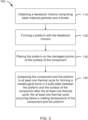
- the repair method 100 involves at step 110 obtaining a feedstock mixture 52 including the base material particles 54 and the binder 56.
- the repair method 100 includes forming a preform 50 with feedstock mixture 52.
- the preform 50 is placed on the damaged portion 44 of the surface 42 of the component 40.
- the method 100 includes subjecting the component 40 and the preform 50 to at least one thermal cycle for forming a metallurgical bond in a solid state between the preform 50 and the surface 42 of the component 40 after the at least one thermal cycle is complete, the at least one thermal cycle occurring below a melting temperature of the component 40 and the preform 50.
- the feedstock mixture 52 is obtained.
- the feedstock mixture 52 can include the base material particles 54 and the binder 56 as described above.
- the base material particles 54 is generally of a size below 60 ⁇ m, and in some implementations below 25 ⁇ m, to promote rapid sintering of the base material particles 54 and minimize porosity in the preform 50. Other particle sizes are contemplated.
- the feedstock mixture 52 consists of the base material particles 54 and the binder 56. Put differently, in some variants, the feedstock mixture 52 is free from an additional material that could have a melting point lower than that of the base material particles 54. In some implementations, the feedstock mixture 52 is free from a melting point depressant (MPD) material. In the repair methods 100, 200, 300, even if MPD is present in the feedstock mixture 52, there is no fusion involved during the repair process, which can limit or avoid the formation of borides, silicides and eutectic phases in the component 40, the preform 50 and/or at an interface therebetween.
- MPD melting point depressant
- the feedstock mixture 52 further includes a melting point depressant material 58.
- the feedstock mixture 52 consists of the base material particles 54, the binder 56 and the melting point depressant 58 particles.
- the melting point depressant 58 is an alloying material that decreases the melting temperature of an alloy.
- the melting point depressant 58 promotes sintering of the base material particles 54 and enables metallurgical continuity of the preform 50 with the component 40 at temperature below the melting point of the base material particles 54 and/or of the component 40.
- the melting point depressant 58 is a nickel-based alloy containing silicon and boron, such as BNi-2.
- melting point depressant 58 are contemplated, including and not limited to BNi-5, BNi-9, DF4B, Nicrobraz 150 or high melt/lowmelt mixtures.
- the feedstock mixture 52 has up to 3%-wt of the melting point depressant material 58. Having the melting point depressant 58 in the feedstock mixture 52 forming the preform 50 creates, under some conditions, a metallic cohesion between the preform 50 and the component 40, and with a melting temperature close to the base material particles 54.
- the ratio of melting point depressant material 58 is relatively low (for example up to 3%-wt)
- the feedstock mixture 52 During preparation of the feedstock mixture 52, vacuum and heat are applied at 112.
- the feedstock mixture 52 is heated above a melting point of the binder 56 and mixed to homogenize.
- the feedstock mixture 52 having the binder 56 liquefied and being is ready for forming the preform 50 is referred to as the fluid feedstock mixture 52.
- the temperature reached by the feedstock mixture 52, the fluid feedstock mixture 52 and the preform 50 is below the melting point of the base material particles 54.
- the repair methods 100, 200, 300 do not involve fusion of the base material particles 54 and/or of the material making the component 40.
- the preform 50 is formed with the fluid feedstock mixture 52 using injection molding techniques, in some implementations. More particularly, the preform 50 is formed with the fluid feedstock mixture 52 using metal injection molding techniques.
- the injection temperature is below 100°C and the injection pressure ranges between 20 to 50 PSI (about 1.36 atm, 138 kPa to about 3.40 atm, 345 kPa). Other injection temperatures and pressures are contemplated.
- the preform 50 can be of any suitable shape. For instance, the preform 50 can have a shape selected for improving contact with the surface 42 and/or to cover entirely the damaged portion 44.
- the preform 50 has no limitations as to the size, shape, or orientation of the damaged portion 44 to be filled and/or covered by the preform 50.
- the preform 50 can be shaped to a fit a pre-machined damage, to fill a V-out, to build up a flange or a surface, or to replace an edge of the component 40.
- the preform 50 is formed by injecting the fluid feedstock mixture 52 in a net shape mold (i.e. exactly the desired shape with all the details) or in a near net shape mold (i.e. roughly the desired shape without the details).
- the preform 50 can be shaped at 122a as a near net shape preform, or a net shape preform at 122b.
- the preform 50 is machined to the desired net shape at step 122c.
- the step 122c is referred to herein as "green machining" of the preform 50 as the preform 50 is still considered as a green part at this stage, i.e. where the preform 50 is made of solidified binder 56 and base material particles 54.
- the preform 50 being a green part is depicted in Fig. 2A .
- the preform 50 is then subjected to thermal debinding at step 124. More particularly, the preform 50 is heated to a temperature sufficient to thermally decompose a majority of the binder 56 present in the preform 50. In a variant, the preform 50 is placed in a crucible, surrounded with alumina powder, the alumina powder is compacted with pressure and vibration, and then the crucible containing the alumina powder and the preform 50 is heated for binder removal. After the debinding step 124, the preform 50 is considered a brown part, i.e. a non-densified polymer-free powder metallurgy part, and is depicted in Fig. 2B .
- the preform 50 is then subjected to sintering at step 126.
- the sintering step 126 involves heating the preform 50 to a sintering temperature that is below the melting point of the base material particles 54, which results in metallurgical bonding of the base material particles 54 through cohesion and densification.
- the preform 50 is then considered a sintered part and is depicted in Fig. 2C .
- the repair method 100 further includes post-sintering steps 126a, such as hot isostatic pressing and/or heat treatment for decreasing porosity and obtaining desired mechanical properties, for example.
- the repair method 100 further includes surface preparation steps 128 in some implementations.
- the surface preparation steps 128 about to be described may be performed alone or in combination, depending on the repair needed.
- Surface preparation steps 128 may include stripping of the component 40 at step 128a.
- the stripping 128a involves removing a surface portion of the surface 42 of the component to expose a subsurface of the component 40.
- the surface preparation steps 128 may also include cleaning the surface 42 of the component 40 at step 128b.
- the cleaning step 128b may include fluoride ions cleaning techniques where hydrogen fluoride (HF) gas attack deeply embedded oxides found on the surface 42 and/or in the damaged portion 44 to remove oxides therefrom. Other suitable cleaning techniques are contemplated.
- HF hydrogen fluoride
- a recess is formed in the surface 42 of the component 40, and the preform 50 is initially formed in an oversize condition relative to the recess to allow for machining the preform 50 to a size and shape that closely fits within and/or completely fills the recess.
- the size and shape of the preform 50 is selected to achieve a proper joint gap that will be filled after the thermal cycle of step 140.
- the condition of the preform 50 i.e. whether the preform 50 is a green part, a brown part or a sintered part, is also to be taken into account when machining the preform 50 to fit within the recess.
- the contact surface of the preform 50 i.e.
- the surface of the preform 50 intended to contact the surface 42 of the component 40 is polished to smooth the contact surface.
- the surface 42 of the component 40 including the damaged portion 44 is polished. The polishing steps 128d, 128e assist in improving the contact surface area between the preform 50 and the component 40.
- the preform 50 is placed on the damaged portion 44 of the surface 42 of the component 40 at step 130.
- the preform 50 is thus placed on the damaged portion 44 to cover entirely the damaged portion 44, or to be received within a recess formed in the surface 42, as described with reference to step 128c, depending on the situation.
- the preform 50 is compressed against the damaged portion 44 of the surface 42 to improve contact therebetween. The compression can be made manually, using small weights, using clamps or hydrostatic pressure applied to the preform 50 and the component 40, and for a pre-determined amount of time.
- the component 40 and the preform 50 are subjected to a thermal cycle for forming a metallurgical bond in a solid state between the preform 50 and the surface 42 of the component 40 after the thermal cycle.
- the thermal cycle occurs in or just below a sintering temperature range, which is below the melting point of the base material particles 54, and which results in metallurgical bonding of the base material particles 54, cohesion and densification.
- the metallurgical bonding means that there is metallurgical continuity between the material forming the component 40 and the material forming the preform 50.
- the sintering yields to a sintered preform 50 with good mechanical strength and low porosity.
- Suitable temperatures for the thermal cycle depends on the particular composition of the base material particles 54 and the melting point depressant 58 (if present), and the composition of the feedstock mixture 52.
- the preform 50 is thus bound to the component 40 in a solid state by sintering, and not by brazing nor diffusion bonding. Put differently, there is no fusion of the base material particles 54, the component 40 or of the melting point depressant 58 (if present) occurring during the thermal cycle of step 140. In implementations where the preform 50 has not yet been debound when placed on the component 40 (i.e. the preform 50 is still a green part), different thermal cycles may occur.
- the step 124 of thermal debinding of the preform 50 is first performed and then the thermal cycle of step 140 causes sintering of the preform 50 and bonds the preform 50 to the component 40.
- the thermal cycle of step 140 causes sintering of the preform 50 and bonds the preform 50 to the component 40.
- the steps 124, 126 and/or 140 are performed within a non-oxidizing atmosphere (i.e. vacuum, inert gas or inert gas partial pressure).
- the component 40 and the bonded preform 50 are subjected to post-processing steps including, and not limited to, machining of the preform 50 to remove excess material, mechanical and/or chemical cleaning, hot isostatic pressing, heat treatment, coating, etc.
- the heat treatment(s) can cause, in some implementations, precipitate-hardening within the sintered preform 50 and the component 40.
- the repair method 200 involves steps similar to that of the repair method 100, and such steps will be referred to using similar reference numerals, but in the 200 series, unless stated otherwise.
- the feedstock mixture 52 is obtained.
- the feedstock mixture 52 consists of the base material particles 54 and the binder 56.
- the feedstock mixture 52 further includes the melting point depressant material 58, and may consists of the base material particles 54, the binder 56 and the melting point depressant material 58.
- the feedstock mixture 52 is heated under vacuum and mixed to homogenize, yielding to a fluid feedstock mixture 52 where the binder 56 is liquefied and where the base material particles 54 are still solid.
- one or more surface preparation steps occur at step 228.
- the component 40 may be subjected to stripping at 228a, cleaning at 228b, and polishing at 228e.
- the component 40 is heated to a pre-determined temperature.
- the heating of the component 40 may slow down the solidification of the fluid feedstock mixture 52 about to be poured on the damaged portion 44 of the surface 42 of the component 40.
- the fluid feedstock mixture 52 is poured on the damaged portion 44 of the surface 42 of the component 40, sinks in the damaged portion 44 and wets the damaged portion 44 of the surface 42. Solidification of the fluid feedstock mixture 52 occurs on the damaged portion 44 of the surface 42 at step 232. At 234, the component 40 and the solidified feedstock mixture 52 are heated to thermally decompose the binder 56.
- the component 40 and the solidified feedstock mixture 52 are subjected to a thermal cycle for forming a metallurgical bond in a solid state between the solidified feedstock mixture 52 and the surface 42 of the component 40 after the thermal cycle.
- the thermal cycle occurs in a sintering temperature range, which is below the melting point of the base material particles 54, and which results in metallurgical bonding of the base material particles 54, cohesion and densification.
- the component 40 and the bonded feedstock mixture 52 are subjected to post-processing steps including, and not limited to, machining to remove excess material, mechanical and/or chemical cleaning, hot isostatic pressing, heat treatment, coating, etc.
- the heat treatment(s) can cause, in some implementations, precipitate-hardening within the feedstock mixture 52 and the component 40.
- the repair method 300 involves steps similar to that of the repair methods 100, 200 and such steps will be referred to using the same reference numerals, unless stated otherwise.
- the repair method 300 is a hybrid of the repair methods 100, 200 in that the repair method 300 involves forming a sintered preform 50 from fluid feedstock mixture 52 as described in steps 120, 126, pouring fluid feedstock mixture 52 on the damaged portion 44 of the surface 42 of the component 40 as described in step 230, then on to step 302 of placing the sintered preform 50 on the feedstock mixture 52 (as depicted in Fig. 2E ), and step 304 of subjecting the component 40, the preform 50 and the feedstock mixture 52 to the thermal cycles similar to steps 126, 140, 240.
- the repair method 300 includes forming the preform 50 as described in step 120.
- the preform 50 is heated for debinding and sintering as described with reference to steps 124, 126 prior to being placed on the feedstock mixture 52 at step 302.
- the preform 50 can also be formed in a near net shape or a net shape, as described with reference to steps 122a, 122b, 122c ( Fig. 4 ).
- the repair method 300 also includes the step 212 of heating and homogenizing the fluid feedstock mixture 52 that will be poured on the damaged portion 44, the step 229 of heating the component 40 to a pre-determined temperature.
- the repair method 300 can also include the surface preparation steps 128 described with reference to the repair method 100.
- the repair method 300 includes the step 302 of placing the preform 50 on the feedstock mixture 52, as depicted in Fig. 2E .
- the repair method 300 can also include the compressing of the preform 50 as described with reference to step 132 to ensure good contact between the preform 50, the feedstock mixture 52 and the component 40. Once the feedstock mixture 52 has solidified at step 232, debinding occurs at step 234.
- the component 40, the preform 50 and the debound feedstock mixture 52 are subjected to a thermal cycle similar to that described with reference to steps 140, 240, with the necessary adaptions due to the presence of both the feedstock mixture 52 and the preform 50.
- the repair method 300 may further include post-processing steps similar to that of step 150, such as machining and heat treating for precipitation hardening.
- Figs. 7A-7H an illustrative scenario involving steps from the repair methods 200, 300 and additional steps are presented.
- the component 40 is first heated to a pre-determined temperature as in step 229.
- the fluid feedstock mixture 52 having a first ratio of MPD 58 is poured on the damaged portion 44 as in step 230.
- the feedstock mixture 52 is let still to wet the damaged portion 44.
- excess material from the feedstock mixture 52 is removed (for instance by scraping), and the component 40 is rapidly cooled down from the pre-determined temperature.
- Fig. 7A-7H an illustrative scenario involving steps from the repair methods 200, 300 and additional steps are presented.
- the component 40 is first heated to a pre-determined temperature as in step 229.
- the fluid feedstock mixture 52 having a first ratio of MPD 58 is poured on the damaged portion 44 as in step 230.
- the feedstock mixture 52 is let still to wet the damaged portion 44.
- excess material from the feedstock mixture 52 is removed (for instance by
- fluid feedstock mixture 52' having a second ratio of MPD 58 different from the first ratio is then poured on the solidified feedstock mixture 52 and the damaged portion 44 of the still cooled down component 40.
- the first ratio of MPD 58 in the feedstock mixture 52 is greater than the second ratio of MPD 58 in the feedstock mixture 52'.
- the component 40 is reheated to the pre-determined temperature, and the poured feedstock mixture 52' fills the gap 53 and the region(s) not covered by the solidified feedstock mixture 52. If needed, a debound and sintered preform 50 is placed on the poured feedstock mixture 52', as shown in Fig. 7G . Excess material from the feedstock mixture 52' is removed, as shown in Fig. 7H .
- the assembly of the component 40, the feedstock mixture 52, feedstock mixture 52' and the preform 50 (if present) is slowly cooled down, leading to a first region of the repaired area with solidified feedstock mixture 52, and a second region with solidified feedstock mixture 52'.
- the steps of debinding 234 and of subjecting 304 the assembly to at least one thermal cycle for forming a metallurgical bond in a solid state between the preform 50 (if present), the feedstock mixtures 52, 52' and the surface 42 of the component 40 are then performed. If needed, post-processing steps 150 are performed.
- Fig. 8A-8H another illustrative scenario involving the steps from the repair methods 200, 300 and additional steps are shown.
- the component 40 is first heated to a pre-determined temperature as in step 229.
- the fluid feedstock mixture 52 having a first ratio of MPD 58 is poured on the damaged portion 44 as in step 230.
- the feedstock mixture 52 is let still to wet the damaged portion 44.
- Fig. 8C excess material from the fluid feedstock mixture 52 is removed (for instance by scraping) and the component 40 is cooled down for solidifying the feedstock mixture 52.
- the assembly of the component 40 and the solidified feedstock mixture 52 is then debound as in step 234 and subjected to thermal cycle(s) as in step 240.
- the sintered feedstock mixture 52 has shrunk, leaving a gap 53 between the sintered feedstock mixture 52 and some region(s) of the damaged portion 44.
- the assembly of the component 40 and the sintered feedstock mixture 52 is heated to a pre-determined temperature.
- fluid feedstock mixture 52' having a second ratio of MPD 58 different from the first ratio is then poured on the sintered feedstock mixture 52 and the damaged portion 44.
- Fig. 8D fluid feedstock mixture 52' having a second ratio of MPD 58 different from the first ratio
- the poured feedstock mixture 52' fills the gap 53 and wets the region(s) not covered by the solidified feedstock mixture 52. If needed, a debound and sintered preform 50 is placed on the poured feedstock mixture 52', as shown in Fig. 8G .
- Fig. 8H excess material from the feedstock mixture 52' is removed and the assembly of the component 40, the feedstock mixture 52, feedstock mixture 52' and the preform 50 (if present) is slowly cooled down, leading to a first region of the repaired area with solidified feedstock mixture 52, and a second region with solidified feedstock mixture 52'.
- the steps of debinding 234 and of subjecting 304 the assembly to at least one thermal cycle for forming a metallurgical bond in a solid state between the preform 50 (if present), the feedstock mixtures 52, 52' and the surface 42 of the component 40 are then performed. If needed, post-processing steps 150 are performed.
- the assembly is debound and sintered at two different times.
Landscapes
- Engineering & Computer Science (AREA)
- Mechanical Engineering (AREA)
- General Engineering & Computer Science (AREA)
- Powder Metallurgy (AREA)
Abstract
A repair method for a component having a damaged portion on a surface thereof includes obtaining a feedstock mixture comprising base material particles and a binder, forming a preform with the feedstock mixture, placing the preform on the damaged portion of the surface of the component, and subjecting the component and the preform to at least one thermal cycle for forming a metallurgical bond in a solid state between the preform and the surface of the component after the at least one thermal cycle, the at least one thermal cycle occurring below a melting temperature of the component and the preform. A repair method involving pouring fluid feedstock mixture on a damaged portion of the surface of the component is also disclosed.
Description
- The present disclosure relates generally to repair methods for components having a damaged portion on a surface thereof, and more particularly to repair method for high temperature components of gas turbine engines having a damaged portion on a surface thereof.
- High temperature components in gas turbine engines may be damaged, and need to be repaired to increase their life cycle.
- Conventional repair methods involve brazing techniques and brazing material that may not withstand the operating conditions of the component, not form a microstructural bond with the base material, and/or introduce undesirable phases such as silicides and borides in the base material.
- Therefore, improvements are needed.
- In accordance with a first aspect, there is provided a repair method for a component having a damaged portion on a surface thereof, the method including obtaining a feedstock mixture including base material particles and a binder, forming a preform with the feedstock mixture, placing the preform on the damaged portion of the surface of the component, and subjecting the component and the preform to at least one thermal cycle for forming a metallurgical bond in a solid state between the preform and the surface of the component after the at least one thermal cycle, the at least one thermal cycle occurring below a melting temperature of the component and the preform.
- The method may include any of the following features, in any combinations.
- In some implementations, the feedstock mixture consists of base material particles and binder.
- In some implementations, the feedstock mixture further includes particles of a melting point depressant material, and the feedstock mixture consists of the base material particles, the binder and the melting point depressant material.
- In some implementations, the feedstock mixture includes up to 3%-wt of the melting point depressant material.
- In some implementations, the component is made of a casting of a nickel-based superalloy, or of a casting of a cobalt-based superalloy.
- In some implementations, the base material particles are made of an alloy selected from the group consisting of Mar-M247, B1900Hf, IN792 and IN713.
- In some implementations, the obtaining of the feedstock mixture includes applying a vacuum, mixing and heating the feedstock mixture above a melting point of the binder.
- In some implementations, the repair method further includes at least one of thermal debinding and sintering of the preform prior to the placing of the preform on the damaged portion of the surface of the component.
- In some implementations, the forming of the preform includes injection molding of the feedstock mixture.
- In some implementations, the repair method further includes, prior to the placing of the preform on the damaged portion of surface of the component, at least one of stripping and cleaning the damaged portion of the surface of the component.
- In some implementations, the repair method further includes at least one of polishing the component to smooth the damaged portion of the surface of the component, and polishing the preform.
- In some implementations, the repair method further includes forming a recess in the surface of the component, and machining the preform to fit within the recess.
- In some implementations, the forming of the preform includes shaping the preform to a near net shape.
- In some implementations, the repair method further includes shaping the preform to a net shape.
- In some implementations, the repair method further includes applying a heat treatment cycle to the component and the preform after the formation of the metallurgical bond therebetween.
- In accordance with another aspect, there is provided a repair method for a component having a damaged portion on a surface thereof, the method including obtaining a feedstock mixture including base material particles and a binder, heating and homogenizing the feedstock mixture to obtain a fluid feedstock mixture, pouring the fluid feedstock mixture on the damaged portion of the surface of the component, solidifying the fluid feedstock mixture to obtain a solidified feedstock mixture on the damaged portion of the surface of the component, and subjecting the component and the solidified feedstock mixture to at least one thermal cycle for forming a metallurgical bond in a solid state between the solidified feedstock mixture and the surface of the component after the at least one thermal cycle, the at least one thermal cycle occurring below a melting temperature of the component and the solidified feedstock mixture.
- The method may include any of the following features, in any combinations.
- In some implementations, the repair method further includes heating the component to a pre-determined temperature prior to the pouring of the fluid feedstock mixture on the damaged portion of the surface of the component.
- In some implementations, the repair method further includes debinding the solidified feedstock mixture prior to the subjecting to the at least one thermal cycle.
- In some implementations, the repair method further includes forming a preform by injecting the feedstock mixture into a mold, debinding and sintering the preform, placing the debound and sintered preform on the poured feedstock mixture prior to the solidification of the fluid feedstock mixture, and subjecting the component, the preform and the solidified feedstock mixture to the at least one thermal cycle.
- In some implementations, the feedstock mixture is a first feedstock mixture consisting of the base material particles, the binder and of a first ratio of melting point depressant material, and the repair method further includes obtaining a second feedstock mixture consisting of the base material particles, the binder and of a second ratio of melting point depressant material, the second ratio different from the first ratio, pouring the second feedstock mixture on the damaged portion of the surface of the component including the first solidified feedstock mixture, solidifying the second feedstock mixture to obtain a second solidified feedstock mixture on the damaged portion of the surface of the component, and subjecting the component and the first and second solidified feedstock mixtures to at least one thermal cycle for forming a metallurgical bond in a solid state between the first and second solidified feedstock mixtures and the surface of the component after the at least one thermal cycle.
- Reference is now made to the accompanying figures in which:
-
Fig. 1 is a schematic cross-sectional view of an example gas turbine engine; -
Fig. 2A is a perspective view of a portion of a component having a damaged portion on a surface thereof, with a preform as a green part covering the damaged portion; -
Fig. 2B is a perspective view of the portion of the component ofFig. 2A , with a preform as a brown part covering the damaged portion; -
Fig. 2C is a perspective view of the portion of the component ofFig. 2A , with a preform as a sintered part covering the damaged portion; -
Fig. 2D is a perspective view of the portion of the component ofFig. 2A , with fluid feedstock mixture poured on the damaged portion; -
Fig. 2E is a perspective view of the portion of the component ofFig. 2A , with solidified feedstock mixture and a sintered preform on the damaged portion; -
Figs. 3 to 6 are flowcharts illustrating example repair methods for a component having a damaged portion on a surface thereof; -
Figs. 7A-7H are schematic views of an illustrative scenario of the repair methods ofFigs. 3 to 6 ; and -
Figs. 8A-8H are schematic view of another illustrative scenario of repair methods ofFigs. 3 to 6 . - It will be noted that throughout the appended drawings, like features are identified by like reference numerals.
- There are described herein repair methods for components of a gas turbine engine.
Fig. 1 illustrates an example implementation of agas turbine engine 10 of a type provided for use in subsonic flight, generally comprising in serial flow communication, afan 12 through which ambient air is propelled, acompressor section 14 for pressurizing the air, acombustor 16 in which the compressed air is mixed with fuel and ignited for generating an annular stream of hot combustion gases, and aturbine section 18 for extracting energy from the combustion gases. High pressure rotor(s) 20 of theturbine section 18 are drivingly engaged tohigh pressure rotors compressor section 14 through ahigh pressure shaft 24.Low pressure rotors 26 of theturbine section 18 are drivingly engaged to thefan rotor 12 and tolow pressure rotors 30 of thecompressor section 14 through alow pressure shaft 28 extending within thehigh pressure shaft 24 and rotating independently therefrom. - Although illustrated as a turbofan engine, the
gas turbine engine 10 may alternatively be another type of engine, for example a turboshaft engine, also generally comprising in serial flow communication a compressor section, a combustor, and a turbine section. A turboprop engine or turbojet may also apply. In addition, although theengine 10 is described herein for flight applications, it should be understood that other uses, such as industrial or the like, may apply. - The
repair methods gas turbine engine 10, such as the turbine vane segments, vane rings, vane shrouds and other static components found in theturbine section 18. As used herein, the term "hot gas path component" shall refer collectively to stationary vanes or blades and rotating blades of theturbine section 18, unless otherwise stated. The hot gas path components may be made of a casting of a superalloy material, such as a nickel-based superalloy or cobalt-based superalloy. Superalloy examples may include, but are not limited to, Rene 108, CM 247LC, Waspaloy, CMSX single crystal alloys, Mar-M246™, Mar-M247™, B1900Hf, IN 713, IN 738, and IN 939. Superalloys may provide a wide variety of physical properties, such as, but not limited to, high mechanical strength, high thermal creep deformation resistance, high corrosion or oxidation resistance, and good surface stability. However, superalloy materials do no lend themselves to conventional repair techniques such as welding. More particularly, with superalloy materials, conventional welding is insufficient because the weld does not result in a structure that has the same properties as the ones of the component. In addition, the welding may cause additional damages to the component, such as cracking. - During operation of the
gas turbine engine 10, hot gas path components are subjected to high stress and high temperature conditions, and various types of damage or deterioration can occur. For example, wear tends to develop on the surface of hot gas path components as a result of rubbing contact between adjacent component(s). Cracks may appear as the result of high mechanical and thermal stresses due to high operating conditions. Degradation may occur as a result from oxidation or hot corrosion. Because the cost of components made of superalloys is relatively high, it is typically more desirable to repair these components than to replace them. For the same reason, new-make components that require repair due to manufacturing flaws are also preferably repaired instead of being scrapped. Therepair methods - Before describing the
repair methods Figs. 2A to 2E , there is shown a portion of acomponent 40 having asurface 42 including a damagedportion 44. The damagedportion 44 can include a crack, a hole, fretting, corrosion defect, a buildup, etc. As such, different types of defects are contemplated. In some implementations, thecomponent 40 is a hot gas path gas turbine engine component, such as a turbine blade, a vane or the like. Thesurface 42 can be an internal or external surface of thecomponent 40. With additional reference toFigs. 3 ,4 and6 , therepair methods preform 50 that is made of afeedstock mixture 52 includingbase material particles 54 andbinder 56. Thebase material particles 54 have a composition similar to that of thecomponent 40, and in some implementations a composition similar to that of thesurface 42 of thecomponent 40. In some implementations, thebinder 56 includes a mixture of polymeric compounds that are wax-based or polyethylene glycol-based. Thebinder 56 enables thefeedstock mixture 52 to flow during casting or injection molding. When thefeedstock mixture 52 is used in injection molding, thebinder 56 holds thebase material particles 54 together in the desired shape in the form of thepreform 50. The repair method 200 (Fig. 5 ) does not involve the use of thepreform 50 but rather involves pouringfluid feedstock mixture 52 on the damagedportion 44 of thesurface 42 of thecomponent 40, as depicted inFig. 2D . Therepair method 300 involves the use offluid feedstock mixture 52 and apreform 50, as depicted inFig. 2E . - Referring now to
Fig. 3 , there is generally described therepair method 100 for thecomponent 40. Therepair method 100 involves atstep 110 obtaining afeedstock mixture 52 including thebase material particles 54 and thebinder 56. Atstep 120, therepair method 100 includes forming apreform 50 withfeedstock mixture 52. Atstep 130, thepreform 50 is placed on the damagedportion 44 of thesurface 42 of thecomponent 40. Atstep 140, themethod 100 includes subjecting thecomponent 40 and thepreform 50 to at least one thermal cycle for forming a metallurgical bond in a solid state between thepreform 50 and thesurface 42 of thecomponent 40 after the at least one thermal cycle is complete, the at least one thermal cycle occurring below a melting temperature of thecomponent 40 and thepreform 50. - Each one of the steps of the
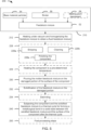
repair method 100 will now be described in more detail with reference toFig. 4 . Atstep 110, thefeedstock mixture 52 is obtained. Thefeedstock mixture 52 can include thebase material particles 54 and thebinder 56 as described above. Thebase material particles 54 is generally of a size below 60 µm, and in some implementations below 25 µm, to promote rapid sintering of thebase material particles 54 and minimize porosity in thepreform 50. Other particle sizes are contemplated. - In some implementations, the
feedstock mixture 52 consists of thebase material particles 54 and thebinder 56. Put differently, in some variants, thefeedstock mixture 52 is free from an additional material that could have a melting point lower than that of thebase material particles 54. In some implementations, thefeedstock mixture 52 is free from a melting point depressant (MPD) material. In therepair methods feedstock mixture 52, there is no fusion involved during the repair process, which can limit or avoid the formation of borides, silicides and eutectic phases in thecomponent 40, thepreform 50 and/or at an interface therebetween. - In some implementations, the
feedstock mixture 52 further includes a meltingpoint depressant material 58. In some implementations, thefeedstock mixture 52 consists of thebase material particles 54, thebinder 56 and themelting point depressant 58 particles. Themelting point depressant 58 is an alloying material that decreases the melting temperature of an alloy. In some implementations, themelting point depressant 58 promotes sintering of thebase material particles 54 and enables metallurgical continuity of thepreform 50 with thecomponent 40 at temperature below the melting point of thebase material particles 54 and/or of thecomponent 40. In an implementation, themelting point depressant 58 is a nickel-based alloy containing silicon and boron, such as BNi-2. Othermelting point depressant 58 are contemplated, including and not limited to BNi-5, BNi-9, DF4B,Nicrobraz 150 or high melt/lowmelt mixtures. In an implementation, thefeedstock mixture 52 has up to 3%-wt of the meltingpoint depressant material 58. Having themelting point depressant 58 in thefeedstock mixture 52 forming thepreform 50 creates, under some conditions, a metallic cohesion between thepreform 50 and thecomponent 40, and with a melting temperature close to thebase material particles 54. In addition, since the ratio of meltingpoint depressant material 58 is relatively low (for example up to 3%-wt), the amount of brittle microstructures due to the presence of borides and silicides in the repaired area, i.e. in thecomponent 40, thepreform 50 and/or at an interface therebetween, is very low. - During preparation of the
feedstock mixture 52, vacuum and heat are applied at 112. Thefeedstock mixture 52 is heated above a melting point of thebinder 56 and mixed to homogenize. Herein, thefeedstock mixture 52 having thebinder 56 liquefied and being is ready for forming thepreform 50 is referred to as thefluid feedstock mixture 52. It is noted that the temperature reached by thefeedstock mixture 52, thefluid feedstock mixture 52 and thepreform 50 is below the melting point of thebase material particles 54. Again, therepair methods base material particles 54 and/or of the material making thecomponent 40. - At
step 120, thepreform 50 is formed with thefluid feedstock mixture 52 using injection molding techniques, in some implementations. More particularly, thepreform 50 is formed with thefluid feedstock mixture 52 using metal injection molding techniques. In one implementation, the injection temperature is below 100°C and the injection pressure ranges between 20 to 50 PSI (about 1.36 atm, 138 kPa to about 3.40 atm, 345 kPa). Other injection temperatures and pressures are contemplated. Thepreform 50 can be of any suitable shape. For instance, thepreform 50 can have a shape selected for improving contact with thesurface 42 and/or to cover entirely the damagedportion 44. Thepreform 50 has no limitations as to the size, shape, or orientation of the damagedportion 44 to be filled and/or covered by thepreform 50. For instance, thepreform 50 can be shaped to a fit a pre-machined damage, to fill a V-out, to build up a flange or a surface, or to replace an edge of thecomponent 40. In a variant, thepreform 50 is formed by injecting thefluid feedstock mixture 52 in a net shape mold (i.e. exactly the desired shape with all the details) or in a near net shape mold (i.e. roughly the desired shape without the details). Hence, thepreform 50 can be shaped at 122a as a near net shape preform, or a net shape preform at 122b. In a variant where thepreform 50 is in a near net shape, thepreform 50 is machined to the desired net shape atstep 122c. Thestep 122c is referred to herein as "green machining" of thepreform 50 as thepreform 50 is still considered as a green part at this stage, i.e. where thepreform 50 is made of solidifiedbinder 56 andbase material particles 54. Thepreform 50 being a green part is depicted inFig. 2A . - In some implementations, the
preform 50 is then subjected to thermal debinding atstep 124. More particularly, thepreform 50 is heated to a temperature sufficient to thermally decompose a majority of thebinder 56 present in thepreform 50. In a variant, thepreform 50 is placed in a crucible, surrounded with alumina powder, the alumina powder is compacted with pressure and vibration, and then the crucible containing the alumina powder and thepreform 50 is heated for binder removal. After thedebinding step 124, thepreform 50 is considered a brown part, i.e. a non-densified polymer-free powder metallurgy part, and is depicted inFig. 2B . - In some implementations, the
preform 50 is then subjected to sintering atstep 126. Thesintering step 126 involves heating thepreform 50 to a sintering temperature that is below the melting point of thebase material particles 54, which results in metallurgical bonding of thebase material particles 54 through cohesion and densification. After thesintering step 126, thepreform 50 is then considered a sintered part and is depicted inFig. 2C . In some implementations, therepair method 100 further includespost-sintering steps 126a, such as hot isostatic pressing and/or heat treatment for decreasing porosity and obtaining desired mechanical properties, for example. - The
repair method 100 further includes surface preparation steps 128 in some implementations. The surface preparation steps 128 about to be described may be performed alone or in combination, depending on the repair needed. Surface preparation steps 128 may include stripping of thecomponent 40 atstep 128a. The stripping 128a involves removing a surface portion of thesurface 42 of the component to expose a subsurface of thecomponent 40. The surface preparation steps 128 may also include cleaning thesurface 42 of thecomponent 40 atstep 128b. The cleaningstep 128b may include fluoride ions cleaning techniques where hydrogen fluoride (HF) gas attack deeply embedded oxides found on thesurface 42 and/or in the damagedportion 44 to remove oxides therefrom. Other suitable cleaning techniques are contemplated. Atstep 128c, a recess is formed in thesurface 42 of thecomponent 40, and thepreform 50 is initially formed in an oversize condition relative to the recess to allow for machining thepreform 50 to a size and shape that closely fits within and/or completely fills the recess. The size and shape of thepreform 50 is selected to achieve a proper joint gap that will be filled after the thermal cycle ofstep 140. The condition of thepreform 50, i.e. whether thepreform 50 is a green part, a brown part or a sintered part, is also to be taken into account when machining thepreform 50 to fit within the recess. Atstep 128d the contact surface of the preform 50 (i.e. the surface of thepreform 50 intended to contact thesurface 42 of the component 40) is polished to smooth the contact surface. Atstep 128e, thesurface 42 of thecomponent 40 including the damagedportion 44 is polished. The polishing steps 128d, 128e assist in improving the contact surface area between thepreform 50 and thecomponent 40. - Still referring to
Fig. 4 , thepreform 50 is placed on the damagedportion 44 of thesurface 42 of thecomponent 40 atstep 130. Thepreform 50 is thus placed on the damagedportion 44 to cover entirely the damagedportion 44, or to be received within a recess formed in thesurface 42, as described with reference to step 128c, depending on the situation. In some implementations, atstep 132, thepreform 50 is compressed against the damagedportion 44 of thesurface 42 to improve contact therebetween. The compression can be made manually, using small weights, using clamps or hydrostatic pressure applied to thepreform 50 and thecomponent 40, and for a pre-determined amount of time. - At
step 140, thecomponent 40 and thepreform 50 are subjected to a thermal cycle for forming a metallurgical bond in a solid state between thepreform 50 and thesurface 42 of thecomponent 40 after the thermal cycle. The thermal cycle occurs in or just below a sintering temperature range, which is below the melting point of thebase material particles 54, and which results in metallurgical bonding of thebase material particles 54, cohesion and densification. The metallurgical bonding means that there is metallurgical continuity between the material forming thecomponent 40 and the material forming thepreform 50. The sintering yields to asintered preform 50 with good mechanical strength and low porosity. Suitable temperatures for the thermal cycle depends on the particular composition of thebase material particles 54 and the melting point depressant 58 (if present), and the composition of thefeedstock mixture 52. Thepreform 50 is thus bound to thecomponent 40 in a solid state by sintering, and not by brazing nor diffusion bonding. Put differently, there is no fusion of thebase material particles 54, thecomponent 40 or of the melting point depressant 58 (if present) occurring during the thermal cycle ofstep 140. In implementations where thepreform 50 has not yet been debound when placed on the component 40 (i.e. thepreform 50 is still a green part), different thermal cycles may occur. For example, thestep 124 of thermal debinding of thepreform 50 is first performed and then the thermal cycle ofstep 140 causes sintering of thepreform 50 and bonds thepreform 50 to thecomponent 40. In implementations where thepreform 50 is debound but has not yet been sintered when placed on the component 40 (i.e. thepreform 50 is still a brown part), other thermal cycle(s) may apply. For example, the thermal cycle ofstep 140 causes sintering of thepreform 50 and bonds thepreform 50 to thecomponent 40. In some implementations, thesteps - At
step 150, thecomponent 40 and the bondedpreform 50 are subjected to post-processing steps including, and not limited to, machining of thepreform 50 to remove excess material, mechanical and/or chemical cleaning, hot isostatic pressing, heat treatment, coating, etc. The heat treatment(s) can cause, in some implementations, precipitate-hardening within thesintered preform 50 and thecomponent 40. - Referring to
Fig. 5 , therepair method 200 will be described in detail. Therepair method 200 involves steps similar to that of therepair method 100, and such steps will be referred to using similar reference numerals, but in the 200 series, unless stated otherwise. - At
step 210, thefeedstock mixture 52 is obtained. As described above, in some implementations, thefeedstock mixture 52 consists of thebase material particles 54 and thebinder 56. In some implementations, thefeedstock mixture 52 further includes the meltingpoint depressant material 58, and may consists of thebase material particles 54, thebinder 56 and the meltingpoint depressant material 58. - At
step 212, thefeedstock mixture 52 is heated under vacuum and mixed to homogenize, yielding to afluid feedstock mixture 52 where thebinder 56 is liquefied and where thebase material particles 54 are still solid. - In some implementations, one or more surface preparation steps occur at
step 228. Thecomponent 40 may be subjected to stripping at 228a, cleaning at 228b, and polishing at 228e. - At
step 229, thecomponent 40 is heated to a pre-determined temperature. The heating of thecomponent 40 may slow down the solidification of thefluid feedstock mixture 52 about to be poured on the damagedportion 44 of thesurface 42 of thecomponent 40. - At
step 230, thefluid feedstock mixture 52 is poured on the damagedportion 44 of thesurface 42 of thecomponent 40, sinks in the damagedportion 44 and wets the damagedportion 44 of thesurface 42. Solidification of thefluid feedstock mixture 52 occurs on the damagedportion 44 of thesurface 42 atstep 232. At 234, thecomponent 40 and the solidifiedfeedstock mixture 52 are heated to thermally decompose thebinder 56. - At
step 240, thecomponent 40 and the solidifiedfeedstock mixture 52 are subjected to a thermal cycle for forming a metallurgical bond in a solid state between the solidifiedfeedstock mixture 52 and thesurface 42 of thecomponent 40 after the thermal cycle. As described above, the thermal cycle occurs in a sintering temperature range, which is below the melting point of thebase material particles 54, and which results in metallurgical bonding of thebase material particles 54, cohesion and densification. - At
step 250, thecomponent 40 and the bondedfeedstock mixture 52 are subjected to post-processing steps including, and not limited to, machining to remove excess material, mechanical and/or chemical cleaning, hot isostatic pressing, heat treatment, coating, etc. The heat treatment(s) can cause, in some implementations, precipitate-hardening within thefeedstock mixture 52 and thecomponent 40. - Referring now to
Fig. 6 , therepair method 300 will be described. Therepair method 300 involves steps similar to that of therepair methods repair method 300 is a hybrid of therepair methods repair method 300 involves forming asintered preform 50 fromfluid feedstock mixture 52 as described insteps fluid feedstock mixture 52 on the damagedportion 44 of thesurface 42 of thecomponent 40 as described instep 230, then on to step 302 of placing thesintered preform 50 on the feedstock mixture 52 (as depicted inFig. 2E ), and step 304 of subjecting thecomponent 40, thepreform 50 and thefeedstock mixture 52 to the thermal cycles similar tosteps - More particularly, the
repair method 300 includes forming thepreform 50 as described instep 120. Thepreform 50 is heated for debinding and sintering as described with reference tosteps feedstock mixture 52 atstep 302. Thepreform 50 can also be formed in a near net shape or a net shape, as described with reference tosteps Fig. 4 ). Therepair method 300 also includes thestep 212 of heating and homogenizing thefluid feedstock mixture 52 that will be poured on the damagedportion 44, thestep 229 of heating thecomponent 40 to a pre-determined temperature. Therepair method 300 can also include the surface preparation steps 128 described with reference to therepair method 100. Therepair method 300 includes thestep 302 of placing thepreform 50 on thefeedstock mixture 52, as depicted inFig. 2E . Therepair method 300 can also include the compressing of thepreform 50 as described with reference to step 132 to ensure good contact between thepreform 50, thefeedstock mixture 52 and thecomponent 40. Once thefeedstock mixture 52 has solidified atstep 232, debinding occurs atstep 234. Atstep 304, thecomponent 40, thepreform 50 and thedebound feedstock mixture 52 are subjected to a thermal cycle similar to that described with reference tosteps feedstock mixture 52 and thepreform 50. Therepair method 300 may further include post-processing steps similar to that ofstep 150, such as machining and heat treating for precipitation hardening. - Turning now to
Figs. 7A-7H , an illustrative scenario involving steps from therepair methods component 40 is first heated to a pre-determined temperature as instep 229. AtFig. 7A , thefluid feedstock mixture 52 having a first ratio ofMPD 58 is poured on the damagedportion 44 as instep 230. AtFig. 7B , thefeedstock mixture 52 is let still to wet the damagedportion 44. AtFig. 7C , excess material from thefeedstock mixture 52 is removed (for instance by scraping), and thecomponent 40 is rapidly cooled down from the pre-determined temperature. AtFig. 7D , after the rapid cool down, the solidifiedfeedstock mixture 52 shrinks and sticks on one side of the damagedportion 44, leaving agap 53 between the solidifiedfeedstock mixture 52 and some region(s) of the damagedportion 44. AtFig. 7E , fluid feedstock mixture 52' having a second ratio ofMPD 58 different from the first ratio is then poured on the solidifiedfeedstock mixture 52 and the damagedportion 44 of the still cooled downcomponent 40. In one implementation, the first ratio ofMPD 58 in thefeedstock mixture 52 is greater than the second ratio ofMPD 58 in the feedstock mixture 52'. Thecomponent 40 is reheated to the pre-determined temperature, and the poured feedstock mixture 52' fills thegap 53 and the region(s) not covered by the solidifiedfeedstock mixture 52. If needed, a debound and sinteredpreform 50 is placed on the poured feedstock mixture 52', as shown inFig. 7G . Excess material from the feedstock mixture 52' is removed, as shown inFig. 7H . The assembly of thecomponent 40, thefeedstock mixture 52, feedstock mixture 52' and the preform 50 (if present) is slowly cooled down, leading to a first region of the repaired area with solidifiedfeedstock mixture 52, and a second region with solidified feedstock mixture 52'. The steps ofdebinding 234 and of subjecting 304 the assembly to at least one thermal cycle for forming a metallurgical bond in a solid state between the preform 50 (if present), thefeedstock mixtures 52, 52' and thesurface 42 of thecomponent 40 are then performed. If needed,post-processing steps 150 are performed. - Turning now to
Fig. 8A-8H , another illustrative scenario involving the steps from therepair methods component 40 is first heated to a pre-determined temperature as instep 229. InFig. 8A , thefluid feedstock mixture 52 having a first ratio ofMPD 58 is poured on the damagedportion 44 as instep 230. InFig. 8B , thefeedstock mixture 52 is let still to wet the damagedportion 44. InFig. 8C , excess material from thefluid feedstock mixture 52 is removed (for instance by scraping) and thecomponent 40 is cooled down for solidifying thefeedstock mixture 52. The assembly of thecomponent 40 and the solidifiedfeedstock mixture 52 is then debound as instep 234 and subjected to thermal cycle(s) as instep 240. InFig. 8D , after the thermal cycle(s) ofstep 240, thesintered feedstock mixture 52 has shrunk, leaving agap 53 between thesintered feedstock mixture 52 and some region(s) of the damagedportion 44. The assembly of thecomponent 40 and thesintered feedstock mixture 52 is heated to a pre-determined temperature. AtFig. 8E , fluid feedstock mixture 52' having a second ratio ofMPD 58 different from the first ratio is then poured on thesintered feedstock mixture 52 and the damagedportion 44. InFig. 8F , the poured feedstock mixture 52' fills thegap 53 and wets the region(s) not covered by the solidifiedfeedstock mixture 52. If needed, a debound and sinteredpreform 50 is placed on the poured feedstock mixture 52', as shown inFig. 8G . AtFig. 8H , excess material from the feedstock mixture 52' is removed and the assembly of thecomponent 40, thefeedstock mixture 52, feedstock mixture 52' and the preform 50 (if present) is slowly cooled down, leading to a first region of the repaired area with solidifiedfeedstock mixture 52, and a second region with solidified feedstock mixture 52'. The steps ofdebinding 234 and of subjecting 304 the assembly to at least one thermal cycle for forming a metallurgical bond in a solid state between the preform 50 (if present), thefeedstock mixtures 52, 52' and thesurface 42 of thecomponent 40 are then performed. If needed,post-processing steps 150 are performed. Thus, in this illustrative scenario, the assembly is debound and sintered at two different times. - The implementations described in this document provide non-limiting examples of possible implementations of the present technology. Upon review of the present disclosure, a person of ordinary skill in the art will recognize that changes may be made to the implementations described herein without departing from the scope of the present technology.
Claims (15)
- A repair method for a component (40) having a damaged portion (44) on a surface (42) thereof, the method comprising:obtaining a feedstock mixture (52, 52') comprising base material particles (54) and a binder (56);forming a preform (50) with the feedstock mixture (52, 52');placing the preform (50) on the damaged portion (44) of the surface (42) of the component (40); andsubjecting the component (40) and the preform (50) to at least one thermal cycle for forming a metallurgical bond in a solid state between the preform (50) and the surface (42) of the component (40) after the at least one thermal cycle, the at least one thermal cycle occurring below a melting temperature of the component (40) and the preform (50).
- The method of claim 1, wherein the feedstock mixture (52, 52') consists of base material particles (54) and binder (56), and, optionally, wherein the feedstock mixture (52, 52') further comprises particles of a melting point depressant material (58), and the feedstock mixture (52, 52') consists of the base material particles (54), the binder (56) and the melting point depressant material (58), and, further optionally, wherein the feedstock mixture (52, 52') comprises up to 3%-wt of the melting point depressant material (58).
- The method of claim 1 or 2, wherein the component (40) is made of a casting of a nickel-based superalloy, or of a casting of a cobalt-based superalloy, and, optionally wherein the base material particles (54) are made of an alloy selected from the group consisting of Mar-M247™, B1900Hf, IN792 and IN713.
- The method of any preceding claim, wherein the obtaining of the feedstock mixture (52, 52') includes applying a vacuum, mixing and heating the feedstock mixture (52, 52') above a melting point of the binder (56).
- The method of any preceding claim, further comprising at least one of thermal debinding and sintering of the preform (50) prior to the placing of the preform (50) on the damaged portion (44) of the surface (42) of the component (40).
- The method of any preceding claim, wherein the forming of the preform (50) includes injection molding of the feedstock mixture (52, 52').
- The method of any preceding claim, further comprising, prior to the placing of the preform (50) on the damaged portion (44) of surface (42) of the component (40), at least one of stripping and cleaning the damaged portion (44) of the surface (42) of the component (40).
- The method of any preceding claim, further comprising at least one of polishing the component (40) to smooth the damaged portion (44) of the surface (42) of the component (40), and polishing the preform (50).
- The method of any preceding claim, further comprising forming a recess in the surface (42) of the component (40), and machining the preform (50) to fit within the recess.
- The method of any preceding claim, wherein the forming of the preform (50) comprises shaping the preform (50) to a near net shape, wherein, preferably the method further comprises shaping the preform (50) to a net shape.
- The method of any preceding claim, further comprising applying a heat treatment cycle to the component (40) and the preform (50) after the formation of the metallurgical bond therebetween.
- A repair method for a component (40) having a damaged portion (44) on a surface (42) thereof, the method comprising:obtaining a feedstock mixture (52, 52') comprising base material particles (54) and a binder (56);heating and homogenizing the feedstock mixture (52, 52') to obtain a fluid feedstock mixture (52, 52');pouring the fluid feedstock mixture (52, 52') on the damaged portion (44) of the surface (42) of the component (40);solidifying the fluid feedstock mixture (52, 52') to obtain a solidified feedstock mixture (52, 52') on the damaged portion (44) of the surface (42) of the component (40); andsubjecting the component (40) and the solidified feedstock mixture (52, 52') to at least one thermal cycle for forming a metallurgical bond in a solid state between the solidified feedstock mixture (52, 52') and the surface (42) of the component (40) after the at least one thermal cycle, the at least one thermal cycle occurring below a melting temperature of the component (40) and the solidified feedstock mixture (52, 52').
- The method of claim 12, further comprising heating the component (40) to a pre-determined temperature prior to the pouring of the fluid feedstock mixture (52, 52') on the damaged portion (44) of the surface (42) of the component (40), and, optionally, further comprising debinding the solidified feedstock mixture (52, 52') prior to the subjecting to the at least one thermal cycle.
- The method of claim 12 or 12, further comprising:forming a preform (50) by injecting the feedstock mixture (52, 52') into a mold;debinding and sintering the preform (50);placing the debound and sintered preform (50) on the poured feedstock mixture (52, 52') prior to the solidification of the fluid feedstock mixture (52, 52'); andsubjecting the component (40), the preform (50) and the solidified feedstock mixture (52, 52') to the at least one thermal cycle.
- The method of any one of claims 12 to 14, wherein the feedstock mixture (52) is a first feedstock mixture (52) consisting of the base material particles (54), the binder (56) and of a first ratio of melting point depressant material (58), and the method further comprises:obtaining a second feedstock mixture (52') consisting of the base material particles (54), the binder (56) and of a second ratio of melting point depressant material (58), the second ratio different from the first ratio;pouring the second feedstock mixture (52') on the damaged portion (44) of the surface (42) of the component (40) including the first solidified feedstock mixture (52);solidifying the second feedstock mixture (52') to obtain a second solidified feedstock mixture (52') on the damaged portion (44) of the surface (42) of the component (40); andsubjecting the component (40) and the first and second solidified feedstock mixtures (52, 52') to at least one thermal cycle for forming a metallurgical bond in a solid state between the first and second solidified feedstock mixtures (52, 52') and the surface (42) of the component (40) after the at least one thermal cycle.
Applications Claiming Priority (1)
| Application Number | Priority Date | Filing Date | Title |
|---|---|---|---|
| US18/144,026 US12053848B1 (en) | 2023-05-05 | 2023-05-05 | Repair methods for components having a damaged portion on a surface thereof |
Publications (1)
| Publication Number | Publication Date |
|---|---|
| EP4467281A1 true EP4467281A1 (en) | 2024-11-27 |
Family
ID=90971822
Family Applications (1)
| Application Number | Title | Priority Date | Filing Date |
|---|---|---|---|
| EP24173803.8A Pending EP4467281A1 (en) | 2023-05-05 | 2024-05-02 | Repair methods for components having a damaged portion on a surface thereof |
Country Status (3)
| Country | Link |
|---|---|
| US (1) | US12053848B1 (en) |
| EP (1) | EP4467281A1 (en) |
| CA (1) | CA3235700A1 (en) |
Citations (4)
| Publication number | Priority date | Publication date | Assignee | Title |
|---|---|---|---|---|
| US5156321A (en) * | 1990-08-28 | 1992-10-20 | Liburdi Engineering Limited | Powder metallurgy repair technique |
| US20120125979A1 (en) * | 2009-08-06 | 2012-05-24 | Mtu Aero Engines Gmbh | Repair of turbine components and solder alloy therefor |
| US20120211548A1 (en) * | 2011-02-23 | 2012-08-23 | Rolls-Royce Plc | Method of repairing a component |
| FR2981590A1 (en) * | 2011-10-21 | 2013-04-26 | Snecma | Producing sintered preform and assembling preform on part e.g. blade of turbomachine, by forming preform by sintering metal powder, assembling preform on part, repairing used part, and forming new part constituted of substrate and preform |
Family Cites Families (16)
| Publication number | Priority date | Publication date | Assignee | Title |
|---|---|---|---|---|
| US4726101A (en) * | 1986-09-25 | 1988-02-23 | United Technologies Corporation | Turbine vane nozzle reclassification |
| US5040718A (en) | 1987-10-16 | 1991-08-20 | Avco Corporation | Method of repairing damages in superalloys |
| US5822852A (en) * | 1997-07-14 | 1998-10-20 | General Electric Company | Method for replacing blade tips of directionally solidified and single crystal turbine blades |
| FR2768357B1 (en) * | 1997-09-18 | 1999-11-05 | Snecma | METHOD OF ASSEMBLING OR RECHARGING BY BRAZING-DIFFUSING PARTS IN TITANIUM ALUMINIURE |
| FR2785559B1 (en) | 1998-11-10 | 2001-03-02 | Metals Process Systems | METHOD FOR THE MANUFACTURE BY METALLURGY OF POWDERS OF AUTOBRASANT SHAPED PARTS |
| US6837417B2 (en) | 2002-09-19 | 2005-01-04 | Siemens Westinghouse Power Corporation | Method of sealing a hollow cast member |
| US20070107216A1 (en) * | 2005-10-31 | 2007-05-17 | General Electric Company | Mim method for coating turbine shroud |
| US7653994B2 (en) | 2006-03-22 | 2010-02-02 | General Electric Company | Repair of HPT shrouds with sintered preforms |
| US8356409B2 (en) * | 2007-11-01 | 2013-01-22 | United Technologies Corporation | Repair method for gas turbine engine components |
| US8087565B2 (en) | 2008-09-08 | 2012-01-03 | General Electric Company | Process of filling openings in a component |
| KR20150131295A (en) | 2013-03-15 | 2015-11-24 | 지멘스 에너지, 인코포레이티드 | Presintered preform for repair of superalloy component |
| US10265792B2 (en) | 2015-12-11 | 2019-04-23 | General Electric Company | Sinter-bonded hybrid article, method for forming hybrid article, and method for closing aperture |
| DE102018204088A1 (en) | 2018-03-16 | 2019-09-19 | Friedrich-Alexander-Universität Erlangen-Nürnberg | Process for the thermal treatment of metal powder injection molded components, a metal injection molded component and an aircraft engine |
| US10392938B1 (en) | 2018-08-09 | 2019-08-27 | Siemens Energy, Inc. | Pre-sintered preform for repair of service run gas turbine components |
| US11559847B2 (en) | 2020-01-08 | 2023-01-24 | General Electric Company | Superalloy part and method of processing |
| US11692446B2 (en) | 2021-09-23 | 2023-07-04 | Rolls-Royce North American Technologies, Inc. | Airfoil with sintered powder components |
-
2023
- 2023-05-05 US US18/144,026 patent/US12053848B1/en active Active
-
2024
- 2024-04-18 CA CA3235700A patent/CA3235700A1/en active Pending
- 2024-05-02 EP EP24173803.8A patent/EP4467281A1/en active Pending
Patent Citations (4)
| Publication number | Priority date | Publication date | Assignee | Title |
|---|---|---|---|---|
| US5156321A (en) * | 1990-08-28 | 1992-10-20 | Liburdi Engineering Limited | Powder metallurgy repair technique |
| US20120125979A1 (en) * | 2009-08-06 | 2012-05-24 | Mtu Aero Engines Gmbh | Repair of turbine components and solder alloy therefor |
| US20120211548A1 (en) * | 2011-02-23 | 2012-08-23 | Rolls-Royce Plc | Method of repairing a component |
| FR2981590A1 (en) * | 2011-10-21 | 2013-04-26 | Snecma | Producing sintered preform and assembling preform on part e.g. blade of turbomachine, by forming preform by sintering metal powder, assembling preform on part, repairing used part, and forming new part constituted of substrate and preform |
Also Published As
| Publication number | Publication date |
|---|---|
| US12053848B1 (en) | 2024-08-06 |
| CA3235700A1 (en) | 2025-06-17 |
Similar Documents
| Publication | Publication Date | Title |
|---|---|---|
| JP7532496B2 (en) | System and method for repairing hot gas turbine blades | |
| CA2581908C (en) | Repair of hpt shrouds with sintered preforms | |
| US8356409B2 (en) | Repair method for gas turbine engine components | |
| US5806751A (en) | Method of repairing metallic alloy articles, such as gas turbine engine components | |
| US5156321A (en) | Powder metallurgy repair technique | |
| US9121282B2 (en) | Methods for the controlled reduction of turbine nozzle flow areas and turbine nozzle components having reduced flow areas | |
| EP2692464B1 (en) | Methods for manufacturing titanium aluminide components from articles formed by consolidation processes | |
| KR102550572B1 (en) | Replacing Sections of Turbine Airfoils with Metallic Brazed Presintered Preforms | |
| CA2679517C (en) | Method for manufacturing an abrasive coating on a gas turbine component | |
| US9700941B2 (en) | Method for repairing a component for use in a turbine engine | |
| EP1055480A2 (en) | Repair of a recess in an article surface | |
| EP3132873A1 (en) | Additive manufacturing method of a turbine component | |
| JP2003176727A (en) | Repair method of hot parts and repaired hot parts | |
| EP1808263B1 (en) | Chordwidth restoration of a trailing edge of a turbine airfoil by laser clad | |
| US12053848B1 (en) | Repair methods for components having a damaged portion on a surface thereof | |
| EP2113633A2 (en) | Method to weld repair blade outer air seals | |
| US20070107216A1 (en) | Mim method for coating turbine shroud | |
| CN115194284B (en) | Furnaceless brazing method | |
| KR20230125082A (en) | Presintered preforms with high temperature capability, especially as abrasive coatings for gas turbine blades | |
| CA3211457A1 (en) | Additively depositing braze material | |
| WO2018226219A1 (en) | Methods for structural repair of industrial machine components |
Legal Events
| Date | Code | Title | Description |
|---|---|---|---|
| PUAI | Public reference made under article 153(3) epc to a published international application that has entered the european phase |
Free format text: ORIGINAL CODE: 0009012 |
|
| STAA | Information on the status of an ep patent application or granted ep patent |
Free format text: STATUS: THE APPLICATION HAS BEEN PUBLISHED |
|
| AK | Designated contracting states |
Kind code of ref document: A1 Designated state(s): AL AT BE BG CH CY CZ DE DK EE ES FI FR GB GR HR HU IE IS IT LI LT LU LV MC ME MK MT NL NO PL PT RO RS SE SI SK SM TR |
|
| STAA | Information on the status of an ep patent application or granted ep patent |
Free format text: STATUS: REQUEST FOR EXAMINATION WAS MADE |
|
| 17P | Request for examination filed |
Effective date: 20250527 |