EP1055480A2 - Repair of a recess in an article surface - Google Patents
Repair of a recess in an article surface Download PDFInfo
- Publication number
- EP1055480A2 EP1055480A2 EP00304468A EP00304468A EP1055480A2 EP 1055480 A2 EP1055480 A2 EP 1055480A2 EP 00304468 A EP00304468 A EP 00304468A EP 00304468 A EP00304468 A EP 00304468A EP 1055480 A2 EP1055480 A2 EP 1055480A2
- Authority
- EP
- European Patent Office
- Prior art keywords
- powder
- recess
- opening
- article
- wall
- Prior art date
- Legal status (The legal status is an assumption and is not a legal conclusion. Google has not performed a legal analysis and makes no representation as to the accuracy of the status listed.)
- Withdrawn
Links
Images


Classifications
-
- B—PERFORMING OPERATIONS; TRANSPORTING
- B23—MACHINE TOOLS; METAL-WORKING NOT OTHERWISE PROVIDED FOR
- B23P—METAL-WORKING NOT OTHERWISE PROVIDED FOR; COMBINED OPERATIONS; UNIVERSAL MACHINE TOOLS
- B23P6/00—Restoring or reconditioning objects
- B23P6/002—Repairing turbine components, e.g. moving or stationary blades, rotors
- B23P6/005—Repairing turbine components, e.g. moving or stationary blades, rotors using only replacement pieces of a particular form
-
- B—PERFORMING OPERATIONS; TRANSPORTING
- B23—MACHINE TOOLS; METAL-WORKING NOT OTHERWISE PROVIDED FOR
- B23K—SOLDERING OR UNSOLDERING; WELDING; CLADDING OR PLATING BY SOLDERING OR WELDING; CUTTING BY APPLYING HEAT LOCALLY, e.g. FLAME CUTTING; WORKING BY LASER BEAM
- B23K35/00—Rods, electrodes, materials, or media, for use in soldering, welding, or cutting
- B23K35/02—Rods, electrodes, materials, or media, for use in soldering, welding, or cutting characterised by mechanical features, e.g. shape
- B23K35/0222—Rods, electrodes, materials, or media, for use in soldering, welding, or cutting characterised by mechanical features, e.g. shape for use in soldering or brazing
- B23K35/0244—Powders, particles or spheres; Preforms made therefrom
-
- B—PERFORMING OPERATIONS; TRANSPORTING
- B23—MACHINE TOOLS; METAL-WORKING NOT OTHERWISE PROVIDED FOR
- B23K—SOLDERING OR UNSOLDERING; WELDING; CLADDING OR PLATING BY SOLDERING OR WELDING; CUTTING BY APPLYING HEAT LOCALLY, e.g. FLAME CUTTING; WORKING BY LASER BEAM
- B23K35/00—Rods, electrodes, materials, or media, for use in soldering, welding, or cutting
- B23K35/22—Rods, electrodes, materials, or media, for use in soldering, welding, or cutting characterised by the composition or nature of the material
- B23K35/24—Selection of soldering or welding materials proper
- B23K35/30—Selection of soldering or welding materials proper with the principal constituent melting at less than 1550°C
- B23K35/3033—Ni as the principal constituent
- B23K35/304—Ni as the principal constituent with Cr as the next major constituent
-
- B—PERFORMING OPERATIONS; TRANSPORTING
- B23—MACHINE TOOLS; METAL-WORKING NOT OTHERWISE PROVIDED FOR
- B23K—SOLDERING OR UNSOLDERING; WELDING; CLADDING OR PLATING BY SOLDERING OR WELDING; CUTTING BY APPLYING HEAT LOCALLY, e.g. FLAME CUTTING; WORKING BY LASER BEAM
- B23K35/00—Rods, electrodes, materials, or media, for use in soldering, welding, or cutting
- B23K35/22—Rods, electrodes, materials, or media, for use in soldering, welding, or cutting characterised by the composition or nature of the material
- B23K35/24—Selection of soldering or welding materials proper
- B23K35/30—Selection of soldering or welding materials proper with the principal constituent melting at less than 1550°C
- B23K35/3046—Co as the principal constituent
-
- B—PERFORMING OPERATIONS; TRANSPORTING
- B23—MACHINE TOOLS; METAL-WORKING NOT OTHERWISE PROVIDED FOR
- B23P—METAL-WORKING NOT OTHERWISE PROVIDED FOR; COMBINED OPERATIONS; UNIVERSAL MACHINE TOOLS
- B23P6/00—Restoring or reconditioning objects
- B23P6/002—Repairing turbine components, e.g. moving or stationary blades, rotors
- B23P6/007—Repairing turbine components, e.g. moving or stationary blades, rotors using only additive methods, e.g. build-up welding
-
- F—MECHANICAL ENGINEERING; LIGHTING; HEATING; WEAPONS; BLASTING
- F01—MACHINES OR ENGINES IN GENERAL; ENGINE PLANTS IN GENERAL; STEAM ENGINES
- F01D—NON-POSITIVE DISPLACEMENT MACHINES OR ENGINES, e.g. STEAM TURBINES
- F01D5/00—Blades; Blade-carrying members; Heating, heat-insulating, cooling or antivibration means on the blades or the members
- F01D5/005—Repairing methods or devices
-
- B—PERFORMING OPERATIONS; TRANSPORTING
- B23—MACHINE TOOLS; METAL-WORKING NOT OTHERWISE PROVIDED FOR
- B23K—SOLDERING OR UNSOLDERING; WELDING; CLADDING OR PLATING BY SOLDERING OR WELDING; CUTTING BY APPLYING HEAT LOCALLY, e.g. FLAME CUTTING; WORKING BY LASER BEAM
- B23K2101/00—Articles made by soldering, welding or cutting
- B23K2101/001—Turbines
-
- B—PERFORMING OPERATIONS; TRANSPORTING
- B23—MACHINE TOOLS; METAL-WORKING NOT OTHERWISE PROVIDED FOR
- B23K—SOLDERING OR UNSOLDERING; WELDING; CLADDING OR PLATING BY SOLDERING OR WELDING; CUTTING BY APPLYING HEAT LOCALLY, e.g. FLAME CUTTING; WORKING BY LASER BEAM
- B23K35/00—Rods, electrodes, materials, or media, for use in soldering, welding, or cutting
- B23K35/22—Rods, electrodes, materials, or media, for use in soldering, welding, or cutting characterised by the composition or nature of the material
- B23K35/24—Selection of soldering or welding materials proper
- B23K35/30—Selection of soldering or welding materials proper with the principal constituent melting at less than 1550°C
-
- F—MECHANICAL ENGINEERING; LIGHTING; HEATING; WEAPONS; BLASTING
- F05—INDEXING SCHEMES RELATING TO ENGINES OR PUMPS IN VARIOUS SUBCLASSES OF CLASSES F01-F04
- F05D—INDEXING SCHEME FOR ASPECTS RELATING TO NON-POSITIVE-DISPLACEMENT MACHINES OR ENGINES, GAS-TURBINES OR JET-PROPULSION PLANTS
- F05D2230/00—Manufacture
- F05D2230/80—Repairing, retrofitting or upgrading methods
-
- Y—GENERAL TAGGING OF NEW TECHNOLOGICAL DEVELOPMENTS; GENERAL TAGGING OF CROSS-SECTIONAL TECHNOLOGIES SPANNING OVER SEVERAL SECTIONS OF THE IPC; TECHNICAL SUBJECTS COVERED BY FORMER USPC CROSS-REFERENCE ART COLLECTIONS [XRACs] AND DIGESTS
- Y10—TECHNICAL SUBJECTS COVERED BY FORMER USPC
- Y10T—TECHNICAL SUBJECTS COVERED BY FORMER US CLASSIFICATION
- Y10T29/00—Metal working
- Y10T29/49—Method of mechanical manufacture
- Y10T29/49316—Impeller making
- Y10T29/49318—Repairing or disassembling
Definitions
- This invention relates to repair of a recess in an article surface. More particularly, it relates to repair of a recess generated during operation of a power generating apparatus, for example a gas turbine engine.
- Such conditions include a combination of oxidation and corrosion materials and gasses, erosive air borne particles, and mechanical actions resulting from rotation of the engine.
- one or more recesses are produced in a surface of components.
- Recesses include cracks, crevices, surface erosion, dents, indentations, separations, holes in or through the substrate, etc., commonly observed by those working in the repair of gas turbine engine components.
- the present invention in one form, provides a method for repairing a recess in an article surface, including providing first and second metallic powders with different melting temperatures, the second having a melting temperature lower than the first.
- the first powder is disposed in the recess substantially to fill the recess.
- the second powder is disposed over the first powder in an amount that at least will fill the recess up to the article surface after melting and flowing of the second powder into the recess.
- the powders then are heated to a treatment temperature at least at the melting temperature of the second powder and less than the melting temperature of the first powder for a time sufficient to melt the second powder, to flow the melted second powder about the first powder, and to bond the second powder to a surface of the recess.
- the material in the recess is cooled to provide a repair material in the recess.
- Figure 1 is a diagrammatic, fragmentary, sectional view of a recess in the form of a crack in an article surface.
- Figure 2 is a view as in Figure 1 in which a first metal powder is disposed in the crack.
- Figure 3 is a view as in Figure 2 in which pressure is applied to the first powder to assure filling of the crack.
- Figure 4 is the view of Figure 3 with a second metal powder disposed over the first powder.
- Figure 5 is the view of Figure 4 after heating to a treatment temperature to melt and enable flow of the second powder about the first powder.
- Figure 6 is the view of Figure 5 after removal of excess material from the article surface.
- Figure 7 is a diagrammatic, fragmentary, sectional view of an outer wall of an air cooled article showing an air cooling opening through the wall.
- Figure 8 is a view as in Figure 7 in which the air cooling opening is filled with a mixture including the first metallic powder and a binder, with excess mixture extending from an inner wall surface.
- Figure 9 is the view of Figure 8 showing excess mixture removed from the inner wall surface.
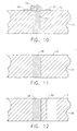
- Figure 10 is the view of Figure 9 with a second metallic powder disposed over the first powder.
- Figure 11 is the view as in Figure 10, comparable to the view of Figure 6, after heating to a treatment temperature to melt and enable flow of the second powder about the first powder followed by removal of excess material from the article surface at the repaired, filled opening.
- Figure 12 is the view of Figure 12 with a replacement air cooling opening generated through the article wall adjacent the repaired, filled opening.
- the present invention has been evaluated more particularly in connection with the repair of recesses, primarily cracks and/or erosion, in gas turbine vanes typical of hot operating gas turbine engine components.
- Such components on which the present invention can be used include turbine blades and vanes, shrouds, and turbine component support structures, made of high temperature superalloys based on Fe, Ni, Co or their combinations.
- it has been evaluated in connection with the repair, replacement and/or relocation of cooling openings through a wall of such components.
- the invention is of particular interest in the repair of the airfoil portion of turbine components because they experience the strenuous operating conditions found in that portion of the engine.
- the method of the present invention through the combination and order of defined metallic powders, provides within a recess flow or wicking of a lower melting metallic powder in and around a higher melting metallic powder having a melting temperature greater than a treatment temperature.
- the result is a substantially non-porous repair, filling a recess for integrity of the article being repaired.
- a recess is shown generally at 10 in the form of a crack in article surface 12 of metal article 14, for example a wall of a gas turbine engine airfoil.
- Recess 10 includes a recess surface 16 that defines an interior wall of the recess or crack.
- Repair of recess 10 in that embodiment included providing a first metallic powder 18 having a first melting temperature, and disposing the first powder in the recess, as shown in Figure 2.
- an external pressure or force represented by arrow 20 in Figure 3 was used in this evaluation.
- pressure was applied to the first powder using an ordinary cotton swab to press the powder into the recess. Any appropriate amount of pressure can be applied if deemed necessary to fill the recess with the first powder.
- a second metallic powder 22 was mixed with a liquid binder 24 of the type ordinarily used in metal brazing and that will decompose substantially without residue upon heating. This provides a second powder mixture. As shown in Figure 4, the second powder mixture of second metal powder 22 and binder 24 was applied over first powder 18. For convenience, an ordinary commercial brazing stop-off material 26 was applied by painting about recess 10 to avoid excess flow of second powder 22 onto article surface 12 during subsequent heating and melting of the second powder.
- repair material 28 is in another form including at least the diffusion product of the first and second powders.
- an outer wall 30 of an air cooled turbine airfoil included an air cooling opening or hole 32 through wall 30.
- An air cooled wall in a gas turbine engine member, such as a turbine blade airfoil is shown in U.S. Patent 5,458,461 - Lee et al. (patented October 17, 1995). Repair of such an opening can be required, for example, because of damage to the opening, by redesign of a cooling pattern specifying repositioning of the opening, or both.
- first metallic powder 18 was mixed with a liquid binder as described above in connection with binder 24 to provide a first powder mixture 34, as shown in Figure 8, to hold the first powder 18 within opening 32.
- application of pressure such as 20 in Figure 3 forced first powder mixture 34 from opening 32, as shown generally at 36 on inner surface 38 of wall 30 in Figure 8.
- Such excess first mixture was removed, such as by wiping with a cotton swab, to provide the condition shown in Figure 9.
- a second powder mixture 40, Figure 10, of second metallic powder 22 and binder 24 was applied over first mixture 34, as described in connection with Figure 4 above.
- the assembly was heated at the treatment temperature, cooled and excess material was removed as described in connection with Figures 5 and 6 to provide a repair material 28 bonded within opening 32 as shown in Figure 11.
- the region of repaired opening 32 in one example was regenerated by drilling, such as electrodischarge material removal or laser drilling commonly used in the gas turbine engine manufacturing art.
- the position of the air cooling opening was relocated by such drilling of a replacement opening 42 adjacent repaired opening 32.
- gas turbine engine turbine vane airfoils were observed to have cracks in the airfoil surfaces.
- the vane was made from a high temperature Co base superalloy commercially available as X-40 alloy, having a melting temperature greater than about 2300° F.
- the first metallic powder used in these examples was a powder of a high temperature Ni base superalloy sometimes referred to as Rene' N4 alloy, also having a melting temperature greater than about 2300° F.
- the second metallic powder used in these examples was a mixture of a plurality of distinct lower melting alloys of the general type described in the above-identified U.S. Patent 4,830,934 and sometimes referred to as SA 650 alloy.
- the binder used was a commercial liquid material called Nicrobraze cement, generally used in connection with brazing. When mixed into a powder mixture or slurry with the metallic powders, about 10 - 15 % by weight of the binder was used, the balance being the metallic powder.
- Foreign surface material first was removed from the airfoil surface about the cracks.
- the dry first powder was disposed and the pressed into the cracks, as shown in Figures 2 and 3, using a cotton swab to press the first powder into and fill the crack substantially to the airfoil surface.
- Other of the series of examples used a mixture of the first powder and the binder to provide a first powder mixture.
- a second powder mixture of the second powder and binder was disposed over the first powder as shown in Figure 4.
- a commercial brazing stop off material was applied with a brush to the airfoil surface about each crack outside of the second powder mixture.
- the airfoil was positioned in a vacuum furnace under a non-oxidizing atmosphere of argon. The airfoil then was heated at a temperature in the range of about 2200 - 2250° F for a time sufficient to melt the second powder and flow the second powder about the substantially solid first powder. In this example, the airfoil was held at that temperature for about 1/2 hour. After removal from the furnace, the cooled structure including a repair material in the cracks appeared as shown in Figure 5, with the stop off material blocking excess flow of repair material along the airfoil surface. Excess repair material was removed from the airfoil surface by the mechanical abrasion of grinding.
- Steps of the above example were repeated in another series in which the above first and second powders both were used in a mixture with the binder to repair air cooling holes or openings through the airfoil.
- This series is shown in the sequence of Figures 8 through 11.
- the first powder was of a high temperature Ni base superalloy sometimes called Rene' 80 alloy, forms of which are described in U.S. Patent 3,615,376 - Ross (patented October 26, 1971).
- the second powder has been used in the form of brazing powders of the type described in U.S. Patent 3,700,427 - Hoppin et al. (patented October 24, 1972).
Landscapes
- Engineering & Computer Science (AREA)
- Mechanical Engineering (AREA)
- General Engineering & Computer Science (AREA)
- Turbine Rotor Nozzle Sealing (AREA)
- Powder Metallurgy (AREA)
- Application Of Or Painting With Fluid Materials (AREA)
Abstract
Description
Claims (11)
- A method for repairing a recess (10), having a recess surface (16), in an article surface (12) of an article (14), comprising the steps of:providing a first metallic powder (18) having a first melting temperature;providing a second metallic powder (22) having a second melting temperature lower than the first melting temperature;disposing the first powder (18) in the recess (10) substantially to fill the recess (10) at least to the article surface (12);disposing the second powder (22) over the first powder (18) in an amount that will fill the recess (10) at least to the article surface (12) after melting and flowing the second powder (22) into the recess (10);heating the first and second powders (18, 22) to a treatment temperature at least at the second melting temperature and less than the first melting temperature for a time sufficient to melt the second powder (22), to flow the second powder (22) into the recess (10) about the first powder (18), and to bond the second powder (22) to the recess surface (16); and,cooling to provide a repair material (28) in the recess (10).
- The method of claim 1 in which pressure is applied to the first powder (18) to press the first powder (18) into the recess (10).
- The method of claim 1 or 2 in which the article (14) is made of a high temperature superalloy based on at least one element selected from the group consisting of Fe, Ni and Co.
- The method of claim 1, 2 or 3 in which the article (14) is a gas turbine engine component selected from the group consisting of turbine blades, turbine vanes, turbine shrouds and turbine support structure.
- The method of claim 3 in which:the first metallic powder (18) is a powder of a high temperature Ni base superalloy; and,the second metallic powder (22) is a mixture of a plurality of distinct metallic powders.
- The method of claim 5 in which the second powder (22) is mixed with a binder (24) which will decompose substantially without residue when heated at the treatment temperature to provide a first powder mixture (34).
- The method of claim 5 or 6 in which the first powder (18) is mixed with a binder (24) that will decompose substantially without residue when heated at the treatment temperature.
- The method of any preceding claim in which:the recess (10) is an opening (32) through a wall (30) of the article (14); and,the repair material (28) substantially fills the opening (32).
- The method of claim 1 in which the recess (10) is an air cooling opening (32) through an outer wall (30) of an airfoil, the opening (32) extending from a wall outer surface (12) to a wall inner surface (38), the wall (30) being made of a high temperature superalloy based on at least one element selected from the group consisting of Fe, Ni, and Co, and in which:the first powder (18) is mixed with a binder (24) which will decompose substantially without residue to provide a first powder mixture (34);the second powder (22) is mixed with a binder (24) which will decompose substantially without residue to provide a second powder mixture (40);the first powder mixture (34) is disposed in the opening (32) substantially to fill the opening (32) between the wall outer surface (12) and the wall inner surface (38);the second powder mixture (40) is disposed over the first powder mixture (34); and,after cooling the opening (32) is filled with repair material (28).
- The method of claim 9 in which pressure is applied to the first powder mixture (34) to press the first powder mixture (34) into the opening (32).
- The method of claim 9 or 10 in which, after cooling, a replacement opening (42) is generated through the wall (30).
Applications Claiming Priority (2)
| Application Number | Priority Date | Filing Date | Title |
|---|---|---|---|
| US322008 | 1999-05-28 | ||
| US09/322,008 US6283356B1 (en) | 1999-05-28 | 1999-05-28 | Repair of a recess in an article surface |
Publications (2)
| Publication Number | Publication Date |
|---|---|
| EP1055480A2 true EP1055480A2 (en) | 2000-11-29 |
| EP1055480A3 EP1055480A3 (en) | 2004-01-02 |
Family
ID=23253004
Family Applications (1)
| Application Number | Title | Priority Date | Filing Date |
|---|---|---|---|
| EP00304468A Withdrawn EP1055480A3 (en) | 1999-05-28 | 2000-05-25 | Repair of a recess in an article surface |
Country Status (5)
| Country | Link |
|---|---|
| US (1) | US6283356B1 (en) |
| EP (1) | EP1055480A3 (en) |
| JP (1) | JP2001115857A (en) |
| BR (1) | BR0002504A (en) |
| SG (1) | SG85182A1 (en) |
Cited By (6)
| Publication number | Priority date | Publication date | Assignee | Title |
|---|---|---|---|---|
| DE10065406A1 (en) * | 2000-12-27 | 2002-07-04 | Alstom Switzerland Ltd | Process for repairing damaged areas on a metal component |
| WO2004046560A1 (en) * | 2002-11-19 | 2004-06-03 | Nippon Steel Corporation | Method of repairing turbine blade |
| EP1707301A1 (en) * | 2005-03-31 | 2006-10-04 | Siemens Aktiengesellschaft | Process for applying fibre mats on the surface or a recess of a component ; Fibre having the Si-O-C basic structure and a fibre mat with such fibres |
| EP1734226A1 (en) * | 2005-06-17 | 2006-12-20 | United Technologies Corporation | Tool and method for filling voids in turbine vanes and other articles |
| CN103909246A (en) * | 2014-04-21 | 2014-07-09 | 中国人民解放军第五七一九工厂 | Recasting defect repair method for isometric crystal cast parts |
| CN107030445A (en) * | 2016-02-03 | 2017-08-11 | 通用电气公司 | The original place gas turbine of crack growth development is prevented |
Families Citing this family (45)
| Publication number | Priority date | Publication date | Assignee | Title |
|---|---|---|---|---|
| US6464128B1 (en) * | 1999-05-28 | 2002-10-15 | General Electric Company | Braze repair of a gas turbine engine stationary shroud |
| DE10008257A1 (en) * | 2000-02-23 | 2001-08-30 | Alstom Power Schweiz Ag Baden | Process for repairing a gas turbine component |
| US6612480B1 (en) * | 2000-11-21 | 2003-09-02 | C.A. Patents, L.L.C. | Method of forming preforms for metal repairs |
| US6502303B2 (en) * | 2001-05-07 | 2003-01-07 | Chromalloy Gas Turbine Corporation | Method of repairing a turbine blade tip |
| US6490791B1 (en) * | 2001-06-22 | 2002-12-10 | United Technologies Corporation | Method for repairing cracks in a turbine blade root trailing edge |
| US6679680B2 (en) * | 2002-03-25 | 2004-01-20 | General Electric Company | Built-up gas turbine component and its fabrication |
| US6742698B2 (en) * | 2002-06-10 | 2004-06-01 | United Technologies Corporation | Refractory metal backing material for weld repair |
| US20040121182A1 (en) * | 2002-12-23 | 2004-06-24 | Hardwicke Canan Uslu | Method and composition to repair and build structures |
| US7009137B2 (en) * | 2003-03-27 | 2006-03-07 | Honeywell International, Inc. | Laser powder fusion repair of Z-notches with nickel based superalloy powder |
| EP1522375A1 (en) * | 2003-10-06 | 2005-04-13 | Siemens Aktiengesellschaft | Method for producing a multilayered system |
| EP1561536A1 (en) * | 2004-02-03 | 2005-08-10 | Siemens Aktiengesellschaft | Process of brazing repairing of a part having a base material with oriented microstructure |
| CN100444990C (en) * | 2004-04-13 | 2008-12-24 | 周照耀 | Method for repairing parts by using metal liquid to fill in interspaces in parts and application |
| US7487901B2 (en) * | 2004-07-29 | 2009-02-10 | The Boeing Company | Friction stir welding of joints with shims |
| JP4488830B2 (en) * | 2004-08-03 | 2010-06-23 | 株式会社東芝 | Regeneration treatment method of gas turbine stationary blade |
| US20060219330A1 (en) * | 2005-03-29 | 2006-10-05 | Honeywell International, Inc. | Nickel-based superalloy and methods for repairing gas turbine components |
| US20060248718A1 (en) † | 2005-05-06 | 2006-11-09 | United Technologies Corporation | Superalloy repair methods and inserts |
| WO2007012338A1 (en) * | 2005-07-22 | 2007-02-01 | Siemens Aktiengesellschaft | Method of repairing a component comprising a directed microstructure, by setting a temperature gradient during exposure to the laser heat; a component produced by such a method |
| US20070037008A1 (en) * | 2005-07-25 | 2007-02-15 | General Electric Company | Wear-resistant coating mixture and article having the wear-resistant coating mixture applied thereto |
| US20070039176A1 (en) * | 2005-08-01 | 2007-02-22 | Kelly Thomas J | Method for restoring portion of turbine component |
| US20070068648A1 (en) * | 2005-09-28 | 2007-03-29 | Honeywell International, Inc. | Method for repairing die cast dies |
| EP1772228A1 (en) * | 2005-10-07 | 2007-04-11 | Siemens Aktiengesellschaft | Process for repairing a workpiece with an oriented microstructure |
| US7322396B2 (en) * | 2005-10-14 | 2008-01-29 | General Electric Company | Weld closure of through-holes in a nickel-base superalloy hollow airfoil |
| US7653994B2 (en) * | 2006-03-22 | 2010-02-02 | General Electric Company | Repair of HPT shrouds with sintered preforms |
| EP1967313A1 (en) * | 2007-03-09 | 2008-09-10 | Siemens Aktiengesellschaft | Component and a solder |
| US8394215B2 (en) * | 2007-03-22 | 2013-03-12 | United Technologies Corporation | Dual process nickel alloy crack repair |
| US20090026182A1 (en) * | 2007-07-27 | 2009-01-29 | Honeywell International, Inc. | In-situ brazing methods for repairing gas turbine engine components |
| US20090113706A1 (en) * | 2007-11-06 | 2009-05-07 | General Electric Company | Craze crack repair of combustor liners |
| US20110200838A1 (en) * | 2010-02-18 | 2011-08-18 | Clover Industries, Inc. | Laser clad metal matrix composite compositions and methods |
| US20120156020A1 (en) * | 2010-12-20 | 2012-06-21 | General Electric Company | Method of repairing a transition piece of a gas turbine engine |
| CH705321A1 (en) | 2011-07-19 | 2013-01-31 | Alstom Technology Ltd | Solder foil for high-temperature soldering and method of repairing or manufacturing components using this solder film. |
| CH705327A1 (en) * | 2011-07-19 | 2013-01-31 | Alstom Technology Ltd | Lot for high-temperature soldering and method of repairing or manufacturing components using this solder. |
| US9175402B2 (en) * | 2012-07-30 | 2015-11-03 | General Electric Company | Turbine repair process, repaired coating, and repaired turbine component |
| US8960215B2 (en) | 2012-08-02 | 2015-02-24 | General Electric Company | Leak plugging in components with fluid flow passages |
| US9366139B2 (en) | 2013-04-09 | 2016-06-14 | Mitsubishi Heavy Industries, Ltd. | Repair method of plate member, plate member, combustor, ring segment, and gas turbine |
| JP6275411B2 (en) * | 2013-08-09 | 2018-02-07 | 三菱重工業株式会社 | Brazing method |
| US9254537B2 (en) * | 2013-12-19 | 2016-02-09 | Siemens Energy, Inc. | Plural layer putty-powder/slurry application method for superalloy component crack vacuum furnace healing |
| US9682449B2 (en) * | 2014-05-09 | 2017-06-20 | United Technologies Corporation | Repair material preform |
| US10329033B2 (en) * | 2015-01-16 | 2019-06-25 | Sikorsky Aircraft Corporation | Cold spray method to join or in certain cases strengthen metals |
| US20160228995A1 (en) * | 2015-02-05 | 2016-08-11 | Siemens Energy, Inc. | Material repair process using laser and ultrasound |
| US11292217B2 (en) * | 2018-05-31 | 2022-04-05 | General Electric Company | Composite component void repair |
| CN113020892A (en) * | 2021-03-10 | 2021-06-25 | 天脊煤化工集团股份有限公司 | Method for increasing surface hardness of journal and application |
| US20230147009A1 (en) * | 2021-11-08 | 2023-05-11 | General Electric Company | Composite components and methods of redefining openings in composite components |
| CN116103476A (en) * | 2021-11-09 | 2023-05-12 | 新东工业株式会社 | Method and apparatus for processing object |
| CN119658045A (en) * | 2023-09-12 | 2025-03-21 | 通用电气技术有限公司 | Braze repair method for reducing eutectic phases |
| FR3164933A1 (en) * | 2024-07-25 | 2026-01-30 | Safran Aircraft Engines | Endoscopic device for repairing defects in a turbine blade by laser cladding |
Family Cites Families (14)
| Publication number | Priority date | Publication date | Assignee | Title |
|---|---|---|---|---|
| US4004047A (en) | 1974-03-01 | 1977-01-18 | General Electric Company | Diffusion coating method |
| GB2107628B (en) * | 1981-10-17 | 1985-08-21 | Rolls Royce | Improvements in or relating to filling fissures in metal articles |
| US4381944A (en) * | 1982-05-28 | 1983-05-03 | General Electric Company | Superalloy article repair method and alloy powder mixture |
| EP0276381B1 (en) * | 1987-01-30 | 1991-07-31 | Degussa Aktiengesellschaft | Method for producing hard material coatings on metal substrates |
| US4830934A (en) | 1987-06-01 | 1989-05-16 | General Electric Company | Alloy powder mixture for treating alloys |
| US5040718A (en) * | 1987-10-16 | 1991-08-20 | Avco Corporation | Method of repairing damages in superalloys |
| GB8816738D0 (en) * | 1988-07-14 | 1988-08-17 | Rolls Royce Plc | Alloy mix & method of repair of article therewith |
| US5156321A (en) * | 1990-08-28 | 1992-10-20 | Liburdi Engineering Limited | Powder metallurgy repair technique |
| US5071054A (en) | 1990-12-18 | 1991-12-10 | General Electric Company | Fabrication of cast articles from high melting temperature superalloy compositions |
| US5240491A (en) * | 1991-07-08 | 1993-08-31 | General Electric Company | Alloy powder mixture for brazing of superalloy articles |
| WO1993022097A1 (en) * | 1992-05-06 | 1993-11-11 | United Technologies Corporation | Heat treatment and repair of cobalt-base superalloy articles |
| US5437737A (en) * | 1994-02-07 | 1995-08-01 | United Technologies Corporation | Repair coating for superalloy articles, such as gas turbine engine components |
| US5458461A (en) * | 1994-12-12 | 1995-10-17 | General Electric Company | Film cooled slotted wall |
| US5806751A (en) * | 1996-10-17 | 1998-09-15 | United Technologies Corporation | Method of repairing metallic alloy articles, such as gas turbine engine components |
-
1999
- 1999-05-28 US US09/322,008 patent/US6283356B1/en not_active Expired - Fee Related
-
2000
- 2000-05-23 SG SG200002860A patent/SG85182A1/en unknown
- 2000-05-25 EP EP00304468A patent/EP1055480A3/en not_active Withdrawn
- 2000-05-25 JP JP2000153898A patent/JP2001115857A/en not_active Withdrawn
- 2000-05-29 BR BR0002504-6A patent/BR0002504A/en not_active Application Discontinuation
Cited By (12)
| Publication number | Priority date | Publication date | Assignee | Title |
|---|---|---|---|---|
| DE10065406A1 (en) * | 2000-12-27 | 2002-07-04 | Alstom Switzerland Ltd | Process for repairing damaged areas on a metal component |
| US6672501B2 (en) | 2000-12-27 | 2004-01-06 | Alstom Technology Ltd | Method for repairing damaged areas in a metal component |
| WO2004046560A1 (en) * | 2002-11-19 | 2004-06-03 | Nippon Steel Corporation | Method of repairing turbine blade |
| EP1707301A1 (en) * | 2005-03-31 | 2006-10-04 | Siemens Aktiengesellschaft | Process for applying fibre mats on the surface or a recess of a component ; Fibre having the Si-O-C basic structure and a fibre mat with such fibres |
| US7811662B2 (en) | 2005-03-31 | 2010-10-12 | Siemens Aktiengesellschaft | Process for applying material to a component, a fiber and a fiber mat |
| EP1734226A1 (en) * | 2005-06-17 | 2006-12-20 | United Technologies Corporation | Tool and method for filling voids in turbine vanes and other articles |
| US8844090B2 (en) | 2005-06-17 | 2014-09-30 | United Technologies Corporation | Tool for filling voids in turbine vanes and other articles |
| CN103909246A (en) * | 2014-04-21 | 2014-07-09 | 中国人民解放军第五七一九工厂 | Recasting defect repair method for isometric crystal cast parts |
| CN103909246B (en) * | 2014-04-21 | 2016-08-17 | 中国人民解放军第五七一九工厂 | The founding restorative procedure again of equiax crystal casting parts damage |
| CN107030445A (en) * | 2016-02-03 | 2017-08-11 | 通用电气公司 | The original place gas turbine of crack growth development is prevented |
| US10247002B2 (en) | 2016-02-03 | 2019-04-02 | General Electric Company | In situ gas turbine prevention of crack growth progression |
| CN107030445B (en) * | 2016-02-03 | 2019-11-08 | 通用电气公司 | In-situ Gas Turbine Prevention of Crack Growth Development |
Also Published As
| Publication number | Publication date |
|---|---|
| JP2001115857A (en) | 2001-04-24 |
| BR0002504A (en) | 2001-01-02 |
| EP1055480A3 (en) | 2004-01-02 |
| SG85182A1 (en) | 2001-12-19 |
| US6283356B1 (en) | 2001-09-04 |
Similar Documents
| Publication | Publication Date | Title |
|---|---|---|
| US6283356B1 (en) | Repair of a recess in an article surface | |
| US7966707B2 (en) | Method for repairing superalloy components using inserts | |
| EP1721697B1 (en) | Superalloy repair methods and inserts | |
| KR100474467B1 (en) | Nickel Brazing Material | |
| US5156321A (en) | Powder metallurgy repair technique | |
| US7343676B2 (en) | Method of restoring dimensions of an airfoil and preform for performing same | |
| US5898994A (en) | Method for repairing a nickel base superalloy article | |
| US7506793B2 (en) | Preform and method of repairing nickel-base superalloys and components repaired thereby | |
| US7882639B2 (en) | Braze repair of shroud block seal teeth in a gas turbine engine | |
| JP4060083B2 (en) | Nickel-based brazing filler metal and brazing repair method | |
| EP0593736B1 (en) | Heat treatment and repair of cobalt-base superalloy articles | |
| JP4901107B2 (en) | Method for repairing surfaces exposed to high pressure contact | |
| US20070044306A1 (en) | Superalloy repair methods | |
| EP0836904A2 (en) | Method of repairing metallic alloy articles, such as gas turbine engine components | |
| CN101508070A (en) | Methods of repairing engine components | |
| CN113646508B (en) | Tip repair of turbine components using composite tip boron-based pre-sintered preforms | |
| JP2020094499A (en) | Method for repairing turbine component and method for manufacturing repaired turbine component |
Legal Events
| Date | Code | Title | Description |
|---|---|---|---|
| PUAI | Public reference made under article 153(3) epc to a published international application that has entered the european phase |
Free format text: ORIGINAL CODE: 0009012 |
|
| AK | Designated contracting states |
Kind code of ref document: A2 Designated state(s): AT BE CH CY DE DK ES FI FR GB GR IE IT LI LU MC NL PT SE |
|
| AX | Request for extension of the european patent |
Free format text: AL;LT;LV;MK;RO;SI |
|
| PUAL | Search report despatched |
Free format text: ORIGINAL CODE: 0009013 |
|
| AK | Designated contracting states |
Kind code of ref document: A3 Designated state(s): AT BE CH CY DE DK ES FI FR GB GR IE IT LI LU MC NL PT SE |
|
| AX | Request for extension of the european patent |
Extension state: AL LT LV MK RO SI |
|
| 17P | Request for examination filed |
Effective date: 20040702 |
|
| AKX | Designation fees paid |
Designated state(s): DE FR GB IE NL |
|
| 17Q | First examination report despatched |
Effective date: 20041026 |
|
| STAA | Information on the status of an ep patent application or granted ep patent |
Free format text: STATUS: THE APPLICATION IS DEEMED TO BE WITHDRAWN |
|
| 18D | Application deemed to be withdrawn |
Effective date: 20050308 |