EP4467098A2 - Rotierende ersatzkopfvorrichtung für elektrische zahnbürste - Google Patents
Rotierende ersatzkopfvorrichtung für elektrische zahnbürste Download PDFInfo
- Publication number
- EP4467098A2 EP4467098A2 EP24177885.1A EP24177885A EP4467098A2 EP 4467098 A2 EP4467098 A2 EP 4467098A2 EP 24177885 A EP24177885 A EP 24177885A EP 4467098 A2 EP4467098 A2 EP 4467098A2
- Authority
- EP
- European Patent Office
- Prior art keywords
- toothbrush
- disposed
- connecting rod
- spring
- elastic connecting
- Prior art date
- Legal status (The legal status is an assumption and is not a legal conclusion. Google has not performed a legal analysis and makes no representation as to the accuracy of the status listed.)
- Granted
Links
Images


Classifications
-
- A—HUMAN NECESSITIES
- A61—MEDICAL OR VETERINARY SCIENCE; HYGIENE
- A61C—DENTISTRY; APPARATUS OR METHODS FOR ORAL OR DENTAL HYGIENE
- A61C17/00—Devices for cleaning, polishing, rinsing or drying teeth, teeth cavities or prostheses; Saliva removers; Dental appliances for receiving spittle
- A61C17/16—Power-driven cleaning or polishing devices
- A61C17/22—Power-driven cleaning or polishing devices with brushes, cushions, cups, or the like
- A61C17/32—Power-driven cleaning or polishing devices with brushes, cushions, cups, or the like reciprocating or oscillating
- A61C17/34—Power-driven cleaning or polishing devices with brushes, cushions, cups, or the like reciprocating or oscillating driven by electric motor
- A61C17/3409—Power-driven cleaning or polishing devices with brushes, cushions, cups, or the like reciprocating or oscillating driven by electric motor characterized by the movement of the brush body
- A61C17/3436—Rotation around the axis perpendicular to the plane defined by the bristle holder
-
- A—HUMAN NECESSITIES
- A61—MEDICAL OR VETERINARY SCIENCE; HYGIENE
- A61C—DENTISTRY; APPARATUS OR METHODS FOR ORAL OR DENTAL HYGIENE
- A61C17/00—Devices for cleaning, polishing, rinsing or drying teeth, teeth cavities or prostheses; Saliva removers; Dental appliances for receiving spittle
- A61C17/16—Power-driven cleaning or polishing devices
- A61C17/22—Power-driven cleaning or polishing devices with brushes, cushions, cups, or the like
- A61C17/222—Brush body details, e.g. the shape thereof or connection to handle
-
- A—HUMAN NECESSITIES
- A61—MEDICAL OR VETERINARY SCIENCE; HYGIENE
- A61C—DENTISTRY; APPARATUS OR METHODS FOR ORAL OR DENTAL HYGIENE
- A61C17/00—Devices for cleaning, polishing, rinsing or drying teeth, teeth cavities or prostheses; Saliva removers; Dental appliances for receiving spittle
- A61C17/16—Power-driven cleaning or polishing devices
- A61C17/22—Power-driven cleaning or polishing devices with brushes, cushions, cups, or the like
- A61C17/32—Power-driven cleaning or polishing devices with brushes, cushions, cups, or the like reciprocating or oscillating
- A61C17/34—Power-driven cleaning or polishing devices with brushes, cushions, cups, or the like reciprocating or oscillating driven by electric motor
Definitions
- the disclosure relates to the technical field of electric toothbrushes, and particularly to an electric toothbrush rotating replacement head device.
- An electric toothbrush usually has a removable and replaceable attached brush, also known as "replacement head", so that a handle of the electric toothbrush can be used by multiple family members, and each family member can own an independent personal replacement head. Moreover, when a brush head is worn and needs to be replaced, only the replacement head needs to be replaced instead of replacing the entire electric toothbrush including the handle.
- connection between the replacement head and the handle various forces generated during the process of brushing teeth must be transmitted through a connection between the replacement head and the handle. These forces specifically include cleaning, driving, axial and radial forces acting on the replacement head and/or handle.
- the connection between the replacement head and the handle is usually realized in a manner that the radial force is absorbed or dissipated in the handle as well as the axial force is absorbed or dissipated in a driving shaft. Therefore, a tubular connection part of the replacement head is usually pushed onto a connection rod or a neck of the toothbrush, and a drive shaft provided in a brush tube of the replacement head is connected to a drive shaft protruding from an end of a connection rod of the handle.
- the electric toothbrush is widely used due to its high efficiency, portability and good cleaning effect.
- Most of the existing electric toothbrushes drive the brush head to vibrate through a rapid rotation of a motor, so as to ensure a good cleaning effect.
- an internal structure of the existing electric toothbrush is complex, too many assembly parts bring corresponding cost during the production of the electric toothbrush, and a damage rate of the electric toothbrush is high.
- the high-speed rotation of the motor drives the brush head to vibrate through a transmission assembly, and the instability of the internal structure is easy to cause structure damages, thereby affecting a normal use of the electric toothbrush and causing a poor tooth cleaning effect.
- a main purpose of the disclosure is to provide an electric toothbrush rotating replacement head device, which has advantages of simple structure, more flexible installation and disassembly, more convenient use, better tooth cleaning effect and multiple functions.
- the disclosure provides an electric toothbrush rotating replacement head device, the device includes a toothbrush replacement head body.
- the toothbrush replacement body includes a toothbrush handle and a toothbrush head, the toothbrush handle defines a cavity, and the toothbrush head is disposed on a top of the cavity, the device includes:
- the toothbrush head includes a convex block, the convex block defines a second pin hole, and the elastic connecting rod is inserted into the second pin hole through the pin and connected to the toothbrush head.
- the device includes: a first spring limiting block and a second spring limiting block disposed on two sides of the elastic connecting rod respectively.
- the elastic connecting rod defines an installation groove disposed above the first spring limiting block and the second spring limiting block.
- a part of the elastic connecting rod from the installation groove to the pin is in a bent shape.
- the spring limiting disc defines a vent groove
- the device includes a cross bone disposed under the spring limiting disc.
- the device includes a spring sleeve, and the elastic connecting rod is disposed in the spring sleeve through the compression spring.
- a top of the spring sleeve defines limiting grooves.
- the device includes a buckle disposed a side of the spring sleeve.
- the toothbrush head includes a positioning step, and the convex block is connected to the toothbrush head through the positioning step.
- the toothbrush head includes an inner cylinder disposed in the convex block and a rotating shaft disposed on the inner cylinder.
- the inner cylinder defines a rotating shaft hole, and the rotating shaft is connected to the inner cylinder through an interference fit between the rotating shaft hole and the rotating shaft.
- the toothbrush head includes a first connecting bone and a second connecting bone, and the convex block is connected to the inner cylinder through the first connecting bone and the second connecting bone.
- a first spacing cavity and a second spacing cavity are provided between the first connecting bone and the second connecting bone.
- the toothbrush handle includes a rotation limiting column disposed at the top of the cavity.
- a rotating shaft through hole is disposed at a side of the rotation limiting column.
- the toothbrush head includes a bristle top cover and a bristle bottom cover; the bristle top cover defines bristle holes, and the bristle bottom cover defines a glue-overflow groove.
- a bottom of the cavity is provided with an opening, a first elastic sheet and a second elastic sheet are disposed in the opening, an installation clamping groove is provided between the first elastic sheet and the second elastic sheet, and an avoid groove is provided between a side wall of the opening and the second elastic sheet.
- the first elastic sheet defines a first clamping groove and the second elastic sheet defines a second clamping groove.
- the first elastic sheet and the second elastic sheet include reinforcing blocks respectively.
- the disclosure has the following five beneficial technical effects.
- 100- toothbrush replacement head body 10- toothbrush handle; 101-cavity; 11- elastic connecting rod; 111- spring limiting disc; 112- cross bone; 113- vent groove; 114- curved surface contact point; 1151- first spring limiting block; 1152- second spring limiting block; 116- installation groove; 117- pin; 1171- first pin hole; 12- compression spring; 121- spring installation hole; 122- spring sleeve; 123- top of the spring sleeve; 124-sleeve convex block; 1241- elastic connecting rod through hole; 1242-limiting groove; 1221- buckle; 13- cylinder; 131- rotating shaft through hole; 14- rotation limiting column; 15- buckle hole; 16- opening; 161- first elastic sheet; 162- second elastic sheet; 1611- first clamping groove; 1612- second clamping groove; 163- installation clamping groove; 164- avoid groove; 165- side wall; 1631- first reinforcing block; 1632- second reinforcing block; 20- toothbrush head
- connection can be a fixed connection, a detachable connection, or an integrated connection; it can be a mechanical connection or an electrical connection; it can be a direct connection or indirect connection achieved through an intermediate medium, it can be an internal connection between two components or an interactive relationship between two components.
- fix can be a fixed connection, a detachable connection, or an integrated connection; it can be a mechanical connection or an electrical connection; it can be a direct connection or indirect connection achieved through an intermediate medium, it can be an internal connection between two components or an interactive relationship between two components.
- the disclosure provides an electric toothbrush rotating replacement head device.
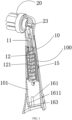
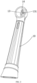
- the electric toothbrush rotating replacement head device includes a toothbrush replacement head body 100, the toothbrush replacement head body 100 includes a toothbrush handle 10 and a toothbrush head 20, and the toothbrush handle 10 defines a cavity 101. Preferably, two ends of the cavity 101 are opened.
- the toothbrush head 20 is disposed on a top of the cavity 101, an inside of the cavity 101 is provided with an elastic connecting rod 11, a bottom of the elastic connecting rod 11 is provided with a spring limiting disc 111, and the elastic connecting rod 11 defines a first pin hole 1171 on the top of the elastic connecting rod 11.
- the first pin hole 1171 is provided with a pin 117 therein, and a diameter of the first pin hole 1171 is greater than a diameter of the pin 117, in other words, the first pin hole 1171 is in a clearance fit with the pin 117.
- the first pin hole 1171 is configured to be connected to an end of the pin 117.
- the elastic connecting rod 11 is provided with a compression spring 12 and disposed in the compression spring 12, and the compression spring 12 is disposed on the spring limiting disc 111.
- the toothbrush head 20 includes a convex block 206, preferably, the convex block 206 is cylindrical.
- the convex block 206 defines a second pin hole 201, a diameter of the second pin hole 201 is basically the same as that of the pin 117.
- the second pin hole 201 is connected to the other end of the pin 117, and the second pin hole 201 is tightly fitted with the other end of the pin 117.
- the elastic connecting rod 11 is inserted into the second pin hole 201 through the pin 117 and connected to the toothbrush head 20.
- the toothbrush handle 10 is a tubular structure with the cavity 101 inside.
- two ends of the cavity 101 are opened for installing the elastic connecting rod 11 inside the toothbrush handle 10.
- the top of the elastic connecting rod 11 extends to a back of the toothbrush head 20, and the top of the elastic connecting rod 11 defines the first pin hole 1171.
- an end of the pin 117 is connected to the first pin hole 1171, and the other end of the pin 117 is connected to the toothbrush head 20 through the second pin hole 201.
- circular hole positions of the second pin hole 201 and the first pin hole 1171 are concentric, and the elastic connecting rod 11 is connected to the toothbrush head 20 through the pin 17.
- the diameter of the first pin hole 1171 is greater than the diameter of the pin 117, in other words, the diameter of the pin 117 is slightly smaller than the diameter of the first pin hole 1171. Therefore, there is a narrow spacing between the first pin hole 1171 and the pin 117, and the first pin hole 1171 and the pin 117 can rotate with each other.
- the toothbrush head 20 is connected to the elastic connecting rod 11 through the pin 117, thereby forming a transmission mechanism configured to convert a linear movement into a rotary oscillation.
- the bottom of the elastic connecting rod 11 is provided with the spring limiting disc 111, the elastic connecting rod 11 is sleeved in the compression spring 12, and the compression spring 12 is disposed on the spring limiting disc 111.
- a front wall of the cavity 101 serves as a limiting surface of a spring sleeve 122, the spring limiting disc 111 limits the compression spring 12 from falling off, and a top surface of the spring limiting disc 111 serves as a driving surface for the rebound of the compression spring 12.
- the spring sleeve 122 defines a spring installation hole 121, the circumferential surface of the spring limiting disc 111 fits with the spring installation hole 121, thereby guiding the compression spring 12, increasing the stability of the reciprocating motion of the elastic connecting rod 11, and reducing noises.
- two sides of the elastic connecting rod 11 are provided with a first spring limiting block 1151 and a second spring limiting block 1152 respectively.
- the first spring limiting block 1151 and the second spring limiting block 1152 are configured to limit the compression spring 12 from falling off, thereby increasing the stability of the reciprocating motion of the compression spring 12.
- the elastic connecting rod 11 defines an installation groove 116 disposed above the first spring limiting block 1151 and the second spring limiting block 1152.
- the installation groove 116 is configured for positioning and assembling precisely.
- a part of the elastic connecting rod 11 from the installation groove 116 to the pin 117 is in a bent shape.
- the elastic connecting rod 11 can be connected to the toothbrush head 20 through the pin 117 more conveniently, and the toothbrush head 20 can be more conveniently combined into a transmission mechanism configured to convert a linear movement into a rotary oscillation, which has a better rotation effect.
- the spring limiting disc 111 defines a vent groove 113, and a cross bone 112 is disposed under the spring limiting disc 111.
- the cross bone 112 is disposed under the elastic connecting rod 11, an end face of the cross bone 112 is a curved surface contact point 114, the curved surface contact point 114 can increase the balance and reliability when the elastic connecting rod 11 contacts with the main body shaft 31 of the main body 30 of the electric toothbrush.
- the main body shaft 31 moves up and down in a reciprocating motion.
- the elastic connecting rod 11 is pushed upwards.
- the elastic connecting rod 11 is compressed by the compression spring 12 and moves down with the main body shaft 31, and thus the elastic connecting rod 11 always move up and down with the main body shaft 31 in a reciprocating motion.
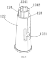
- the elastic connecting rod 11 is disposed in a spring sleeve 122 through the compression spring 12.
- the spring sleeve 122 is installed at the middle of the cavity 101 of the toothbrush handle 10.
- a buckle 1221 is disposed at a side of the spring sleeve 122, the buckle is fitted with a buckle hole 15 in the middle of the cavity 101 of the toothbrush handle 10 to prevent the spring sleeve 122 from falling off from the toothbrush handle 10.
- the spring installation hole 121 can be defined on the spring sleeve 122, and the spring installation hole 121 is a circular through-hole located in the middle of the spring sleeve 122. Furthermore, preferably, there is a sleeve convex block 124 disposed on a top of the spring sleeve 122, and an elastic connecting rod through hole 1241 is defined on the middle of the sleeve convex block 124.
- the elastic connecting rod through hole 1241 can be provided with limiting grooves 1242. The elastic connecting rod 11 passes through the spring sleeve 122 through the elastic connecting rod through hole 1241.
- a spacing between the elastic connecting rod 11 and the spring sleeve 122 is a position for installing the compression spring 12.
- the compression spring 12 is sleeved onto the elastic connecting rod 11 and installed in the spring sleeve 122.
- the first spring limiting block 1151 and the second spring limiting block 1152 on the elastic connecting rod 11 are respectively installed in the limiting grooves 1242 of the spring sleeve 122.
- the force of the compressed spring 12 is borne by the first spring limiting block 1151 and the second spring limiting block 1152, thereby avoiding the deformation of the elastic connecting rod 11 caused by the tension of the compressed spring 12.s
- the elastic connecting rod 11 defines a vent groove 113 which can quickly remove gases from the spring sleeve 122 when the toothbrush replacement head body 100 is working, thereby avoiding power loss.
- the toothbrush head 20 includes a positioning step 207, and the convex block 206 is connected to the toothbrush head 20 through the positioning step 207.
- the toothbrush head 20 includes an inner cylinder 204 disposed in the convex block 206 and a rotating shaft 23 disposed on the inner cylinder 204.
- the inner cylinder 204 includes a rotating shaft hole 209, and the rotating shaft 23 is connected to the inner cylinder 204 through an interference fit between the rotating shaft hole 209 and the rotating shaft 23.
- the toothbrush head 20 includes a first connecting bone 202 and a second connecting bone 205, and the convex block 206 is connected to the inner cylinder 204 through the first connecting bone 202 and the second connecting bone 205.
- a first spacing cavity 203 and a second spacing cavity 208 are provided between the first connecting bone 202 and the second connecting bone 205.
- the top of the cavity 101 is provided with a rotation limiting column 14.
- a rotating shaft through hole 131 is disposed at a side of the rotation limiting column 14.
- a cylinder 13 is disposed on the side of the rotation limiting column 14, and the cylinder 13 defines the rotating shaft through hole 131.
- the positioning step 207 is disposed at a back of the toothbrush head 20, so that the positioning step 207 can be configured to achieve the automatic assembly of the whole of the toothbrush replacement head body 100 and increase a strength of the toothbrush head 20.
- the convex block 206 is disposed at the back of the toothbrush head 20, preferably, the convex block 206 is cylindrical in shape, and the convex block 206 is an outer cylinder, and the inner cylinder 204 is disposed in the middle of the convex block 206.
- the convex block 206 and the inner cylinder 204 are connected to each other through the first connecting bone 202 and the second connecting bone 205, and the first spacing cavity 203 and the second spacing cavity 208 are provided between the convex block 206 and the inner cylinder 204.
- the first spacing cavity 203 and the second spacing cavity 208 are configured to reduce processing difficulty and increase structural strength.
- the first connecting bone 202 defines the second pin hole 201 which is configured for installing the pin 117.
- the second pin hole 201 tightly fits with the other end of the pin 117, and the toothbrush head 20 is connected to the elastic connecting rod 11 through the pin 117.
- the inner cylinder 204 is a rotation center of the toothbrush head 20, and the inner cylinder 204 defines the rotating shaft hole 209.
- the shaft hole 209 is connected to the rotating shaft through hole 131 through the rotating shaft 23.
- the rotating shaft 23 is made of stainless steel.
- the rotating shaft 23 is in an interference fit with the rotating shaft hole 209.
- a front section of the rotating shaft 23 is designed with a multi-layer reverse buckle, and the multi-layer reverse buckle makes the toothbrush handle 10 can be firmly connected to the toothbrush head 20, thereby preventing the generation of friction forces and thrust forces and preventing the toothbrush head 20 and the toothbrush handle 10 from falling off due to the friction forces and thrust forces.
- the rotation limiting column 14 is disposed in the cavity 101 of the toothbrush handle 10. When the toothbrush head 20 is installed, the rotation limiting column 14 is located in the first spacing cavity 203 of the toothbrush head 20. When the toothbrush head 20 rotates, the rotation limiting column 14 is configured to cooperate with the first connecting bone 202 and the second connecting bone 205 to limit a rotation angle of the toothbrush head 20.
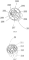
- the toothbrush head 20 includes a bristle top cover 21 and a bristle bottom cover 22.
- the bristle top cover 21 defines bristle holes 213, and the bristle bottom cover 22 defines a glue-overflow groove 223.
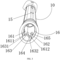
- a bottom of the cavity 101 is provided with an opening 16, a first elastic sheet 161 and a second elastic sheet 162 are disposed in the opening 16, an installation clamping groove 163 is provided between the first elastic sheet 161 and the second elastic sheet 162, and an avoid groove 164 is provided between a side wall 165 of the opening 16 and the second elastic sheet 162.
- the avoid groove 164 is configured to allow the first elastic sheet 161 and the second elastic sheet 162 to deform outward.
- the first elastic sheet 161 defines a first clamping groove 1611 and the second elastic sheet 162 defines a second clamping groove 1612.
- the first clamping groove 1611 and the second clamping groove 1612 are corresponding in position and the same in size and structure.
- the first elastic sheet 161 includes a first reinforcing block 1631
- the second elastic sheet 162 includes a second reinforcing block 1632.
- the toothbrush head 20 is installed on an upper opening (i.e., the top of the cavity 101) of the toothbrush handle 10.
- the disclosure is different from most methods of installing bristles through copper sheets on the market.
- the toothbrush head 20 uses a copper-free bristle planting process to avoid rusting pollution of the copper sheets, reduce bacterial growth, and ensure safety and hygiene.
- the toothbrush head 20 includes the bristle top cover 21 and the bristle bottom cover 22.
- the bristle top cover 21 is provided with a top cover connecting surface 211, hot-melt adhesive nails 212, and the bristle holes 213.
- a front surface of the bristle bottom cover 22 is provided with a bottom cover connecting surface 221, an ultrasonic line 222, and the glue-overflow groove 223.
- bristles 214 are filled in each of the bristle holes 213, and the bristles 214 and the hot-melt glue nails 212 are melted into a whole through a high-temperature hot-melt process, so that the copper-free bristle planting is realized.
- the top cover connecting surface 211 of the bristle top cover 21 fits with the bottom cover connecting surface 221 of the bristle bottom cover 22.
- the bottom cover connecting surface 221 of the bristle bottom cover 22 is provided with the ultrasonic line 222, so that the bristle top cover 21 is configured to be fused with the bristle bottom cover 22 through an ultrasonic technology to assemble the toothbrush head 20.
- an inner side of the bottom cover connecting surface 221 of the bristle bottom cover 22 is provided with the glue-overflow groove 223, the glue-overflow groove is configured to effectively prevent the size of a spacing caused by glue-overflow during the bristle top cover 21 is fused with the bristle bottom cover 22 from increasing.
- the positioning step 207 and the convex block 206 can be disposed on a back surface of the bristle bottom cover 22.
- the bottom of the cavity 101 of the toothbrush handle 10 can be installed and connected on the main body 30 of the electric toothbrush.
- the bottom of the cavity 101 is provided with the opening 16, and the walls on both sides of the opening 16 respectively are provided with the first elastic sheet 161 and the second elastic sheet 162.
- the installation clamping groove 163 is provided between the first elastic sheet 161 and the second elastic sheet 162, and the avoid groove 164 is provided between the second elastic sheet 162 and the side wall 165 of the opening 16.
- the first elastic sheet 161 defines the first clamping groove 1611
- the second elastic sheet 162 defines the second clamping groove 1612.
- the first elastic sheet 161 further includes the first reinforcing block 1631
- the second elastic sheet 162 further includes the second reinforcing block 1632.
- the installation clamping groove 163 and a groove mouth of the avoid groove 164 are chamfered to guide the toothbrush handle 10 to the main body 30 of the electric toothbrush.
- each of the first clamping groove 1611 and the second clamping groove 1612 is in a semi-circular shape.
- the first clamping groove 1611 and the second clamping groove 1612 are configured to fit with main body buckle, thereby preventing the toothbrush handle 10 from falling off.
- the first clamping groove 1611 and the second clamping groove 1612 defines a first clamping position and a second clamping position, and each of the first clamping position and the second clamping position is in a semi-circular shape.
- the installation clamping groove 163 of the toothbrush handle 10 will be stretched, so that the main body buckle 32 can enter the first clamping position and the second clamping position respectively through the installation clamping groove 163 and the avoid groove 164, the first clamping position and the second clamping position on both sides act at the same time to clamp the main body buckle 32, and the toothbrush replacement head body 100 can be reliably assembled with the main body 30 of the electric toothbrush.
- the electric toothbrush rotating replacement head device of the disclosure is driven by an external force (the external force is provided by the main body 30 of the electric toothbrush).
- the rebound of the compression spring 12 is taken as a power source of the device, and the compression spring 12 is configured to drive the toothbrush head 20 through the elastic connecting rod 11 and the pin 117.
- the rotating shaft 23 made of stainless steel is taken as the center to swing back and forth, so as to realize the cleaning effect of the bristles 214 on teeth.
- the electric toothbrush rotating replacement head device of the disclosure optimizes the design of related art, has a simpler structure, a simpler installation, higher transmission efficiency and a better cleaning effect.
Landscapes
- Health & Medical Sciences (AREA)
- Dentistry (AREA)
- Epidemiology (AREA)
- Life Sciences & Earth Sciences (AREA)
- Animal Behavior & Ethology (AREA)
- General Health & Medical Sciences (AREA)
- Public Health (AREA)
- Veterinary Medicine (AREA)
- Brushes (AREA)
Applications Claiming Priority (1)
| Application Number | Priority Date | Filing Date | Title |
|---|---|---|---|
| CN202321285055.2U CN219782796U (zh) | 2023-05-24 | 2023-05-24 | 新型电动牙刷替换头装置 |
Publications (4)
| Publication Number | Publication Date |
|---|---|
| EP4467098A2 true EP4467098A2 (de) | 2024-11-27 |
| EP4467098A3 EP4467098A3 (de) | 2025-02-12 |
| EP4467098B1 EP4467098B1 (de) | 2025-10-15 |
| EP4467098C0 EP4467098C0 (de) | 2025-10-15 |
Family
ID=88182985
Family Applications (1)
| Application Number | Title | Priority Date | Filing Date |
|---|---|---|---|
| EP24177885.1A Active EP4467098B1 (de) | 2023-05-24 | 2024-05-24 | Rotierende ersatzkopfvorrichtung für elektrische zahnbürste |
Country Status (2)
| Country | Link |
|---|---|
| EP (1) | EP4467098B1 (de) |
| CN (1) | CN219782796U (de) |
Families Citing this family (3)
| Publication number | Priority date | Publication date | Assignee | Title |
|---|---|---|---|---|
| ES3038992T3 (en) | 2022-01-31 | 2025-10-16 | Braun Gmbh | Attachment for an oral care device handle and oral care device comprising the attachment |
| US12090015B1 (en) * | 2023-11-27 | 2024-09-17 | Mingfeng Li | Electric toothbrush replacement head device |
| CN221866084U (zh) * | 2023-11-30 | 2024-10-22 | 杨计喜 | 电动口腔清洁工具 |
Family Cites Families (2)
| Publication number | Priority date | Publication date | Assignee | Title |
|---|---|---|---|---|
| DE19717334C1 (de) * | 1997-04-24 | 1998-07-09 | Braun Ag | Bürstenteil für eine elektrische Zahnbürste |
| CN114557788A (zh) * | 2022-03-22 | 2022-05-31 | 深圳市雅贝康科技有限公司 | 一种替换刷头及口腔卫生装置 |
-
2023
- 2023-05-24 CN CN202321285055.2U patent/CN219782796U/zh active Active
-
2024
- 2024-05-24 EP EP24177885.1A patent/EP4467098B1/de active Active
Also Published As
| Publication number | Publication date |
|---|---|
| EP4467098B1 (de) | 2025-10-15 |
| CN219782796U (zh) | 2023-10-03 |
| EP4467098C0 (de) | 2025-10-15 |
| EP4467098A3 (de) | 2025-02-12 |
Similar Documents
| Publication | Publication Date | Title |
|---|---|---|
| EP4467098A2 (de) | Rotierende ersatzkopfvorrichtung für elektrische zahnbürste | |
| GB2630398A (en) | Electric toothbrush rotating replacement head device | |
| US11896116B1 (en) | Electric toothbrush rotating replacement head device | |
| CN1306915C (zh) | 电动牙刷 | |
| CN103068337B (zh) | 用于偏心重量驱动的个人护理器具的柔性驱动轴 | |
| US12303019B2 (en) | Replacement brush head and oral hygiene device | |
| EP1734889B1 (de) | Einweg-kopfteil für eine nodal montierte zahnbürste | |
| RU2577941C2 (ru) | Сменная головка для электрической зубной щетки | |
| JP2014503271A (ja) | ウェッジとバネハンドルインターフェースとを備える動力歯ブラシ用のブラシヘッド | |
| EP4566482A1 (de) | Ersatzkopfvorrichtung für elektrische zahnbürste | |
| US20230277022A1 (en) | Cleaning brush and intelligent cleaning device having the same | |
| CA2510133A1 (en) | System for removably joining a driven member to a driven member with workpiece | |
| EP4248909B1 (de) | Ersatzbürstenkopf und mundhygienevorrichtung | |
| US20220160119A1 (en) | U-shaped electric toothbrush | |
| EP4570123A1 (de) | Ersatzkopfvorrichtung für elektrische zahnbürste | |
| US12127900B1 (en) | Electric toothbrush rotating replacement head device | |
| CN214761571U (zh) | 一种电动牙刷 | |
| RU223863U1 (ru) | Узел вращающейся головки для электрической зубной щетки | |
| CN217611435U (zh) | 打击装置 | |
| GB2636779A (en) | Electric toothbrush rotating replacement head device | |
| CN220653177U (zh) | 一种电动牙刷的电机 | |
| CN217138328U (zh) | 电动牙刷 | |
| CN211023246U (zh) | 一种便于更换刷毛结构的牙刷头 | |
| US20250241736A1 (en) | Electric toothbrush head and electric toothbrush | |
| CN223586067U (zh) | 牙刷头及电动牙刷 |
Legal Events
| Date | Code | Title | Description |
|---|---|---|---|
| PUAI | Public reference made under article 153(3) epc to a published international application that has entered the european phase |
Free format text: ORIGINAL CODE: 0009012 |
|
| STAA | Information on the status of an ep patent application or granted ep patent |
Free format text: STATUS: REQUEST FOR EXAMINATION WAS MADE |
|
| 17P | Request for examination filed |
Effective date: 20240524 |
|
| AK | Designated contracting states |
Kind code of ref document: A2 Designated state(s): AL AT BE BG CH CY CZ DE DK EE ES FI FR GB GR HR HU IE IS IT LI LT LU LV MC ME MK MT NL NO PL PT RO RS SE SI SK SM TR |
|
| PUAL | Search report despatched |
Free format text: ORIGINAL CODE: 0009013 |
|
| STAA | Information on the status of an ep patent application or granted ep patent |
Free format text: STATUS: EXAMINATION IS IN PROGRESS |
|
| AK | Designated contracting states |
Kind code of ref document: A3 Designated state(s): AL AT BE BG CH CY CZ DE DK EE ES FI FR GB GR HR HU IE IS IT LI LT LU LV MC ME MK MT NL NO PL PT RO RS SE SI SK SM TR |
|
| RIC1 | Information provided on ipc code assigned before grant |
Ipc: A61C 17/34 20060101ALI20250107BHEP Ipc: A61C 17/32 20060101AFI20250107BHEP |
|
| 17Q | First examination report despatched |
Effective date: 20250124 |
|
| GRAP | Despatch of communication of intention to grant a patent |
Free format text: ORIGINAL CODE: EPIDOSNIGR1 |
|
| STAA | Information on the status of an ep patent application or granted ep patent |
Free format text: STATUS: GRANT OF PATENT IS INTENDED |
|
| INTG | Intention to grant announced |
Effective date: 20250602 |
|
| GRAS | Grant fee paid |
Free format text: ORIGINAL CODE: EPIDOSNIGR3 |
|
| GRAA | (expected) grant |
Free format text: ORIGINAL CODE: 0009210 |
|
| STAA | Information on the status of an ep patent application or granted ep patent |
Free format text: STATUS: THE PATENT HAS BEEN GRANTED |
|
| AK | Designated contracting states |
Kind code of ref document: B1 Designated state(s): AL AT BE BG CH CY CZ DE DK EE ES FI FR GB GR HR HU IE IS IT LI LT LU LV MC ME MK MT NL NO PL PT RO RS SE SI SK SM TR |
|
| REG | Reference to a national code |
Ref country code: GB Ref legal event code: FG4D Ref country code: CH Ref legal event code: F10 Free format text: ST27 STATUS EVENT CODE: U-0-0-F10-F00 (AS PROVIDED BY THE NATIONAL OFFICE) Effective date: 20251015 |
|
| REG | Reference to a national code |
Ref country code: IE Ref legal event code: FG4D |
|
| REG | Reference to a national code |
Ref country code: DE Ref legal event code: R096 Ref document number: 602024000930 Country of ref document: DE |
|
| U01 | Request for unitary effect filed |
Effective date: 20251105 |
|
| U07 | Unitary effect registered |
Designated state(s): AT BE BG DE DK EE FI FR IT LT LU LV MT NL PT RO SE SI Effective date: 20251111 |
|
| PG25 | Lapsed in a contracting state [announced via postgrant information from national office to epo] |
Ref country code: ES Free format text: LAPSE BECAUSE OF FAILURE TO SUBMIT A TRANSLATION OF THE DESCRIPTION OR TO PAY THE FEE WITHIN THE PRESCRIBED TIME-LIMIT Effective date: 20251015 |
|
| PG25 | Lapsed in a contracting state [announced via postgrant information from national office to epo] |
Ref country code: NO Free format text: LAPSE BECAUSE OF FAILURE TO SUBMIT A TRANSLATION OF THE DESCRIPTION OR TO PAY THE FEE WITHIN THE PRESCRIBED TIME-LIMIT Effective date: 20260115 |
|
| PG25 | Lapsed in a contracting state [announced via postgrant information from national office to epo] |
Ref country code: HR Free format text: LAPSE BECAUSE OF FAILURE TO SUBMIT A TRANSLATION OF THE DESCRIPTION OR TO PAY THE FEE WITHIN THE PRESCRIBED TIME-LIMIT Effective date: 20251015 |
|
| PG25 | Lapsed in a contracting state [announced via postgrant information from national office to epo] |
Ref country code: RS Free format text: LAPSE BECAUSE OF FAILURE TO SUBMIT A TRANSLATION OF THE DESCRIPTION OR TO PAY THE FEE WITHIN THE PRESCRIBED TIME-LIMIT Effective date: 20260115 |
|
| PG25 | Lapsed in a contracting state [announced via postgrant information from national office to epo] |
Ref country code: IS Free format text: LAPSE BECAUSE OF FAILURE TO SUBMIT A TRANSLATION OF THE DESCRIPTION OR TO PAY THE FEE WITHIN THE PRESCRIBED TIME-LIMIT Effective date: 20260215 |