EP4467056A1 - Automatic cleaning apparatus - Google Patents
Automatic cleaning apparatus Download PDFInfo
- Publication number
- EP4467056A1 EP4467056A1 EP23909645.6A EP23909645A EP4467056A1 EP 4467056 A1 EP4467056 A1 EP 4467056A1 EP 23909645 A EP23909645 A EP 23909645A EP 4467056 A1 EP4467056 A1 EP 4467056A1
- Authority
- EP
- European Patent Office
- Prior art keywords
- brush
- end portion
- rolling
- rolling brush
- brush part
- Prior art date
- Legal status (The legal status is an assumption and is not a legal conclusion. Google has not performed a legal analysis and makes no representation as to the accuracy of the status listed.)
- Pending
Links
Images













Classifications
-
- A—HUMAN NECESSITIES
- A47—FURNITURE; DOMESTIC ARTICLES OR APPLIANCES; COFFEE MILLS; SPICE MILLS; SUCTION CLEANERS IN GENERAL
- A47L—DOMESTIC WASHING OR CLEANING; SUCTION CLEANERS IN GENERAL
- A47L11/00—Machines for cleaning floors, carpets, furniture, walls, or wall coverings
- A47L11/40—Parts or details of machines not provided for in groups A47L11/02 - A47L11/38, or not restricted to one of these groups, e.g. handles, arrangements of switches, skirts, buffers, levers
- A47L11/4036—Parts or details of the surface treating tools
- A47L11/4041—Roll shaped surface treating tools
-
- A—HUMAN NECESSITIES
- A46—BRUSHWARE
- A46B—BRUSHES
- A46B13/00—Brushes with driven brush bodies or carriers
- A46B13/001—Cylindrical or annular brush bodies
- A46B13/005—Cylindrical or annular brush bodies made up of a series of longitudinal strips or segments
-
- A—HUMAN NECESSITIES
- A46—BRUSHWARE
- A46B—BRUSHES
- A46B13/00—Brushes with driven brush bodies or carriers
- A46B13/02—Brushes with driven brush bodies or carriers power-driven carriers
-
- A—HUMAN NECESSITIES
- A47—FURNITURE; DOMESTIC ARTICLES OR APPLIANCES; COFFEE MILLS; SPICE MILLS; SUCTION CLEANERS IN GENERAL
- A47L—DOMESTIC WASHING OR CLEANING; SUCTION CLEANERS IN GENERAL
- A47L1/00—Cleaning windows
- A47L1/02—Power-driven machines or devices
-
- A—HUMAN NECESSITIES
- A47—FURNITURE; DOMESTIC ARTICLES OR APPLIANCES; COFFEE MILLS; SPICE MILLS; SUCTION CLEANERS IN GENERAL
- A47L—DOMESTIC WASHING OR CLEANING; SUCTION CLEANERS IN GENERAL
- A47L11/00—Machines for cleaning floors, carpets, furniture, walls, or wall coverings
- A47L11/02—Floor surfacing or polishing machines
- A47L11/10—Floor surfacing or polishing machines motor-driven
- A47L11/14—Floor surfacing or polishing machines motor-driven with rotating tools
- A47L11/18—Floor surfacing or polishing machines motor-driven with rotating tools the tools being roll brushes
- A47L11/19—Parts or details of the brushing tools
-
- A—HUMAN NECESSITIES
- A47—FURNITURE; DOMESTIC ARTICLES OR APPLIANCES; COFFEE MILLS; SPICE MILLS; SUCTION CLEANERS IN GENERAL
- A47L—DOMESTIC WASHING OR CLEANING; SUCTION CLEANERS IN GENERAL
- A47L11/00—Machines for cleaning floors, carpets, furniture, walls, or wall coverings
- A47L11/24—Floor-sweeping machines, motor-driven
-
- A—HUMAN NECESSITIES
- A47—FURNITURE; DOMESTIC ARTICLES OR APPLIANCES; COFFEE MILLS; SPICE MILLS; SUCTION CLEANERS IN GENERAL
- A47L—DOMESTIC WASHING OR CLEANING; SUCTION CLEANERS IN GENERAL
- A47L11/00—Machines for cleaning floors, carpets, furniture, walls, or wall coverings
- A47L11/28—Floor-scrubbing machines, motor-driven
- A47L11/282—Floor-scrubbing machines, motor-driven having rotary tools
-
- A—HUMAN NECESSITIES
- A47—FURNITURE; DOMESTIC ARTICLES OR APPLIANCES; COFFEE MILLS; SPICE MILLS; SUCTION CLEANERS IN GENERAL
- A47L—DOMESTIC WASHING OR CLEANING; SUCTION CLEANERS IN GENERAL
- A47L9/00—Details or accessories of suction cleaners, e.g. mechanical means for controlling the suction or for effecting pulsating action; Storing devices specially adapted to suction cleaners or parts thereof; Carrying-vehicles specially adapted for suction cleaners
- A47L9/02—Nozzles
- A47L9/04—Nozzles with driven brushes or agitators
- A47L9/0455—Bearing means therefor
-
- A—HUMAN NECESSITIES
- A47—FURNITURE; DOMESTIC ARTICLES OR APPLIANCES; COFFEE MILLS; SPICE MILLS; SUCTION CLEANERS IN GENERAL
- A47L—DOMESTIC WASHING OR CLEANING; SUCTION CLEANERS IN GENERAL
- A47L9/00—Details or accessories of suction cleaners, e.g. mechanical means for controlling the suction or for effecting pulsating action; Storing devices specially adapted to suction cleaners or parts thereof; Carrying-vehicles specially adapted for suction cleaners
- A47L9/02—Nozzles
- A47L9/04—Nozzles with driven brushes or agitators
- A47L9/0461—Dust-loosening tools, e.g. agitators, brushes
- A47L9/0466—Rotating tools
- A47L9/0477—Rolls
-
- A—HUMAN NECESSITIES
- A47—FURNITURE; DOMESTIC ARTICLES OR APPLIANCES; COFFEE MILLS; SPICE MILLS; SUCTION CLEANERS IN GENERAL
- A47L—DOMESTIC WASHING OR CLEANING; SUCTION CLEANERS IN GENERAL
- A47L9/00—Details or accessories of suction cleaners, e.g. mechanical means for controlling the suction or for effecting pulsating action; Storing devices specially adapted to suction cleaners or parts thereof; Carrying-vehicles specially adapted for suction cleaners
- A47L9/02—Nozzles
- A47L9/04—Nozzles with driven brushes or agitators
- A47L9/0461—Dust-loosening tools, e.g. agitators, brushes
- A47L9/0488—Combinations or arrangements of several tools, e.g. edge cleaning tools
-
- A—HUMAN NECESSITIES
- A46—BRUSHWARE
- A46B—BRUSHES
- A46B2200/00—Brushes characterized by their functions, uses or applications
- A46B2200/30—Brushes for cleaning or polishing
- A46B2200/3033—Household brush, i.e. brushes for cleaning in the house or dishes
-
- A—HUMAN NECESSITIES
- A47—FURNITURE; DOMESTIC ARTICLES OR APPLIANCES; COFFEE MILLS; SPICE MILLS; SUCTION CLEANERS IN GENERAL
- A47L—DOMESTIC WASHING OR CLEANING; SUCTION CLEANERS IN GENERAL
- A47L2201/00—Robotic cleaning machines, i.e. with automatic control of the travelling movement or the cleaning operation
-
- A—HUMAN NECESSITIES
- A47—FURNITURE; DOMESTIC ARTICLES OR APPLIANCES; COFFEE MILLS; SPICE MILLS; SUCTION CLEANERS IN GENERAL
- A47L—DOMESTIC WASHING OR CLEANING; SUCTION CLEANERS IN GENERAL
- A47L2201/00—Robotic cleaning machines, i.e. with automatic control of the travelling movement or the cleaning operation
- A47L2201/02—Docking stations; Docking operations
Definitions
- the second filler 250 may be made of, for example, a rigid material such as hard plastic, a hard resin material and a metal material, which are not exhaustive.
- the second filler 250 may also be a hollowed-out material or structure having the same incompressibility, such as an incompressible keel structure to reduce the weight of the second rolling brush, which is not exhaustive here.
- the second filler 250 and the second shaft lever 240 may be integrally molded into an integrated structure from a hard material so as to reduce the running clearance.
- the first rolling brush 100 and the second rolling brush 200 rotate at the same speed and in different directions, for example, the first rolling brush 100 rotates counterclockwise and the second rolling brush 200 rotates clockwise.
- the first brush parts and the second brushs part are always in an interference contact state in the middle position, that is, a next layer of brush parts has been in contact before a previous layer of brush parts is separated; and as the rotation continues, the previous layer of brush parts is separated, and the brush parts at two ends on the next layer are in contact to form a diamond-shaped closed air path in the middle.
- the brush parts may collect the garbage to the middle, so that the garbage may be sucked into the dust box in the device along an air duct 5400, thereby achieving the purpose of cleaning.
- the diamond-shaped closed air path formed by the next layer of brush parts may gradually become smaller until current closed sweeping is finished.
- the next closed sweeping may start immediately, i.e., the brush parts at two ends of another next layer may be in contact to form a diamond-shaped closed air path in the middle, and so on.
- the first rolling brush and the second rolling brush can achieve the effect of constant sweeping to further improve the sweeping efficiency.
- a surface of the second brush part 232 is provided with a plurality of second bumps 2321.
- the plurality of second bumps on the second brush part 232 are uniformly distributed in an extension direction of the surface of the second brush part 232, and can increase the friction between the brush member and the garbage so as to achieve thorough sweeping.
- the external diameter of the second shaft component is less than the external diameter of the first filler, and/or the external diameter of the second shaft component is greater than the internal diameter of the first filler. Since the second rolling brush is of an incompressible hard-core structure, in order to avoid a great decrease in passability of the large-particle garbage due to the incompressible hard-core structure, it is necessary to set a blade of the second rolling brush to be longer than that of the first rolling brush, and the distance between the external diameter of the second shaft component (hard core) of the second rolling brush and the floor to be not less than the distance between the external direction of the first filler (soft core) of the first rolling brush and the floor.
- the external diameter of the second shaft component is less than that of the first filler.
- the external diameter of the second shaft component (hard core) of the second rolling brush is too large, a flexible space, which allows the garbage to pass through, between the front and rear rolling brushes may become smaller, and the slightly large hard garbage may get stuck between the first rolling brush and the second rolling brush.
- the external diameter of the second shaft component (hard core) of the second rolling brush is further reduced, when the first brush part of the first rolling brush and the second brush part of the second rolling brush have the same outer contour diameter, correspondingly, the length of the second brush part may gradually increase with the decrease of the external diameter of the second shaft component (hard core).
- the second brush part should not be too long, at this time, the external diameter of the corresponding second shaft component (hard core) should not be too small, and it is possible to make the external diameter of the second shaft component greater than the internal diameter of the first filler, so as to ensure that the length of the second brush part is within an appropriate range.
- a plane where the lowest point of the first filler is located is lower than a plane where the lowest point of the second shaft component is located. Since the first filler is compressible, in order to ensure the passability of the garbage under the first rolling brush and the second rolling brush, it is necessary to make the plane where the lowest point of the first filler is located lower than the plane where the lowest point of the second shaft component is located.
- the first rolling brush is the front rolling brush
- the passability of the garbage can be guaranteed since the first filler is compressible.
- the second rolling brush is the front rolling brush
- the passability of the garbage can still be guaranteed since the lowest point of the second shaft component is relatively high. Meanwhile, since the first rolling brush is the rear rolling brush and is relatively close to the floor, the garbage can be intercepted and is less likely to leak underneath the first rolling brush, which improves the cleaning efficiency of the cleaning device.
- the amount of interference between the first brush part and the floor may be greatly increased, which increases noise caused by the fact that first brush part flaps the floor, and also increases resistance to advancing of the automatic cleaning device. This is inconvenient for the automatic cleaning device to perform the cleaning task.
- an outer contour formed by the maximum distance by which the first brush part extends from the outer surface of the first cylindrical member in the direction away from the first cylindrical member forms the external diameter of the first rolling brush
- an outer contour formed by the maximum distance by which the second brush part extends from the outer surface of the second cylindrical member in the direction away from the second cylindrical member forms the external diameter of the second rolling brush
- the external diameter of the first rolling brush is substantially equal to that of the second rolling brush.
- the dual rolling brushes in a folded state can be stored substantially flatly in the cleaning module, which also reduces the design and processing complexity caused by the inconsistency of design between the front cleaning brush mounting position and the rear cleaning brush mounting position.
- the distance between the axis center of the first rolling brush and the axis center of the second rolling brush is not greater than the external diameter of the first rolling brush and/or the second rolling brush, for example, the distance between the axis center of the first rolling brush and the axis center of the second rolling brush is less than the external diameter of the first rolling brush and/or the second rolling brush.
- the external diameter of the first rolling brush and/or the second rolling brush is approximately equal and the distance between the axis center of the first rolling brush and the axis center of the second rolling brush is greater than the external diameter of the first rolling brush and/or the second rolling brush, there may be no interference between the first brush part and the second brush part, so that the garbage swept to a position between the first rolling brush and the second rolling brush cannot be rolled up smoothly, which affects the overall cleaning effect of the cleaning device.
- an outer contour formed by the maximum distance by which the first brush part extends from the outer surface of the first cylindrical member in the direction away from the first cylindrical member forms the external diameter of the first rolling brush
- an outer contour formed by the maximum distance by which the second brush part extends from the outer surface of the second cylindrical member in the direction away from the second cylindrical member forms the external diameter of the second rolling brush
- the distance between the axis center of the first rolling brush and the axis center of the second rolling brush is not greater than half of the sum of the external diameters of the first rolling brush and the second rolling brush.
- the distance between the axis center of the first rolling brush and the axis center of the second rolling brush is less than half of the sum of the external diameters of the first rolling brush and the second rolling brush.
- the external diameter of the first rolling brush and/or the second rolling brush is unequal, and the distance between the axis center of the first rolling brush and the axis center of the second rolling brush is greater than half of the sum of the external diameters of the first rolling brush and the second rolling brush, there may be no interference between the first brush part and the second brush part, so that the garbage swept to a position between the first rolling brush and the second rolling brush cannot be rolled up smoothly, which affects the overall cleaning effect of the cleaning device.
- a minimum distance between the internal diameter of the first filler and the external diameter of the second shaft component is greater than the difference between the internal diameter and the external diameter of the first filler.
- the first filler and the second shaft component block suction of the fan for the garbage, which may greatly reduce the effect of the garbage entering and leaving the dust box and reduce the cleaning efficiency.
- the first rolling brush and the second rolling brush are arranged front and back in an advancing direction of the automatic cleaning device.
- a dual-brush assembly structure with a front soft brush and a rear hard brush is formed.
- the second rolling brush and the first rolling brush are arranged front and back in an advancing direction of the automatic cleaning device.
- a dual-brush assembly structure with a front hard brush and a rear soft brush is formed.
- the automatic cleaning device by providing the dual-rolling-brush structure including the first rolling brush and the second rolling brush and arranging the first filler in the first rolling brush as an elastic member and the second shaft component in the second rolling brush as a rigid member, the automatic cleaning device can effectively clean the floor based on the two types of rolling brushes, i.e., soft and hard rolling brushes, so that the passability of the garbage between the first rolling brush and the second rolling brush is improved. Moreover, the amounts of interference between the two types of rolling brushes, i.e., soft and hard rolling brushes, and the floor are reasonably configured such that the floor cleaning efficiency is improved on the whole.
- the specific structure of the first rolling brush (also known as a soft brush or a cleaning brush) as described above will be described in detail below with reference to FIGS. 7-12 .
- the same structure and function have the same technical effect, which will not be repeated herein.
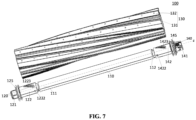
- FIG. 7 is an exploded view of a stereoscopic structure of an example of a cleaning brush according to the present disclosure.
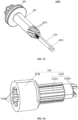
- FIG. 8 is a stereoscopic structural diagram of an example of an end portion member of the cleaning brush of FIG. 7 .
- FIG. 9 is a stereoscopic structural diagram of the end portion member of the cleaning brush of FIG. 8 from another perspective.
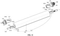
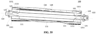
- the cleaning brush 100 includes a shaft lever 110 and a first end portion member 120.
- the shaft lever includes a shaft lever main body 113, and a first end portion 111 and a second end portion 112 located on two sides of the shaft lever main body 113.
- the first end portion member 120 is configured to be mounted on the first end portion 111.
- a side of the first end portion member 120 away from the shaft lever 110 is provided with a first assembly structure 121.
- the first assembly structure 121 is a transmission structure, and the first assembly structure 121 is connected to a driving mechanism of a cleaning device.
- the first end portion member 120 is provided with at least one first lead-in portion 1221.
- the first end portion 111 is provided with at least one first matching portion 1111.
- the at least one first lead-in portion 1221 matches the at least one first matching portion 1111 to form a guiding fit structure such that the first end portion member 120 may only be mounted on the first end portion 111 in one circumferential assembly mode, i.e., the first end portion member 120 and the shaft lever 110 are assembled in a single mounting direction.
- the circumferential assembly mode means that two assembly parts rotate by 360 degrees relative to each other. If there are N assembly modes, it is believed that the two assembly parts have N circumferential assembly modes, where N is greater than or equal to 1.
- the first end portion member 120 includes a first guide sleeve 122, the first guide sleeve 122 is configured to accommodate the first end portion 111, and the at least one first lead-in portion 1221 is arranged on an inner peripheral wall of the first guide sleeve 122, and is a projection protruding inward from the inner peripheral wall of the first guide sleeve 122.
- the first end portion member 120 is mounted on the first end portion 111 on a driving side.
- the at least one first lead-in portion 1221 extends spirally in the circumferential direction of the first guide sleeve 122 in a direction away from the first assembly structure 121, and is specifically in a spiral shape that rotates and extends spirally along an inner peripheral wall, so that the first lead-in portion 1221 has a direction of rotation, for example, a direction of clockwise (or counterclockwise) rotation about an axis z of the shaft lever 110.
- the first lead-in portion 1221 is the projection protruding from the inner peripheral wall of the first guide sleeve 122, which is not limited thereto as long as one of the first lead-in portion 1221 and the first matching portion 1111 is a projection and the other is a recess.
- first lead-in portions 1221 there are two first lead-in portions 1221, and the two first lead-in portions 1221 are of different dimensions.
- the two first lead-in portions 1221 are of different dimensions.
- first lead-in portions 1221 there are two first lead-in portions 1221, which is not limited thereto. In other examples, there may be three or more first lead-in portions 1221.
- the above example is only taken as an optional example for illustration and cannot be construed as a limitation to the present disclosure.
- a first matching portion 1111 corresponding to the first lead-in portion 1221 is arranged on an outer periphery of the first end portion 111 of the shaft lever 110.
- two first matching portions 1111 are arranged on the outer periphery of the first end portion 111, and are in one-to-one correspondence with the two first lead-in portions 1221 respectively.
- the first matching portion 1111 is a groove portion recessed inward from the outer peripheral surface of the first end portion 111, and the first lead-in portion 1221 matches the first matching portion 1111 to form a guiding fit structure, so that the first end portion member 120 can only be mounted on the first end portion 111 in one circumferential assembly mode.
- first lead-in portions of different dimensions By adding the two first lead-in portions of different dimensions to the inner peripheral wall of the first guide sleeve, lead-in mounting can be carried out more effectively.
- first end portion member can only be mounted on the first end portion in one circumferential assembly mode such that the simplicity in mounting the end portion member can be improved, and the stability of the mounting structure can be enhanced.
- the outer periphery of the first guide sleeve 122 is provided with a marking portion 1223 (see FIG. 8 ), which is configured to mark the outer periphery of the first guide sleeve 122 with the position of the first lead-in portion 1221, for indicating a direction of rotational assembly in which the first end portion member 120 is mounted on the first end portion 111 of the shaft lever 110, so that the first lead-in portion 1221 is assembled in alignment with the first matching portion 1111.
- the first guide sleeve 122 is provided with a first locking portion 1222, for example, a groove portion recessed inward from the outer peripheral surface of the first guide sleeve 122.
- the first end portion 111 is provided with a first locking matching portion 1112, and the first locking portion 1222 and the first locking matching portion 1112 cooperate to lock the first end portion member 120 to the first end portion 111.
- the first end portion member 120 further includes a first guide shaft 123, the first guide shaft 123 extends along the axis of the first guide sleeve 122, an end face of the first end portion 111 away from the second end portion 112 is provided with a first guide hole 1113, and the first guide hole 1113 is coaxial with the shaft lever 110 and is configured to accommodate the first guide shaft 123.
- an end face of the first assembly structure 121 away from the shaft lever takes the shape of a regular polygon, and the number of sides of the regular polygon is a divisor of the number of the brush parts.
- the number of sides of the regular polygon of the outer end face of the first end portion member has a corresponding relationship with the number of groups of the brush parts of the automatic cleaning device.
- the number N of sides of the regular polygon is a divisor of the number of groups (for example, 4 sides and 8 groups of blades; for example, 4 sides and 4 groups of blades).
- the regular polygon has N straight sides, which is not limited thereto.
- the sides may be adjusted, for example, the sides are curved sides, or a combination of straight sides and curved sides.
- the shape of the regular polygon can be adaptively changed according to the number of the brush parts.
- the cleaning brush 100 further includes a brush member 130 coaxial with the shaft lever 110.
- the brush member 130 includes: a cylindrical member 131 sleeving the shaft lever; and a plurality of brush parts 132.
- the plurality of brush parts 132 extend from the outer surface of the cylindrical member in a direction away from the cylindrical member 131, and are uniformly arranged in the circumferential direction of the cylindrical member.
- the brush parts 132 include a first brush part.
- the first brush part is V-shaped, and five groups of first brush parts are included.
- the brush parts may further include a second brush part or a third brush part or the like.
- the second brush part and the third brush are different from the first brush part in shape and length.
- different groups of brush parts are of substantially the same structure, and each group of brush parts may include one or more blades. When multiple blades are included, the structures of the multiple blades are always not exactly the same.
- a flexible filler (not shown) is filled between the brush member 130 and the shaft lever 110, and the flexible filler wraps the outer periphery of the shaft lever main body and exposes the first end portion and the second end portion.
- the first end portion member 120 further includes a first blocking structure 125 arranged between the first assembly structure 121 and the first guide sleeve 122 and configured to prevent over-extension of an entanglement away from both of the brush member and the cleaning brush.
- the first blocking structure 125 is, for example, at least one blocking ring, and in this example, two blocking rings.
- the first blocking structure 125 includes a first wall, a sunken portion and a second wall from outside to inside in the axial direction of the cleaning brush, wherein the thickness of the first wall is greater than that of the second wall.
- the entanglement for example, the garbage
- the entanglement can wind the blocking structure of the first end portion member, so that the entanglement can be effectively prevented from winding the shaft lever, and the entanglement can be directly taken down with the disassembly of an end cap member when the end portion member is disassembled.
- the first lead-in portion in the first guide sleeve of the first end portion member and the end portion of the shaft lever on the driving side form the guiding fit structure
- the first locking portion on the first guide sleeve cooperates with the first locking matching portion at the end portion of the shaft lever to form a locking fit structure
- the guiding fit structure and the locking fit structure can assist and cooperate with each other to realize a more effective mounting structure, so that the mounting structure of the end portion member and the shaft lever can be further optimized, which in turn optimizes the overall structure of the cleaning brush.
- FIG. 11 is an exploded view of a stereoscopic structure of the cleaning brush of FIG. 7 from another perspective.
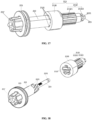
- FIG. 12 is an exploded view of a local structure of a second end portion member and the shaft lever of the cleaning brush of FIG. 7 from one perspective.
- the cleaning brush 100 further includes a second end portion member 140.
- the second end portion member 140 is located on a driven side and mounted on the second end portion 112 of the shaft lever 110.
- a side of the second end portion member 140 away from the shaft lever 110 is provided with a second assembly structure 141 (specifically, a bearing structure).
- the second assembly structure 141 may rotate relative to the shaft lever, and the second end portion member 140 is rotationally connected to other structures (for example, a body) of the cleaning device through the second assembly structure.
- the second end portion member 140 is provided with at least one second lead-in portion 1421.
- the second end portion 112 is provided with at least one second matching portion 1121.
- the at least one second lead-in portion 1421 matches the at least one second matching portion 1121 to form a guiding fit structure such that the second end portion member 140 may be mounted on the second end portion in multiple circumferential assembly modes.
- the second lead-in portion 1421 extends spirally along a circumferential direction of a second guide sleeve 142 in a direction away from the second assembly structure 141, and is specifically in a spiral shape that rotates and extends spirally along an inner peripheral wall, so that the second lead-in portion 1421 has a direction of rotation, for example, a direction of clockwise (or counterclockwise) rotation about the axis z of the shaft lever 110, thereby forming a second lead-in direction.
- the second lead-in direction is the same as a first lead-in direction.
- first lead-in direction and the second lead-in direction are the same, which is not limited thereto.
- the direction of rotation of the first lead-in portion may also be, for example, non-spiral or linear.
- second lead-in direction and the first lead-in direction may also be different. The above example is taken only as an optional example for illustration and cannot be construed as a limitation to the present disclosure.
- the at least one second lead-in portion 1421 includes two second lead-in portions 1421, and the two second lead-in portions 1421 are in the same shape and of the same dimension, so that the second end portion member may be mounted on the second end portion 112 in two circumferential assembly modes.
- the two first lead-in portions 1221 are of different dimensions (correspondingly, the first matching portion 1111 and the second matching portion 1121 are of different dimensions), the two second lead-in portions 1421 are of the same dimension, and the dimensions of the second lead-in portions 1421 lie between the dimensions of two first lead-in portions 1221.
- the dimensions of the two second lead-in portions on the driven side lie between the dimensions of the two first lead-in portions on the driving side, it is possible to ensure that the second end portion member can be freely mounted at multiple angles and that the end portion members on the two sides may not be misplaced, and thus it is possible to effectively ensure that components, for example, the blades, are oriented correctly after the cleaning brush is mounted.
- the second lead-in portions there may be three or more second lead-in portions, and the above example is only taken as an optional example for illustration and should not be construed as a limitation to the present disclosure.
- the two first lead-in portions of different dimensions are arranged on the driving side since the driving side has a requirement for the mounting angle, whereas the second end portion member on the driven side does not need a different-dimension design since the second assembly structure (specifically, a bearing structure) on the driven side can freely rotate relative to the shaft lever.
- the second assembly structure specifically, a bearing structure
- the second lead-in portions may also be of the same dimension.
- the driving side has a relatively fixed mounting direction by setting the lead-in portions of the end portion members on the driving side to have a unique circumferential assembly mode, which is conductive to control on the mounting angles of the rolling brushes and is particularly beneficial in some scenarios where some preset requirements are placed on the orientation or alignment direction of sub-components of the rolling brushes, especially the blades, for example, those scenarios where two rolling brushes in this case are adopted to form a dual-brush system and some alignment requirements are placed on their respective blades.
- the number of sides of the regular polygon of the outer end face of the first end portion member is a divisor of the number of groups of the brush parts of the automatic cleaning device.
- the entanglement can directly wind the blocking structure of the end portion member, so that the entanglement can be effectively prevented from winding the shaft lever.
- the specific structure of the second rolling brush (also known as a hard brush or a cleaning brush) as described above will be described in detail below with reference to FIGS. 13-21 .
- the same structure and function have the same technical effect, which will not be repeated herein.
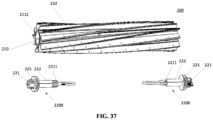
- the cleaning brush 200 includes a shaft lever 210, a brush member 230 and an end portion member 2200.
- the shaft lever has a first end portion 211 and a second end portion 212 that are opposite to each other in an axial direction, and at least one of the first end portion 211 and the second end portion 212 includes a matching part 213.
- the brush member 230 coaxially sleeves the shaft lever 210.
- the end portion member is configured to be fitted with the matching part 213, and a side of the end portion member 2200 away from the matching part 213 is provided with an assembly structure 221.
- At least one of the first end portion and the second end portion of the shaft lever is provided with an accommodating space.
- At least part of the shaft lever is of a solid structure.
- the accommodating space includes a first space segment, and the first space segment is configured to accommodate at least part of a guide rod.
- the accommodating space further includes a second space segment.
- the guide rod is provided with a guiding portion.
- the second space segment is of a structure matching the shape of the guiding portion of the guide rod, so as to be connected to the guiding portion in a matching manner.
- the accommodating space further includes a third space segment.
- the end portion member is further provided with a guide shaft.
- the third space segment is configured to accommodate at least part of the guide shaft.
- An internal diameter of the first space segment is greater than that of the second space segment, and/or the internal diameter of the second space segment is greater than that of the third space segment.
- the assembly structure 221 includes, for example, a bearing structure 221" and a transmission structure 221'.
- the assembly structure 221 is, for example, the transmission structure 221'.
- the assembly structure 221 is, for example, the bearing structure 221".
- connection and assembly relationship between the end portion member and the shaft lever is mainly explained below by taking the end portion member on the driving side as an example, and a connection relationship between the end portion member on the driven side and the shaft lever is similar to this.
- an accommodating space 214 is formed in an end face, facing the end portion member 2200, of an end portion where the matching part 213 is located, the matching part 213 is accommodated in the accommodating space 214, and part of the end portion member 2200 is inserted into the accommodating space 214 to be fitted with the matching part 213.
- an end face of the matching part 213 close to the assembly structure 221 is further away from the assembly structure 221 than an opening portion 2141 of the accommodating space 214, as can be seen from FIG. 14 . That is, an outer side end face of the matching part 213 is closer to the center of the shaft lever than an outer side end face of the end portion to which the matching part 213 belongs. The outer side end face of the matching part 213 is closer to the center of the shaft lever than an outer end face of the corresponding side of the brush member.
- an end face of the brush member 230 close to the assembly structure 221 is flush with the opening portion 2141 of the accommodating space 214, as can be seen from FIG. 14 .
- the end portion of the brush member is effectively supported, and the due strength can be maintained when the floor is swept; and on the other hand, the brush member can effectively protect mounting and matching stereoscopic structures of the shaft lever and the matching part inside to prevent user experience degradation caused by damage due to collision.
- the end portion member 2200 includes a guide rod 222, the guide rod 222 is located at a side of the assembly structure 221 close to the shaft lever 210, an end portion of the guide rod 222 away from the assembly structure 221 is provided with a guiding portion 2221, and the guiding portion 2221 is configured to form a rotary fit structure with the matching part 213.
- the guiding portion 2221 extends spirally along a circumferential direction of the guide rod 222 in a direction away from the assembly structure 221.
- the guiding portion 2221 is configured to be in a spiral shape having a direction of rotation, and is specifically in a spiral shape that extends spirally (i.e., rotates and extends spirally) along an outer peripheral surface of the guide rod 222, so that the guiding portion 2221 has a direction of rotation, for example, a direction of clockwise (or counterclockwise) rotation about the axis of the shaft lever 210.
- the end portion member 2200 includes the guide rod 222 and at least one guiding portion 2221, the guiding portion 2221 is arranged on the outer peripheral surface of the guide rod 222, and the plurality of guiding portions 2221 are uniformly distributed in the circumferential direction of the guide rod 222, so that the guiding portion 2221 and the matching part 213 form a rotary fit structure, as can be seen from FIGS. 14 and 17 .
- the guiding portion 2221 is a projection formed by etching a groove into the outer peripheral surface of the guide rod 222.
- the guiding portion 2221 is formed at an end portion of the guide rod 222 away from the assembly structure 221.
- guiding portions 2221 there are a plurality of guiding portions 2221.
- the guiding portions may also be of different dimensions, and the above example is taken as an optional example only for illustration and cannot be construed as a limitation to the present disclosure.
- the guiding portion may also be a groove etched inward into the outer peripheral surface of the guide rod, and the above example is taken as an optional example only for illustration and cannot be construed as a limitation to the present disclosure.
- the guiding portions 2221 are different in at least one of shape, number and dimension.
- the end portion member 2200 further includes a guide shaft 223, the guide shaft 223 extends from the guide rod 222 away from the assembly structure 221, and an end portion of the guide shaft 223 away from the guide rod 222 is provided with a fastener 2231.
- the guide rod 222 is an injection molded part
- the guide shaft 223 is a metal part.
- an end of the guide shaft 223 close to the assembly structure 221 is sleeved by the guide rod 222.
- the guide shaft 223 includes the fastener 2231 arranged along the outer peripheral surface, and the fastener 2231 is, for example, an annular groove, such that the fastener 2231 and the matching part 213 form a snap-fit structure.
- the matching part 213 includes a matching portion 2131 that matches the guiding portion 2221 in shape, and the matching portion 2131 is provided with a spiral groove for accommodating the guiding portion 2221.
- the matching part 213 includes a main body portion 2130, the main body portion 2130 is provided with a cavity, the main body portion 2130 includes the matching portion 2131 arranged in the cavity, the matching portion 2131 is a spiral groove extending along an inner wall of the cavity, and the matching portion 2131 and the guiding portion 2221 form a rotary fit structure, so that the guide rod of the end portion member and the matching part form a rotary fit mechanism, as can be seen from FIG. 17 .
- the number of the matching portions 2131 is the same as that of the guiding portions 2221, and is, for example, five.
- the matching portion may also be a groove, and the guiding portion is a projection.
- the number of the matching portion in other examples, there may be three, four, six or more matching portions as long as the number of the guiding portions and the number of the matching portions are the same, and the above example is taken as an optional example only for illustration and cannot be construed as a limitation to the present disclosure.
- the guide rod of the end portion member and the matching part of the shaft lever form a rotary fit structure, so that guiding mounting can be effectively carried out, an effective fool-proofing mounting structure can be realized, the mounting simplicity of the end portion member can be improved, and the stability of the mounting structure can be improved.
- the rotary fit structure formed by the guide rod of the end portion member and the matching part inside the shaft lever, and the snap-fit structure formed by the guide shaft and the matching part guiding mounting can be effectively carried out, a more effective fool-proofing mounting structure can be realized, the mounting simplicity of the end portion member can be further improved, and the stability of the mounting structure can be further improved.
- the matching part 213 includes an extension portion 2132 connected to the main body portion 2130 and extending outward from the main body portion 2130, wherein the extension portion 2132 is closer to the center of the shaft lever 210 than the main body portion 2130, and an external diameter of the extension portion 2132 is less than that of the main body portion 2130.
- an outer peripheral surface of the extension portion 2132 is provided with a plurality of flanges 21321 distributed uniformly, such that the outer peripheral surface of the extension portion 2132 forms a concave-convex surface, for forming a corresponding fit structure with the inside of the shaft lever 210 (i.e., the shape of the inside of the shaft lever) to increase the contact surface between the matching part 213 and the inside of the shaft lever 210, which is more conducive to bonding the matching part 213 to the inside of the accommodating space 214 of the shaft lever 210. Therefore, the bonding strength of a bonding structure between the matching part 213 and the shaft lever 210 can be improved, and thus the mounting is more stable.
- the bonding structure between the matching part 213 and the inside of the shaft lever 210 may also be a step fit structure or the like.
- the whole or at least part of components of the matching part 213 may also be integrally molded with the shaft lever 210.
- the above example is taken as an optional example only for illustration and should not be construed as a limitation to the present disclosure.
- an end portion of the matching part 213 close to a center side of the shaft lever is provided with a fastening portion 21322, and the fastening portion 21322 is closer to the center side of the shaft lever than the flange 21321.
- the fastening portion 21322 is, for example, a claw portion, and the fastening portion 21322 and the fastener 2231 of the guide shaft 223 of the end portion member 2200 (i.e., an annular groove portion or an annular projection structure) form a snap-fit structure.
- the end portion member 2200 is provided with the blocking structure 225 for preventing over-extension of the entanglement away from the cleaning brush.
- the blocking structure 225 is arranged on a side closer to the assembly structure 221 than the guide rod 210 (i.e., a side away from the central side of the shaft lever).
- the external diameter of the blocking structure 225 is greater than the internal diameter and the external diameter of the accommodating space.
- the brush member includes a cylindrical member, and the diameter of the cylindrical member is less than that of the blocking structure.
- An end of the brush part close to the shaft lever is within an axial projection of the blocking structure 225.
- the first brush part has a first thinned section, and the first thinned section is basically within the axial projection of the blocking structure.
- the second brush part has a second thinned section, and the second thinned section is partially within the axial projection of the blocking structure.
- a first guiding portion 2221' of the first side end portion member 2200' i.e., the end portion member 2200 of FIG. 14
- a second guiding portion 2221" of the second side end portion member 2200" are different in at least one of shape, number and dimension.
- the first guiding portion 2221' of the first side end portion member 2200' and the second guiding portion 2221" of the second side end portion member 2200" are in the same shape and of the same dimension, and the number of the first guiding portions 2221' of the first side end portion member 2200' is greater than that of the second guiding portions 2221" of the second side end portion member 2200", and the number of the second guiding portions 2221" of the second side end portion member 2200" is not a divisor of the number of the first guiding portions 2221' of the first side end portion member 2200'.
- the number of the first guiding portions 2221' of the first side end portion member 2200' is five
- the number of the second guiding portions 2221" of the second side end portion member 2200" is two.
- the brush part 232 includes first brush parts of at least one dimension.
- each group of brush parts include first brush parts of two dimensions, and for example, the first brush parts are V-shaped and spiral. Since the brush member 230 in this example is substantially the same as the brush member 230 in the example of FIG. 13 , the descriptions of the same part are omitted.
- the number of the first guiding portions 2221' of the first side end portion member 2200' is a divisor of the number of the brush parts 232.
- the number of the brush parts 232 is a multiple of five, for example, five groups, ten groups, etc., and each group includes two or more brush parts.
- the brush parts 232 By setting the number of the first guiding portions 2221' to be the divisor of the brush parts 232, when the rolling brushes are mounted in the rolling brush frame, the brush parts 232 have specific mounting angles to facilitate the matching and interference between the corresponding brush parts of the two rolling brushes.
- the second side end portion member 2200" (i.e., the end portion member located on the driven side) is mounted on the second end portion 212 (a right side end portion shown in FIG. 20 ) of the shaft lever 210, the second side end portion member 2200" includes an assembly structure (specifically, a bearing structure 221"), and the bearing structure 221" is rotatable relative to the shaft lever 210, and the second side end portion member 2200" is connected to other structures (for example, the body) of the cleaning device through the rotation of the bearing structure 221" relative to the shaft lever.
- assembly structure specifically, a bearing structure 221"
- the bearing structure 221" is rotatable relative to the shaft lever 210
- the second side end portion member 2200" is connected to other structures (for example, the body) of the cleaning device through the rotation of the bearing structure 221" relative to the shaft lever.
- the first side end portion member 2200' includes a first guide rod 222', at least one first guiding portion 2221' and a first guide shaft 223'.
- the first guide rod 222' is provided with a plurality of first guiding portions 2221', and the first guiding portion 2221' is a projection formed by etching a groove into the outer peripheral surface of the first guide rod 222'.
- the first guiding portion 2221' is formed at an end portion of the first guide rod 222' away from an assembly structure 221'.
- the second side end portion member 2200" includes a second guide rod 222", at least one second guiding portion 2221" and a second guide shaft 223", wherein the second guide rod 222" is provided with a plurality of second guiding portions 2221".
- the number of the first guiding portions 2221' of the first side end portion member 2200' is different from that of the second guiding portions 2221" of the second side end portion member 2200".
- the number of the first guiding portions 2221' of the first side end portion member 2200' is an odd number
- the number of the second guiding portions 2221" of the second side end portion member 2200" is an even number
- the number of the first guiding portions 2221' of the first side end portion member 2200' and the number of the second guiding portions 2221" of the second side end portion member 2200" are not divisors of each other to ensure that the side end portion member having a smaller number of guiding portions cannot be mounted by mistake on the matching part corresponding to the side end portion member having a large number of guiding portions.
- any side end portion member may not be mounted by mistake, thereby achieving a fool-proofing effect to a maximum extent.
- the second end portion 212 of the shaft lever 210 includes a second matching part 213" matching the second guiding portion 2221" of the second guide rod 222", the number of the second guiding portions 2221" is two, and the second guiding portion 2221" is a projection formed by etching a groove into the outer peripheral surface of the second guide rod 222", and is arranged on an end portion of the second guide rod 222" away from the bearing structure 221".
- the second matching part 213" includes an extension portion 2132" connected to a main body portion 2130" and extending outward from the main body portion 2130", and the external diameter of the main body portion 2130" is greater than that of the extension portion 2132".
- the main body portion 2130" includes a cavity
- the main body portion 2130" includes a matching portion 2131" arranged in the cavity
- the matching portion 2131" is a spiral groove extending along an inner wall of the cavity
- the matching portion 2131" and the second guiding portion 2221" form a rotary fit structure, so that the guide rod of the second side end portion member and the matching part form a rotary fit structure.
- the outer peripheral surface of the extension portion 2132" of the second matching part 213" is provided with a plurality of flanges 21321" distributed uniformly, so that the outer peripheral surface of the extension portion 2132" forms a concave-convex surface, for forming a corresponding fit structure with the inside of the shaft lever 210 (i.e., the shape of the inside of the shaft lever) to increase the contact surface between the second matching part 213" and the inside of the shaft lever 210, which is more conducive to bonding the matching part 213" to the inside of the accommodating space of the shaft lever 210. Therefore, the bonding strength of a bonding structure between the matching part 213" and the shaft lever 210 can be improved, and the mounting is more stable.
- an end portion of the second matching part 213" close to the center side of the shaft lever is provided with a fastening portion 21322", and the fastening portion 21322" is closer to the center side of the shaft lever than the flange 21321".
- the fastening portion 21322" is, for example, a claw portion, and the fastening portion 21322" and the fastener 2231 (i.e., an annular groove portion) of the guide shaft 223 of the second side end portion member 2200" form a snap-fit structure.
- the first side end portion member 2200' includes an assembly structure (specifically, a transmission structure 221') and a first guide shaft 223', one end of the first guide shaft 223' is sleeved by the first guide rod 222', the other end of the first guide shaft 223' is sleeved by the first guide hole of the first end portion 211, and the first guide hole is coaxially formed in the end face of the first end portion 211.
- assembly structure specifically, a transmission structure 221'
- first guide shaft 223' one end of the first guide shaft 223' is sleeved by the first guide rod 222'
- the other end of the first guide shaft 223' is sleeved by the first guide hole of the first end portion 211
- the first guide hole is coaxially formed in the end face of the first end portion 211.
- the assembly structure 221" and the second guide rod 222" of the second side end portion member 2200" are of a split structure. Specifically, one end of the second guide shaft 223" runs through the assembly structure (specifically, the bearing structure 221") of the second side end portion member 2200", the other end of the second guide shaft 223" is sleeved by the second guide hole of the second end portion 212, and the second guide hole is coaxially formed in the end face of the first end portion 211.
- the first side end portion member 2200' is provided with a blocking structure 225', which is specifically arranged between the assembly structure (specifically, the transmission structure 221') and the first guide rod 222'.
- the second side end portion member 2200" is provided with a blocking structure 225", which is specifically arranged between the assembly structure (specifically, the bearing structure 221”) and the second guide rod 222".
- the blocking structures of the two side end portion members are both configured to prevent over-extension of the entanglement away from the brush member 230.
- an outer end face of the first side end portion member 2200' is configured in the shape of a first polygon corresponding to the number of the brush parts 232.
- the end face of the transmission structure 221' of the first side end portion member 2200' away from the guide rod 222 is in the shape of a regular polygon with the same number of sides as the first guiding portions 2221' of the first side end portion member 2200'.
- the number of the first guiding portions 2221' of the first side end portion member 2200' is a divisor of the number of the brush parts 232.
- the brush parts 232 may have specific mounting angles.
- this design may be very beneficial to form a matching relationship among the blades of the plurality of rolling brushes, and especially in the case where the blades of the two rolling brushes need to be aligned, it is possible to ensure that the blades are aligned to realize synchronous operation, interference, or staggering in a certain posture, which in turn meets different requirements for the sweeping effect.
- the cleaning brush according to the present disclosure has the advantages that by means of the rotary fit structure formed by the guiding portion of the guide rod of the end portion member and the matching part inside the shaft lever, together with the snap-fit structure formed by the guide shaft and the matching part, guiding mounting can be effectively carried out, a more effective fool-proofing mounting structure can be realized, the mounting simplicity of the end portion member can be further improved, and the stability of the mounting structure can be further improved.
- the entanglement can directly wind the blocking structure of the end portion member, so that the entanglement can be effectively prevented from winding the shaft lever.
- an automatic cleaning device for example, a sweeping robot
- the garbage of slightly large particles may easily get stuck between the two rolling brushes to lead to a failure of dust collection, and thus needs to be manually cleaned frequently by a user, which affects the user experience. Therefore, how to prevent the garbage from getting stuck during dust collection without affecting the performance of the rolling brushes has become an urgent technical problem to be solved.
- the present disclosure provides a rolling brush and an automatic cleaning device.
- the rolling brush includes a shaft lever, and a brush member detachably mounted on the shaft lever.
- the brush member includes: a cylindrical member configured to sleeve the shaft lever such that the cylindrical member is coaxial with the shaft lever; and a first brush part extending from an outer surface of the cylindrical member in a direction away from the cylindrical member.
- the first brush part is tilted in a first direction of rotation in a circumferential direction of the cylindrical member.
- a one-way blocking structure is arranged at an end portion of the first brush part close to the cylindrical member, so that the first brush part is prone to deformation in a direction opposite to the first direction of rotation but not prone to deformation in the first direction of rotation.
- the one-way blocking structure is arranged at the end portion of the first brush part close to the cylindrical member, so that the first brush part is prone to deformation in the direction opposite to the first direction of rotation but not prone to deformation in the first direction of rotation. Therefore, when the automatic cleaning device performs sweeping normally, the first brush part can have a powerful sweeping function and is not prone to tilting and deformation in the first direction of rotation; and during dust collection, the first brush part is prone to deformation in the direction opposite to the first direction of rotation to prevent the large-particle garbage from getting stuck during dust collection, so that the cleaning efficiency can be improved, thereby obtaining better user experience.
- the rolling brush provided by the embodiments of the present disclosure is applicable to various automatic cleaning devices, as exemplarily shown in FIG. 1 , which is a schematic structural diagram of an automatic cleaning device, but the devices to which the rolling brush provided by the embodiments may be applied should not be limited thereto.
- FIG. 22 is a schematic structural diagram of a rolling brush according to some embodiments of the present disclosure
- FIG. 23 is a schematic diagram of a sectional structure of the rolling brush in FIG. 22 .
- the rolling brush 100 includes a shaft lever 10 and a brush member 20, wherein the brush member 20 is arranged on the shaft lever 10.
- the shaft lever 10 may be of a rod-like structure, for example, a strip-shaped cylindrical structure. Two ends of the rod-shaped structure may be detachably mounted at the bottom of a device main body of the automatic cleaning device directly or by means of a connector.
- the shaft lever 10 and the brush member 20 arranged on the shaft lever 10 are detachably mounted in a strip-shaped groove structure at the bottom of the device main body, and the strip-shaped groove structure extends along the transverse axis Y.
- the axis of the shaft lever 10 may be regarded as a rotation axis of the rolling brush 100.
- the driving system located on the device main body can drive the shaft lever 10 to rotate clockwise or counterclockwise.
- other components arranged on the shaft lever 10, for example, the brush member 20 can be driven to rotate together to achieve the purpose of sweeping.
- the brush member 20 is arranged on the shaft lever 10. Specifically, in some embodiments, the brush member 20 is detachably arranged on the shaft lever 10 to facilitate daily cleaning and maintenance of the brush member 20.
- the brush member 20 may further include a cylindrical member 23 and at least one first brush part 21.
- the cylindrical member 23 is configured to sleeve the shaft lever 10 such that the cylindrical member 23 is coaxial with the shaft lever 10.
- the cylindrical member 23 may be of a strip-shaped cylindrical structure, and the cylindrical member 23 and the shaft lever 10 are of substantially the same length.
- the cylindrical member 23 closely sleeves the shaft lever 10, and the internal diameter of the cylindrical member 23 is basically equal to or slightly less than the diameter of the shaft lever 10, so that the shaft lever 10 and the cylindrical member 23 do not move relative to each other during the rotation.
- the cylindrical member 23 may be a flexible member or a rigid member.
- the first brush part 21 extends from the outer surface of the cylindrical member 23 in a direction away from the cylindrical member 23. In some embodiments, the first brush part 21 is tilted in the first direction of rotation in the circumferential direction of the cylindrical member 23.
- FIG. 24 shows an angle ⁇ between the first brush part 21 and the cylindrical member 23 in a tangential direction, where ⁇ is less than 90°. For example, in some embodiments, the value of ⁇ ranges from 45° to 85°.
- the first brush part 21 is tilted in the first direction of rotation in the circumferential direction of the cylindrical member 23, there may be a certain angle between the first brush part 21 and a surface to be cleaned (for example, the floor), so that it is easier to take away the garbage on the surface to be cleaned in the process of sweeping, which improves the sweeping capability.
- a surface to be cleaned for example, the floor
- the rolling brush 100 further includes end caps 30 arranged at two end portions of the shaft lever 10, and the rolling brush 100 is mounted in the strip-shaped groove structure at the bottom of the device main body of the automatic cleaning device by means of a mounting component on a side of the end cap 30 away from the shaft lever 10.
- the first brush part 21 extends from one end of the cylindrical member 23 to the other end of the cylindrical member 23.
- the extension direction of the first brush part 21 forms an angle with the axis of the shaft lever 10.
- the first brush part 21 may be spirally arranged on the outer surface of the cylindrical member 23, so that there are more contact points between the first brush part 21 and the surface, achieving a fuller contact between the first brush part 21 and the surface to be cleaned is achieved.
- it is convenient to take away the garbage on the surface to be cleaned, thereby improving the sweeping capability.
- the one-way blocking structure is arranged at the end portion of the first brush part 21 close to the cylindrical member 23.
- the first brush part 21 can be prone to deformation in the direction opposite to the first direction of rotation but not prone to deformation in the first direction of rotation, i.e., the first brush part 21 rotating in the first direction of rotation deforms less than the first brush part rotating in the direction opposite to the first direction of rotation.
- the first direction of rotation is a direction of rotation of the brush part when the cleaning device performs a sweeping operation
- the direction opposite to the first direction of rotation is a direction of rotation of the brush part when the cleaning device performs the dust collection operation.
- the first brush part 21 when the cleaning device performs sweeping normally, the first brush part 21 can have a powerful sweeping function and is not prone to tilting and deformation in the first direction of rotation; while during dust collection, the first brush part 21 is prone to deformation in the direction opposite to the first direction of rotation, such that the large-particle garbage can be prevented from getting stuck during dust collection.
- the one-way blocking structure includes a supporting component 2111, and the supporting component 2111 can prevent the first brush part 21 from deforming in the first direction of rotation.
- the supporting component 2111 is arranged on a side of the end portion of the first brush part 21 close to the cylindrical member 23 in the first direction of rotation.
- the first brush part 21 has a first end portion and a second end portion; the first end portion is configured to be in contact with a surface to be cleaned when the automatic cleaning device is in operation; and the thickness of the second end portion is less than the thickness of the first end portion, so that the floor cleaning efficiency is improved on the whole.
- the first end portion has a first thinned section relative to the first end portion, and a direction of arrangement of the first thinned section on the second end portion is basically the same as a direction of inclination of the first brush part relative to the radial direction of the first rolling brush.
- the second brush part also has a first end portion and a second end portion.
- the first end portion of the second brush part is configured to be in contact with a surface to be cleaned when the automatic cleaning device is in operation; and the thickness of the second end portion of the second brush part is less than the thickness of the first end portion of the second brush part.
- the second end portion of the second brush part has a second thinned section relative to the first end portion of the second brush part; and a direction of arrangement of the second thinned section on the second end portion of the second brush part is basically opposite to a direction of inclination of the second brush part relative to the radial direction of the first rolling brush.
- the direction of arrangement of the second thinned section on the second end portion of the second brush part is opposite to the direction of arrangement of the first thinned section on the second end portion of the first brush part.
- the thickness of the end portion of the first brush part 21 close to the cylindrical member 23 is less than a preset threshold value, so that the first brush part 21 tends to deform in both of the first direction of rotation and the direction opposite to the first direction of rotation.
- a preset threshold value there is a slit 216 between the supporting component 2111 and the end portion of the first brush part 21 close to the cylindrical member 23, so that the thickness of the end portion of the first brush part 21 close to the cylindrical member 23 is less than the preset threshold.
- the supporting component 2111 supports the end portion of the first brush part 21 close to the cylindrical member, and at this time, a gap width of the slit 216 decreases; and when the first brush part 21 tends to deform in the direction opposite to the first direction of rotation, the end portion of the first brush part 21 close to the cylindrical member 23 is away from the supporting component 2111, and the gap width of the slit 216 increases.
- the slit 216 there is a certain gap between the first brush part 21 and the supporting component 2111, so that the first brush part 21 may also have a certain degree of freedom in the first direction of rotation and may be appropriately deformed to adapt to different surfaces to be cleaned.
- the gap width of the slit 216 can be adjusted according to the surface to be cleaned, so that the degree of deformation of the first brush part 21 in the first direction of rotation can be changed to a certain extent to adapt to different surfaces to be cleaned.
- the first brush part 21 has an end portion close to the cylindrical member 23, and the supporting component 2111 has an inclined surface facing the end portion. Further, an angle ⁇ of inclination of the inclined surface relative to a circumferential section of the cylindrical member 23 is less than an angle ⁇ of inclination of the first brush part 21 relative to the circumferential section of the cylindrical member 23, and their specific angles can be adjusted according to actual situations, so that the first brush part 21 may also have a certain degree of freedom in the first direction of rotation and can be appropriately deformed to adapt to different surfaces to be cleaned.
- angles ⁇ and ⁇ of inclination can be adjusted according to the surface to be cleaned, so that the degree of deformation of the first brush part 21 in the first direction of rotation can be changed to a certain extent to adapt to different surfaces to be cleaned.
- the supporting component 2111 extends along the end portion of the first brush part 21 close to the cylindrical member 23.
- the supporting component 2111 is of a continuous structure, i.e., the supporting component 2111 extends continuously along the end portion of the first brush part 21 close to the cylindrical member 23 and extends from one end of the cylindrical member 23 to the other end of the cylindrical member 23.
- the supporting component 2111 is of an intermittent structure, i.e., the supporting component 2111 is discretely arranged on the end portion close to the cylindrical member 23.
- the supporting component 2111 of the discontinuous structure may also reduce the residue of garbage caused by the gap between the first brush part 21 and the supporting component 2111.
- the one-way blocking structure includes a kerf, for example, a kerf 215 is provided at the end portion on the side of the first brush part 21 close to the cylindrical member 23 in the first direction of rotation.
- a kerf 215 is provided at the end portion on the side of the first brush part 21 close to the cylindrical member 23 in the first direction of rotation.
- the kerf 215 is closed to prevent the first brush part 21 from deforming in the first direction of rotation; and when the first brush part 21 tends to deform in the direction opposite to the first direction of rotation, the kerf 215 is expanded to cause the first brush part 21 to deform in the direction opposite to the first direction of rotation.
- a deformation parameter of the first brush part 21 in the direction opposite to the first direction of rotation can be changed, so that the first brush part 21 is prone to deformation in the direction opposite to the first direction of rotation and not prone to deformation in the first direction of rotation.
- the process of providing the kerf 215 on the first brush part 21 is simple and easy to popularize and apply.
- an angle of inclination of the kerf 215 relative to a circumferential section of the cylindrical member 23 is less than an angle of inclination of the first brush part 21 relative to the circumferential section of the cylindrical member 23.
- the first brush part 21 may also have a certain degree of freedom in the first direction of rotation and can be appropriately deformed to adapt to different surfaces to be cleaned.
- the angle ⁇ of inclination and the angle of inclination of the kerf 215 relative to the circumferential section of the cylindrical member 23 can be adjusted according to the surface to be cleaned, so that the degree of deformation of the first brush part 21 in the first direction of rotation can be changed to a certain extent to adapt to different surfaces to be cleaned.
- a surface of the first brush part 21 is provided with a bump 213.
- the plurality of bumps 213 are arranged in an extension direction of the first brush part 21, away from the cylindrical member 23 and close to the surface to be cleaned.
- first brush parts 21 there may be a plurality of first brush parts 21, and the plurality of first brush parts 21 are uniformly distributed in the circumferential direction of the cylindrical member 23.
- the plurality of first brush parts 21 can cooperate to increase the area of contact between the brush parts and the surface to be cleaned so as to improve the cleaning efficiency.
- the brush member 20 further includes a second brush part 22.
- the second brush part 22 extends from the outer surface of the cylindrical member 23 in a direction away from the cylindrical member 23.
- the second brush part 22 is tilted in the first direction of rotation in the circumferential direction of the cylindrical member 23, and the angle of inclination may range from 45° to 85°.
- the second brush part 22 extends from one end of the cylindrical member 23 to the other end of the cylindrical member 23.
- an extension direction of the second brush part 22 forms an angle with the axis of the shaft lever 10.
- the second brush part 22 may be spirally arranged on the outer surface of the cylindrical member 23, so that there are more contact points between the second brush part 22 and the surface to be cleaned, achieving a fuller contact between the second brush part 22 and the surface to be cleaned.
- the length of extension of the second brush part 22 away from the cylindrical member 23 is greater than that of the first brush part 21 away from the cylindrical member 23, and the thickness of a brush part main body of the second brush part 22 is less than that of a brush part main body of the first brush part 21. That is, the first brush part 21 is relatively short and thick, and the second brush part 22 is relatively long and thin.
- the first brush part 21 can provide powerful sweeping strength during disposal of slightly large garbage such as fruit shells and particles, while for the working conditions of flat and hard surfaces to be cleaned, such as tiles and wooden floors, the first brush part 21 is not in contact with the surface to be cleaned.
- the second brush part 22 may be in contact with the floor to flap and roll up the garbage that needs sweeping, such as dust and hair, and then to suck the garbage into the dust box.
- the strength of contact between the second brush part 22 and the floor is small, such that low noise is caused in daily sweeping.
- both of the first brush part 21 and the second brush part22 are in contact with the surface of the carpet, and at this time, the relatively thick and short first brush part 21 plays a key role in flapping off dust and hair hidden in the carpet, thus improving the sweeping effect.
- the thickness of the end portion of the second brush part 22 away from the cylindrical member 23 is greater than the thickness of the end portion of the second brush part 22 close to the cylindrical member 23. Therefore, the second brush part 22 may have a better deformation parameter at the end portion close to the cylindrical member 23, and thus the second brush part 22 may deform correspondingly according to different cleaning operations.
- the cylindrical member 23 is incompressible after the cylindrical member 23 sleeves the shaft lever 10, i.e., the rolling brush 100 is of a hard brush structure.
- the shaft lever 10 is, for example, a hard rod, and the cylindrical member 23 is incompressible after the cylindrical member 23 sleeves the hard shaft lever 10, i.e., the shaft lever is at least partially incompressible against a surface supported by the brush member.
- the shaft lever is wholly incompressible against the surface supported by the brush member.
- the automatic cleaning device includes a first rolling brush and a second rolling brush
- the first shaft component has a supporting surface that supports the first brush member in a contact manner, and at least part of the supporting surface of the first shaft component is incompressible, for example, the supporting surface of the first shaft component is wholly incompressible.
- the second rolling brush includes a second shaft component and a second brush member
- the second shaft component has a supporting surface that supports the second brush member in a contact manner, and at least part of the supporting surface of the second shaft component is incompressible, for example, the supporting surface of the second shaft component is wholly incompressible.
- the supporting surface at an axial end portion of the first shaft component is compressible, and the remainder is incompressible.
- the supporting surface at an axial end portion of the second shaft component is compressible, and the remainder is incompressible.
- the supporting surface at an axial middle position of the first shaft component is compressible, and the remainder is incompressible.
- the supporting surface at an axial middle position of the second shaft component is compressible, and the remainder is incompressible.
- the area of a compressible section of the supporting surface of the first shaft component is less than that of an incompressible section.
- the area of a compressible section of the supporting surface of the second shaft component is less than that of an incompressible section.
- the supporting surface of the first shaft component within at least part of an axial length range has both a compressible section and an incompressible section in the circumferential direction.
- the supporting surface of the second shaft component within at least part of an axial length range has both a compressible section and an incompressible section in the circumferential direction.
- the length of the supporting surface of the first shaft component in the axial direction of the first shaft component is less than that of the first brush member.
- the automatic cleaning device is provided with two rolling brushes.
- the cylindrical member of one rolling brush is compressible
- the cylindrical member of the other rolling brush is incompressible
- at least one of the two rolling brushes may be provided with the one-way blocking structure as required.
- the structure can be provided only on the rolling brush with the incompressible cylindrical member, as the rolling brush with the compressible cylindrical member has a slightly weaker demand for solving the corresponding problems.
- the blocking structure may also be chosen and used for the rolling brush with the compressible cylindrical member according to the specific material of the rolling brush with the compressible cylindrical member, especially when the material is relatively hard or the compressibility is relatively weak.
- the one-way blocking structure is arranged at the end portion of the first brush part close to the cylindrical member, so that the first brush part is prone to deformation in the direction opposite to the first direction of rotation but not prone to deformation in the first direction of rotation. Therefore, when the automatic cleaning device performs sweeping normally, the first brush part can have a powerful sweeping function and is not prone to tilting and deformation in the first direction of rotation; and during dust collection, the first brush part is prone to deformation in the direction opposite to the first direction of rotation to prevent the large-particle garbage from getting stuck during dust collection. Thus, the cleaning efficiency can be improved, thereby obtaining better user experience.
- the automatic cleaning device for example, a sweeping robot
- the front and rear rolling brushes can enhance the sweeping capability of the automatic cleaning device, but the blades of the front and rear rolling brushes do not interfere with each other, and there is always a gap of a predetermined size between the two rolling brushes to suck the garbage on the operating surface into the air duct.
- the dust collection effect of the automatic cleaning device needs to be further improved.
- the present disclosure provides an automatic cleaning device, including a mobile platform and a cleaning module.
- the mobile platform is configured to automatically move on an operating surface.
- the cleaning module is assembled on the mobile platform and configured to clean the operating surface.
- the cleaning module includes a first rolling brush, a second rolling brush and an air duct.
- the first rolling brush is arranged in a first direction perpendicular to the axis of the mobile platform, and the first rolling brush includes a first long brush part.
- the second rolling brush and the first rolling brush are arranged side by side.
- the second rolling brush includes a second long brush part.
- the air duct is arranged at sides of the first rolling brush and the second rolling brush away from the operating surface and configured to guide dust to be accommodated.
- the first long brush part and the second long brush part interfere with each other to form an interference region, and the interference region is configured to move dynamically in a predetermined direction.
- An air duct inlet of the air duct is arranged downstream in the predetermined direction.
- the first long brush part of the first rolling brush and the second long brush part of the second rolling brush of the cleaning module interfere with each other to form the interference region, so that an air intake channel between the two rolling brushes is at least partially closed, which reduces the opening size of the intake channel, increases the dust suction pressure, and achieves a better dust suction effect.
- the interference region is configured to move dynamically in the predetermined direction, such that an area with a maximum suction force in the air intake channel between the two rolling brushes also moves dynamically in the predetermined direction, and dust at all positions of the operating surface swept by the rolling brushes has the opportunity to be drawn into the air duct in sequence with a greater suction force to enter the dust box.
- the air duct inlet of the air duct is arranged downstream in the predetermined direction, which is convenient for dust to enter the dust box through the air duct.
- FIG. 27 is a schematic structural diagram of the cleaning module according to some embodiments of the present disclosure from another perspective
- FIG. 28 is a schematic diagram of a sectional structure of the cleaning module according to some embodiments of the present disclosure
- FIG. 29 is a schematic structural diagram of the first rolling brush and the second rolling brush according to some embodiments of the present disclosure.
- Some embodiments of the present disclosure provide an automatic cleaning device, including a mobile platform 1000 and a cleaning module 5000.
- the mobile platform 1000 is configured to automatically move on an operating surface; and the cleaning module 5000 is assembled on the mobile platform 1000 and configured to clean the operating surface.
- the cleaning module 5000 includes a first rolling brush 100, a second rolling brush 200 and an air duct 5400.
- the first rolling brush 100 and the second rolling brush 200 constitute the rolling brush 5300 as described above.
- the first rolling brush 100 is for example a front brush arranged in a first direction perpendicular to the axis of the mobile platform, the axis of the mobile platform is for example a front-rear axis X, and the first direction is for example a direction in which a transverse axis Y extends.
- the first rolling brush 100 includes a first long brush part 131, i.e., a first long blade.
- the long blade is relatively long and thin. When processing flat and hard surfaces to be cleaned such as tiles and wooden floors, the long blade may be in contact with the floor, and flap and roll up the garbage that needs to be swept, such as dust and hair, and then suck the garbage into the dust box.
- the strength of contact between the long blade and the floor is small such that low noise is caused in daily sweeping.
- the second rolling brush 200 is for example a rear brush, the second rolling brush and the first rolling brush 100 are arranged side by side, and the second rolling brush is arranged in the first direction perpendicular to the axis of the mobile platform.
- the second rolling brush 200 includes a second long brush part 231, i.e., a second long blade.
- the air duct 5400 is arranged at sides of the first rolling brush 100 and the second rolling brush 200 away from the operating surface, and is configured to guide dust to be accommodated, for example, to guide dust to be accommodated in a dust box.
- the first rolling brush 100 and the second rolling brush 200 roll in opposite directions to perform the cleaning operation.
- the first rolling brush 100 rotates in a first direction R1 of rotation, and the first direction R1 of rotation is for example a counterclockwise direction; and the second rolling brush 200 rotates in a second direction R2 of rotation, and the second direction R2 of rotation is for example a clockwise direction.
- the first long brush part 131 of the first rolling brush 100 and the second long brush part 231 of the second rolling brush 200 may be in contact with the floor to flap and roll up the garbage that needs to be swept, such as dust and hair.
- the first long brush part 131 of the first rolling brush 100 and the second long brush part 231 of the second rolling brush 200 interfere with each other to form an interference region.
- an outer contour formed by a trajectory of an outer end portion of the first brush part and an outer contour formed by a trajectory of an outer end portion of the second brush part at least partially interfere with each other.
- the first rolling brush and the second rolling brush rotate, there is no contact between the first brush part and the second brush part or the first brush part and the second brush part are abutted against each other. Specifically, as shown in FIGS.
- the first long brush part 131 and the second long brush part 231 interfere with each other between the first rolling brush 100 and the second rolling brush 200 to form the interference region. Therefore, an air intake channel between the two rolling brushes is at least partially closed, the opening size of the air intake channel is reduced, the dust suction pressure is increased, and a better dust suction effect is achieved.
- the first brush part and the second brush part rotate to be close to each other with the first rolling brush and the second rolling brush.
- Proximity points of the first brush part and the second brush part move dynamically in a predetermined direction with the rotation of the two rolling brushes.
- the interference region is configured to move dynamically in the predetermined direction, for example, to move dynamically in a direction in which the first rolling brush 100 and the second rolling brush 200 extend, so that dust at all positions of the operating surface swept by the rolling brushes has the opportunity to be drawn into the air duct in sequence with a greater suction force to enter the dust box.
- the air duct inlet 5410 of the air duct 5400 is arranged downstream in the predetermined direction, which is convenient for the dust to enter the dust box through the air duct.
- the first rolling brush 100 includes a first shaft lever 110 and a first brush member 130.
- the first shaft lever 110 may be of a rod-like structure, for example, a strip-shaped cylindrical structure.
- the two ends of the rod-shaped structure may be detachably mounted at the bottom of a device main body of the automatic cleaning device directly or by means of a connector.
- the first shaft lever 110 and the first brush member 130 arranged on the first shaft lever 110 are detachably mounted in a strip-shaped groove structure at the bottom of the device main body, and the strip-shaped groove structure extends along the transverse axis Y.
- the axis of the first shaft lever 110 may be regarded as a rotation axis of the first rolling brush 100.
- the driving system located on the device main body can drive the first shaft lever 110 to rotate clockwise or counterclockwise.
- other components arranged on the shaft lever 10 for example, the first brush member 130, can be driven to rotate together to achieve the purpose of sweeping.
- the first brush member 130 is detachably mounted on the first shaft lever 110 to facilitate replacement of the first brush member 130 as a consumable.
- the first brush member 130 includes a first cylindrical member 133 and a first long brush part 131.
- the first cylindrical member 133 is configured to sleeve the first shaft lever 110 such that the first cylindrical member 130 is coaxial with the first shaft lever 110.
- the first cylindrical member 130 may be of a strip-shaped cylindrical structure, and the first cylindrical member 130 and the first shaft lever 110 are of substantially the same length.
- the first cylindrical member 130 closely sleeves the first shaft lever 110, and the internal diameter of the first cylindrical member 130 is basically equal to or slightly less than the diameter of the first shaft lever 110, so that no relative movement occurs between the first shaft lever 110 and the first cylindrical member 130 during the rotation.
- the first cylindrical member 130 may be for example a flexible member.
- the first long brush part 131 i.e., a first long blade extends from the outer surface of the first cylindrical member 130 in a direction away from the first cylindrical member.
- the first long brush part 131 and the first cylindrical member 130 are integrated structure, and for example are integrally molded from the same material.
- the second rolling brush 200 includes a second shaft lever 210 and a second brush member 230.
- the second shaft lever 210 may be of a rod-like structure, for example, a strip-shaped cylindrical structure.
- the two ends of the rod-shaped structure may be detachably mounted at the bottom of the device main body of the automatic cleaning device directly or by means of connectors.
- the second shaft lever 210 and the second brush member 230 arranged on the second shaft lever 210 are detachably mounted in a strip-shaped groove structure at the bottom of the device main body, and the strip-shaped groove structure extends along the transverse axis Y.
- the axis of the second shaft lever 210 may be regarded as a rotation axis of the second rolling brush 200.
- the driving system located on the device main body can drive the second shaft lever 210 to rotate clockwise or counterclockwise.
- other components arranged on the second shaft lever 210 for example, the second brush member 230, can be driven to rotate together to achieve the purpose of sweeping.
- the second brush member 230 is detachably mounted on the second shaft lever 210 to facilitate replacement of the second brush member 230 as a consumable.
- the second brush member 230 includes a second cylindrical member 233 and a second long brush part 231.
- the second cylindrical member 233 is configured to sleeve the second shaft lever 210 such that the second cylindrical member 230 is coaxial with the second shaft lever 210.
- the second cylindrical member 230 may be of a strip-shaped cylindrical structure, and the second cylindrical member 230 and the second shaft lever 210 are of substantially the same length.
- the second cylindrical member 230 closely sleeves the second shaft lever 210, and the internal diameter of the second cylindrical member 230 is basically equal to or slightly less than the diameter of the second shaft lever 210, so that no relative movement occurs between the second shaft lever 210 and the second cylindrical member 230 during the rotation.
- the second cylindrical member 230 may be for example a flexible member.
- the second long brush part 23 i.e., a second long blade, extends from the outer surface of the second cylindrical member 230 in a direction away from the second cylindrical member.
- the second long brush part 231 and the second cylindrical member 230 are of an integrated structure, and for example are integrally molded from the same material.
- the plurality of first long brush parts 131 and a plurality of second long brush parts 231 there are a plurality of first long brush parts 131 and a plurality of second long brush parts 231, the plurality of first long brush parts 13 1 are in one-to-one correspondence with the plurality of second long brush parts 231, and any one of the plurality of first long brush parts 131 is configured to interfere with its corresponding second long brush part 231.
- the first rolling brush 100 is provided with 5 first long brush parts 131
- the second rolling brush 200 is also provided with 5 second long brush parts 231.
- Each first long brush part 131 and its corresponding second long brush part 231 interfere with each other when rotating to be close to each other with the first rolling brush 100 and the second rolling brush 200, for example, to be located between the first rolling brush 100 and the second rolling brush 200.
- the first long brush part 131 and its corresponding second long brush part 231 start to interfere from an end portion, and with the further rotation of the first rolling brush 100 and the second rolling brush 200, the interference region therebetween moves from one end portion to the other end portion.
- the first long brush part and its corresponding second long brush part are out of interference, and so on.
- FIG. 29 shows a case where two pairs of first long brush parts 131 and second long brush parts 231 interfere with each other at the same time, shows, at D1, that a pair of first long brush part 131 and second long brush part 231 is in an interference state at one end portion, and shows, at D2, that another pair of first long brush part 131 and second long brush part 231 is in an interference state at the other end portion.
- This arrangement can appropriately increase the area of the interference region, further reduce the opening size of the air intake channel, increase the dust suction pressure, and achieve a better dust suction effect.
- the plurality of first long brush parts 131 are uniformly distributed in the circumferential direction of the first cylindrical member 133.
- the plurality of second long brush parts 231 are uniformly distributed in the circumferential direction of the second cylindrical member 233.
- five first long brush parts 131 are arranged in the circumferential direction of the first cylindrical member 133 at intervals of 72 degrees.
- five second long brush parts 231 are arranged in the circumferential direction of the second cylindrical member 233 at intervals of 72 degrees.
- the first long brush part 131 extends from one end portion of the first cylindrical member 133 to the other end portion, and is sinuously arranged, e.g., spirally arranged, on the outer peripheral surface of the first cylindrical member 133 instead of extending along the axis of the first cylindrical member 133.
- Each first long brush part 131 covers a first predetermined angle in the circumferential direction of the first cylindrical member 133, and the first predetermined angle is greater than or equal to 360°/N, where N is the number of the first long brush parts, N is a positive integer and N ⁇ 2.
- the second long brush part 231 extends from one end portion of the second cylindrical member 233 to the other end portion thereof, and is sinuously arranged, e.g., spirally arranged, on the outer peripheral surface of the second cylindrical member 233 instead of extending along the axis of the second cylindrical member 233.
- Each second long brush part 231 covers a second predetermined angle in the circumferential direction of the second cylindrical member 233, and the second predetermined angle is greater than or equal to 360°/N, where N is the number of the second long brush parts, N is a positive integer and N ⁇ 2.
- This arrangement can enable at least two adjacent pairs of first long brush parts 131 and second long brush parts 231 to be in an interference state simultaneously. Therefore, the air intake channel between the two rolling brushes is at least partially closed, the opening size of the air intake channel is reduced, the dust suction pressure is increased, and a better dust suction effect is achieved.
- the first rolling brush 100 and the second rolling brush 200 rotate in opposite directions.
- the first rolling brush 100 rotates in the first direction R1 of rotation, and the first direction of rotation is for example a counterclockwise direction; and the second rolling brush 200 rotates in the second direction R2 of rotation, the first direction of rotation is opposite to the second direction of rotation, and the second direction of rotation is for example a clockwise direction.
- first rolling brush 100 and the second rolling brush 200 push the dust and other garbage, flapped up by the first long brush parts 131 and the second long brush parts 231, to a space between the first rolling brush 100 and the second rolling brush 200, facilitating the entry of dust into the dust box via the air duct 5400.
- the first long brush part 131 spirally extends from one end of the first cylindrical member 133 to the other end of the first cylindrical member 133 in the second direction R2 of rotation, and the second direction R2 of rotation is for example the clockwise direction.
- the second long brush part 231 spirally extends from one end of the second cylindrical member 233 to the other end of the second cylindrical member 233 in the first direction R1 of rotation, and the first direction R1 of rotation is for example the counterclockwise direction.
- the interference region of the first long brush part 131 and its corresponding second long brush part 231 is configured to move dynamically from one end of a combination composed of the first rolling brush 100 and the second rolling brush 200 to the other end of the combination, and for example, to move along the transverse axis Y in FIG. 28 .
- any first long brush part 131 and its corresponding second long brush part 231 interfere with each other when rotating to be close to each other with the first rolling brush 100 and the second rolling brush 200, for example, to be located between the first rolling brush 100 and the second rolling brush 200.
- the first long brush part 131 and its corresponding second long brush part 23 1 start to interfere with each other, for example, from one end of the combination composed of the first rolling brush 100 and the second rolling brush 200, as shown at D1 in FIG. 29 .
- their interference region gradually moves to the other end of the combination composed of the first rolling brush 100 and the second rolling brush 200 along the transverse axis Y in FIG. 29 , as shown at D2 in FIG. 29 .
- the first long brush part and its corresponding second long brush part are out of interference, and so on.
- the first long brush part 131 is tilted in the second direction R2 of rotation in the circumferential direction of the first cylindrical member 133; and the second long brush part 231 is tilted in the first direction R1 of rotation in the circumferential direction of the second cylindrical member 233.
- FIG. 30 is a schematic structural diagram of a first rolling brush and a second rolling brush according to some embodiments of the present disclosure. As shown in FIG. 30 , in some embodiments, blade structures of the first rolling brush and the second rolling brush are different from blade structures of the embodiments shown in FIGS. 28 to 29 .
- the first long brush part 131 spirally extends from one end of the first cylindrical member 131 to the middle of the first cylindrical member 133 in the second direction R2 of rotation, and then spirally extends to the other end of the first cylindrical member 133 in the first direction R1 of rotation.
- the first long brush part 131 is, for example, V-shaped on the outer peripheral surface of the first cylindrical member 133, and a straight connecting line of two end portion of the first long brush part 131 is, for example, parallel to the axis of the first cylindrical member 133.
- the second long brush part 231 spirally extends from one end of the second cylindrical member 233 to the middle of the second cylindrical member 233 in the first direction R1 of rotation, and then spirally extends to the other end of the second cylindrical member 233 in the second direction R2 of rotation.
- the second long brush part 231 is, for example, a V-shaped on the outer peripheral surface of the second cylindrical member 233, and a straight connecting line of two end portion of the second long brush part 231 is, for example, parallel to the axis of the second cylindrical member 233.
- the first rolling brush 100 and the second rolling brush 200 rotate in the first direction R1 of rotation and the second direction R2 of rotation respectively, and any one of the plurality of first long brush parts 131 and its corresponding second long brush part 231 interfere with each other, which reduces the opening size of the air intake channel, increases the dust suction pressure, and achieves a better dust suction effect.
- the interference region of the first long brush part 131 and its corresponding second long brush part 231 is configured to move dynamically from two ends of a combination composed of the first rolling brush 13 1 and the second rolling brush 231 to the middle of the combination.
- any first long brush part 131 and its corresponding second long brush part 231 interfere with each other when rotating to be close to each other with the first rolling brush 100 and the second rolling brush 200, for example, to be located between the first rolling brush 100 and the second rolling brush 200.
- the first long brush part 131 and its corresponding second long brush part 231 start to interfere with each other, for example, from two ends of the combination composed of the first rolling brush 100 and the second rolling brush 200, as shown at D3 and D4 in FIG. 30 .
- their interference region gradually moves to the middle of the combination composed of the first rolling brush 100 and the second rolling brush 200 along the transverse axis Y in FIG. 30 , as shown at D5 in FIG. 30 .
- the air duct inlet 5410 of the air duct 5400 is arranged in a position corresponding to the middle of the combination composed of the first rolling brush 100 and second rolling brush 200, which facilitates the entry of dust into the dust box via the air duct.
- the interference region of the first long brush part 131 and its corresponding second long brush part 231 is configured to move dynamically from the middle of a combination composed of the first rolling brush 100 and the second rolling brush 200 to the two ends of the combination.
- the air duct inlets 5410 of the air duct 5400 are arranged in positions corresponding to the two ends of the combination composed of the corresponding first rolling brush 100 and second rolling brush 200, which facilitates the entry of dust into the dust box via the air duct.
- the first rolling brush 100 includes a first short brush part 132, i.e., a first short blade, and the first short brush part 132 does not interfere with the second rolling brush 200.
- the second rolling brush 200 includes a second short brush part 232, and the second short brush part 232 does not interfere with the first rolling brush 100.
- the short blades are relatively short and thick, and thus can provide powerful sweeping strength when processing slightly large garbage such as fruit shells and particles.
- slightly large garbage such as fruit shells and particles.
- the short blades are not in contact with the floor.
- both of the long blades and the short blades are in contact with the surface of the carpet, and at this time, the relatively thick short blades play a key role in flapping off dust and hair hidden in the carpet, thus improving the sweeping effect.
- the first brush member 130 includes the first short brush part 132, and the first long brush part 131, the first short brush part 132 and the first cylindrical member 133 are integrally molded from the same material.
- the second brush member 230 includes the second short brush part 232, and the second long brush part 231, the second short brush part 232 and the second cylindrical member 233 are integrally molded from the same material.
- the first long brush parts 131 and the first short brush parts 132 are uniformly and alternately arranged in the circumferential direction of the first rolling brush 100 at intervals, for example, the first long brush parts 131 and the first short brush parts 132 are uniformly and alternately arranged in the circumferential direction of the first cylindrical member 133 at intervals.
- the second long brush parts 231 and the second short brush parts 232 are uniformly and alternately arranged in the circumferential direction of the second rolling brush 200 at intervals, for example, the second long brush parts 231 and the second short brush parts 232 are uniformly and alternately arranged in the circumferential direction of the second cylindrical member 233 at intervals.
- one of the first rolling brush 100 and the second rolling brush 200 is a hard-core rolling brush and the other is a soft-core rolling brush.
- the soft-core rolling brush is subject to a large amount of deformation for the good passibility of the large-particle garbage, and the hard-core rolling brush is subject to a small amount of deformation for high capability of sweeping.
- the first long brush part 131 and the first short brush part 132 constitute the first brush part
- the second long brush part 231 and the second short brush part 232 constitute the second brush part
- At least one of the first rolling brush 100 and the second rolling brush 200 may include a short brush part and a long brush part.
- the first long brush part 131 of the first rolling brush 100 serves as a first brush part
- the second long brush part 231 of the second rolling brush 200 serves as a second brush part
- the first brush part and the second brush part interfere with each other to form an interference region.
- the automatic cleaning device for example, a sweeping robot
- the front and rear rolling brushes can enhance the sweeping capability of the automatic cleaning device, but the blades of the front and rear rolling brushes can only have the function of sweeping the floor but not cleaning a rolling brush chamber.
- the two rolling brushes do not interfere with each other, and there is always a gap of a predetermined size between the two rolling brushes, resulting in a poor dust suction effect.
- the present disclosure provides an automatic cleaning device, including a mobile platform and a cleaning module.
- the mobile platform is configured to automatically move on an operating surface.
- the cleaning module is assembled on the mobile platform and configured to clean the operating surface.
- the cleaning module includes a first rolling brush, a second rolling brush and a rolling brush chamber.
- the first rolling brush is arranged in a first direction perpendicular to a front-rear axi s of the mobile platform, and includes a first brush part.
- the second rolling brush and the first rolling brush are arranged side by side.
- the second rolling brush includes a second brush part.
- the rolling brush chamber is configured to accommodate the first rolling brush and the second rolling brush.
- the first brush part and the second brush part interfere with each other; and when the first rolling brush and the second rolling brush rotate in their respective second operating directions, the amount of interference between the first brush part and the second brush part increases.
- the present disclosure further provides an automatic cleaning device, including a mobile platform and a cleaning module.
- the mobile platform is configured to automatically move on an operating surface.
- the cleaning module is assembled on the mobile platform and configured to clean the operating surface.
- the cleaning module includes a first rolling brush, a second rolling brush and a rolling brush chamber.
- the first rolling brush is arranged in a first direction perpendicular to a front-rear axis of the mobile platform, and includes a first brush part.
- the second rolling brush and the first rolling brush are arranged side by side.
- the second rolling brush includes a second brush part.
- the rolling brush chamber is configured to accommodate the first rolling brush and the second rolling brush.
- the first long brush part and the second long brush part interfere with each other, and neither the first long brush part nor the second long brush part interferes with the inner wall of the rolling brush chamber; and when the automatic clean device performs the dust collection operation, the amount of interference between the first long brush part and the second long brush part increases, and the first long brush part and the second long brush part interfere with the inner wall of the rolling brush chamber.
- Different functions can be achieved by forward and reverse rotation, not only is low noise made and is more dust drawn in during the dust suction process, but also the inner wall of the rolling brush chamber can be cleaned in a scraping manner during reverse rotation. Thus, it is convenient to clean the inner wall of the rolling brush chamber.
- the cleaning module 5000 includes a first rolling brush 100, a second rolling brush 200 and an air duct 5400.
- the first rolling brush 100 and the second rolling brush 200 constitute the rolling brush 5300 as described above.
- the first rolling brush 100 includes a first brush part, and the first brush part includes a first long brush part 131 and a first short brush part 132.
- the second rolling brush 200 includes a second brush part, and the second brush part includes a second long brush part 231 and a second short brush part 232.
- the first rolling brush 100 is for example a front brush arranged in a first direction perpendicular to the axis of the mobile platform, the axis of the mobile platform is for example a front-rear axis X, and the first direction is a direction in which a transverse axis Y extends.
- the first rolling brush 100 includes a first long brush part 131, i.e., a first long blade.
- the long blade is relatively long and thin. When processing flat and hard surfaces to be cleaned such as tiles and wooden floors, the long blade may be in contact with the floor, and flap and roll up the garbage that needs to be swept, such as dust and hair, and then suck the garbage into the dust box.
- the strength of contact between the long blade and the floor is small such that low noise is caused in daily sweeping.
- the second rolling brush 200 is for example a rear brush, the second rolling brush and the first rolling brush 100 are arranged side by side, and the second rolling brush is also arranged in the first direction perpendicular to the axis of the mobile platform.
- the second rolling brush 200 includes a second long brush part 231, i.e., a second long blade.
- the air duct 5400 is arranged at sides of the first rolling brush 100 and the second rolling brush 200 away from the operating surface, and is configured to guide dust to be accommodated, for example, to guide dust to be accommodated in a dust box.
- the rolling brush chamber 5210 bulges upward along the top of the rolling brush frame 5200 to form a cavity for accommodating the first rolling brush 100 and the second rolling brush 200.
- the rolling brush chamber 5210 is a chamber having an opening at the bottom, and the opening faces the floor.
- the rolling brush chamber 5210 sucks debris and dust from the floor through the opening, and thus plays a role of cleaning the floor.
- the top of the rolling brush chamber 5210 is communicated with the air duct 5400 through an air duct opening.
- the first long brush part 131 and the second long brush part 231 interfere with each other, and neither the first long brush part 131 nor the second long brush part 231 interferes with the inner wall of the rolling brush chamber 5210; and when the automatic clean device performs the dust collection operation, the amount of interference between the first long brush part 131 and the second long brush part 231 increases, and the first long brush part 131 and the second long brush part 231 interfere with the inner wall of the rolling brush chamber 5210.
- each rolling brush rotates in a direction opposite to a direction of inclination of the long blade, and the first long brush part 131 and the second long brush part 231 interfere with each other with a relatively amount of interference, making the rotation smooth and unobstructed and facilitating smooth rolling of the garbage.
- each rolling brush rotates in the direction of inclination of the long blade, and an angle of inclination of the long blade is reduced due to its flexibility and centrifugal force.
- the long blades are in a state of being substantially perpendicular to the cylindrical members, and at this time, the long blades can scrape or flap the cavity cambered surfaces of the rolling brush chamber 5210, so that dust on the blades and the cavity cambered surfaces can fall off, realizing self-cleaning of the rolling brush chamber 5210 and the long blades.
- the blade deforms backward after being subject to the contact force i.e., in the direction in which the diameter of a main brush decreases (the blade of the rear brush deforms counterclockwise), and at this time, the inner wall of the rolling brush chamber 5210 may not be scraped; and when the main brush rotates reversely, the blade deforms after being subject to the contact force, i.e., in the direction in which the diameter increases (the blade of the rear brush deforms clockwise), and at this time, the inner wall may be scraped for self-cleaning (the blade rotates at a high speed, and the centrifugal force may also make the diameter increase).
- the first long brush part 131 has a root close to the first cylindrical member 133 and a top away from the first cylindrical member 133, and the thickness of the root of the first long brush part is less than that of the top of the first long brush part; and/or, the second long brush part 231 has a root close to the second cylindrical member 233 and a top away from the second cylindrical member, and the thickness of the root of the second long brush part is less than that of the top of the second long brush part.
- the first long brush part 131 has a first width from the root of the first long brush part to the top of the first long brush part, and the first width is greater than the distance between the first rolling brush 100 and the inner wall of the rolling brush chamber 5210; and/or, the second long brush part 231 has a second width from the root of the second long brush part to the top of the second long brush part, and the second width is greater than the distance between the second rolling brush 200 and the inner wall of the rolling brush chamber 5210. Therefore, the first long brush part 131 and the second long brush part 231 are long enough to be in contact with the inner wall of the rolling brush chamber 5210 for flapping when the rolling brush rotates a reversely for dust collection.
- the first rolling brush 100 and the second rolling brush 200 roll in opposite directions to perform the cleaning operation.
- the first rolling brush 100 rotates in a first direction R1 of rotation, and the first direction R1 of rotation is for example a counterclockwise direction; and the second rolling brush 200 rotates in a second direction R2 of rotation, and the second direction R2 of rotation is for example a clockwise direction.
- the first long brush part 131 of the first rolling brush 100 and the second long brush part 231 of the second rolling brush 200 may be in contact with the floor to flap and roll up the garbage that needs to be swept, such as dust and hair.
- the first long brush part 131 of the first rolling brush 100 and the second long brush part 231 of the second rolling brush 200 interfere with each other to form an interference region.
- the first long brush part 131 and the second long brush part 231 interfere with each other between the first rolling brush 100 and the second rolling brush 200 to form the interference region. Therefore, an air intake channel between the two rolling brushes is at least partially closed, the opening size of the air intake channel is reduced, the dust suction pressure is increased, and a better dust suction effect is achieved.
- the interference region is configured to move dynamically in a predetermined direction, for example, to move dynamically in a direction in which the first rolling brush 100 and the second rolling brush 200 extend, so that dust at all positions of the operating surface swept by the rolling brushes has the opportunity to be drawn into the air duct in sequence with a greater suction force to enter the dust box.
- the air duct inlet 5410 of the air duct 5400 is arranged downstream in the predetermined direction, which is convenient for the dust to enter the dust box through the air duct.
- the first rolling brush 100 includes a first shaft lever 110 and a first brush member 130.
- the first shaft lever 110 may be of a rod-like structure, for example, a strip-shaped cylindrical structure.
- the two ends of the rod-shaped structure may be detachably mounted at the bottom of a device main body of the automatic cleaning device directly or by means of connectors.
- the first shaft lever 110 and the first brush member 130 arranged on the first shaft lever 110 are detachably mounted in a strip-shaped groove structure at the bottom of the device main body, and the strip-shaped groove structure extends along the transverse axis Y.
- the axis of the first shaft lever 110 may be regarded as a rotation axis of the first rolling brush 100.
- the driving system located on the device main body can drive the first shaft lever 110 to rotate clockwise or counterclockwise.
- other components arranged on the shaft lever 10 for example, the first brush member 130, can be driven to rotate together to achieve the purpose of sweeping.
- the first brush member 130 is detachably mounted on the first shaft lever1 10 to facilitate replacement of the first brush member 130 as a consumable.
- the first brush member 130 includes a first cylindrical member 133 and a first long brush part 131.
- the first cylindrical member 133 is configured to sleeve the first shaft lever 110 such that the first cylindrical member 130 is coaxial with the first shaft lever 110.
- the first cylindrical member 130 may be of a strip-shaped cylindrical structure, and the first cylindrical member 130 and the first shaft lever 110 are of substantially the same length.
- the first cylindrical member 130 closely sleeves the first shaft lever 110, and the internal diameter of the first cylindrical member 130 is basically equal to or slightly less than the diameter of the first shaft lever 110, so that no relative movement occurs between the first shaft lever 110 and the first cylindrical member 130 during the rotation.
- the first cylindrical member 130 may be for example a flexible member.
- the first long brush part 131 i.e., a first long blade, extends from the outer surface of the first cylindrical member 130 in a direction away from the first cylindrical member.
- the first long brush part 131 and the first cylindrical member 130 are of an integrated structure, and for example are integrally molded from the same material.
- the second rolling brush 200 includes a second shaft lever 210 and a second brush member 230.
- the second shaft lever 210 may be of a rod-like structure, for example, a strip-shaped cylindrical structure.
- the two ends of the rod-shaped structure may be detachably mounted at the bottom of the device main body of the automatic cleaning device directly or by means of connectors.
- the second shaft lever 210 and the second brush member 230 arranged on the second shaft lever 210 are detachably mounted in a strip-shaped groove structure at the bottom of the device main body, and the strip-shaped groove structure extends along the transverse axis Y.
- the axis of the second shaft lever 210 may be regarded as a rotation axis of the second rolling brush 200.
- the driving system located on the device main body can drive the second shaft lever 210 to rotate clockwise or counterclockwise.
- other components arranged on the second shaft lever 210 for example, the second brush member 230, can be driven to rotate together to achieve the purpose of sweeping.
- the second brush member 230 is detachably mounted on the second shaft lever 210 to facilitate replacement of the second brush member 230 as a consumable.
- the second brush member 230 includes a second cylindrical member 233 and a second long brush part 231.
- the second cylindrical member 233 is configured to sleeve the second shaft lever 210 such that the second cylindrical member 230 is coaxial with the second shaft lever 210.
- the second cylindrical member 230 may be of a strip-shaped cylindrical structure, and the second cylindrical member 230 and the second shaft lever 210 are of substantially the same length.
- the second cylindrical member 230 closely sleeves the second shaft lever 210, and the internal diameter of the second cylindrical member 230 is basically equal to or slightly less than the diameter of the second shaft lever 210, so that no relative movement occurs between the second shaft lever 210 and the second cylindrical member 230 during the rotation.
- the second cylindrical member 230 may be for example a flexible member.
- the second long brush part 23 i.e., a second long blade, extends from the outer surface of the second cylindrical member 230 in a direction away from the second cylindrical member.
- the second long brush part 231 and the second cylindrical member 230 are of an integrated structure, and for example are integrally molded from the same material.
- first long brush parts 131 and second long brush parts 231 there are a plurality of first long brush parts 131 and a plurality of second long brush parts 231, the plurality of first long brush parts 131 are in one-to-one correspondence with the plurality of second long brush parts 231, and any one of the plurality of first long brush parts 131 is configured to interfere with its corresponding second long brush part 231.
- first rolling brush 100 is provided with 5 first long brush parts 131
- the second rolling brush 200 is provided with 5 second long brush parts 231.
- Each first long brush part 131 and its corresponding second long brush part 231 interfere with each other when rotating to be close to each other with the first rolling brush 100 and the second rolling brush 200, for example, to be located between the first rolling brush 100 and the second rolling brush 200.
- the first long brush part 131 and its corresponding second long brush part 231 start to interfere from an end portion, and with the further rotation of the first rolling brush 100 and the second rolling brush 200, the interference region therebetween moves from one end portion to the other end portion.
- the first long brush part and the second long brush part are out of interference, and so on.
- an end portion of at least one end of the first rolling brush 100 is provided with a mounting portion 1400 for mounting of the first rolling brush 100, and the mounting portion 1400 is assembled with the first end portion 52111 of the front cleaning brush mounting position 5211.
- the mounting portion 1400 is provided with a plurality of mounting teeth 141, and an angle between every two adjacent tooth grooves is the same as or an integral multiple of an angle between every two adjacent long blades 131 on the first rolling brush 100.
- the second rolling brush is also provided with the mounting portion with the same settings, so that no matter how the first rolling brush and the second rolling brush are assembled, the long blades 131 of the first rolling brush 100 may correspondingly interfere with the long blades 231 of the second rolling brush 200.
- the rolling brush rotates to, on the one hand, sweep the dust and make the dust enter the dust box through the air duct, and on the other hand, roll up the entanglement on the operating surface.
- the entanglement is gradually brought together to two end sides of the rolling brush, and when the entanglement brought together to the two end sides of the rolling brush increases, the entanglement needs to be cleaned manually in a timely manner, otherwise the entanglement is prone to affect the cleaning effect of the automatic cleaning device.
- the present disclosure provides an automatic cleaning device, including a mobile platform and a cleaning module.
- the mobile platform is configured to automatically move on an operating surface.
- the cleaning module is assembled on the mobile platform and configured to clean the operating surface.
- the cleaning module includes a first rolling brush and a second rolling brush.
- the first rolling brush is arranged in a first direction perpendicular to a front-rear axis of the mobile platform.
- the second rolling brush and the first rolling brush are arranged side by side.
- At least one end portion of the first rolling brush is provided with a first accommodation chamber configured to accommodate the entanglement rolled up by the first rolling brush, and the first accommodation chamber is composed of a flexible peripheral assembly and a first rigid internal assembly; and at least one end portion of the second rolling brush is provided with a second accommodation chamber configured to accommodate the entanglement rolled up by the second rolling brush, and the second accommodation chamber is composed of a rigid peripheral assembly and a second rigid internal assembly.
- the accommodation chamber at the end portion of the rolling brush, the entanglement can be accommodated in the accommodation chamber, so that it is unnecessary to frequently clean up the entanglement on the rolling brush, reducing the burden of the user.
- a rigid chamber wall ensures the strength and the sweeping strength of the brush part at the end portion of the corresponding rolling brush, and meanwhile, guarantees that the accommodating space is sufficient and is not prone to deform and decrease, while a flexible chamber wall ensures the passability of large individual garbage between the two chambers, effectively preventing jamming.
- the cleaning module 5000 includes a first rolling brush 100 and a second rolling brush 200.
- the first rolling brush 100 and the second rolling brush 200 constitute the rolling brush 5300 as described above.
- the first rolling brush 100 and the second rolling brush 200 rotate in opposite directions when the cleaning device performs the cleaning operation.
- One of the first rolling brush 100 and the second rolling brush 200 rotates clockwise and the other rotates counterclockwise.
- the first rolling brush 100 is for example a front rolling brush arranged in a first direction perpendicular to the front-rear axis X of the mobile platform, and the first direction is parallel to the transverse axis Y of the mobile platform; and the second rolling brush 200 and the first rolling brush 100 are arranged side by side, and the second rolling brush 200 is for example a rear rolling brush also arranged in the first direction perpendicular to the front-rear axis X of the mobile platform.
- the first rolling brush 100 is for example a soft rolling brush with a non-brush part section that is compressible in a direction perpendicular to the axis of the first rolling brush, so that it is easy for the large garbage to pass through the first rolling brush to be cleaned; and the second rolling brush 200 is for example a hard rolling brush with a non-brush part section that is incompressible in a direction perpendicular to the axis of the second rolling brush, so that it is not easy for the garbage to pass through the second rolling brush to ensure the cleaning effect.
- At least one end portion of the first rolling brush 100 is provided with a first accommodation chamber 101 configured to accommodate the entanglement rolled up by the first rolling brush 100, and the first accommodation chamber 101 is composed of a flexible peripheral assembly and a first rigid internal assembly.
- At least one end portion of the second rolling brush 200 is provided with a second accommodation chamber 201 configured to accommodate the entanglement rolled up by the second rolling brush 200, and the second accommodation chamber 201 is composed of a rigid peripheral assembly and a second rigid internal assembly.
- the second rolling brush is provided with the accommodation chamber of the same structure as that of the first rolling brush.
- the second rolling brush is provided with the second accommodation chamber configured to accommodate the entanglement rolled up by the second rolling brush, and an assembly defining the second accommodation chamber includes a second rigid peripheral assembly.
- the second rigid peripheral assembly includes a part of the second shaft lever, for example, the second rigid peripheral assembly includes an inner wall of the end portion of the second shaft lever.
- the assembly defining the second accommodation chamber further includes a second rigid internal assembly, and the second rigid internal assembly includes at least part of the end portion member.
- Both of the rolling brushes are designed such that the entanglement is accommodated in the accommodation chambers. Therefore, it is unnecessary to frequently clean up the entanglement on the rolling brushes, thereby reducing the burden of the user.
- the first rolling brush 100 includes a first shaft lever 110 and a first end portion member 120.
- the first shaft lever 110 is provided with a shaft main body 113 and a first end portion 111 located on at least one side of the shaft main body 113.
- the dimension of a section of the shaft main body 113 perpendicular to the axial direction is greater than that of a section of the first end portion 111 perpendicular to the axial direction.
- the first end portion member 120 is configured to be mounted on the first end portion 111, and the first rigid internal assembly includes part of the first end portion member 120.
- the first end portion member 120 is made of a hard material. In some embodiments, the first end portion member 120 is detachably mounted on the first end portion 111.
- the first end portion member 120 includes a guide sleeve 121 configured to hold the first end portion 111 such that the first end portion member 120 is mounted on the first end portion 111, and the first rigid internal assembly includes at least part of the guide sleeve 121. Specifically, as shown in FIGS. 33 to 35 , part of the first end portion member 120 surrounds at least part of the guide sleeve 121 when the first end portion member 120 is mounted on the first end portion 111, and thus the first end portion member and the guide sleeve form the first accommodation chamber 101.
- the first end portion member 120 is provided with a lead-in portion 1211, the lead-in portion 1211 is arranged on an inner peripheral wall of the guide sleeve 121, the first end portion 111 includes a first matching portion 1111, and the lead-in portion 1211 matches the first matching portion 1111 to form a guiding fit structure such that the first end portion member 120 is mounted on the first end portion 1111.
- the lead-in portion 1211 is arranged on the inner peripheral wall of the guide sleeve 121, and the lead-in portion 1211 spirally extends in the circumferential direction of the guide sleeve 121 in a direction toward the first shaft lever 110.
- the first matching portion 1111 is correspondingly arranged on the outer periphery of the first end portion 111, and the first matching portion 1111 spirally extends in the circumferential direction of the first end portion 111 in a direction toward the first end portion member 110.
- the guiding fit structure formed by the lead-in portion 1211 and the first matching portion 1111 is a spiral guiding fit structure.
- one of the lead-in portion 1211 and the first matching portion 1111 is a projection and the other is a recess.
- the first rolling brush 100 further includes a first brush member 130 sleeving the first shaft lever 110.
- the first brush member 130 includes a first cylindrical member 131 and a first brush part 132.
- the first cylindrical member 131 sleeves the first shaft lever 110 such that the first cylindrical member 131 is coaxial with the first shaft lever 132; and the first brush part 132 is for example a blade extending from the outer surface of the first cylindrical member 131 in a direction away from the first cylindrical member 131.
- the first cylindrical member 131 is made of a flexible material, and the flexible peripheral assembly includes a part of the first cylindrical member 131.
- both of the first cylindrical member 131 and the first brush part 132 are integrally molded from a flexible material, for example, a colloidal material.
- the first rolling brush 100 further includes a flexible filler 120 located between the first shaft lever 110 and the first cylindrical member 131.
- the flexible filler 120 wraps, for example, the outer periphery of the shaft lever main body 113 and exposes at least part of the first end portion 111.
- the first cylindrical member 131 of the first brush member 130 wraps the outer periphery of the flexible filler 120.
- Such a first rolling brush 100 s a soft rolling brush.
- an end portion of the first cylindrical member 131 close to a first end cap member 120 is provided with a first accommodating space 1311 that is open toward the first end cap member 120, the first accommodating space 1311 accommodates a part of the first end cap member 120 and the first end portion 111, and a part of the first accommodating space 1311 constitutes the first accommodation chamber 101.
- the first cylindrical member 131, the flexible filler 120 and the first shaft lever 110 are all coaxially arranged, and the length of the flexible filler 120 in the axial direction is less than that of the first shaft lever 110.
- the flexible filler 120 only wraps the shaft lever main body 113 of the first shaft lever 110, but exposes the first end portions 111 located on two sides of the shaft lever main body 113.
- the length of the first cylindrical member 131 in the axial direction is greater than or equal to that of the first shaft lever 110.
- the first accommodating spaces 1311 that are open toward the first end cap member 120 may be formed at the two end portions of the first cylindrical member 131.
- a part of the first accommodation spaces 1311 constitutes the first accommodation chamber 101 when the first end cap member 120 is mounted on the first end portion 111.
- the end portion of the first end cap member 120 away from the first shaft lever 110 is provided with a first assembly structure 122, the first assembly structure 122 is configured to assemble the first rolling brush 100 on the cleaning module, and the first assembly structure 122 may be mounted in a mounting position on the cleaning module in a matching manner.
- the distance between the opening portion of the first accommodating space 1311 and the first assembly structure 122 is less than or equal to the distance between the first end portion 111 and the first assembly structure 122.
- an end face of the first cylindrical member 131 close to the first assembly structure 122 is flush with or closer to the first assembly structure 122 relative to an end face of the first end portion 111 close to the first assembly structure 122.
- the first end cap member 120 includes a driving-side end cap member and a driven-side end cap member.
- the first end cap member 120 is the driving-side end cap member, for example, the first end cap member on the left side as shown in FIGS. 33 to 35
- the first assembly structure 122 is a transmission structure, which may be connected to the driving unit in the cleaning module, so that the driving unit drives the first rolling brush 100 to rotate.
- the first assembly structure 122 is a bearing structure, which facilitates the rotation of the first rolling brush 100.
- the first end cap member 120 further includes a first blocking structure 123, which is arranged between the assembly structure 122 and the guide sleeve 121 and configured to prevent over-extension of the entanglement away from the first brush member.
- the circumferential dimension of the first blocking structure 123 is greater than that of the assembly structure 122 and that of the guide sleeve 121.
- the first accommodating space 1311 accommodates a part of the guide sleeve 121, and the first blocking structure 123 is spaced from the opening portion of the first accommodating space 1311 by a first preset distance.
- the entanglement can enter the first accommodating portion 101 during the rotation of the first rolling brush 100.
- FIG. 36 is a schematic diagram of an exploded structure of the second rolling brush according to some embodiments of the present disclosure
- FIG. 37 is another schematic diagram of an exploded structure of the second rolling brush according to some embodiments of the present disclosure
- FIG. 38 is a schematic diagram of a sectional structure of the second rolling brush according to some embodiments of the present disclosure.
- the second rolling brush 200 includes a second shaft lever 210 and a second end portion member 2200.
- the second shaft lever 210 is provided with at least one second end portion 212.
- each of the two ends of the second shaft lever 210 is provided with a second end portion 212, and the second end portion 212 is provided with a matching part 213.
- the second end portion member 2200 is configured to be mounted with the matching part 213 in a matching manner, such that the second end portion member 2200 can be mounted on the second end portion 212 of the second shaft lever 210.
- the second end portion 212 is provided with a second accommodating space 2112 that is open toward the second end portion member 2200.
- the matching part 213 is accommodated in the second accommodating space 2112.
- the rigid peripheral assembly includes a part of the second end portion 212.
- the second accommodation chamber 201 includes a part of the second accommodating space 2112.
- the second end portion member 2200 includes a guide rod 222. At least part of the guide rod extends into the second accommodating space 2112 so that the second end portion member 2200 is mounted with the matching part 213 in a matching manner.
- the second rigid internal assembly includes at least part of the guide rod 222.
- the second end portion member 2200 when the second end portion member 2200 is mounted on the second end portion 212 of the second shaft lever 210, at least part of the guide rod 222 extends into the second accommodating space 2112 and is mounted with the matching part 213 in a matching manner, for example, the end portion of the guide rod 222 close to the second shaft lever 210 is inserted into the matching part 213 to form a matching connection.
- the outer wall of a part of the guide rod 222 and the inner wall of the second end portion 212 of the second shaft lever 210 form the second accommodation chamber 201.
- an end portion of the guide rod 222 facing the second shaft lever 210 is provided with a guiding portion 2211, and the guiding portion 2211 is configured to form a rotary fit structure with the matching part 213.
- the guiding portion 2211 spirally extends in the circumferential direction of the guide rod 222 in a direction toward the second shaft lever 210.
- the second rolling brush 200 further includes a second brush member 230 sleeving the second shaft lever 210, and the second brush member 230 includes a second cylindrical member 231 and a second brush part 232.
- the second cylindrical member 231 sleeves the second shaft lever 210 such that the second cylindrical member 231 is coaxial with the second shaft lever 210.
- the second brush part 232 is for example a blade extending from the outer surface of the second cylindrical member 231 in a direction away from the second cylindrical member 231, and the length of the second cylindrical member 231 in the axial direction is less than or equal to the length of the second shaft lever 210.
- the second cylindrical member 231 may completely cover the outer peripheral surface of the second shaft lever 210, and may also expose a part of the outer peripheral surface of the second end portion of the second shaft lever 210. This arrangement ensures that the second cylindrical member does not collapse under pressure, thereby ensuring the strength and the sweeping strength of the brush member.
- the length of the second cylindrical member 231 in the axial direction is equal to the length of the second shaft lever 210, ensuring a sufficient sweeping width on the basis of ensuring the strength and the power.
- the second shaft lever 210 is a rigid component, and the second cylindrical member 231 of the second brush member 230 may directly sleeve the second shaft lever 210.
- a rigid filler may be additionally filled between the second brush member 230 and the second shaft lever 210, and the rigid filler may also be regarded as a part of the second shaft lever 210.
- both of the second cylindrical member 231 and the second brush part 232 are integrally molded from a flexible material, for example, a colloidal material.
- the end portion of a second end cap member 220 away from the second shaft lever 210 is provided with a second assembly structure 221, the second assembly structure 221 is configured to assemble the second rolling brush 200 on the cleaning module, and the second assembly structure 221 may be mounted in a mounting position on the cleaning module in a matching manner.
- the distance between the opening portion of the second accommodating space 1311 and the second assembly structure 221 is less than or equal to the distance between the second brush member 230 and the second assembly structure 221.
- an end face of the second cylindrical member 231 close to the second assembly structure 221 is flush with or closer to the second assembly structure 221 relative to an end face of the second end portion 212 close to the second assembly structure 221.
- the second end cap member 220 includes a driving-side end cap member and a driven-side end cap member.
- the second assembly structure 221 is a transmission structure, which may be connected to the driving unit in the cleaning module, so that the driving unit drives the second rolling brush 200 to rotate.
- the second assembly structure 221 is a bearing structure, which facilitates the rotation of the second rolling brush 200.
- the second end cap member 220 further includes a second blocking structure 225, which is arranged between the second assembly structure 221 and the guide rod 222 and configured to prevent over-extension of the entanglement away from the second brush member.
- the circumferential dimension of the second blocking structure 225 is greater than that of the second assembly structure 221 and that of the guide rod 222.
- the second accommodating space 2112 accommodates a part of the guide rod 222, and the second blocking structure 225 is spaced from the opening portion of the second accommodating space 2112 by a second preset distance.
- the entanglement can enter the second accommodating portion 201 during the rotation of the second rolling brush 200.
- the end portion members on two sides have different numbers of guiding portions 2211, forming an anti-misplacement design.
- the number of the guiding portions of the driving-side end cap member corresponds to the number of groups of the second brush parts, and the number of guiding portions is usually set as a divisor of the number of groups of the second brush parts to ensure a required alignment relationship of the assembled blades.
- the way of arrangement of the second assembly structure 221 on the driving side directly corresponds to that of the guiding portion, i.e., the second assembly structure is composed of N first repeatable units in the circumferential direction, where N is the number of the guiding portions, and the guiding portion is provided with N second repeatable units in the circumferential direction, where N is a positive integer, and N is greater than or equal to 2.
- the first or second repeatable units form a regular or irregular polygon, the regular polygon being a quincuncial N-sided shape.
- the N first repeatable units of the first rolling brush constitute a regular polygon
- the N first repeatable units in the second rolling brush constitute a quincunx.
- the present disclosure provides an automatic cleaning device, including a first rolling brush, wherein the first rolling brush includes a first brush part and a second brush part; the first brush part has a first end portion and a second end portion; the first end portion is configured to be in contact with a surface to be cleaned when the automatic cleaning device is in operation; and the thickness of the second end portion is less than the thickness of the first end portion.
- the length of the first brush part is less than the length of the second brush part.
- the thickness of a brush part main body of the first brush part is greater than the thickness of a brush part main body of the second brush part.
- that the thickness of the second end portion of the first brush part is less than the thickness of the first end portion includes: the second end portion has a first thinned section relative to the first end portion.
- a direction of arrangement of the first thinned section on the second end portion is basically the same as a direction of inclination of the first brush part relative to a radial direction of the first rolling brush.
- the second brush part has a first end portion and a second end portion; the first end portion of the second brush part is configured to be in contact with the surface to be cleaned when the automatic cleaning device is in operation; and the thickness of the second end portion of the second brush part is less than the thickness of the first end portion of the second brush part.
- that the thickness of the second end portion of the second brush part is less than the thickness of the first end portion of the second brush part includes: the second end portion of the second brush part has a second thinned section relative to the first end portion of the second brush part.
- the direction of arrangement the second thinned section on the second end portion of the second brush part is opposite to the direction of arrangement of the first thinned section on the second end portion of the first brush part.
- the first rolling brush is incompressible.
- the first rolling brush further includes a first cylindrical member and a first shaft lever.
- the first cylindrical member is incompressible in a length direction of the first shaft lever.
- the first shaft lever is a hard rod.
- first brush parts uniformly distributed in a circumferential direction of the first rolling brush.
- the first brush parts and the second brush parts are alternately arranged in a circumferential direction of the first rolling brush.
- a surface of the first brush part is provided with a first bump, and/or a surface of the second brush part is provided with a second bump.
- the first bump is arranged close to the first end portion of the first brush part, and/or the second bump is arranged close to the first end portion of the second brush part.
- the first cylindrical member and the first shaft lever are of basically the same length.
- the first cylindrical member and the first shaft lever are coaxially arranged.
Landscapes
- Engineering & Computer Science (AREA)
- Mechanical Engineering (AREA)
- Cleaning In General (AREA)
- Brushes (AREA)
- Nozzles For Electric Vacuum Cleaners (AREA)
- Electrostatic Charge, Transfer And Separation In Electrography (AREA)
- Inking, Control Or Cleaning Of Printing Machines (AREA)
Abstract
Description
- The present disclosure claims priority to
Chinese Patent Applications No. 202211734557.9 No. 202211739051.7 No. 202211739794.4 No. 202211740301.9 No. 202211736856.6, filed on December 30, 2022 - The present disclosure relates to the technical field of cleaning devices, and in particular to an automatic cleaning device.
- With the continuous development of science and technology, automatic cleaning devices, such as a sweeping robot and a sweeping and mopping all-in-one machine, have been widely used in families. A cleaning robot having a sweeping function, in order to achieve the sweeping function, may be provided with a cleaning brush for rolling up garbage of different sizes on the floor and sucking the garbage into a garbage collection box.
- The structure and the arrangement mode of the cleaning brush have become one of important factors that affect the cleaning effect of the automatic cleaning device. However, an existing single-brush structure can neither improve the cleaning effect of the automatic cleaning device nor perform targeted cleaning for surfaces to be cleaned made of different materials, thereby limiting widespread application of the automatic cleaning device.
- The present disclosure provides an automatic cleaning device, including a first rolling brush, wherein the first rolling brush includes a first brush part and a second brush part; the first brush part has a first end portion and a second end portion; the first end portion is configured to be in contact with a surface to be cleaned when the automatic cleaning device is in operation; and the thickness of the second end portion is less than the thickness of the first end portion.
- In some embodiments, the length of the first brush part is less than the length of the second brush part.
- In some embodiments, the thickness of a brush part main body of the first brush part is greater than the thickness of a brush part main body of the second brush part.
- In some embodiments, that the thickness of the second end portion of the first brush part is less than the thickness of the first end portion includes: the second end portion has a first thinned section relative to the first end portion.
- In some embodiments, a direction of arrangement of the first thinned section on the second end portion is basically the same as a direction of inclination of the first brush part relative to a radial direction of the first rolling brush.
- In some embodiments, the second brush part has a first end portion and a second end portion; the first end portion of the second brush part is configured to be in contact with the surface to be cleaned when the automatic cleaning device is in operation; and the thickness of the second end portion of the second brush part is less than the thickness of the first end portion of the second brush part.
- In some embodiments, that the thickness of the second end portion of the second brush part is less than the thickness of the first end portion of the second brush part includes: the second end portion of the second brush part has a second thinned section relative to the first end portion of the second brush part.
- In some embodiments, a direction of arrangement of the second thinned section on the second end portion of the second brush part is basically opposite to a direction of inclination of the second brush part relative to a radial direction of the first rolling brush.
- In some embodiments, the direction of arrangement of the second thinned section on the second end portion of the second brush part is opposite to the direction of arrangement of the first thinned section on the second end portion of the first brush part.
- In some embodiments, the first rolling brush is incompressible.
- In some embodiments, the first rolling brush further includes a first cylindrical member and a first shaft lever.
- In some embodiments, the first cylindrical member is incompressible in a length direction of the first shaft lever.
- In some embodiments, the first shaft lever is a hard rod.
- In some embodiments, there are a plurality of first brush parts uniformly distributed in a circumferential direction of the first rolling brush.
- In some embodiments, there are a plurality of second brush parts uniformly distributed in a circumferential direction of the first rolling brush.
- In some embodiments, the first brush parts and the second brush parts are alternately arranged in a circumferential direction of the first rolling brush.
- In some embodiments, there are five first brush parts and five second brush parts.
- In some embodiments, a surface of the first brush part is provided with a first bump, and/or a surface of the second brush part is provided with a second bump.
- In some embodiments, the first bump is arranged close to the first end portion of the first brush part, and/or the second bump is arranged close to the first end portion of the second brush part.
- In some embodiments, the first cylindrical member and the first shaft lever are of basically the same length.
- In some embodiments, the first cylindrical member and the first shaft lever are coaxially arranged.
- Compared with the prior art, the technical solution described above has the following beneficial technical effects.
- The first brush part has the first end portion and the second end portion, the first end portion is configured to be in contact with the surface to be cleaned when the automatic cleaning device is in operation, and the thickness of the second end portion is less than that of the first end portion. Such an arrangement can improve the floor cleaning efficiency on the whole, reduce cleaning noise and abrasion of the brush parts, and prolong the service life of the brush parts.
- The accompanying drawings, which are incorporated in and constitute a part of the description, illustrate embodiments consistent with the present disclosure and, together with the description, serve to explain the principles of the present disclosure. Apparently, the accompanying drawings in the following descriptions show merely some embodiments of the present disclosure, and a person of ordinary skill in the art may still derive other drawings from these accompanying drawings without creative efforts. In the drawings:
-
FIG. 1 is a schematic diagram of a stereoscopic structure of an automatic cleaning device according to some embodiments of the present disclosure; -
FIG. 2 is a schematic bottom view of the automatic cleaning device according to some embodiments of the present disclosure; -
FIG. 3 is a schematic structural diagram of a cleaning module according to some embodiments of the present disclosure; -
FIG. 4 is a schematic sectional view of the cleaning module according to some embodiments of the present disclosure; -
FIG. 5 is a schematic diagram of a longitudinal section of a first rolling brush according to some embodiments of the present disclosure; -
FIG. 6 is a schematic diagram of a transverse section of the first rolling brush according to some embodiments of the present disclosure; -
FIG. 6-1 is a schematic diagram of a transverse section of a second rolling brush according to some embodiments of the present disclosure; -
FIG. 6-2 is a schematic diagram of a transverse section of the second rolling brush according to some other embodiments of the present disclosure; -
FIG. 7 is an exploded view of a stereoscopic structure of an example of a cleaning brush according to the present disclosure; -
FIG. 8 is a stereoscopic structural diagram of an example of a first end portion member of the cleaning brush ofFIG. 7 ; -
FIG. 9 is an exploded view of a local structure of the first end portion member and a shaft lever of the cleaning brush ofFIG. 7 from one perspective; -
FIG. 10 is an exploded view of a local structure of the first end portion member and the shaft lever of the cleaning brush ofFIG. 7 from another perspective; -
FIG. 11 is an exploded view of a stereoscopic structure of the cleaning brush ofFIG. 7 from another perspective; -
FIG. 12 is an exploded view of a local structure of a second end portion member and the shaft lever of the cleaning brush ofFIG. 7 from one perspective; -
FIG. 13 is an exploded view of a stereoscopic structure of an example of a cleaning brush according to the present disclosure; -
FIG. 14 is a schematic diagram of a sectional structure of the cleaning brush ofFIG. 13 ; -
FIG. 15 is a stereoscopic structural diagram of an example of an end portion member of the cleaning brush ofFIG. 13 ; -
FIG. 16 is a schematic diagram of a stereoscopic structure of an example of a matching part of the shaft lever ofFIG. 13 ; -
FIG. 17 is a schematic diagram of a stereoscopic structure of an example of a guiding fit structure of the end portion member and the matching part of the shaft lever ofFIG. 13 ; -
FIG. 18 is an exploded structural diagram of the guiding fit structure ofFIG. 17 ; -
FIG. 19 is a schematic exploded view of a stereoscopic structure of another example of the cleaning brush according to the present disclosure; -
FIG. 20 is an exploded view of a local structure of the cleaning brush ofFIG. 19 from one perspective; -
FIG. 21 is an exploded view of a local structure of the cleaning brush ofFIG. 19 from another perspective; -
FIG. 22 is a schematic structural diagram of a rolling brush according to some embodiments of the present disclosure; -
FIG. 23 is a schematic diagram of a sectional structure of the rolling brush ofFIG. 22 ; -
FIG. 24 is a schematic diagram of a partially enlarged structure of the rolling brush according to some embodiments of the present disclosure; -
FIG. 25 is another schematic diagram of a partially enlarged structure of the rolling brush according to some embodiments of the present disclosure; -
FIG. 26 is yet another schematic diagram of a partially enlarged structure of the rolling brush according to some embodiments of the present disclosure; -
FIG. 27 is a schematic structural diagram of the cleaning module according to some embodiments of the present disclosure from another perspective; -
FIG. 28 is a schematic diagram of a sectional structure of the cleaning module according to some embodiments of the present disclosure; -
FIG. 29 is a schematic structural diagram of a first rolling brush and a second rolling brush according to some embodiments of the present disclosure; -
FIG. 30 is another schematic structural diagram of a first rolling brush and a second rolling brush according to some embodiments of the present disclosure; -
FIG. 31 is a schematic structural diagram of the first rolling brush according to some embodiments of the present disclosure; -
FIG. 32 is yet another schematic structural diagram of a first rolling brush and a second rolling brush according to some embodiments of the present disclosure; -
FIG. 33 is a schematic diagram of an exploded structure of the first rolling brush according to some embodiments of the present disclosure; -
FIG. 34 is another schematic diagram of an exploded structure of the first rolling brush according to some embodiments of the present disclosure; -
FIG. 35 is a schematic diagram of a sectional structure of the first rolling brush according to some embodiments of the present disclosure; -
FIG. 36 is a schematic diagram of an exploded structure of the second rolling brush according to some embodiments of the present disclosure; -
FIG. 37 is another schematic diagram of an exploded structure of the second rolling brush according to some embodiments of the present disclosure; and -
FIG. 38 is a schematic diagram of a sectional structure of the second rolling brush according to some embodiments of the present disclosure. - For clearer descriptions of the objectives, technical solutions, and advantages of the present disclosure, the present disclosure will be described in detail hereinafter with reference to the accompanying drawings. Apparently, the described embodiments are only part of embodiments of the present disclosure, rather than all of the embodiments. All other embodiments obtained by those of ordinary skill in the art based on the embodiments of the present disclosure without creative work shall fall within the scope of protection of the present disclosure.
- It should also be noted that the term "comprise", "include" or any other variants thereof are intended to cover a non-exclusive inclusion, such that an article or apparatus that includes a series of elements includes not only those elements but also other elements that are unclearly listed, or further includes elements that are inherent to such an article or device. An element that is defined by the phrase "comprising a ..." does not exclude the presence of additional equivalent elements in the article or device that includes such an element.
- In the related art, an automatic cleaning device, for example, a sweeping robot, may be of a dual-rolling-brush model, and for the dual-rolling-brush model, both rolling brushes are usually of easily deformable soft brush structures. The rolling brush structure of the dual soft brushes allows a large degree of deformation, and thus ensures excellent passability of large-particle garbage. However, due to the complex and high-cost process, the soft rolling brush is prone to deformation after long-term use. Therefore, how to reasonably set the structures of the two rolling brushes has become an urgent technical problem to be solved.
- Embodiments of the present disclosure provide an automatic cleaning device. The automatic cleaning device includes a mobile platform configured to move on an operating surface, and a cleaning module assembled on the mobile platform and configured to clean the operating surface. The cleaning module includes a first rolling brush and a second rolling brush. The first rolling brush is arranged in a first direction perpendicular to a front-rear axis of the mobile platform, the first rolling brush includes a first brush member, a first shaft lever, and a first filler, and the first filler is configured to sleeve the first shaft lever such that the first filler is coaxial with the first shaft lever. The second rolling brush is assembled on the cleaning module in a direction parallel to the first rolling brush, and the second rolling brush includes a second brush member and a second shaft component. The first filler is an elastic member, and the second shaft component is a rigid member. Besides, the first filler has a first internal diameter and a first external diameter such that the first filler has a preset thickness.
- In the automatic cleaning device according to the embodiments of the present disclosure, by providing the dual-rolling-brush structure including the first rolling brush and the second rolling brush and arranging the first filler in the first rolling brush as the elastic member and the second shaft component as the rigid member, the automatic cleaning device can effectively clean the floor based on the two (soft and hard) rolling brushes, so that the passability of garbage between the first rolling brush and the second rolling brush is improved. Moreover, the amount of interference between the two (soft and hard) rolling brushes and the floor is reasonably configured such that the floor cleaning efficiency is improved on the whole.
- According to the embodiments of the present disclosure, one of the rolling brushes is provided as a hard brush only composed of an internal hard core and external plastic, thereby achieving a simple structure and high dimensional accuracy, making it easy to control the amount of interference with the floor during cleaning, ensuring the cleaning effect, and also ensuring that noise generated during cleaning is within an appropriate range. Moreover, the hard brush free of sponge is subject to little deformation after long-term use and thus is prolonged in service life. A combination of the soft brush and the hard brush can ensure the sufficient passability of large-particle garbage.
- Optional embodiments of the present application will be described in detail below with reference to the accompanying drawings.
-
FIGS. 1 and2 are schematic structural diagrams of an automatic cleaning device according to an exemplary embodiment. As shown inFIGS. 1 and2 , the automatic cleaning device may be a dust suction robot, a mopping/brushing robot, a window climbing robot or the like. The automatic cleaning device may include amobile platform 1000, aperception system 2000, a control system (not shown in the figures), adriving system 3000, an energy system (not shown in the figures), a human-machine interaction system 4000, and acleaning module 5000. - The
mobile platform 1000 may be configured to move automatically on an operating surface in a target direction. The operating surface may be a surface to be cleaned by the automatic cleaning device. In some embodiments, the automatic cleaning device may be a mopping robot, in which case the automatic cleaning device works on a floor, and the floor is the operating surface. The automatic cleaning device may also be a window cleaning robot, in which case the automatic cleaning device works on an outer surface of glass of a building, and the glass is the operating surface. The automatic cleaning device may also be a pipe cleaning robot, in which case the automatic cleaning device works on an inner surface of a pipe, and the inner surface of the pipe is the operating surface. For the purpose of illustration only, the following descriptions of the present application are given by taking a mopping robot as an example. - In some embodiments, the
mobile platform 1000 may be an autonomous mobile platform, or a non-autonomous mobile platform. The autonomous mobile platform means that themobile platform 1000 itself can automatically and adaptively make operational decisions according to unexpected environmental inputs, while the non-autonomous mobile platform, instead of adaptively making operational decisions according to unexpected environmental inputs, can execute a given procedure or operate according to a certain logic. Correspondingly, when themobile platform 1000 is the autonomous mobile platform, the target direction may be determined autonomously by the automatic cleaning device; and when themobile platform 1000 is the non-autonomous mobile platform, the target direction may be set systematically or manually. - The
perception system 2000 includes a position determining apparatus (not shown in the figures) located above themobile platform 1000, a buffer (not shown in the figures) located at a forward section of themobile platform 1000, and sensing devices such as a cliff sensor (not shown in the figures), an ultrasonic sensor (not shown in the figures), an infrared sensor (not shown in the figures), a magnetometer (not shown in the figures), an accelerometer (not shown in the figures), a gyroscope (not shown in the figures), and an odometer (not shown in the figures), which are located at the bottom of the mobile platform for providing various position information and motion state information of the automatic cleaning device to the control system. - For the ease of description, the following directions are defined: the automatic cleaning device may be calibrated by the following three defined axes, which are perpendicular to one another: a transverse axis Y, a front-rear axis X and a vertical axis Z. A direction pointed by an arrow along the front-rear axis X is designated as "rearward", and a direction opposite to the direction pointed by the arrow along the front-rear axis X is designated as "forward". The transverse axis Y is essentially in a width direction of the automatic cleaning device, and a direction pointed by an arrow along the transverse axis Y is designated as "leftward", and a direction opposite to the direction pointed by the arrow along the transverse axis Y is designated as "rightward". The vertical axis Z is a direction extending upward from a bottom surface of the automatic cleaning device. As shown in
FIG. 1 , the direction along the front-rear axis X is defined as a second direction, and the second direction is, for example, forward or rearward; and a direction perpendicular to the second direction within a horizontal plane is a first direction, and the first direction is, for example, leftward or rightward. - The control system (not shown in the figures) is arranged on a main circuit board inside the
mobile platform 1000, and includes a computing processor, such as a central processing unit or an application processor, that communicates with a non-transitory memory such as a hard disk, a flash memory and a random-access memory. The application processor is configured to receive environmental information sensed by the plurality of sensors and transmitted from the perception system, to draw, by using a positioning algorithm, such as SLAM according to obstacle information fed back by the position determining apparatus, a simultaneous map of an environment where the automatic cleaning device is located, autonomously determine a travel path according to the environmental information and the environmental map, and then control thedriving system 3000 to perform operations such as travelling forward, travelling rearward, and/or turning according to the autonomously determined travel path. Further, the control system may also determine, according to the environmental information and the environmental map, whether to activate thecleaning module 5000 to perform a cleaning operation. - The
driving system 3000 may execute a driving command based on specific distance and angle information, such as x, y, and θ components and thus control the automatic cleaning device to travel across the floor. Thedriving system 3000 includes a driving wheel assembly, and thedriving system 3000 may control a left wheel and a right wheel simultaneously. In order to more precisely control the motion of the automatic cleaning device, thedriving system 3000 preferably includes a left driving wheel assembly and a right driving wheel assembly. The left driving wheel assembly and the right driving wheel assembly are arranged symmetrically along the transverse axis defined by themobile platform 1000. In order for the automatic cleaning device to move on the floor more stably or have a higher movement ability, the automatic cleaning device may include one or more steering assemblies, and the steering assembly may be a driven wheel or a driving wheel, and structurally includes but is not limited to a universal wheel. The steering assembly may be located in front of the driving wheel assembly. - The energy system (not shown in the figures) includes a rechargeable battery, such as a nickel-hydrogen battery and a lithium battery. The rechargeable battery may be connected to a charging control circuit, a battery pack charging temperature detecting circuit and a battery undervoltage monitoring circuit, which are then connected to a single-chip microcomputer control circuit. A host is connected to a charging pile through a charging electrode disposed on a side of or below a body of the automatic cleaning device for charging.
- The human-
machine interaction system 4000 includes buttons on a panel of the host for a user to select functions. The human-machine interaction system may further include a display screen and/or an indicator light and/or a horn that present a current state or function options of the automatic cleaning device to the user. The human-machine interaction system may further include a mobile client program. For a route navigation type cleaning device, a mobile client may present a map of the environment where the device is located and a position of the device to the user, which may provide richer and more user-friendly function items to the user. - As shown in
FIG. 2 , thecleaning module 5000 includes a dust box, a fan, and a main brush module. The main brush module sweeps garbage on the floor to the front of a dust sucking port between the main brush module and the dust box and then the garbage is sucked into the dust box by air having a suction force, which is generated by the fan and passes through the dust box. A dust removal capacity of a sweeping robot may be characterized by the dust pickup (DPU) efficiency of the garbage. The DPU efficiency is affected by a utilization rate of air in an air channel formed by the dust sucking port, the dust box, the fan, an air outlet and connecting components among the dust sucking port, the dust box, the fan and the air outlet, and a type and power of the fan, and thus is a complex systematic design problem. The improvement of the dust removal capacity is of greater significance to the energy-limited automatic cleaning device than an ordinary plug-in vacuum cleaner. This is because the improvement of the dust removal capacity directly and effectively reduces requirements for energy, that is, the original cleaning device that may clean 80 square meters of the floor with one charge may be improved to clean 180 square meters or more with one charge. Furthermore, the service life of a battery with the reduced number of charging times will also be greatly increased, so that the frequency of replacing the battery by the user will also be decreased. More intuitively and importantly, the improvement of the dust removal capacity is the most obvious and important user experience, as the user will directly come to a conclusion about the thorough cleaning is achieved. -
FIG. 2 is a schematic bottom view of the automatic cleaning device inFIG. 1 . As shown inFIG. 2 , the automatic cleaning device includes amobile platform 1000. Themobile platform 1000 is configured to move freely on an operating surface. Acleaning module 5000 is arranged at a bottom of themobile platform 1000. Thecleaning module 5000 is configured to clean the operating surface. Thecleaning module 5000 includes adriving unit 5100, a rollingbrush frame 5200 and a rollingbrush 5300 assembled in the rollingbrush frame 5200. Thedriving unit 5100 provides a forward or reverse driving force, and applies the driving force to the rollingbrush 5300 by means of a multi-stage gear set, and the rollingbrush 5300 rotates under the action of the driving force to clean the operating surface, or the rollingbrush 5300 rotates under the action of the driving force to achieve dust collection. - As shown in
FIG. 2 , a front cleaningbrush mounting position 5211 and a rear cleaningbrush mounting position 5212 for accommodating a cleaning rolling brush are provided in the rollingbrush frame 5200. The front cleaningbrush mounting position 5211 has a first end portion 52111 and asecond end portion 52112 opposite to the first end portion 52111. One end of a first rollingbrush 100 is fixed at the first end portion 52111 in a snap-fit manner, and the other end of the first rollingbrush 100 is fixed at thesecond end portion 52112 in a snap-fit manner. In some embodiments, the front cleaningbrush mounting position 5211 is a strip-shaped groove structure in the mobile platform, and the strip-shaped groove structure extends in a first direction. The rear cleaningbrush mounting position 5212 has athird end portion 52121 and afourth end portion 52122 opposite to thethird end portion 52121. In some embodiments, the rear cleaningbrush mounting position 5212 is of basically the same structure as the front cleaningbrush mounting position 5211, and for example, is also a strip-shaped groove structure in the mobile platform, the strip-shaped groove structure extends in the first direction, and a second rolling brush may be mounted in the strip-shaped groove structure of the rear cleaningbrush mounting position 5212 through an opening of the strip-shaped groove structure. The two strip-shaped groove structures are parallel to each other in a second direction. The strip-shaped groove structures are not limited in shape or dimension so long as they can accommodate at least part of the first rolling brush and at least part of the second rolling brush respectively. The first end portion of the front cleaningbrush mounting position 5211 and the third end portion of the rear cleaningbrush mounting position 5212 are located at one side of the front-rear axis X, and the second end portion of the front cleaningbrush mounting position 5211 and the fourth end portion of the rear cleaningbrush mounting position 5212 are located at the other side of the front-rear axis X. - It should be noted that the following embodiments of the present disclosure are described in detail by taking the strip-shaped groove structure close to a steering wheel on the automatic cleaning device as the front cleaning
brush mounting position 5211, and the strip-shaped groove structure away from the steering wheel as the rear cleaningbrush mounting position 5212, and of course, vice versa. - As shown in
FIG. 2 , in some embodiments, the automatic cleaning device includes twocleaning rolling brushes 5300, one of which is arranged at the front cleaningbrush mounting position 5211 and regarded as a "front rolling brush", and the other of which is arranged at the rear cleaningbrush mounting position 5212 and regarded as a "rear rolling brush". The front rolling brush may be mounted in the front cleaningbrush mounting position 5211 through an opening of the strip-shaped groove structure, and the rear rolling brush may be mounted in the rear cleaningbrush mounting position 5212 through the opening of the strip-shaped groove structure. -
FIG. 3 is a combined structure of the cleaning module according to some embodiments of the present disclosure, andFIG. 4 shows a sectional structure of the cleaning module according to some embodiments of the present disclosure. As shown inFIGS. 3 and 4 , the rolling brushes 5300 assembled in the rollingbrush frame 5200 include a first rollingbrush 100 and a second rollingbrush 200. The first rollingbrush 100 is arranged in the first direction perpendicular to the front-rear axis of the mobile platform, and includes a first brush member, afirst shaft lever 110, and afirst filler 120. Thefirst filler 120 is configured to sleeve thefirst shaft lever 110 such that thefirst filler 120 is coaxial with thefirst shaft lever 110. Thesecond rolling brush 200 is arranged parallel to the first rollingbrush 100. In some embodiments, the first rollingbrush 100 and/or the second rollingbrush 200 may also be assembled in other directions, for example, in the second direction that is not parallel to the front-rear axis. Obviously, the second direction forms a certain angle with each of the first direction and the front-rear axis. Thesecond rolling brush 200 includes a second brush member and asecond shaft component 220. Thesecond shaft component 220 is coaxial with the second brush member. Thefirst filler 120 is an elastic member, and thesecond shaft component 220 is a rigid member. The first filler has a first internal diameter and a first external diameter such that the first filler has a preset thickness. The assembled first filler is usually of a hollow cylindrical structure having the preset thickness, and has the first internal diameter and the first external diameter. However, in some embodiments, the first filler unnecessarily takes the shape of a continuous cylinder, but may take a shape remaining after any cut has been made on the cylinder, for example, the shape of a discontinuous cylinder, or one or more independent sections, but their common feature is that they all have the same thickness after assembly, and an inner surface and an outer surface of this thickness have the diameters of the cylinder where they are located, i.e., the first internal diameter and the first external diameter of the first filler. The first rollingbrush 100 and the second rollingbrush 200 rotate in opposite directions relative to each other, so as to roll up the garbage on the operating surface when performing a cleaning task or to spit out the garbage in the dust box when performing a dust collection task. It should be noted that for this embodiment, the first rollingbrush 100 may be the "front rolling brush" as described above or the "rear rolling brush" as described above, and the second rollingbrush 200 may also be the "front rolling brush" as described above or the "rear rolling brush" as described above, which is not limited herein. - Specifically,
FIG. 5 is a sectional view of the first rolling brush in the second direction according to some embodiments of the present disclosure, andFIG. 6 is a sectional view of the first rolling brush in the first direction according to some embodiments of the present disclosure. - As shown in
FIGS. 5 and 6 , the first rollingbrush 100 includes thefirst shaft lever 110. At least one end of thefirst shaft lever 110 is connected to the multi-stage gear set to receive the driving force from thedriving unit 5100 and realize forward rotation or reverse rotation. Thefirst shaft lever 110 is in the shape of a strip-shaped cylinder, a strip-shaped square column or a strip-shaped polygon prism, which is not limited herein. The following descriptions are given by taking that the first shaft lever is in the shape of the strip-shaped cylinder as an example. The axis of thefirst shaft lever 110 may be regarded as a rotation axis of the first rollingbrush 100. Thedriving system 3000 may drive thefirst shaft lever 110 to rotate after the first rollingbrush 100 is mounted on the mobile platform so as to drive thefirst brush member 130 on the surface of thefirst shaft lever 110 to sweep. - The first rolling
brush 100 further includes thefirst filler 120. Thefirst filler 120 is configured to sleeve thefirst shaft lever 110 such that thefirst filler 120 is coaxial with thefirst shaft 110. As shown inFIG. 4 , the cross section of thefirst filler 120 is of an annular structure, of which an inner ring matches the cross section of thefirst shaft lever 110 in shape and and may be circular, square, polygonal, etc., which is not limited herein; and of which an outer ring is generally circular. The following descriptions are given by taking the inner ring being circular as an example. When the cross section of thefirst filler 120 is in the shape of a circular ring, the cross section of thefirst filler 120 has an internal diameter and an external diameter, the internal diameter being approximately equal to the diameter of thefirst shaft lever 110 to achieve seamless sleeving between thefirst filler 120 and thefirst shaft lever 110, and the external diameter being approximately equal to an internal diameter of a firstcylindrical member 131 to achieve seamless sleeving between thefirst filler 120 and the firstcylindrical member 131. Thefirst filler 120 has the property of being compressed inward under a force and returning to its original shape after the force is withdrawn and is a compressible elastic material, such as sponge, an organic flexible material, a resin material and a foam material, which are not exhaustive. In addition, thefirst filler 120 may also be a hollowed-out material or structure having the same compressibility, such as a spring or an elastic sheet, which is not exhaustive. - The first rolling
brush 100 further includes thefirst brush member 130. Thefirst brush member 130 sleeves thefirst filler 120. Thefirst brush member 130 includes the firstcylindrical member 131. The firstcylindrical member 131 is configured to sleeve thefirst filler 120 such that the firstcylindrical member 131 is coaxial with thefirst shaft lever 110. The firstcylindrical member 131 is generally cylindrical and has a length basically the same as that of thefirst shaft lever 110. The firstcylindrical member 131 is generally compressible, for example, is made of elastic plastic or a rubber material, may be compressed inward and thus deformed under the action of an external force, and may return to its original shape after the external force is withdrawn. The firstcylindrical member 131 usually has a certain thickness to enhance the overall wear resistance of thefirst brush member 130. Moreover, thefirst brush member 130 further includes afirst brush part 132. Thefirst brush part 132 may be a plurality of sheet-like structures. Thefirst brush part 132 extends from an outer surface of the firstcylindrical member 131 in a direction away from the firstcylindrical member 131. At least onefirst brush part 132 extends from one end of the firstcylindrical member 131 to the other end of the firstcylindrical member 131 in the axial direction of the firstcylindrical member 131. Thefirst brush part 132 may be in other forms, such as a blade or bristles. - In some embodiments, there are a plurality of
first brush parts 132, eachfirst brush part 132 is of a spiral structure on the outer surface of the firstcylindrical member 131, the plurality offirst brush parts 132 are distributed substantially uniformly in a circumferential direction of the firstcylindrical member 131, and the spiral structures of the plurality offirst brush parts 132 are substantially parallel. By designing thefirst brush parts 132 into the spiral structures, the front and rear rolling brushes can easily roll up the garbage when rotating in opposite directions, and do not damage thefirst brush parts 132 with an excessive impact force, thereby prolonging the service life. - In some embodiments, there are a plurality of
first brush parts 132, eachfirst brush part 132 is of a V-shaped structure on the outer surface of the firstcylindrical member 131, the plurality offirst brush parts 132 are distributed substantially uniformly in the circumferential direction of the firstcylindrical member 131, and tips of the V-shaped structures of the plurality offirst brush parts 132 point in the same direction in the circumferential direction of the firstcylindrical member 131. By designing thefirst brush parts 132 into the V-shaped structures, the front and rear rolling brushes can easily roll up the garbage when rotating in opposite directions and do not damage thefirst brush parts 132 with an excessive impact force, thereby prolonging the service life. - In some embodiments, a surface of the
first brush part 132 is provided with a plurality offirst bumps 1321. The plurality of first bumps on thefirst brush part 132 are uniformly distributed in an extension direction of the surface of thefirst brush part 132, and the plurality offirst bumps 1321 can increase the friction between the brush member and the garbage so as to achieve more thorough sweeping. - In some embodiments, as shown in
FIG. 6-1 , the second rollingbrush 200 includes thesecond shaft component 220 and asecond brush member 230. Thesecond shaft component 220 is coaxial with thesecond brush member 230. Thesecond brush member 230 sleeves thesecond shaft component 220. Thesecond shaft component 220 constitutes a second shaft lever of the second rollingbrush 200. Thesecond shaft component 220 is a rigid member. Thesecond shaft component 220 includes at least one matchingpart 213 arranged at at least one end of the second shaft component 220 (for example, the matchingpart 213, also called a matching structure, may be arranged at one end or each of both ends of the second shaft component 220), and is connected to the multi-stage gear set of thedriving system 3000 by means of thematching part 213 to receive the driving force from thedriving system 3000 and achieve forward rotation or reverse rotation. Thesecond shaft component 220 is in the shape of a strip-shaped cylinder or strip-shaped square column or strip-shaped polygon prism, which is not limited herein, and the following descriptions are given by taking that thesecond shaft component 220 is the shape of the strip-shaped cylinder as an example. - In some embodiments, as shown in
FIG. 6-1 , thesecond shaft component 220 includes ahollow structure 2210, thehollow structure 2210 extends through the axis of thesecond shaft component 220 in an axial direction of thesecond shaft component 220, thesecond shaft component 220 has a second internal diameter Dsecond internal and a second external diameter Dsecond external, and the second internal diameter Dsecond internal and the second external diameter Dsecond external constitute a radial thickness of thesecond shaft component 220. At least one end of the hollow structure (for example, one end or both ends of the second shaft component 220) includes a step portion, and the step portion includes one, two or three steps. For example, an end face of thehollow structure 2210 has a third internal diameter and a fourth internal diameter when the step portion includes two steps, and the second internal diameter is less than the third internal diameter and the fourth internal diameter. An end portion of the step portion on the outermost side of thehollow structure 2210 forms anaccommodating cavity 2222 having the maximum diameter (for example, theaccommodating cavity 2222 has the fourth internal diameter). The matchingpart 213 is of a structure that matches the step portion in shape. After being assembled on the step portion, the matchingpart 213 is fixedly or detachably connected to the hollow structure. The matchingpart 213 is configured for direct or indirect connection with the multi-stage gear set of the driving system to receive the driving force from thedriving system 3000 and achieve forward rotation or reverse rotation of thesecond shaft component 220. - As shown in
FIGS. 6-1 and6-2 , the second rollingbrush 200 further includes thesecond brush member 230. Thesecond brush member 230 sleeves thesecond shaft component 220. Thesecond brush member 230 includes a secondcylindrical member 231. The secondcylindrical member 231 is configured to sleeve thesecond shaft component 220 such that the secondcylindrical member 231 is coaxial with thesecond shaft component 220. The secondcylindrical member 231 is generally cylindrical and has a length basically the same as that of thesecond shaft component 220. The secondcylindrical member 231 is generally compressible, for example, is made of elastic plastic or a rubber material, and thus may conveniently sleeve thesecond shaft component 220. The secondcylindrical member 231 usually has a certain thickness to enhance the overall wear resistance of thesecond brush member 230. There is usually no filler, or at least no flexible or elastic filler between the secondcylindrical member 231 and thesecond shaft component 220. When a rigid filler is provided, since the second shaft component is also rigid, it is completely possible to regard the rigid filler and the second shaft component as the same functional part, i.e., the two rigid components together form the second shaft component, of which the external diameter is obviously the external diameter of the whole rigid component, i.e., the second external diameter Dsecond external of the second shaft component. Moreover, thesecond brush member 230 further includes asecond brush part 232. Thesecond brush part 232 may be a plurality of sheet-like structures. Thesecond brush part 232 extends from the outer surface of the secondcylindrical member 231 in a direction away from the secondcylindrical member 231. At least onesecond brush part 232 extends from one end of the secondcylindrical member 231 to the other end of the secondcylindrical member 231 in the axial direction of the secondcylindrical member 231. Thesecond brush part 232 may be in other forms, such as a blade or bristles. - In some embodiments, there are a plurality of
second brush parts 232, eachsecond brush part 232 is of a spiral structure on the outer surface of the secondcylindrical member 231, the plurality ofsecond brush parts 232 are distributed substantially uniformly in the circumferential direction of the secondcylindrical member 231, and the spiral structures of the plurality ofsecond brush parts 232 are substantially parallel. The shape of thesecond brush part 232 matches that of thefirst brush part 132, i.e., thefirst brush part 132 is also of a spiral structure when thesecond brush part 232 is of a spiral structure. By designing thesecond brush parts 232 into the spiral structures, the front and rear rolling brushes can easily roll up the garbage when rotating in opposite directions, and do not damage the second brush part 132s with an excessive impact force, thereby prolonging the service life. - In some embodiments, there are a plurality of
second brush parts 232, eachsecond brush part 232 is of a V-shaped structure on the outer surface of the secondcylindrical member 231, the plurality ofsecond brush parts 232 are distributed substantially uniformly in the circumferential direction of the secondcylindrical member 231, and tips of the V-shaped structures of the plurality ofsecond brush parts 232 point in the same direction in the circumferential direction of the secondcylindrical member 231. The shape of thesecond brush part 232 matches that of thefirst brush part 132, i.e., thefirst brush part 132 is also of a V-shaped structure when thesecond brush part 232 is of a V-shaped structure. By designing thesecond brush parts 132 into the V-shaped structures, the tips of the V-shaped structures of thesecond brush parts 232 may interfere with the tips of the V-shaped structures of thefirst brush parts 132 when the front and rear rolling brushes rotate in opposite directions, thereby easily rolling up the garbage. - In some other embodiments, the second rolling
brush 200 may also be implemented in other forms. As shown inFIG. 6-2 , for example, the second rollingbrush 200 includes thesecond shaft lever 240, thesecond filler 250 and thesecond brush member 230, and the structure of thesecond brush member 230 is as described in the foregoing embodiment and thus will not be repeated herein. As described in the foregoing embodiment, the second shaft component is composed of thesecond shaft lever 240 and thesecond filler 250. Thesecond filler 250 sleeves thesecond shaft lever 240 such that thesecond filler 250 is coaxial with thesecond shaft lever 240. The cross section of thesecond filler 250 is of an annular structure, of which an inner ring matches the cross section of thesecond shaft lever 240 in shape and may be circular, square, polygonal, etc., which is not limited herein; and of which an outer ring is generally circular. The following descriptions are given by taking the inner ring being circular as an example. When the cross section of thesecond filler 250 is in the shape of a circular ring, the cross section of thesecond filler 250 has an internal diameter and an external diameter, the internal diameter being approximately equal to the diameter of thesecond shaft lever 240 to achieve seamless sleeving between thesecond filler 250 and thesecond shaft lever 240, and the external diameter being approximately equal to an internal diameter of the secondcylindrical member 231 to achieve seamless sleeving between thesecond filler 250 and the secondcylindrical member 231. Thesecond filler 250 is an incompressible material, and has the property of being substantially not compressed inward under a force, to provide sufficient support for thesecond brush member 230. Thesecond filler 250 may be made of, for example, a rigid material such as hard plastic, a hard resin material and a metal material, which are not exhaustive. In addition, thesecond filler 250 may also be a hollowed-out material or structure having the same incompressibility, such as an incompressible keel structure to reduce the weight of the second rolling brush, which is not exhaustive here. - In some other embodiments, the
second filler 250 and thesecond shaft lever 240 may be integrally molded into an integrated structure from a hard material so as to reduce the running clearance. - After the mounting of the first rolling
brush 100 and the second rollingbrush 200 is completed, when the first rollingbrush 100 and the second rollingbrush 200 are in operation, the first rollingbrush 100 and the second rollingbrush 200 rotate at the same speed and in different directions, for example, the first rollingbrush 100 rotates counterclockwise and the second rollingbrush 200 rotates clockwise. In the process of rotation, the first brush parts and the second brushs part are always in an interference contact state in the middle position, that is, a next layer of brush parts has been in contact before a previous layer of brush parts is separated; and as the rotation continues, the previous layer of brush parts is separated, and the brush parts at two ends on the next layer are in contact to form a diamond-shaped closed air path in the middle. As the brush member rotates, the brush parts may collect the garbage to the middle, so that the garbage may be sucked into the dust box in the device along anair duct 5400, thereby achieving the purpose of cleaning. With the synchronous rotation of the first rolling brush and the second rolling brush, the diamond-shaped closed air path formed by the next layer of brush parts may gradually become smaller until current closed sweeping is finished. However, the next closed sweeping may start immediately, i.e., the brush parts at two ends of another next layer may be in contact to form a diamond-shaped closed air path in the middle, and so on. The first rolling brush and the second rolling brush can achieve the effect of constant sweeping to further improve the sweeping efficiency. - In some embodiments, a surface of the
second brush part 232 is provided with a plurality of second bumps 2321. The plurality of second bumps on thesecond brush part 232 are uniformly distributed in an extension direction of the surface of thesecond brush part 232, and can increase the friction between the brush member and the garbage so as to achieve thorough sweeping. - In some other embodiments, the first brush member in the first rolling
brush 100 and the second brush member in the second rollingbrush 200 may be different, and may specifically be set according to sweeping requirements. Optionally, the first rollingbrush 100 is a hair brush, and the second rollingbrush 200 is a plastic brush. This combination can achieve the cleaning effect of various floor environments. That is, as the hair brush has a high cleaning ability for hair or fine and soft fibers, the first rolling brush may be configured to clean the garbage on a soft floor, for example, a carpet; and as the plastic brush has a high cleaning ability for a hard floor, the second rolling brush may be configured to clean the floor such as floor boards and tiles. - In some embodiments, the external diameter of the second shaft component is less than the external diameter of the first filler, and/or the external diameter of the second shaft component is greater than the internal diameter of the first filler. Since the second rolling brush is of an incompressible hard-core structure, in order to avoid a great decrease in passability of the large-particle garbage due to the incompressible hard-core structure, it is necessary to set a blade of the second rolling brush to be longer than that of the first rolling brush, and the distance between the external diameter of the second shaft component (hard core) of the second rolling brush and the floor to be not less than the distance between the external direction of the first filler (soft core) of the first rolling brush and the floor. At this time, it is necessary to make the external diameter of the second shaft component less than that of the first filler. In addition, when the external diameter of the second shaft component (hard core) of the second rolling brush is too large, a flexible space, which allows the garbage to pass through, between the front and rear rolling brushes may become smaller, and the slightly large hard garbage may get stuck between the first rolling brush and the second rolling brush. In addition, in the case where the external diameter of the second shaft component (hard core) of the second rolling brush is further reduced, when the first brush part of the first rolling brush and the second brush part of the second rolling brush have the same outer contour diameter, correspondingly, the length of the second brush part may gradually increase with the decrease of the external diameter of the second shaft component (hard core). If the length of the second brush part exceeds a reasonable range, the sweeping strength may be weakened due to the large length of the second brush part, and the surface area of the second brush part is increased, so that the second brush part is more prone to dust adhesion, which affects the cleaning effect. Therefore, in order to ensure the cleaning effect, the second brush part should not be too long, at this time, the external diameter of the corresponding second shaft component (hard core) should not be too small, and it is possible to make the external diameter of the second shaft component greater than the internal diameter of the first filler, so as to ensure that the length of the second brush part is within an appropriate range.
- In some embodiments, a plane where the lowest point of the first filler is located is lower than a plane where the lowest point of the second shaft component is located. Since the first filler is compressible, in order to ensure the passability of the garbage under the first rolling brush and the second rolling brush, it is necessary to make the plane where the lowest point of the first filler is located lower than the plane where the lowest point of the second shaft component is located. When the first rolling brush is the front rolling brush, the passability of the garbage can be guaranteed since the first filler is compressible. When the second rolling brush is the front rolling brush, the passability of the garbage can still be guaranteed since the lowest point of the second shaft component is relatively high. Meanwhile, since the first rolling brush is the rear rolling brush and is relatively close to the floor, the garbage can be intercepted and is less likely to leak underneath the first rolling brush, which improves the cleaning efficiency of the cleaning device.
- In some embodiments, a maximum distance by which the first brush part extends from the outer surface of the first cylindrical member in a direction away from the first cylindrical member is less than a maximum distance by which the second brush part extends from the outer surface of the second cylindrical member in a direction away from the second cylindrical member. As described above, since the external diameter of the first filler is greater than that of the second shaft component, if the length of the first brush part is not less than that of the second brush part, the first rolling brush may be rather large on the whole. In the case where assembly positions of the first rolling brush and the second rolling brush are substantially located on the same horizontal plane, the amount of interference between the first brush part and the floor may be greatly increased, which increases noise caused by the fact that first brush part flaps the floor, and also increases resistance to advancing of the automatic cleaning device. This is inconvenient for the automatic cleaning device to perform the cleaning task.
- In some embodiments, an outer contour formed by the maximum distance by which the first brush part extends from the outer surface of the first cylindrical member in the direction away from the first cylindrical member forms the external diameter of the first rolling brush, an outer contour formed by the maximum distance by which the second brush part extends from the outer surface of the second cylindrical member in the direction away from the second cylindrical member forms the external diameter of the second rolling brush, and the external diameter of the first rolling brush is substantially equal to that of the second rolling brush. In the case where the assembly positions of the first rolling brush and the second rolling brush are substantially located on the same horizontal plane or have little difference, it can be ensured that both of the first rolling brush and the second rolling brush have enough interference with the floor, thereby achieving a dual-brush cleaning effect. In addition, for the automatic cleaning device in an off-working state, the dual rolling brushes in a folded state can be stored substantially flatly in the cleaning module, which also reduces the design and processing complexity caused by the inconsistency of design between the front cleaning brush mounting position and the rear cleaning brush mounting position.
- In some embodiments, the distance between the axis center of the first rolling brush and the axis center of the second rolling brush is not greater than the external diameter of the first rolling brush and/or the second rolling brush, for example, the distance between the axis center of the first rolling brush and the axis center of the second rolling brush is less than the external diameter of the first rolling brush and/or the second rolling brush. When the external diameter of the first rolling brush and/or the second rolling brush is approximately equal and the distance between the axis center of the first rolling brush and the axis center of the second rolling brush is greater than the external diameter of the first rolling brush and/or the second rolling brush, there may be no interference between the first brush part and the second brush part, so that the garbage swept to a position between the first rolling brush and the second rolling brush cannot be rolled up smoothly, which affects the overall cleaning effect of the cleaning device.
- In some embodiments, an outer contour formed by the maximum distance by which the first brush part extends from the outer surface of the first cylindrical member in the direction away from the first cylindrical member forms the external diameter of the first rolling brush, an outer contour formed by the maximum distance by which the second brush part extends from the outer surface of the second cylindrical member in the direction away from the second cylindrical member forms the external diameter of the second rolling brush, and the distance between the axis center of the first rolling brush and the axis center of the second rolling brush is not greater than half of the sum of the external diameters of the first rolling brush and the second rolling brush. For example, the distance between the axis center of the first rolling brush and the axis center of the second rolling brush is less than half of the sum of the external diameters of the first rolling brush and the second rolling brush. When the external diameter of the first rolling brush and/or the second rolling brush is unequal, and the distance between the axis center of the first rolling brush and the axis center of the second rolling brush is greater than half of the sum of the external diameters of the first rolling brush and the second rolling brush, there may be no interference between the first brush part and the second brush part, so that the garbage swept to a position between the first rolling brush and the second rolling brush cannot be rolled up smoothly, which affects the overall cleaning effect of the cleaning device.
- In some embodiments, a minimum distance between the internal diameter of the first filler and the external diameter of the second shaft component is greater than the difference between the internal diameter and the external diameter of the first filler. When the minimum distance between the internal diameter of the first filler and the external diameter of the second shaft component is too small due to the excessively large internal diameter of the first filler or the excessively large external diameter of the second shaft component, the flexible space, which allows the garbage to pass through, between the front and rear brushes may become smaller, and as a result, the slightly large garbage, even flexible garbage, may get stuck between the two brushes and cannot enter or leave the dust box. A critical distance is that the external diameter of the second shaft component is in contact with the external diameter of the first filler. At this time, although the first filler still has a space margin for being compressed, since there has been no gap between the first filler and the second shaft component, the first filler and the second shaft component block suction of the fan for the garbage, which may greatly reduce the effect of the garbage entering and leaving the dust box and reduce the cleaning efficiency.
- In some embodiments, the first rolling brush and the second rolling brush are arranged front and back in an advancing direction of the automatic cleaning device. At this time, a dual-brush assembly structure with a front soft brush and a rear hard brush is formed. In order to ensure that the garbage does not leak from the back, it is necessary to set a plane where the lowest point of the outer contour of the second rolling brush is located to be lower than a plane where the lowest point of the outer contour of the first rolling brush is located, so as to increase the amount of interference between the second brush part and the floor and ensure that the garbage does not leak from the lower part of the second rolling brush.
- In some embodiments, the second rolling brush and the first rolling brush are arranged front and back in an advancing direction of the automatic cleaning device. At this time, a dual-brush assembly structure with a front hard brush and a rear soft brush is formed. In order to ensure that the garbage does not leak from the back, it is necessary to set a plane where the lowest point of the outer contour of the first rolling brush is located to be lower than a plane where the lowest point of the outer contour of the second rolling brush is located, so as to increase the amount of interference between the first brush part and the floor and ensure that the garbage does not leak from the lower part of the first rolling brush.
- In the automatic cleaning device according to the embodiments of the present disclosure, by providing the dual-rolling-brush structure including the first rolling brush and the second rolling brush and arranging the first filler in the first rolling brush as an elastic member and the second shaft component in the second rolling brush as a rigid member, the automatic cleaning device can effectively clean the floor based on the two types of rolling brushes, i.e., soft and hard rolling brushes, so that the passability of the garbage between the first rolling brush and the second rolling brush is improved. Moreover, the amounts of interference between the two types of rolling brushes, i.e., soft and hard rolling brushes, and the floor are reasonably configured such that the floor cleaning efficiency is improved on the whole.
- The specific structure of the first rolling brush (also known as a soft brush or a cleaning brush) as described above will be described in detail below with reference to
FIGS. 7-12 . The same structure and function have the same technical effect, which will not be repeated herein. -
FIG. 7 is an exploded view of a stereoscopic structure of an example of a cleaning brush according to the present disclosure.FIG. 8 is a stereoscopic structural diagram of an example of an end portion member of the cleaning brush ofFIG. 7 .FIG. 9 is a stereoscopic structural diagram of the end portion member of the cleaning brush ofFIG. 8 from another perspective. - Referring to
FIGS. 7 to 9 , embodiments of the present disclosure provide acleaning brush 100. The cleaningbrush 100 includes ashaft lever 110 and a firstend portion member 120. The shaft lever includes a shaft levermain body 113, and afirst end portion 111 and asecond end portion 112 located on two sides of the shaft levermain body 113. The firstend portion member 120 is configured to be mounted on thefirst end portion 111. A side of the firstend portion member 120 away from theshaft lever 110 is provided with afirst assembly structure 121. Specifically, thefirst assembly structure 121 is a transmission structure, and thefirst assembly structure 121 is connected to a driving mechanism of a cleaning device. - Specifically, the first
end portion member 120 is provided with at least one first lead-inportion 1221. Thefirst end portion 111 is provided with at least onefirst matching portion 1111. The at least one first lead-inportion 1221 matches the at least onefirst matching portion 1111 to form a guiding fit structure such that the firstend portion member 120 may only be mounted on thefirst end portion 111 in one circumferential assembly mode, i.e., the firstend portion member 120 and theshaft lever 110 are assembled in a single mounting direction. - In this context, the circumferential assembly mode means that two assembly parts rotate by 360 degrees relative to each other. If there are N assembly modes, it is believed that the two assembly parts have N circumferential assembly modes, where N is greater than or equal to 1.
- As shown in
FIG. 8 , the firstend portion member 120 includes afirst guide sleeve 122, thefirst guide sleeve 122 is configured to accommodate thefirst end portion 111, and the at least one first lead-inportion 1221 is arranged on an inner peripheral wall of thefirst guide sleeve 122, and is a projection protruding inward from the inner peripheral wall of thefirst guide sleeve 122. The firstend portion member 120 is mounted on thefirst end portion 111 on a driving side. - Specifically, the at least one first lead-in
portion 1221 extends spirally in the circumferential direction of thefirst guide sleeve 122 in a direction away from thefirst assembly structure 121, and is specifically in a spiral shape that rotates and extends spirally along an inner peripheral wall, so that the first lead-inportion 1221 has a direction of rotation, for example, a direction of clockwise (or counterclockwise) rotation about an axis z of theshaft lever 110. - It should be noted that in this example, the first lead-in
portion 1221 is the projection protruding from the inner peripheral wall of thefirst guide sleeve 122, which is not limited thereto as long as one of the first lead-inportion 1221 and thefirst matching portion 1111 is a projection and the other is a recess. - In the example of
FIG. 8 , there are two first lead-inportions 1221, and the two first lead-inportions 1221 are of different dimensions. By setting the two first lead-in portions to be different in dimension, it can be effectively ensured that the firstend portion member 120 and an end portion of the shaft lever on the driving side only have a single mounting direction, so that a mounting direction of a blade and other components of the cleaning brush is controlled to be unique. - It should be noted that in this example, there are two first lead-in
portions 1221, which is not limited thereto. In other examples, there may be three or more first lead-inportions 1221. The above example is only taken as an optional example for illustration and cannot be construed as a limitation to the present disclosure. - As can be seen from
FIG. 9 , afirst matching portion 1111 corresponding to the first lead-inportion 1221 is arranged on an outer periphery of thefirst end portion 111 of theshaft lever 110. In this example, twofirst matching portions 1111 are arranged on the outer periphery of thefirst end portion 111, and are in one-to-one correspondence with the two first lead-inportions 1221 respectively. Thefirst matching portion 1111 is a groove portion recessed inward from the outer peripheral surface of thefirst end portion 111, and the first lead-inportion 1221 matches thefirst matching portion 1111 to form a guiding fit structure, so that the firstend portion member 120 can only be mounted on thefirst end portion 111 in one circumferential assembly mode. - By adding the two first lead-in portions of different dimensions to the inner peripheral wall of the first guide sleeve, lead-in mounting can be carried out more effectively. Besides, the first end portion member can only be mounted on the first end portion in one circumferential assembly mode such that the simplicity in mounting the end portion member can be improved, and the stability of the mounting structure can be enhanced.
- Optionally, the outer periphery of the
first guide sleeve 122 is provided with a marking portion 1223 (seeFIG. 8 ), which is configured to mark the outer periphery of thefirst guide sleeve 122 with the position of the first lead-inportion 1221, for indicating a direction of rotational assembly in which the firstend portion member 120 is mounted on thefirst end portion 111 of theshaft lever 110, so that the first lead-inportion 1221 is assembled in alignment with thefirst matching portion 1111. - As shown in
FIGS. 8 to 10 , thefirst guide sleeve 122 is provided with afirst locking portion 1222, for example, a groove portion recessed inward from the outer peripheral surface of thefirst guide sleeve 122. Correspondingly, thefirst end portion 111 is provided with a firstlocking matching portion 1112, and thefirst locking portion 1222 and the firstlocking matching portion 1112 cooperate to lock the firstend portion member 120 to thefirst end portion 111. - Referring to
FIGS. 9 and10 , the firstend portion member 120 further includes afirst guide shaft 123, thefirst guide shaft 123 extends along the axis of thefirst guide sleeve 122, an end face of thefirst end portion 111 away from thesecond end portion 112 is provided with afirst guide hole 1113, and thefirst guide hole 1113 is coaxial with theshaft lever 110 and is configured to accommodate thefirst guide shaft 123. - As shown in
FIGS. 9 and10 , an end face of thefirst assembly structure 121 away from the shaft lever takes the shape of a regular polygon, and the number of sides of the regular polygon is a divisor of the number of the brush parts. In other words, the number of sides of the regular polygon of the outer end face of the first end portion member has a corresponding relationship with the number of groups of the brush parts of the automatic cleaning device. For example, the number N of sides of the regular polygon is a divisor of the number of groups (for example, 4 sides and 8 groups of blades; for example, 4 sides and 4 groups of blades). Thus, it is possible to ensure that after the cleaning brush is mounted on a main body of the automatic cleaning device in N directions, the blades and other components in the brush parts of the cleaning brush are in the same direction. - It should be noted that in this embodiment, the regular polygon has N straight sides, which is not limited thereto. In other embodiments, the sides may be adjusted, for example, the sides are curved sides, or a combination of straight sides and curved sides. In addition, in other examples, the shape of the regular polygon can be adaptively changed according to the number of the brush parts.
- In the example of
FIG. 7 , the cleaningbrush 100 further includes abrush member 130 coaxial with theshaft lever 110. Thebrush member 130 includes: acylindrical member 131 sleeving the shaft lever; and a plurality ofbrush parts 132. The plurality ofbrush parts 132 extend from the outer surface of the cylindrical member in a direction away from thecylindrical member 131, and are uniformly arranged in the circumferential direction of the cylindrical member. - Specifically, the
brush parts 132 include a first brush part. For example, the first brush part is V-shaped, and five groups of first brush parts are included. - It should be noted that in other examples, the brush parts may further include a second brush part or a third brush part or the like. The second brush part and the third brush are different from the first brush part in shape and length. In addition, different groups of brush parts are of substantially the same structure, and each group of brush parts may include one or more blades. When multiple blades are included, the structures of the multiple blades are always not exactly the same.
- Specifically, a flexible filler (not shown) is filled between the
brush member 130 and theshaft lever 110, and the flexible filler wraps the outer periphery of the shaft lever main body and exposes the first end portion and the second end portion. - Further, the first
end portion member 120 further includes afirst blocking structure 125 arranged between thefirst assembly structure 121 and thefirst guide sleeve 122 and configured to prevent over-extension of an entanglement away from both of the brush member and the cleaning brush. Thefirst blocking structure 125 is, for example, at least one blocking ring, and in this example, two blocking rings. As shown inFIG. 8 , thefirst blocking structure 125 includes a first wall, a sunken portion and a second wall from outside to inside in the axial direction of the cleaning brush, wherein the thickness of the first wall is greater than that of the second wall. By providing the blocking structure, the entanglement, for example, the garbage, can wind the blocking structure of the first end portion member, so that the entanglement can be effectively prevented from winding the shaft lever, and the entanglement can be directly taken down with the disassembly of an end cap member when the end portion member is disassembled. - The first lead-in portion in the first guide sleeve of the first end portion member and the end portion of the shaft lever on the driving side form the guiding fit structure, the first locking portion on the first guide sleeve cooperates with the first locking matching portion at the end portion of the shaft lever to form a locking fit structure, and the guiding fit structure and the locking fit structure can assist and cooperate with each other to realize a more effective mounting structure, so that the mounting structure of the end portion member and the shaft lever can be further optimized, which in turn optimizes the overall structure of the cleaning brush.
-
FIG. 11 is an exploded view of a stereoscopic structure of the cleaning brush ofFIG. 7 from another perspective.FIG. 12 is an exploded view of a local structure of a second end portion member and the shaft lever of the cleaning brush ofFIG. 7 from one perspective. - As shown in
FIGS. 11 and12 , the cleaningbrush 100 further includes a secondend portion member 140. The secondend portion member 140 is located on a driven side and mounted on thesecond end portion 112 of theshaft lever 110. A side of the secondend portion member 140 away from theshaft lever 110 is provided with a second assembly structure 141 (specifically, a bearing structure). Thesecond assembly structure 141 may rotate relative to the shaft lever, and the secondend portion member 140 is rotationally connected to other structures (for example, a body) of the cleaning device through the second assembly structure. - As shown in
FIGS. 11 and12 , the secondend portion member 140 is provided with at least one second lead-inportion 1421. Thesecond end portion 112 is provided with at least onesecond matching portion 1121. The at least one second lead-inportion 1421 matches the at least onesecond matching portion 1121 to form a guiding fit structure such that the secondend portion member 140 may be mounted on the second end portion in multiple circumferential assembly modes. - Further, the second lead-in
portion 1421 extends spirally along a circumferential direction of asecond guide sleeve 142 in a direction away from thesecond assembly structure 141, and is specifically in a spiral shape that rotates and extends spirally along an inner peripheral wall, so that the second lead-inportion 1421 has a direction of rotation, for example, a direction of clockwise (or counterclockwise) rotation about the axis z of theshaft lever 110, thereby forming a second lead-in direction. In this example, the second lead-in direction is the same as a first lead-in direction. - It should be noted that in this example, the first lead-in direction and the second lead-in direction are the same, which is not limited thereto. In other examples, the direction of rotation of the first lead-in portion may also be, for example, non-spiral or linear. In addition, in other examples, the second lead-in direction and the first lead-in direction may also be different. The above example is taken only as an optional example for illustration and cannot be construed as a limitation to the present disclosure.
- As shown in
FIG. 12 , the at least one second lead-inportion 1421 includes two second lead-inportions 1421, and the two second lead-inportions 1421 are in the same shape and of the same dimension, so that the second end portion member may be mounted on thesecond end portion 112 in two circumferential assembly modes. - Preferably, in the case where the first lead-in
portion 1221 and the second lead-inportion 1421 have the same lead-in direction, the two first lead-inportions 1221 are of different dimensions (correspondingly, thefirst matching portion 1111 and thesecond matching portion 1121 are of different dimensions), the two second lead-inportions 1421 are of the same dimension, and the dimensions of the second lead-inportions 1421 lie between the dimensions of two first lead-inportions 1221. - Since the dimensions of the two second lead-in portions on the driven side lie between the dimensions of the two first lead-in portions on the driving side, it is possible to ensure that the second end portion member can be freely mounted at multiple angles and that the end portion members on the two sides may not be misplaced, and thus it is possible to effectively ensure that components, for example, the blades, are oriented correctly after the cleaning brush is mounted.
- It should be noted that, for the number of the second lead-in portions, in other examples, there may be three or more second lead-in portions, and the above example is only taken as an optional example for illustration and should not be construed as a limitation to the present disclosure. In addition, for the first end portion member and the second end portion member, preferably, the two first lead-in portions of different dimensions are arranged on the driving side since the driving side has a requirement for the mounting angle, whereas the second end portion member on the driven side does not need a different-dimension design since the second assembly structure (specifically, a bearing structure) on the driven side can freely rotate relative to the shaft lever. After the bearing structure is assembled on the body of the automatic cleaning device, remaining parts of the cleaning brush are allowed to freely rotate relative to the bearing structure. The driven side does not have a high demand for the assembly angle. Therefore, in other examples, the second lead-in portions may also be of the same dimension.
- The first lead-in
portion 1221 and thefirst matching portion 1111 form the guiding fit structure, and the second lead-inportion 1421 and thesecond matching portion 1121 form the guiding fit structure, so that the more effective guiding fit structures can be achieved. The two first lead-inportions 1221 are of different dimensions, and the second lead-in portion and the first lead-in portion are of different dimensions, so that the first end portion member can only be mounted on the first end portion in one circumferential assembly mode, and the second end portion member can be mounted on the second end portion in multiple circumferential assembly modes. Therefore, the mounting angles of the first end portion member and the second end portion member relative to the shaft lever can be accurately determined, and a more effective mounting structure can be realized. - Further, the outer periphery of the
second guide sleeve 142 of the secondend portion member 140 is provided with asecond locking portion 1422, for example a groove portion recessed inward from the outer peripheral surface of thesecond guide sleeve 142. Thesecond locking portion 1422 may also be a through hole running through thesecond guide sleeve 142. Correspondingly, thesecond end portion 112 is provided with a secondlocking matching portion 1123, and thesecond locking portion 1422 and the secondlocking matching portion 1123 cooperate to lock the secondend portion member 140 to thesecond end portion 112 to form a locking fit structure. - As shown in
FIG. 12 , the secondend portion member 140 further includes asecond guide shaft 144, thesecond guide shaft 144 extends along the axis of thesecond guide sleeve 142, an end face of thesecond end portion 112 away from thefirst end portion 111 is provided with a second guide hole (not shown), and the second guide hole is coaxial with theshaft lever 110 and is configured to accommodate thesecond guide shaft 144. - Further, the second
end portion member 140 further includes asecond blocking structure 145, and thesecond blocking structure 145 is arranged on a side of thesecond guide sleeve 142 away from theshaft lever 110. - Specifically, the external diameter of the blocking
structure 145 is greater than that of thesecond guide sleeve 142. By providing the blocking structure on the second end portion member, an entanglement, for example, the garbage, can wind the blocking structure of the second end portion member, so that the entanglement can be effectively prevented from winding the shaft lever, and the entanglement can be directly taken down with the disassembly of the end cap member when the end portion member is disassembled. - Optionally, the
second guide sleeve 142 may also be provided with a marking portion1423, which is configured to mark the outer periphery of thesecond guide sleeve 142 with the position of the second lead-inportion 1421, for indicating a direction of rotational assembly in which the secondend portion member 140 is mounted on thesecond end portion 112 of theshaft lever 110, so that the second lead-in portion is assembled in alignment with the second matching portion. - Further, the
second assembly structure 141 of the secondend portion member 140 is configured into the shape of a polygon corresponding to the number of the brush parts. In this example, the polygonal shape of the outer end face of thesecond assembly structure 141 is a pentagon formed by a combination of straight and curved lines. - Preferably, the regular polygon shape of the outer end face of the first
end portion member 120 is different from that of the outer end face of thesecond assembly structure 141, so that the outer end faces of the first end portion member and the second end portion member are in different shape. Thus, it is easier to distinguish the two end portions, which can improve the convenience in mounting. - According to the cleaning brush disclosed by the present disclosure, it is ensured that the driving side has a relatively fixed mounting direction by setting the lead-in portions of the end portion members on the driving side to have a unique circumferential assembly mode, which is conductive to control on the mounting angles of the rolling brushes and is particularly beneficial in some scenarios where some preset requirements are placed on the orientation or alignment direction of sub-components of the rolling brushes, especially the blades, for example, those scenarios where two rolling brushes in this case are adopted to form a dual-brush system and some alignment requirements are placed on their respective blades.
- In the cleaning brush according to the present disclosure, the lead-in portions on the inner walls of the guide sleeves of the end portion members and the end portions of the shaft lever form the guiding fit structures, the locking portions on the outer peripheries of the guide sleeves and the end portions of the shaft lever form the locking fit structures, and the guiding fit structures and the locking fit structures can assist and cooperate with each other. Thus, lead-in mounting can be performed more effectively, a more effective guiding fit structure and a more effective fool-proofing mounting structure can be realized, the mounting simplicity of the end portion members and the stability of the mounting structure can be improved, and the mounting structure of the end portion members and the shaft lever can be further optimized, which in turn optimizes the overall structure of the cleaning brush.
- In addition, the two first lead-in portions are of different dimensions, and the second lead-in portion and the first lead-in portion are of different dimensions, so that the first end portion member can only be mounted on the first end portion in one circumferential assembly mode, and the second end portion member can be mounted on the second end portion in multiple circumferential assembly modes. Therefore, the mounting angles of the first end portion member and the second end portion member relative to the shaft lever can be accurately determined, and a more effective mounting structure can be realized.
- In addition, by providing the marking portions on the outer peripheries of the first guide sleeve and the second guide sleeve respectively to indicate the directions of rotational assembly in which the first end portion member and the second end portion member are mounted on the first end portion and the second end portion of the shaft lever respectively, it is possible to effectively ensure that the first lead-in portion is assembled in alignment with the first matching portion, and that the second lead-in portion is assembled in alignment with the second matching portion.
- In addition, the number of sides of the regular polygon of the outer end face of the first end portion member is a divisor of the number of groups of the brush parts of the automatic cleaning device. Thus, it is possible to ensure that after the cleaning brush is mounted on the main body of the automatic cleaning device in N directions, the blades and other components in the brush parts of the cleaning brush are in the same direction.
- In addition, by providing the blocking structure on the end portion member, the entanglement can directly wind the blocking structure of the end portion member, so that the entanglement can be effectively prevented from winding the shaft lever.
- The specific structure of the second rolling brush (also known as a hard brush or a cleaning brush) as described above will be described in detail below with reference to
FIGS. 13-21 . The same structure and function have the same technical effect, which will not be repeated herein. -
FIG. 13 is an exploded view of a stereoscopic structure of an example of the cleaning brush according to the present disclosure.FIG. 14 is a schematic diagram of a sectional structure of the cleaning brush ofFIG. 13 .FIG. 15 is a stereoscopic structural diagram of an example of an end portion member of the cleaning brush ofFIG. 13 .FIG. 16 is a schematic diagram of a stereoscopic structure of an example of a matching part of the shaft lever ofFIG. 13 .FIG. 17 is a schematic diagram of a stereoscopic structure of an example of a guiding fit structure of the end portion member and the matching part of the shaft lever ofFIG. 13 .FIG. 18 is an exploded structural diagram of the guiding fit structure ofFIG. 17 . - Referring to
FIGS. 13 to 18 , the cleaningbrush 200 includes ashaft lever 210, abrush member 230 and anend portion member 2200. The shaft lever has afirst end portion 211 and asecond end portion 212 that are opposite to each other in an axial direction, and at least one of thefirst end portion 211 and thesecond end portion 212 includes amatching part 213. Thebrush member 230 coaxially sleeves theshaft lever 210. The end portion member is configured to be fitted with thematching part 213, and a side of theend portion member 2200 away from the matchingpart 213 is provided with anassembly structure 221. - In some embodiments, as shown in
FIG. 14 , at least one of the first end portion and the second end portion of the shaft lever is provided with an accommodating space. At least part of the shaft lever is of a solid structure. The accommodating space includes a first space segment, and the first space segment is configured to accommodate at least part of a guide rod. The accommodating space further includes a second space segment. The guide rod is provided with a guiding portion. The second space segment is of a structure matching the shape of the guiding portion of the guide rod, so as to be connected to the guiding portion in a matching manner. The accommodating space further includes a third space segment. The end portion member is further provided with a guide shaft. The third space segment is configured to accommodate at least part of the guide shaft. An internal diameter of the first space segment is greater than that of the second space segment, and/or the internal diameter of the second space segment is greater than that of the third space segment. - Specifically, the
assembly structure 221 includes, for example, abearing structure 221" and a transmission structure 221'. When theend portion member 2200 is located on the driving side, i.e., when theend portion member 2200 is a first side end portion member 2200' connected to a driving unit of the cleaning module, theassembly structure 221 is, for example, the transmission structure 221'. When theend portion member 2200 is located on the driven side, i.e., when theend portion member 2200 is a second sideend portion member 2200" opposite to the first side end portion member 2200', theassembly structure 221 is, for example, the bearingstructure 221". - A connection and assembly relationship between the end portion member and the shaft lever is mainly explained below by taking the end portion member on the driving side as an example, and a connection relationship between the end portion member on the driven side and the shaft lever is similar to this.
- As shown in
FIG. 14 , anaccommodating space 214 is formed in an end face, facing theend portion member 2200, of an end portion where thematching part 213 is located, the matchingpart 213 is accommodated in theaccommodating space 214, and part of theend portion member 2200 is inserted into theaccommodating space 214 to be fitted with thematching part 213. - Specifically, an end face of the
matching part 213 close to theassembly structure 221 is further away from theassembly structure 221 than anopening portion 2141 of theaccommodating space 214, as can be seen fromFIG. 14 . That is, an outer side end face of thematching part 213 is closer to the center of the shaft lever than an outer side end face of the end portion to which thematching part 213 belongs. The outer side end face of thematching part 213 is closer to the center of the shaft lever than an outer end face of the corresponding side of the brush member. - Optionally, an end face of the
brush member 230 close to theassembly structure 221 is flush with theopening portion 2141 of theaccommodating space 214, as can be seen fromFIG. 14 . On the one hand, the end portion of the brush member is effectively supported, and the due strength can be maintained when the floor is swept; and on the other hand, the brush member can effectively protect mounting and matching stereoscopic structures of the shaft lever and the matching part inside to prevent user experience degradation caused by damage due to collision. - As shown in
FIG. 15 , theend portion member 2200 includes aguide rod 222, theguide rod 222 is located at a side of theassembly structure 221 close to theshaft lever 210, an end portion of theguide rod 222 away from theassembly structure 221 is provided with a guidingportion 2221, and the guidingportion 2221 is configured to form a rotary fit structure with thematching part 213. - Specifically, the guiding
portion 2221 extends spirally along a circumferential direction of theguide rod 222 in a direction away from theassembly structure 221. The guidingportion 2221 is configured to be in a spiral shape having a direction of rotation, and is specifically in a spiral shape that extends spirally (i.e., rotates and extends spirally) along an outer peripheral surface of theguide rod 222, so that the guidingportion 2221 has a direction of rotation, for example, a direction of clockwise (or counterclockwise) rotation about the axis of theshaft lever 210. - Referring to
FIGS. 14 and15 , theend portion member 2200 includes theguide rod 222 and at least one guidingportion 2221, the guidingportion 2221 is arranged on the outer peripheral surface of theguide rod 222, and the plurality of guidingportions 2221 are uniformly distributed in the circumferential direction of theguide rod 222, so that the guidingportion 2221 and thematching part 213 form a rotary fit structure, as can be seen fromFIGS. 14 and17 . - In the example of
FIG. 15 , the guidingportion 2221 is a projection formed by etching a groove into the outer peripheral surface of theguide rod 222. The guidingportion 2221 is formed at an end portion of theguide rod 222 away from theassembly structure 221. - Specifically, there are a plurality of guiding
portions 2221. In the example ofFIG. 15 , there are five guidingportions 2221 of the same dimension. - It should be noted that in other examples, there may be three, four, six or more guiding portions, and the guiding portions may also be of different dimensions, and the above example is taken as an optional example only for illustration and cannot be construed as a limitation to the present disclosure. In addition, as for the formation of the guiding portion, the guiding portion may also be a groove etched inward into the outer peripheral surface of the guide rod, and the above example is taken as an optional example only for illustration and cannot be construed as a limitation to the present disclosure. Optionally, the guiding
portions 2221 are different in at least one of shape, number and dimension. - Further, the
end portion member 2200 further includes aguide shaft 223, theguide shaft 223 extends from theguide rod 222 away from theassembly structure 221, and an end portion of theguide shaft 223 away from theguide rod 222 is provided with afastener 2231. Further, theguide rod 222 is an injection molded part, and theguide shaft 223 is a metal part. - In this embodiment, an end of the
guide shaft 223 close to theassembly structure 221 is sleeved by theguide rod 222. - Specifically, the
guide shaft 223 includes thefastener 2231 arranged along the outer peripheral surface, and thefastener 2231 is, for example, an annular groove, such that thefastener 2231 and thematching part 213 form a snap-fit structure. - As shown in
FIG. 16 , the matchingpart 213 includes amatching portion 2131 that matches the guidingportion 2221 in shape, and thematching portion 2131 is provided with a spiral groove for accommodating the guidingportion 2221. - Specifically, the matching
part 213 includes amain body portion 2130, themain body portion 2130 is provided with a cavity, themain body portion 2130 includes thematching portion 2131 arranged in the cavity, the matchingportion 2131 is a spiral groove extending along an inner wall of the cavity, and thematching portion 2131 and the guidingportion 2221 form a rotary fit structure, so that the guide rod of the end portion member and the matching part form a rotary fit mechanism, as can be seen fromFIG. 17 . - In this example, the number of the
matching portions 2131 is the same as that of the guidingportions 2221, and is, for example, five. - It should be noted that for the shape of the matching portion, in other examples, the matching portion may also be a groove, and the guiding portion is a projection. For the number of the matching portion, in other examples, there may be three, four, six or more matching portions as long as the number of the guiding portions and the number of the matching portions are the same, and the above example is taken as an optional example only for illustration and cannot be construed as a limitation to the present disclosure.
- By adding the guiding portion to the outer peripheral surface of the guide rod, the guide rod of the end portion member and the matching part of the shaft lever form a rotary fit structure, so that guiding mounting can be effectively carried out, an effective fool-proofing mounting structure can be realized, the mounting simplicity of the end portion member can be improved, and the stability of the mounting structure can be improved. By means of the rotary fit structure formed by the guide rod of the end portion member and the matching part inside the shaft lever, and the snap-fit structure formed by the guide shaft and the matching part, guiding mounting can be effectively carried out, a more effective fool-proofing mounting structure can be realized, the mounting simplicity of the end portion member can be further improved, and the stability of the mounting structure can be further improved.
- In the example of
FIG. 16 , the matchingpart 213 includes anextension portion 2132 connected to themain body portion 2130 and extending outward from themain body portion 2130, wherein theextension portion 2132 is closer to the center of theshaft lever 210 than themain body portion 2130, and an external diameter of theextension portion 2132 is less than that of themain body portion 2130. - As shown in
FIGS. 17 and 18 , an outer peripheral surface of theextension portion 2132 is provided with a plurality offlanges 21321 distributed uniformly, such that the outer peripheral surface of theextension portion 2132 forms a concave-convex surface, for forming a corresponding fit structure with the inside of the shaft lever 210 (i.e., the shape of the inside of the shaft lever) to increase the contact surface between thematching part 213 and the inside of theshaft lever 210, which is more conducive to bonding thematching part 213 to the inside of theaccommodating space 214 of theshaft lever 210. Therefore, the bonding strength of a bonding structure between thematching part 213 and theshaft lever 210 can be improved, and thus the mounting is more stable. - It should be noted that the bonding structure between the
matching part 213 and the inside of theshaft lever 210 may also be a step fit structure or the like. In other embodiments, the whole or at least part of components of thematching part 213 may also be integrally molded with theshaft lever 210. The above example is taken as an optional example only for illustration and should not be construed as a limitation to the present disclosure. - As shown in
FIG. 17 , an end portion of thematching part 213 close to a center side of the shaft lever is provided with afastening portion 21322, and thefastening portion 21322 is closer to the center side of the shaft lever than theflange 21321. Thefastening portion 21322 is, for example, a claw portion, and thefastening portion 21322 and thefastener 2231 of theguide shaft 223 of the end portion member 2200 (i.e., an annular groove portion or an annular projection structure) form a snap-fit structure. - In the example of
FIG. 13 , theend portion member 2200 is provided with the blockingstructure 225 for preventing over-extension of the entanglement away from the cleaning brush. The blockingstructure 225 is arranged on a side closer to theassembly structure 221 than the guide rod 210 (i.e., a side away from the central side of the shaft lever). - Specifically, the external diameter of the blocking
structure 225 is greater than that of theguide rod 210, and the blockingstructure 225 is spaced from thefirst end portion 211 of theshaft lever 210 by a certain distance, as can be seen fromFIGS. 17 and 18 . - In some embodiments, the external diameter of the blocking
structure 225 is greater than the internal diameter and the external diameter of the accommodating space. The brush member includes a cylindrical member, and the diameter of the cylindrical member is less than that of the blocking structure. An end of the brush part close to the shaft lever is within an axial projection of the blockingstructure 225. The first brush part has a first thinned section, and the first thinned section is basically within the axial projection of the blocking structure. The second brush part has a second thinned section, and the second thinned section is partially within the axial projection of the blocking structure. - By providing the end portion member with the blocking structure, the entanglement can directly wind the blocking structure of the end portion member, so that the entanglement can be effectively prevented from winding the shaft lever.
- In another example, in the cleaning
brush 200 as shown inFIG. 19 , theend portion member 2200 includes a first side end portion member 2200' and a second sideend portion member 2200", which are mounted with the matchingparts 213 of thefirst end portion 211 and thesecond end portion 212 of theshaft lever 210 respectively in a matching manner. Theshaft lever 210 is a rigid component. Thebrush member 230 directly sleeves theshaft lever 210. The cleaningbrush 200 is for example a hard brush. Optionally, theshaft lever 210 is a rigid component, and a rigid filler is filled between thebrush member 230 and theshaft lever 210. - In this example, a first guiding portion 2221' of the first side end portion member 2200' (i.e., the
end portion member 2200 ofFIG. 14 ) and asecond guiding portion 2221" of the second sideend portion member 2200" are different in at least one of shape, number and dimension. - In an alternative embodiment, the first guiding portion 2221' of the first side end portion member 2200' and the
second guiding portion 2221" of the second sideend portion member 2200" are in the same shape and of the same dimension, and the number of the first guiding portions 2221' of the first side end portion member 2200' is greater than that of thesecond guiding portions 2221" of the second sideend portion member 2200", and the number of thesecond guiding portions 2221" of the second sideend portion member 2200" is not a divisor of the number of the first guiding portions 2221' of the first side end portion member 2200'. For example, the number of the first guiding portions 2221' of the first side end portion member 2200' is five, and the number of thesecond guiding portions 2221" of the second sideend portion member 2200" is two. - As shown in
FIGS. 19 and 20 , the first side end portion member 2200' (i.e., theend portion member 2200 located on the driving side) is mounted on the first end portion 211 (a left side end portion as shown inFIG. 20 ) of theshaft lever 210, the first side end portion member 2200' includes a transmission structure 221', the transmission structure 221' is closer to the outer side than the first blocking structure 225', and an end face of the transmission structure 221' is in the shape of a polygon, for example, a regular polygon. The transmission structure 221' is connected to the driving mechanism of the automatic cleaning device. - In this example, the
brush member 230 includes: a cylindrical member sleeving the outer periphery of the shaft lever; and a plurality ofbrush parts 232 extending from the outer surface of the cylindrical member in a direction away from thecylindrical member 231. The plurality ofbrush parts 232 are uniformly arranged in the circumferential direction of the cylindrical member. - It should be noted that in this example, the
brush part 232 includes first brush parts of at least one dimension. For example, five groups of brush parts are included, each group of brush parts include first brush parts of two dimensions, and for example, the first brush parts are V-shaped and spiral. Since thebrush member 230 in this example is substantially the same as thebrush member 230 in the example ofFIG. 13 , the descriptions of the same part are omitted. - Specifically, the number of the first guiding portions 2221' of the first side end portion member 2200' is a divisor of the number of the
brush parts 232. For example, if the number of the first guiding portions 2221' is five, the number of thebrush parts 232 is a multiple of five, for example, five groups, ten groups, etc., and each group includes two or more brush parts. - By setting the number of the first guiding portions 2221' to be the divisor of the
brush parts 232, when the rolling brushes are mounted in the rolling brush frame, thebrush parts 232 have specific mounting angles to facilitate the matching and interference between the corresponding brush parts of the two rolling brushes. - In the example of
FIG. 19 , there are first guiding portions 2221' and five groups ofbrush parts 232. - As shown in
FIG. 20 , the second sideend portion member 2200" (i.e., the end portion member located on the driven side) is mounted on the second end portion 212 (a right side end portion shown inFIG. 20 ) of theshaft lever 210, the second sideend portion member 2200" includes an assembly structure (specifically, abearing structure 221"), and thebearing structure 221" is rotatable relative to theshaft lever 210, and the second sideend portion member 2200" is connected to other structures (for example, the body) of the cleaning device through the rotation of thebearing structure 221" relative to the shaft lever. - Specifically, the first side end portion member 2200' is mounted on the first matching part 213' of the
first end portion 211 inside theshaft lever 210, and the second sideend portion member 2200" is mounted on thesecond matching part 213" of thesecond end portion 212 inside theshaft lever 210. - It should be noted that since the structures of the shaft lever and the brush member in
FIG. 18 are basically the same as those of the shaft lever and the brush member inFIG. 13 , the descriptions of the same parts are omitted. In addition, since the structure of the first matching part 213' inFIG. 19 is basically the same as that of thematching part 213 inFIG. 16 , the descriptions of the same part are omitted. - In the example of
FIG. 19 , the first side end portion member 2200' includes a first guide rod 222', at least one first guiding portion 2221' and a first guide shaft 223'. The first guide rod 222' is provided with a plurality of first guiding portions 2221', and the first guiding portion 2221' is a projection formed by etching a groove into the outer peripheral surface of the first guide rod 222'. The first guiding portion 2221' is formed at an end portion of the first guide rod 222' away from an assembly structure 221'. - As shown in
FIGS. 20 and21 , the second sideend portion member 2200" includes asecond guide rod 222", at least onesecond guiding portion 2221" and asecond guide shaft 223", wherein thesecond guide rod 222" is provided with a plurality ofsecond guiding portions 2221". - Optionally, when the first guiding portion 2221' of the first side end portion member 2200' and the
second guiding portion 2221" of the second sideend portion member 2200" are in the same shape, the number of the first guiding portions 2221' of the first side end portion member 2200' is different from that of thesecond guiding portions 2221" of the second sideend portion member 2200". - Optionally, the number of the first guiding portions 2221' of the first side end portion member 2200' is an odd number, and the number of the
second guiding portions 2221" of the second sideend portion member 2200" is an even number. Preferably, the number of the first guiding portions 2221' of the first side end portion member 2200' and the number of thesecond guiding portions 2221" of the second sideend portion member 2200" are not divisors of each other to ensure that the side end portion member having a smaller number of guiding portions cannot be mounted by mistake on the matching part corresponding to the side end portion member having a large number of guiding portions. Thus, it is ensured that any side end portion member may not be mounted by mistake, thereby achieving a fool-proofing effect to a maximum extent. - As shown in
FIGS. 20 and21 , thesecond end portion 212 of theshaft lever 210 includes asecond matching part 213" matching thesecond guiding portion 2221" of thesecond guide rod 222", the number of thesecond guiding portions 2221" is two, and thesecond guiding portion 2221" is a projection formed by etching a groove into the outer peripheral surface of thesecond guide rod 222", and is arranged on an end portion of thesecond guide rod 222" away from the bearingstructure 221". - Specifically, the
second matching part 213" includes anextension portion 2132" connected to amain body portion 2130" and extending outward from themain body portion 2130", and the external diameter of themain body portion 2130" is greater than that of theextension portion 2132". Themain body portion 2130" includes a cavity, themain body portion 2130" includes amatching portion 2131" arranged in the cavity, the matchingportion 2131" is a spiral groove extending along an inner wall of the cavity, and thematching portion 2131" and thesecond guiding portion 2221" form a rotary fit structure, so that the guide rod of the second side end portion member and the matching part form a rotary fit structure. - As shown in
FIGS. 20 and21 , the outer peripheral surface of theextension portion 2132" of thesecond matching part 213" is provided with a plurality offlanges 21321" distributed uniformly, so that the outer peripheral surface of theextension portion 2132" forms a concave-convex surface, for forming a corresponding fit structure with the inside of the shaft lever 210 (i.e., the shape of the inside of the shaft lever) to increase the contact surface between thesecond matching part 213" and the inside of theshaft lever 210, which is more conducive to bonding thematching part 213" to the inside of the accommodating space of theshaft lever 210. Therefore, the bonding strength of a bonding structure between thematching part 213" and theshaft lever 210 can be improved, and the mounting is more stable. - Further, an end portion of the
second matching part 213" close to the center side of the shaft lever is provided with afastening portion 21322", and thefastening portion 21322" is closer to the center side of the shaft lever than theflange 21321". Thefastening portion 21322" is, for example, a claw portion, and thefastening portion 21322" and the fastener 2231 (i.e., an annular groove portion) of theguide shaft 223 of the second sideend portion member 2200" form a snap-fit structure. - In the example of
FIG. 19 , the first side end portion member 2200' includes an assembly structure (specifically, a transmission structure 221') and a first guide shaft 223', one end of the first guide shaft 223' is sleeved by the first guide rod 222', the other end of the first guide shaft 223' is sleeved by the first guide hole of thefirst end portion 211, and the first guide hole is coaxially formed in the end face of thefirst end portion 211. - The
assembly structure 221" and thesecond guide rod 222" of the second sideend portion member 2200" are of a split structure. Specifically, one end of thesecond guide shaft 223" runs through the assembly structure (specifically, the bearingstructure 221") of the second sideend portion member 2200", the other end of thesecond guide shaft 223" is sleeved by the second guide hole of thesecond end portion 212, and the second guide hole is coaxially formed in the end face of thefirst end portion 211. - Optionally, the first side end portion member 2200' is provided with a blocking structure 225', which is specifically arranged between the assembly structure (specifically, the transmission structure 221') and the first guide rod 222'. The second side
end portion member 2200" is provided with a blockingstructure 225", which is specifically arranged between the assembly structure (specifically, the bearingstructure 221") and thesecond guide rod 222". The blocking structures of the two side end portion members are both configured to prevent over-extension of the entanglement away from thebrush member 230. - In this example, an outer end face of the first side end portion member 2200' is configured in the shape of a first polygon corresponding to the number of the
brush parts 232. Specifically, the end face of the transmission structure 221' of the first side end portion member 2200' away from theguide rod 222 is in the shape of a regular polygon with the same number of sides as the first guiding portions 2221' of the first side end portion member 2200'. Meanwhile, the number of the first guiding portions 2221' of the first side end portion member 2200' is a divisor of the number of thebrush parts 232. - In this way, when the rolling brush is mounted on the rolling brush frame, the
brush parts 232 may have specific mounting angles. When there are a plurality of rolling brushes of similar structures, this design may be very beneficial to form a matching relationship among the blades of the plurality of rolling brushes, and especially in the case where the blades of the two rolling brushes need to be aligned, it is possible to ensure that the blades are aligned to realize synchronous operation, interference, or staggering in a certain posture, which in turn meets different requirements for the sweeping effect. - Compared with the prior art, the cleaning brush according to the present disclosure has the advantages that by means of the rotary fit structure formed by the guiding portion of the guide rod of the end portion member and the matching part inside the shaft lever, together with the snap-fit structure formed by the guide shaft and the matching part, guiding mounting can be effectively carried out, a more effective fool-proofing mounting structure can be realized, the mounting simplicity of the end portion member can be further improved, and the stability of the mounting structure can be further improved.
- In addition, by providing the end portion member with the blocking structure, the entanglement can directly wind the blocking structure of the end portion member, so that the entanglement can be effectively prevented from winding the shaft lever.
- In the related art, an automatic cleaning device, for example, a sweeping robot, needs to spit out a large amount of garbage within a short period of time when performing the dust collection operation and the garbage of slightly large particles may easily get stuck between the two rolling brushes to lead to a failure of dust collection, and thus needs to be manually cleaned frequently by a user, which affects the user experience. Therefore, how to prevent the garbage from getting stuck during dust collection without affecting the performance of the rolling brushes has become an urgent technical problem to be solved.
- The present disclosure provides a rolling brush and an automatic cleaning device. The rolling brush includes a shaft lever, and a brush member detachably mounted on the shaft lever. The brush member includes: a cylindrical member configured to sleeve the shaft lever such that the cylindrical member is coaxial with the shaft lever; and a first brush part extending from an outer surface of the cylindrical member in a direction away from the cylindrical member. The first brush part is tilted in a first direction of rotation in a circumferential direction of the cylindrical member. A one-way blocking structure is arranged at an end portion of the first brush part close to the cylindrical member, so that the first brush part is prone to deformation in a direction opposite to the first direction of rotation but not prone to deformation in the first direction of rotation. According to the rolling brush and the automatic cleaning device provided by the present disclosure, the one-way blocking structure is arranged at the end portion of the first brush part close to the cylindrical member, so that the first brush part is prone to deformation in the direction opposite to the first direction of rotation but not prone to deformation in the first direction of rotation. Therefore, when the automatic cleaning device performs sweeping normally, the first brush part can have a powerful sweeping function and is not prone to tilting and deformation in the first direction of rotation; and during dust collection, the first brush part is prone to deformation in the direction opposite to the first direction of rotation to prevent the large-particle garbage from getting stuck during dust collection, so that the cleaning efficiency can be improved, thereby obtaining better user experience.
- Optional embodiments of the present disclosure will be described in detail below with reference to the accompanying drawings.
- The rolling brush provided by the embodiments of the present disclosure is applicable to various automatic cleaning devices, as exemplarily shown in
FIG. 1 , which is a schematic structural diagram of an automatic cleaning device, but the devices to which the rolling brush provided by the embodiments may be applied should not be limited thereto. - Referring to
FIGS. 22 and23 ,FIG. 22 is a schematic structural diagram of a rolling brush according to some embodiments of the present disclosure, andFIG. 23 is a schematic diagram of a sectional structure of the rolling brush inFIG. 22 . As shown in the figures, in some embodiments, the rollingbrush 100 includes ashaft lever 10 and abrush member 20, wherein thebrush member 20 is arranged on theshaft lever 10. - The
shaft lever 10 may be of a rod-like structure, for example, a strip-shaped cylindrical structure. Two ends of the rod-shaped structure may be detachably mounted at the bottom of a device main body of the automatic cleaning device directly or by means of a connector. In some embodiments, theshaft lever 10 and thebrush member 20 arranged on theshaft lever 10 are detachably mounted in a strip-shaped groove structure at the bottom of the device main body, and the strip-shaped groove structure extends along the transverse axis Y. - The axis of the
shaft lever 10 may be regarded as a rotation axis of the rollingbrush 100. After the rollingbrush 100 is mounted on the device main body of the automatic cleaning device, the driving system located on the device main body can drive theshaft lever 10 to rotate clockwise or counterclockwise. When theshaft lever 10 rotates, other components arranged on theshaft lever 10, for example, thebrush member 20, can be driven to rotate together to achieve the purpose of sweeping. - The
brush member 20 is arranged on theshaft lever 10. Specifically, in some embodiments, thebrush member 20 is detachably arranged on theshaft lever 10 to facilitate daily cleaning and maintenance of thebrush member 20. - The
brush member 20 may further include acylindrical member 23 and at least onefirst brush part 21. - The
cylindrical member 23 is configured to sleeve theshaft lever 10 such that thecylindrical member 23 is coaxial with theshaft lever 10. Thecylindrical member 23 may be of a strip-shaped cylindrical structure, and thecylindrical member 23 and theshaft lever 10 are of substantially the same length. Thecylindrical member 23 closely sleeves theshaft lever 10, and the internal diameter of thecylindrical member 23 is basically equal to or slightly less than the diameter of theshaft lever 10, so that theshaft lever 10 and thecylindrical member 23 do not move relative to each other during the rotation. Thecylindrical member 23 may be a flexible member or a rigid member. - The
first brush part 21 extends from the outer surface of thecylindrical member 23 in a direction away from thecylindrical member 23. In some embodiments, thefirst brush part 21 is tilted in the first direction of rotation in the circumferential direction of thecylindrical member 23.FIG. 24 shows an angle α between thefirst brush part 21 and thecylindrical member 23 in a tangential direction, where α is less than 90°. For example, in some embodiments, the value of α ranges from 45° to 85°. As thefirst brush part 21 is tilted in the first direction of rotation in the circumferential direction of thecylindrical member 23, there may be a certain angle between thefirst brush part 21 and a surface to be cleaned (for example, the floor), so that it is easier to take away the garbage on the surface to be cleaned in the process of sweeping, which improves the sweeping capability. - In some embodiments, the rolling
brush 100 further includes end caps 30 arranged at two end portions of theshaft lever 10, and the rollingbrush 100 is mounted in the strip-shaped groove structure at the bottom of the device main body of the automatic cleaning device by means of a mounting component on a side of theend cap 30 away from theshaft lever 10. - In some embodiments, the
first brush part 21 extends from one end of thecylindrical member 23 to the other end of thecylindrical member 23. In some embodiments, the extension direction of thefirst brush part 21 forms an angle with the axis of theshaft lever 10. For example, thefirst brush part 21 may be spirally arranged on the outer surface of thecylindrical member 23, so that there are more contact points between thefirst brush part 21 and the surface, achieving a fuller contact between thefirst brush part 21 and the surface to be cleaned is achieved. Thus, it is convenient to take away the garbage on the surface to be cleaned, thereby improving the sweeping capability. - In some embodiments, the one-way blocking structure is arranged at the end portion of the
first brush part 21 close to thecylindrical member 23. By means of the one-way blocking structure, thefirst brush part 21 can be prone to deformation in the direction opposite to the first direction of rotation but not prone to deformation in the first direction of rotation, i.e., thefirst brush part 21 rotating in the first direction of rotation deforms less than the first brush part rotating in the direction opposite to the first direction of rotation. Generally, the first direction of rotation is a direction of rotation of the brush part when the cleaning device performs a sweeping operation, and the direction opposite to the first direction of rotation is a direction of rotation of the brush part when the cleaning device performs the dust collection operation. By providing the one-way blocking structure, when the cleaning device performs sweeping normally, thefirst brush part 21 can have a powerful sweeping function and is not prone to tilting and deformation in the first direction of rotation; while during dust collection, thefirst brush part 21 is prone to deformation in the direction opposite to the first direction of rotation, such that the large-particle garbage can be prevented from getting stuck during dust collection. - Referring to
FIG. 24 , in some embodiments, the one-way blocking structure includes a supportingcomponent 2111, and the supportingcomponent 2111 can prevent thefirst brush part 21 from deforming in the first direction of rotation. Specifically, the supportingcomponent 2111 is arranged on a side of the end portion of thefirst brush part 21 close to thecylindrical member 23 in the first direction of rotation. - As shown in
FIG. 24 , in some embodiments, thefirst brush part 21 has a first end portion and a second end portion; the first end portion is configured to be in contact with a surface to be cleaned when the automatic cleaning device is in operation; and the thickness of the second end portion is less than the thickness of the first end portion, so that the floor cleaning efficiency is improved on the whole. For example, the first end portion has a first thinned section relative to the first end portion, and a direction of arrangement of the first thinned section on the second end portion is basically the same as a direction of inclination of the first brush part relative to the radial direction of the first rolling brush. - In some embodiments, it can be understood with reference to
FIG. 24 that the second brush part also has a first end portion and a second end portion. The first end portion of the second brush part is configured to be in contact with a surface to be cleaned when the automatic cleaning device is in operation; and the thickness of the second end portion of the second brush part is less than the thickness of the first end portion of the second brush part. For example, the second end portion of the second brush part has a second thinned section relative to the first end portion of the second brush part; and a direction of arrangement of the second thinned section on the second end portion of the second brush part is basically opposite to a direction of inclination of the second brush part relative to the radial direction of the first rolling brush. - In some embodiments, the direction of arrangement of the second thinned section on the second end portion of the second brush part is opposite to the direction of arrangement of the first thinned section on the second end portion of the first brush part.
- In some embodiments, the thickness of the end portion of the
first brush part 21 close to thecylindrical member 23 is less than a preset threshold value, so that thefirst brush part 21 tends to deform in both of the first direction of rotation and the direction opposite to the first direction of rotation. Specifically, in some embodiments, there is aslit 216 between the supportingcomponent 2111 and the end portion of thefirst brush part 21 close to thecylindrical member 23, so that the thickness of the end portion of thefirst brush part 21 close to thecylindrical member 23 is less than the preset threshold. When thefirst brush part 21 tends to deform in the first direction of rotation, the supportingcomponent 2111 supports the end portion of thefirst brush part 21 close to the cylindrical member, and at this time, a gap width of theslit 216 decreases; and when thefirst brush part 21 tends to deform in the direction opposite to the first direction of rotation, the end portion of thefirst brush part 21 close to thecylindrical member 23 is away from the supportingcomponent 2111, and the gap width of theslit 216 increases. By providing theslit 216, there is a certain gap between thefirst brush part 21 and the supportingcomponent 2111, so that thefirst brush part 21 may also have a certain degree of freedom in the first direction of rotation and may be appropriately deformed to adapt to different surfaces to be cleaned. In the actual sweeping operation, the gap width of theslit 216 can be adjusted according to the surface to be cleaned, so that the degree of deformation of thefirst brush part 21 in the first direction of rotation can be changed to a certain extent to adapt to different surfaces to be cleaned. - In some embodiments, the
first brush part 21 has an end portion close to thecylindrical member 23, and the supportingcomponent 2111 has an inclined surface facing the end portion. Further, an angle β of inclination of the inclined surface relative to a circumferential section of thecylindrical member 23 is less than an angle α of inclination of thefirst brush part 21 relative to the circumferential section of thecylindrical member 23, and their specific angles can be adjusted according to actual situations, so that thefirst brush part 21 may also have a certain degree of freedom in the first direction of rotation and can be appropriately deformed to adapt to different surfaces to be cleaned. In the actual sweeping operation, the angles α and β of inclination can be adjusted according to the surface to be cleaned, so that the degree of deformation of thefirst brush part 21 in the first direction of rotation can be changed to a certain extent to adapt to different surfaces to be cleaned. - The supporting
component 2111 extends along the end portion of thefirst brush part 21 close to thecylindrical member 23. In some embodiments, the supportingcomponent 2111 is of a continuous structure, i.e., the supportingcomponent 2111 extends continuously along the end portion of thefirst brush part 21 close to thecylindrical member 23 and extends from one end of thecylindrical member 23 to the other end of thecylindrical member 23. It can be understood that in some other embodiments, referring toFIG. 25 , the supportingcomponent 2111 is of an intermittent structure, i.e., the supportingcomponent 2111 is discretely arranged on the end portion close to thecylindrical member 23. When the supportingcomponent 2111 is of a discontinuous structure, materials can be saved and the overall weight of thefirst brush part 21 can be reduced. In addition, the supportingcomponent 2111 of the discontinuous structure may also reduce the residue of garbage caused by the gap between thefirst brush part 21 and the supportingcomponent 2111. - Referring to
FIG. 26 , in some embodiments, the one-way blocking structure includes a kerf, for example, akerf 215 is provided at the end portion on the side of thefirst brush part 21 close to thecylindrical member 23 in the first direction of rotation. When thefirst brush part 21 tends to deform in the first direction of rotation, thekerf 215 is closed to prevent thefirst brush part 21 from deforming in the first direction of rotation; and when thefirst brush part 21 tends to deform in the direction opposite to the first direction of rotation, thekerf 215 is expanded to cause thefirst brush part 21 to deform in the direction opposite to the first direction of rotation. By providing thekerf 215 on thefirst brush part 21, a deformation parameter of thefirst brush part 21 in the direction opposite to the first direction of rotation can be changed, so that thefirst brush part 21 is prone to deformation in the direction opposite to the first direction of rotation and not prone to deformation in the first direction of rotation. Moreover, the process of providing thekerf 215 on thefirst brush part 21 is simple and easy to popularize and apply. - Further, an angle of inclination of the
kerf 215 relative to a circumferential section of thecylindrical member 23 is less than an angle of inclination of thefirst brush part 21 relative to the circumferential section of thecylindrical member 23. By providing the different angles of inclination, thefirst brush part 21 may also have a certain degree of freedom in the first direction of rotation and can be appropriately deformed to adapt to different surfaces to be cleaned. In the actual sweeping operation, the angle α of inclination and the angle of inclination of thekerf 215 relative to the circumferential section of thecylindrical member 23 can be adjusted according to the surface to be cleaned, so that the degree of deformation of thefirst brush part 21 in the first direction of rotation can be changed to a certain extent to adapt to different surfaces to be cleaned. - In some embodiments, a surface of the
first brush part 21 is provided with abump 213. In some embodiments, there may be a plurality ofbumps 213, the plurality ofbumps 213 are arranged in an extension direction of thefirst brush part 21, away from thecylindrical member 23 and close to the surface to be cleaned. By providing thebumps 213, the area of contact between thefirst brush part 21 and the garbage can be increased, the ability of thefirst brush part 21 to take away the garbage from the surface to be cleaned can be improved, thereby enhancing the sweeping effect of thefirst brush part 21. - It can be understood that there may be a plurality of
first brush parts 21, and the plurality offirst brush parts 21 are uniformly distributed in the circumferential direction of thecylindrical member 23. During execution of the cleaning operation, the plurality offirst brush parts 21 can cooperate to increase the area of contact between the brush parts and the surface to be cleaned so as to improve the cleaning efficiency. - In some embodiments, the
brush member 20 further includes asecond brush part 22. Thesecond brush part 22 extends from the outer surface of thecylindrical member 23 in a direction away from thecylindrical member 23. In some embodiments, thesecond brush part 22 is tilted in the first direction of rotation in the circumferential direction of thecylindrical member 23, and the angle of inclination may range from 45° to 85°. By arranging thesecond brush part 22 to be tilted in the first direction of rotation in the circumferential direction of thecylindrical member 23, there may be a certain angle between thesecond brush part 22 and the surface to be cleaned, so that it is easier to take away the garbage on the surface to be cleaned in the process of sweeping, which improves the sweeping capability. - In some embodiments, the
second brush part 22 extends from one end of thecylindrical member 23 to the other end of thecylindrical member 23. In some embodiments, an extension direction of thesecond brush part 22 forms an angle with the axis of theshaft lever 10. For example, thesecond brush part 22 may be spirally arranged on the outer surface of thecylindrical member 23, so that there are more contact points between thesecond brush part 22 and the surface to be cleaned, achieving a fuller contact between thesecond brush part 22 and the surface to be cleaned. Thus, it is convenient to take away the garbage on the surface to be cleaned, thereby improving the sweeping capability. - It can be understood that there may be a plurality of
second brush parts 22, and the plurality ofsecond brush parts 22 are uniformly distributed in the circumferential direction of thecylindrical member 23. Further, thefirst brush parts 21 and thesecond brush parts 22 are alternately and uniformly arranged in the circumferential direction of thecylindrical member 23. For example, thebrush member 20 of the rollingbrush 100 includes 10 brush parts, 5 of which are thefirst brush parts 21 and 5 of which are thesecond brush parts 22, and thefirst brush parts 21 and thesecond brush parts 22 are alternately and uniformly arranged in the circumferential direction of thecylindrical member 23. - In some embodiments, the length of extension of the
second brush part 22 away from thecylindrical member 23 is greater than that of thefirst brush part 21 away from thecylindrical member 23, and the thickness of a brush part main body of thesecond brush part 22 is less than that of a brush part main body of thefirst brush part 21. That is, thefirst brush part 21 is relatively short and thick, and thesecond brush part 22 is relatively long and thin. Thefirst brush part 21 can provide powerful sweeping strength during disposal of slightly large garbage such as fruit shells and particles, while for the working conditions of flat and hard surfaces to be cleaned, such as tiles and wooden floors, thefirst brush part 21 is not in contact with the surface to be cleaned. During disposal of the flat and hard surfaces to be cleaned, such as tiles and wooden floors, thesecond brush part 22 may be in contact with the floor to flap and roll up the garbage that needs sweeping, such as dust and hair, and then to suck the garbage into the dust box. The strength of contact between thesecond brush part 22 and the floor is small, such that low noise is caused in daily sweeping. However, when cleaning a carpet having a certain thickness, both of thefirst brush part 21 and the second brush part22 are in contact with the surface of the carpet, and at this time, the relatively thick and shortfirst brush part 21 plays a key role in flapping off dust and hair hidden in the carpet, thus improving the sweeping effect. - In some embodiments, the thickness of the end portion of the
second brush part 22 away from thecylindrical member 23 is greater than the thickness of the end portion of thesecond brush part 22 close to thecylindrical member 23. Therefore, thesecond brush part 22 may have a better deformation parameter at the end portion close to thecylindrical member 23, and thus thesecond brush part 22 may deform correspondingly according to different cleaning operations. - In some embodiments, the
cylindrical member 23 is incompressible after thecylindrical member 23 sleeves theshaft lever 10, i.e., the rollingbrush 100 is of a hard brush structure. Theshaft lever 10 is, for example, a hard rod, and thecylindrical member 23 is incompressible after thecylindrical member 23 sleeves thehard shaft lever 10, i.e., the shaft lever is at least partially incompressible against a surface supported by the brush member. For example, the shaft lever is wholly incompressible against the surface supported by the brush member. - In some embodiments, the automatic cleaning device includes a first rolling brush and a second rolling brush, the first shaft component has a supporting surface that supports the first brush member in a contact manner, and at least part of the supporting surface of the first shaft component is incompressible, for example, the supporting surface of the first shaft component is wholly incompressible.
- In some embodiments, the second rolling brush includes a second shaft component and a second brush member, the second shaft component has a supporting surface that supports the second brush member in a contact manner, and at least part of the supporting surface of the second shaft component is incompressible, for example, the supporting surface of the second shaft component is wholly incompressible.
- In some embodiments, the supporting surface at an axial end portion of the first shaft component is compressible, and the remainder is incompressible.
- In some embodiments, the supporting surface at an axial end portion of the second shaft component is compressible, and the remainder is incompressible.
- In some embodiments, the supporting surface at an axial middle position of the first shaft component is compressible, and the remainder is incompressible.
- In some embodiments, the supporting surface at an axial middle position of the second shaft component is compressible, and the remainder is incompressible.
- In some embodiments, the area of a compressible section of the supporting surface of the first shaft component is less than that of an incompressible section.
- In some embodiments, the area of a compressible section of the supporting surface of the second shaft component is less than that of an incompressible section.
- In some embodiments, the supporting surface of the first shaft component within at least part of an axial length range has both a compressible section and an incompressible section in the circumferential direction.
- In some embodiments, the supporting surface of the second shaft component within at least part of an axial length range has both a compressible section and an incompressible section in the circumferential direction.
- In some embodiments, the length of the supporting surface of the first shaft component in the axial direction of the first shaft component is less than that of the first brush member.
- In some embodiments, the length of the supporting surface of the second shaft component in the axial direction of the second shaft component is less than that of the second brush member. In some embodiments, the automatic cleaning device is provided with two rolling brushes. The cylindrical member of one rolling brush is compressible, the cylindrical member of the other rolling brush is incompressible, and at least one of the two rolling brushes may be provided with the one-way blocking structure as required. In some embodiments, the structure can be provided only on the rolling brush with the incompressible cylindrical member, as the rolling brush with the compressible cylindrical member has a slightly weaker demand for solving the corresponding problems. Of course, the blocking structure may also be chosen and used for the rolling brush with the compressible cylindrical member according to the specific material of the rolling brush with the compressible cylindrical member, especially when the material is relatively hard or the compressibility is relatively weak.
- According to the rolling brush and the automatic cleaning device provided by the present disclosure, the one-way blocking structure is arranged at the end portion of the first brush part close to the cylindrical member, so that the first brush part is prone to deformation in the direction opposite to the first direction of rotation but not prone to deformation in the first direction of rotation. Therefore, when the automatic cleaning device performs sweeping normally, the first brush part can have a powerful sweeping function and is not prone to tilting and deformation in the first direction of rotation; and during dust collection, the first brush part is prone to deformation in the direction opposite to the first direction of rotation to prevent the large-particle garbage from getting stuck during dust collection. Thus, the cleaning efficiency can be improved, thereby obtaining better user experience.
- In the related art, the automatic cleaning device, for example, a sweeping robot, is of a dual-rolling-brush model. For this dual-rolling-brush model, the front and rear rolling brushes can enhance the sweeping capability of the automatic cleaning device, but the blades of the front and rear rolling brushes do not interfere with each other, and there is always a gap of a predetermined size between the two rolling brushes to suck the garbage on the operating surface into the air duct. The dust collection effect of the automatic cleaning device needs to be further improved.
- The present disclosure provides an automatic cleaning device, including a mobile platform and a cleaning module. The mobile platform is configured to automatically move on an operating surface. The cleaning module is assembled on the mobile platform and configured to clean the operating surface. The cleaning module includes a first rolling brush, a second rolling brush and an air duct. The first rolling brush is arranged in a first direction perpendicular to the axis of the mobile platform, and the first rolling brush includes a first long brush part. The second rolling brush and the first rolling brush are arranged side by side. The second rolling brush includes a second long brush part. The air duct is arranged at sides of the first rolling brush and the second rolling brush away from the operating surface and configured to guide dust to be accommodated. When the automatic cleaning device performs the cleaning operation, the first long brush part and the second long brush part interfere with each other to form an interference region, and the interference region is configured to move dynamically in a predetermined direction. An air duct inlet of the air duct is arranged downstream in the predetermined direction.
- When the automatic cleaning device performs the cleaning operation, the first long brush part of the first rolling brush and the second long brush part of the second rolling brush of the cleaning module interfere with each other to form the interference region, so that an air intake channel between the two rolling brushes is at least partially closed, which reduces the opening size of the intake channel, increases the dust suction pressure, and achieves a better dust suction effect. The interference region is configured to move dynamically in the predetermined direction, such that an area with a maximum suction force in the air intake channel between the two rolling brushes also moves dynamically in the predetermined direction, and dust at all positions of the operating surface swept by the rolling brushes has the opportunity to be drawn into the air duct in sequence with a greater suction force to enter the dust box. The air duct inlet of the air duct is arranged downstream in the predetermined direction, which is convenient for dust to enter the dust box through the air duct.
- Optional embodiments of the present disclosure will be described in detail below with reference to the accompanying drawings.
-
FIG. 27 is a schematic structural diagram of the cleaning module according to some embodiments of the present disclosure from another perspective,FIG. 28 is a schematic diagram of a sectional structure of the cleaning module according to some embodiments of the present disclosure, andFIG. 29 is a schematic structural diagram of the first rolling brush and the second rolling brush according to some embodiments of the present disclosure. Some embodiments of the present disclosure provide an automatic cleaning device, including amobile platform 1000 and acleaning module 5000. Themobile platform 1000 is configured to automatically move on an operating surface; and thecleaning module 5000 is assembled on themobile platform 1000 and configured to clean the operating surface. - As shown in
FIGS. 27 to 29 , thecleaning module 5000 includes a first rollingbrush 100, a second rollingbrush 200 and anair duct 5400. The first rollingbrush 100 and the second rollingbrush 200 constitute the rollingbrush 5300 as described above. - The first rolling
brush 100 is for example a front brush arranged in a first direction perpendicular to the axis of the mobile platform, the axis of the mobile platform is for example a front-rear axis X, and the first direction is for example a direction in which a transverse axis Y extends. The first rollingbrush 100 includes a firstlong brush part 131, i.e., a first long blade. The long blade is relatively long and thin. When processing flat and hard surfaces to be cleaned such as tiles and wooden floors, the long blade may be in contact with the floor, and flap and roll up the garbage that needs to be swept, such as dust and hair, and then suck the garbage into the dust box. The strength of contact between the long blade and the floor is small such that low noise is caused in daily sweeping. - The
second rolling brush 200 is for example a rear brush, the second rolling brush and the first rollingbrush 100 are arranged side by side, and the second rolling brush is arranged in the first direction perpendicular to the axis of the mobile platform. Thesecond rolling brush 200 includes a secondlong brush part 231, i.e., a second long blade. - The
air duct 5400 is arranged at sides of the first rollingbrush 100 and the second rollingbrush 200 away from the operating surface, and is configured to guide dust to be accommodated, for example, to guide dust to be accommodated in a dust box. - When the automatic cleaning device performs the cleaning operation, the first rolling
brush 100 and the second rollingbrush 200 roll in opposite directions to perform the cleaning operation. Specifically, the first rollingbrush 100 rotates in a first direction R1 of rotation, and the first direction R1 of rotation is for example a counterclockwise direction; and the second rollingbrush 200 rotates in a second direction R2 of rotation, and the second direction R2 of rotation is for example a clockwise direction. The firstlong brush part 131 of the first rollingbrush 100 and the secondlong brush part 231 of the second rollingbrush 200 may be in contact with the floor to flap and roll up the garbage that needs to be swept, such as dust and hair. - When the automatic cleaning device performs the cleaning operation, the first
long brush part 131 of the first rollingbrush 100 and the secondlong brush part 231 of the second rollingbrush 200 interfere with each other to form an interference region. For example, an outer contour formed by a trajectory of an outer end portion of the first brush part and an outer contour formed by a trajectory of an outer end portion of the second brush part at least partially interfere with each other. In some embodiments, when the first rolling brush and the second rolling brush rotate, there is no contact between the first brush part and the second brush part or the first brush part and the second brush part are abutted against each other. Specifically, as shown inFIGS. 28 and29 , the firstlong brush part 131 and the secondlong brush part 231 interfere with each other between the first rollingbrush 100 and the second rollingbrush 200 to form the interference region. Therefore, an air intake channel between the two rolling brushes is at least partially closed, the opening size of the air intake channel is reduced, the dust suction pressure is increased, and a better dust suction effect is achieved. - The first brush part and the second brush part rotate to be close to each other with the first rolling brush and the second rolling brush. Proximity points of the first brush part and the second brush part move dynamically in a predetermined direction with the rotation of the two rolling brushes. The interference region is configured to move dynamically in the predetermined direction, for example, to move dynamically in a direction in which the first rolling
brush 100 and the second rollingbrush 200 extend, so that dust at all positions of the operating surface swept by the rolling brushes has the opportunity to be drawn into the air duct in sequence with a greater suction force to enter the dust box. Theair duct inlet 5410 of theair duct 5400 is arranged downstream in the predetermined direction, which is convenient for the dust to enter the dust box through the air duct. - In some embodiments, as shown in
FIGS. 27 to 29 , the first rollingbrush 100 includes afirst shaft lever 110 and afirst brush member 130. Thefirst shaft lever 110 may be of a rod-like structure, for example, a strip-shaped cylindrical structure. The two ends of the rod-shaped structure may be detachably mounted at the bottom of a device main body of the automatic cleaning device directly or by means of a connector. In some embodiments, thefirst shaft lever 110 and thefirst brush member 130 arranged on thefirst shaft lever 110 are detachably mounted in a strip-shaped groove structure at the bottom of the device main body, and the strip-shaped groove structure extends along the transverse axis Y. - The axis of the
first shaft lever 110 may be regarded as a rotation axis of the first rollingbrush 100. After the first rollingbrush 100 is mounted on the device main body of the automatic cleaning device, the driving system located on the device main body can drive thefirst shaft lever 110 to rotate clockwise or counterclockwise. When thefirst shaft lever 110 rotates, other components arranged on theshaft lever 10, for example, thefirst brush member 130, can be driven to rotate together to achieve the purpose of sweeping. - The
first brush member 130 is detachably mounted on thefirst shaft lever 110 to facilitate replacement of thefirst brush member 130 as a consumable. Thefirst brush member 130 includes a firstcylindrical member 133 and a firstlong brush part 131. - The first
cylindrical member 133 is configured to sleeve thefirst shaft lever 110 such that the firstcylindrical member 130 is coaxial with thefirst shaft lever 110. The firstcylindrical member 130 may be of a strip-shaped cylindrical structure, and the firstcylindrical member 130 and thefirst shaft lever 110 are of substantially the same length. The firstcylindrical member 130 closely sleeves thefirst shaft lever 110, and the internal diameter of the firstcylindrical member 130 is basically equal to or slightly less than the diameter of thefirst shaft lever 110, so that no relative movement occurs between thefirst shaft lever 110 and the firstcylindrical member 130 during the rotation. The firstcylindrical member 130 may be for example a flexible member. - The first
long brush part 131, i.e., a first long blade extends from the outer surface of the firstcylindrical member 130 in a direction away from the first cylindrical member. In some embodiments, the firstlong brush part 131 and the firstcylindrical member 130 are integrated structure, and for example are integrally molded from the same material. - The
second rolling brush 200 includes asecond shaft lever 210 and asecond brush member 230. Thesecond shaft lever 210 may be of a rod-like structure, for example, a strip-shaped cylindrical structure. The two ends of the rod-shaped structure may be detachably mounted at the bottom of the device main body of the automatic cleaning device directly or by means of connectors. In some embodiments, thesecond shaft lever 210 and thesecond brush member 230 arranged on thesecond shaft lever 210 are detachably mounted in a strip-shaped groove structure at the bottom of the device main body, and the strip-shaped groove structure extends along the transverse axis Y. - The axis of the
second shaft lever 210 may be regarded as a rotation axis of the second rollingbrush 200. After the second rollingbrush 200 is mounted on the device main body of the automatic cleaning device, the driving system located on the device main body can drive thesecond shaft lever 210 to rotate clockwise or counterclockwise. When thesecond shaft lever 210 rotates, other components arranged on thesecond shaft lever 210, for example, thesecond brush member 230, can be driven to rotate together to achieve the purpose of sweeping. - The
second brush member 230 is detachably mounted on thesecond shaft lever 210 to facilitate replacement of thesecond brush member 230 as a consumable. Thesecond brush member 230 includes a secondcylindrical member 233 and a secondlong brush part 231. - The second
cylindrical member 233 is configured to sleeve thesecond shaft lever 210 such that the secondcylindrical member 230 is coaxial with thesecond shaft lever 210. The secondcylindrical member 230 may be of a strip-shaped cylindrical structure, and the secondcylindrical member 230 and thesecond shaft lever 210 are of substantially the same length. The secondcylindrical member 230 closely sleeves thesecond shaft lever 210, and the internal diameter of the secondcylindrical member 230 is basically equal to or slightly less than the diameter of thesecond shaft lever 210, so that no relative movement occurs between thesecond shaft lever 210 and the secondcylindrical member 230 during the rotation. The secondcylindrical member 230 may be for example a flexible member. - The second
long brush part 231, i.e., a second long blade, extends from the outer surface of the secondcylindrical member 230 in a direction away from the second cylindrical member. In some embodiments, the secondlong brush part 231 and the secondcylindrical member 230 are of an integrated structure, and for example are integrally molded from the same material. - In some embodiments, as shown in
FIGS. 27 to 29 , there are a plurality of firstlong brush parts 131 and a plurality of secondlong brush parts 231, the plurality of first long brush parts 13 1 are in one-to-one correspondence with the plurality of secondlong brush parts 231, and any one of the plurality of firstlong brush parts 131 is configured to interfere with its corresponding secondlong brush part 231. Specifically, as shown inFIGS. 28 and29 , the first rollingbrush 100 is provided with 5 firstlong brush parts 131, and the second rollingbrush 200 is also provided with 5 secondlong brush parts 231. Each firstlong brush part 131 and its corresponding secondlong brush part 231 interfere with each other when rotating to be close to each other with the first rollingbrush 100 and the second rollingbrush 200, for example, to be located between the first rollingbrush 100 and the second rollingbrush 200. For example, the firstlong brush part 131 and its corresponding secondlong brush part 231 start to interfere from an end portion, and with the further rotation of the first rollingbrush 100 and the second rollingbrush 200, the interference region therebetween moves from one end portion to the other end portion. With the further rotation of the first rollingbrush 100 and the second rollingbrush 200, the first long brush part and its corresponding second long brush part are out of interference, and so on. - In some embodiments, as shown in
FIGS. 27 to 29 , when the automatic cleaning device performs the cleaning operation, at least one pair of corresponding firstlong brush part 131 and secondlong brush part 231 interfere with each other at any time. Specifically,FIG. 29 shows a case where two pairs of firstlong brush parts 131 and secondlong brush parts 231 interfere with each other at the same time, shows, at D1, that a pair of firstlong brush part 131 and secondlong brush part 231 is in an interference state at one end portion, and shows, at D2, that another pair of firstlong brush part 131 and secondlong brush part 231 is in an interference state at the other end portion. This arrangement can appropriately increase the area of the interference region, further reduce the opening size of the air intake channel, increase the dust suction pressure, and achieve a better dust suction effect. - In some embodiments, as shown in
FIGS. 27 to 29 , the plurality of firstlong brush parts 131 are uniformly distributed in the circumferential direction of the firstcylindrical member 133. The plurality of secondlong brush parts 231 are uniformly distributed in the circumferential direction of the secondcylindrical member 233. For example, five firstlong brush parts 131 are arranged in the circumferential direction of the firstcylindrical member 133 at intervals of 72 degrees. For example, five secondlong brush parts 231 are arranged in the circumferential direction of the secondcylindrical member 233 at intervals of 72 degrees. - In some embodiments, the first
long brush part 131 extends from one end portion of the firstcylindrical member 133 to the other end portion, and is sinuously arranged, e.g., spirally arranged, on the outer peripheral surface of the firstcylindrical member 133 instead of extending along the axis of the firstcylindrical member 133. Each firstlong brush part 131 covers a first predetermined angle in the circumferential direction of the firstcylindrical member 133, and the first predetermined angle is greater than or equal to 360°/N, where N is the number of the first long brush parts, N is a positive integer and N≥2. The secondlong brush part 231 extends from one end portion of the secondcylindrical member 233 to the other end portion thereof, and is sinuously arranged, e.g., spirally arranged, on the outer peripheral surface of the secondcylindrical member 233 instead of extending along the axis of the secondcylindrical member 233. Each secondlong brush part 231 covers a second predetermined angle in the circumferential direction of the secondcylindrical member 233, and the second predetermined angle is greater than or equal to 360°/N, where N is the number of the second long brush parts, N is a positive integer and N≥2. - This arrangement can enable at least two adjacent pairs of first
long brush parts 131 and secondlong brush parts 231 to be in an interference state simultaneously. Therefore, the air intake channel between the two rolling brushes is at least partially closed, the opening size of the air intake channel is reduced, the dust suction pressure is increased, and a better dust suction effect is achieved. - In some embodiments, as shown in
FIGS. 27 to 29 , when the automatic cleaning device performs the cleaning operation, the first rollingbrush 100 and the second rollingbrush 200 rotate in opposite directions. The first rollingbrush 100 rotates in the first direction R1 of rotation, and the first direction of rotation is for example a counterclockwise direction; and the second rollingbrush 200 rotates in the second direction R2 of rotation, the first direction of rotation is opposite to the second direction of rotation, and the second direction of rotation is for example a clockwise direction. In this way, the first rollingbrush 100 and the second rollingbrush 200 push the dust and other garbage, flapped up by the firstlong brush parts 131 and the secondlong brush parts 231, to a space between the first rollingbrush 100 and the second rollingbrush 200, facilitating the entry of dust into the dust box via theair duct 5400. - In some embodiments, as shown in
FIGS. 27 to 29 , on the outer surface of the firstcylindrical member 133, the firstlong brush part 131 spirally extends from one end of the firstcylindrical member 133 to the other end of the firstcylindrical member 133 in the second direction R2 of rotation, and the second direction R2 of rotation is for example the clockwise direction. On the outer surface of the secondcylindrical member 233, the secondlong brush part 231 spirally extends from one end of the secondcylindrical member 233 to the other end of the secondcylindrical member 233 in the first direction R1 of rotation, and the first direction R1 of rotation is for example the counterclockwise direction. - In this way, for any pair of first
long brush part 131 and secondlong brush part 231, the interference region of the firstlong brush part 131 and its corresponding secondlong brush part 231 is configured to move dynamically from one end of a combination composed of the first rollingbrush 100 and the second rollingbrush 200 to the other end of the combination, and for example, to move along the transverse axis Y inFIG. 28 . - Specifically, any first
long brush part 131 and its corresponding secondlong brush part 231 interfere with each other when rotating to be close to each other with the first rollingbrush 100 and the second rollingbrush 200, for example, to be located between the first rollingbrush 100 and the second rollingbrush 200. The firstlong brush part 131 and its corresponding secondlong brush part 23 1 start to interfere with each other, for example, from one end of the combination composed of the first rollingbrush 100 and the second rollingbrush 200, as shown at D1 inFIG. 29 . With the further rotation of the first rollingbrush 100 and the second rollingbrush 200, their interference region gradually moves to the other end of the combination composed of the first rollingbrush 100 and the second rollingbrush 200 along the transverse axis Y inFIG. 29 , as shown at D2 inFIG. 29 . With the further rotation of the first rollingbrush 100 and the second rollingbrush 200, the first long brush part and its corresponding second long brush part are out of interference, and so on. - In some embodiments, as shown in
FIGS. 27 to 29 , the firstlong brush part 131 is tilted in the second direction R2 of rotation in the circumferential direction of the firstcylindrical member 133; and the secondlong brush part 231 is tilted in the first direction R1 of rotation in the circumferential direction of the secondcylindrical member 233. -
FIG. 30 is a schematic structural diagram of a first rolling brush and a second rolling brush according to some embodiments of the present disclosure. As shown inFIG. 30 , in some embodiments, blade structures of the first rolling brush and the second rolling brush are different from blade structures of the embodiments shown inFIGS. 28 to 29 . - On the outer surface of the first
cylindrical member 133, the firstlong brush part 131 spirally extends from one end of the firstcylindrical member 131 to the middle of the firstcylindrical member 133 in the second direction R2 of rotation, and then spirally extends to the other end of the firstcylindrical member 133 in the first direction R1 of rotation. The firstlong brush part 131 is, for example, V-shaped on the outer peripheral surface of the firstcylindrical member 133, and a straight connecting line of two end portion of the firstlong brush part 131 is, for example, parallel to the axis of the firstcylindrical member 133. In some embodiments, there are for example four firstlong brush parts 131, which are uniformly distributed in the circumferential direction of the firstcylindrical member 133. - Similarly, on the outer surface of the second
cylindrical member 233, the secondlong brush part 231 spirally extends from one end of the secondcylindrical member 233 to the middle of the secondcylindrical member 233 in the first direction R1 of rotation, and then spirally extends to the other end of the secondcylindrical member 233 in the second direction R2 of rotation. The secondlong brush part 231 is, for example, a V-shaped on the outer peripheral surface of the secondcylindrical member 233, and a straight connecting line of two end portion of the secondlong brush part 231 is, for example, parallel to the axis of the secondcylindrical member 233. In some embodiments, there are for example four secondlong brush parts 231, which are uniformly distributed in the circumferential direction of the firstcylindrical member 233. - As shown in
FIG. 30 , when the automatic cleaning device performs the cleaning operation, the first rollingbrush 100 and the second rollingbrush 200 rotate in the first direction R1 of rotation and the second direction R2 of rotation respectively, and any one of the plurality of firstlong brush parts 131 and its corresponding secondlong brush part 231 interfere with each other, which reduces the opening size of the air intake channel, increases the dust suction pressure, and achieves a better dust suction effect. - For any pair of first
long brush part 131 and secondlong brush part 231, the interference region of the firstlong brush part 131 and its corresponding secondlong brush part 231 is configured to move dynamically from two ends of a combination composed of the first rolling brush 13 1 and the second rollingbrush 231 to the middle of the combination. - Specifically, any first
long brush part 131 and its corresponding secondlong brush part 231 interfere with each other when rotating to be close to each other with the first rollingbrush 100 and the second rollingbrush 200, for example, to be located between the first rollingbrush 100 and the second rollingbrush 200. The firstlong brush part 131 and its corresponding secondlong brush part 231 start to interfere with each other, for example, from two ends of the combination composed of the first rollingbrush 100 and the second rollingbrush 200, as shown at D3 and D4 inFIG. 30 . With the further rotation of the first rollingbrush 100 and the second rollingbrush 200, their interference region gradually moves to the middle of the combination composed of the first rollingbrush 100 and the second rollingbrush 200 along the transverse axis Y inFIG. 30 , as shown at D5 inFIG. 30 . With the further rotation of the first rollingbrush 100 and the second rollingbrush 200, the first long brush part and its corresponding second long brush part are out of interference, and so on. In this case, theair duct inlet 5410 of theair duct 5400 is arranged in a position corresponding to the middle of the combination composed of the first rollingbrush 100 and second rollingbrush 200, which facilitates the entry of dust into the dust box via the air duct. - In other embodiments, the interference region of the first
long brush part 131 and its corresponding secondlong brush part 231 is configured to move dynamically from the middle of a combination composed of the first rollingbrush 100 and the second rollingbrush 200 to the two ends of the combination. In this case, theair duct inlets 5410 of theair duct 5400 are arranged in positions corresponding to the two ends of the combination composed of the corresponding first rollingbrush 100 and second rollingbrush 200, which facilitates the entry of dust into the dust box via the air duct. - In some embodiments, as shown in
FIGS. 27 to 29 , the first rollingbrush 100 includes a firstshort brush part 132, i.e., a first short blade, and the firstshort brush part 132 does not interfere with the second rollingbrush 200. Thesecond rolling brush 200 includes a secondshort brush part 232, and the secondshort brush part 232 does not interfere with the first rollingbrush 100. - The short blades are relatively short and thick, and thus can provide powerful sweeping strength when processing slightly large garbage such as fruit shells and particles. For the working conditions of flat and hard surfaces to be cleaned, such as tiles and wooden floors, the short blades are not in contact with the floor. However, for the working conditions of cleaning a carpet having a certain thickness, both of the long blades and the short blades are in contact with the surface of the carpet, and at this time, the relatively thick short blades play a key role in flapping off dust and hair hidden in the carpet, thus improving the sweeping effect.
- In some embodiments, the
first brush member 130 includes the firstshort brush part 132, and the firstlong brush part 131, the firstshort brush part 132 and the firstcylindrical member 133 are integrally molded from the same material. Thesecond brush member 230 includes the secondshort brush part 232, and the secondlong brush part 231, the secondshort brush part 232 and the secondcylindrical member 233 are integrally molded from the same material. - In some embodiments, as shown in
FIGS. 27 to 29 , the firstlong brush parts 131 and the firstshort brush parts 132 are uniformly and alternately arranged in the circumferential direction of the first rollingbrush 100 at intervals, for example, the firstlong brush parts 131 and the firstshort brush parts 132 are uniformly and alternately arranged in the circumferential direction of the firstcylindrical member 133 at intervals. The secondlong brush parts 231 and the secondshort brush parts 232 are uniformly and alternately arranged in the circumferential direction of the second rollingbrush 200 at intervals, for example, the secondlong brush parts 231 and the secondshort brush parts 232 are uniformly and alternately arranged in the circumferential direction of the secondcylindrical member 233 at intervals. - In some embodiments, one of the first rolling
brush 100 and the second rollingbrush 200 is a hard-core rolling brush and the other is a soft-core rolling brush. The soft-core rolling brush is subject to a large amount of deformation for the good passibility of the large-particle garbage, and the hard-core rolling brush is subject to a small amount of deformation for high capability of sweeping. - In some embodiments, the first
long brush part 131 and the firstshort brush part 132 constitute the first brush part, and the secondlong brush part 231 and the secondshort brush part 232 constitute the second brush part. - In some embodiments, at least one of the first rolling
brush 100 and the second rollingbrush 200 may include a short brush part and a long brush part. When neither the first rollingbrush 100 nor the second rollingbrush 200 includes a short brush part, the firstlong brush part 131 of the first rollingbrush 100 serves as a first brush part, the secondlong brush part 231 of the second rollingbrush 200 serves as a second brush part, and the first brush part and the second brush part interfere with each other to form an interference region. - In the related art, the automatic cleaning device, for example, a sweeping robot, is of a dual-rolling-brush model. For this dual-rolling-brush model, the front and rear rolling brushes can enhance the sweeping capability of the automatic cleaning device, but the blades of the front and rear rolling brushes can only have the function of sweeping the floor but not cleaning a rolling brush chamber. In addition, the two rolling brushes do not interfere with each other, and there is always a gap of a predetermined size between the two rolling brushes, resulting in a poor dust suction effect.
- The present disclosure provides an automatic cleaning device, including a mobile platform and a cleaning module. The mobile platform is configured to automatically move on an operating surface. The cleaning module is assembled on the mobile platform and configured to clean the operating surface. The cleaning module includes a first rolling brush, a second rolling brush and a rolling brush chamber. The first rolling brush is arranged in a first direction perpendicular to a front-rear axi s of the mobile platform, and includes a first brush part. The second rolling brush and the first rolling brush are arranged side by side. The second rolling brush includes a second brush part. The rolling brush chamber is configured to accommodate the first rolling brush and the second rolling brush. When the first rolling brush and the second rolling brush rotate in their respective first operating directions, the first brush part and the second brush part interfere with each other; and when the first rolling brush and the second rolling brush rotate in their respective second operating directions, the amount of interference between the first brush part and the second brush part increases.
- The present disclosure further provides an automatic cleaning device, including a mobile platform and a cleaning module. The mobile platform is configured to automatically move on an operating surface. The cleaning module is assembled on the mobile platform and configured to clean the operating surface. The cleaning module includes a first rolling brush, a second rolling brush and a rolling brush chamber. The first rolling brush is arranged in a first direction perpendicular to a front-rear axis of the mobile platform, and includes a first brush part. The second rolling brush and the first rolling brush are arranged side by side. The second rolling brush includes a second brush part. The rolling brush chamber is configured to accommodate the first rolling brush and the second rolling brush. When the first rolling brush and the second rolling brush rotate in their respective first operating directions, neither the first brush part nor the second brush part interferes with an inner wall of the rolling brush chamber; and when the first rolling brush and the second rolling brush rotate in their respective second operating directions, at least one of the first brush part and the second brush part interferes with the inner wall of the rolling brush chamber.
- According to the present disclosure, by providing the two rolling brushes rotating in opposite directions, when the automatic cleaning device performs the cleaning operation, the first long brush part and the second long brush part interfere with each other, and neither the first long brush part nor the second long brush part interferes with the inner wall of the rolling brush chamber; and when the automatic clean device performs the dust collection operation, the amount of interference between the first long brush part and the second long brush part increases, and the first long brush part and the second long brush part interfere with the inner wall of the rolling brush chamber. Different functions can be achieved by forward and reverse rotation, not only is low noise made and is more dust drawn in during the dust suction process, but also the inner wall of the rolling brush chamber can be cleaned in a scraping manner during reverse rotation. Thus, it is convenient to clean the inner wall of the rolling brush chamber.
- The following descriptions are given with reference to
FIGS. 27 to 31 , and the same structure is as described in the previous embodiment and thus may not be repeated herein. Thecleaning module 5000 includes a first rollingbrush 100, a second rollingbrush 200 and anair duct 5400. The first rollingbrush 100 and the second rollingbrush 200 constitute the rollingbrush 5300 as described above. The first rollingbrush 100 includes a first brush part, and the first brush part includes a firstlong brush part 131 and a firstshort brush part 132. Thesecond rolling brush 200 includes a second brush part, and the second brush part includes a secondlong brush part 231 and a secondshort brush part 232. - The first rolling
brush 100 is for example a front brush arranged in a first direction perpendicular to the axis of the mobile platform, the axis of the mobile platform is for example a front-rear axis X, and the first direction is a direction in which a transverse axis Y extends. The first rollingbrush 100 includes a firstlong brush part 131, i.e., a first long blade. The long blade is relatively long and thin. When processing flat and hard surfaces to be cleaned such as tiles and wooden floors, the long blade may be in contact with the floor, and flap and roll up the garbage that needs to be swept, such as dust and hair, and then suck the garbage into the dust box. The strength of contact between the long blade and the floor is small such that low noise is caused in daily sweeping. - The
second rolling brush 200 is for example a rear brush, the second rolling brush and the first rollingbrush 100 are arranged side by side, and the second rolling brush is also arranged in the first direction perpendicular to the axis of the mobile platform. Thesecond rolling brush 200 includes a secondlong brush part 231, i.e., a second long blade. - The
air duct 5400 is arranged at sides of the first rollingbrush 100 and the second rollingbrush 200 away from the operating surface, and is configured to guide dust to be accommodated, for example, to guide dust to be accommodated in a dust box. - The rolling
brush chamber 5210 bulges upward along the top of the rollingbrush frame 5200 to form a cavity for accommodating the first rollingbrush 100 and the second rollingbrush 200. The rollingbrush chamber 5210 is a chamber having an opening at the bottom, and the opening faces the floor. The rollingbrush chamber 5210 sucks debris and dust from the floor through the opening, and thus plays a role of cleaning the floor. The top of the rollingbrush chamber 5210 is communicated with theair duct 5400 through an air duct opening. - When the automatic cleaning device performs the cleaning operation, the first
long brush part 131 and the secondlong brush part 231 interfere with each other, and neither the firstlong brush part 131 nor the secondlong brush part 231 interferes with the inner wall of the rollingbrush chamber 5210; and when the automatic clean device performs the dust collection operation, the amount of interference between the firstlong brush part 131 and the secondlong brush part 231 increases, and the firstlong brush part 131 and the secondlong brush part 231 interfere with the inner wall of the rollingbrush chamber 5210. - In actual use, dust is sucked into the rolling
brush chamber 5210 by the two rolling brushes rotating in opposite directions, and the two rolling brushes are in contact with each other by means of long blades, so that the long blades through which the two rolling brushes are in contact with each other form an independent volume to suck dust in the process of use. This design not only causes low noise, but also prevents dust and debris from being thrown out, and enables other sundries and garbage to be sucked into the space inside the two rolling brushes, thereby greatly improving the dust suction efficiency. - In the cleaning device according to this embodiment, as shown in
FIG. 28 , two arc-shaped cavity cambered surfaces are separately formed at the top of the rollingbrush chamber 5210, and each cavity cambered surface is close to one rolling brush but not in contact with the rolling brush. When the automatic cleaning device performs the cleaning operation, each rolling brush rotates in a direction opposite to a direction of inclination of the long blade, and the firstlong brush part 131 and the secondlong brush part 231 interfere with each other with a relatively amount of interference, making the rotation smooth and unobstructed and facilitating smooth rolling of the garbage. When the automatic cleaning device performs the dust collection operation, each rolling brush rotates in the direction of inclination of the long blade, and an angle of inclination of the long blade is reduced due to its flexibility and centrifugal force. For example, the long blades are in a state of being substantially perpendicular to the cylindrical members, and at this time, the long blades can scrape or flap the cavity cambered surfaces of the rollingbrush chamber 5210, so that dust on the blades and the cavity cambered surfaces can fall off, realizing self-cleaning of the rollingbrush chamber 5210 and the long blades. - As shown in
FIG. 28 , during normal sweeping, the front and rear brushes are rolled inward toward the center, the corresponding front brush rotates counterclockwise and the rear brush rotates clockwise. By setting the front brush to tilt clockwise and the rear brush to tilt counterclockwise, in the process of sweeping, a direction of a contact force on the rolling brush is exactly a direction of deformation of the blade. At this time, the sound produced by contact flapping of the floor is the softest, which helps to reduce noise. According to the direction of inclination of the blade, it can be seen that when the front brush rotates forward, the blade deforms backward after being subject to the contact force, i.e., in the direction in which the diameter of a main brush decreases (the blade of the rear brush deforms counterclockwise), and at this time, the inner wall of the rollingbrush chamber 5210 may not be scraped; and when the main brush rotates reversely, the blade deforms after being subject to the contact force, i.e., in the direction in which the diameter increases (the blade of the rear brush deforms clockwise), and at this time, the inner wall may be scraped for self-cleaning (the blade rotates at a high speed, and the centrifugal force may also make the diameter increase). - In some embodiments, the first
long brush part 131 has a root close to the firstcylindrical member 133 and a top away from the firstcylindrical member 133, and the thickness of the root of the first long brush part is less than that of the top of the first long brush part; and/or, the secondlong brush part 231 has a root close to the secondcylindrical member 233 and a top away from the second cylindrical member, and the thickness of the root of the second long brush part is less than that of the top of the second long brush part. This can ensure that the firstlong brush part 131 and/or the secondlong brush part 231 are/is tilted to one side in the state of forward rotation and swings up to the other side in the state of reverse rotation to increase the flapping effect thereof on the inner wall of the rollingbrush chamber 5210. - In some embodiments, the first
long brush part 131 has a first width from the root of the first long brush part to the top of the first long brush part, and the first width is greater than the distance between the first rollingbrush 100 and the inner wall of the rollingbrush chamber 5210; and/or, the secondlong brush part 231 has a second width from the root of the second long brush part to the top of the second long brush part, and the second width is greater than the distance between the second rollingbrush 200 and the inner wall of the rollingbrush chamber 5210. Therefore, the firstlong brush part 131 and the secondlong brush part 231 are long enough to be in contact with the inner wall of the rollingbrush chamber 5210 for flapping when the rolling brush rotates a reversely for dust collection. - When the automatic cleaning device performs the cleaning operation, the first rolling
brush 100 and the second rollingbrush 200 roll in opposite directions to perform the cleaning operation. Specifically, the first rollingbrush 100 rotates in a first direction R1 of rotation, and the first direction R1 of rotation is for example a counterclockwise direction; and the second rollingbrush 200 rotates in a second direction R2 of rotation, and the second direction R2 of rotation is for example a clockwise direction. The firstlong brush part 131 of the first rollingbrush 100 and the secondlong brush part 231 of the second rollingbrush 200 may be in contact with the floor to flap and roll up the garbage that needs to be swept, such as dust and hair. - When the automatic cleaning device performs the cleaning operation, the first
long brush part 131 of the first rollingbrush 100 and the secondlong brush part 231 of the second rollingbrush 200 interfere with each other to form an interference region. Specifically, as shown inFIGS. 28 and29 , the firstlong brush part 131 and the secondlong brush part 231 interfere with each other between the first rollingbrush 100 and the second rollingbrush 200 to form the interference region. Therefore, an air intake channel between the two rolling brushes is at least partially closed, the opening size of the air intake channel is reduced, the dust suction pressure is increased, and a better dust suction effect is achieved. - The interference region is configured to move dynamically in a predetermined direction, for example, to move dynamically in a direction in which the first rolling
brush 100 and the second rollingbrush 200 extend, so that dust at all positions of the operating surface swept by the rolling brushes has the opportunity to be drawn into the air duct in sequence with a greater suction force to enter the dust box. Theair duct inlet 5410 of theair duct 5400 is arranged downstream in the predetermined direction, which is convenient for the dust to enter the dust box through the air duct. - In some embodiments, the first rolling
brush 100 includes afirst shaft lever 110 and afirst brush member 130. Thefirst shaft lever 110 may be of a rod-like structure, for example, a strip-shaped cylindrical structure. The two ends of the rod-shaped structure may be detachably mounted at the bottom of a device main body of the automatic cleaning device directly or by means of connectors. In some embodiments, thefirst shaft lever 110 and thefirst brush member 130 arranged on thefirst shaft lever 110 are detachably mounted in a strip-shaped groove structure at the bottom of the device main body, and the strip-shaped groove structure extends along the transverse axis Y. - The axis of the
first shaft lever 110 may be regarded as a rotation axis of the first rollingbrush 100. After the first rollingbrush 100 is mounted on the device main body of the automatic cleaning device, the driving system located on the device main body can drive thefirst shaft lever 110 to rotate clockwise or counterclockwise. When thefirst shaft lever 110 rotates, other components arranged on theshaft lever 10, for example, thefirst brush member 130, can be driven to rotate together to achieve the purpose of sweeping. - The
first brush member 130 is detachably mounted on thefirst shaft lever1 10 to facilitate replacement of thefirst brush member 130 as a consumable. Thefirst brush member 130 includes a firstcylindrical member 133 and a firstlong brush part 131. - The first
cylindrical member 133 is configured to sleeve thefirst shaft lever 110 such that the firstcylindrical member 130 is coaxial with thefirst shaft lever 110. The firstcylindrical member 130 may be of a strip-shaped cylindrical structure, and the firstcylindrical member 130 and thefirst shaft lever 110 are of substantially the same length. The firstcylindrical member 130 closely sleeves thefirst shaft lever 110, and the internal diameter of the firstcylindrical member 130 is basically equal to or slightly less than the diameter of thefirst shaft lever 110, so that no relative movement occurs between thefirst shaft lever 110 and the firstcylindrical member 130 during the rotation. The firstcylindrical member 130 may be for example a flexible member. - The first
long brush part 131, i.e., a first long blade, extends from the outer surface of the firstcylindrical member 130 in a direction away from the first cylindrical member. In some embodiments, the firstlong brush part 131 and the firstcylindrical member 130 are of an integrated structure, and for example are integrally molded from the same material. - The
second rolling brush 200 includes asecond shaft lever 210 and asecond brush member 230. Thesecond shaft lever 210 may be of a rod-like structure, for example, a strip-shaped cylindrical structure. The two ends of the rod-shaped structure may be detachably mounted at the bottom of the device main body of the automatic cleaning device directly or by means of connectors. In some embodiments, thesecond shaft lever 210 and thesecond brush member 230 arranged on thesecond shaft lever 210 are detachably mounted in a strip-shaped groove structure at the bottom of the device main body, and the strip-shaped groove structure extends along the transverse axis Y. - The axis of the
second shaft lever 210 may be regarded as a rotation axis of the second rollingbrush 200. After the second rollingbrush 200 is mounted on the device main body of the automatic cleaning device, the driving system located on the device main body can drive thesecond shaft lever 210 to rotate clockwise or counterclockwise. When thesecond shaft lever 210 rotates, other components arranged on thesecond shaft lever 210, for example, thesecond brush member 230, can be driven to rotate together to achieve the purpose of sweeping. - The
second brush member 230 is detachably mounted on thesecond shaft lever 210 to facilitate replacement of thesecond brush member 230 as a consumable. Thesecond brush member 230 includes a secondcylindrical member 233 and a secondlong brush part 231. - The second
cylindrical member 233 is configured to sleeve thesecond shaft lever 210 such that the secondcylindrical member 230 is coaxial with thesecond shaft lever 210. The secondcylindrical member 230 may be of a strip-shaped cylindrical structure, and the secondcylindrical member 230 and thesecond shaft lever 210 are of substantially the same length. The secondcylindrical member 230 closely sleeves thesecond shaft lever 210, and the internal diameter of the secondcylindrical member 230 is basically equal to or slightly less than the diameter of thesecond shaft lever 210, so that no relative movement occurs between thesecond shaft lever 210 and the secondcylindrical member 230 during the rotation. The secondcylindrical member 230 may be for example a flexible member. - The second
long brush part 231, i.e., a second long blade, extends from the outer surface of the secondcylindrical member 230 in a direction away from the second cylindrical member. In some embodiments, the secondlong brush part 231 and the secondcylindrical member 230 are of an integrated structure, and for example are integrally molded from the same material. - In some embodiments, there are a plurality of first
long brush parts 131 and a plurality of secondlong brush parts 231, the plurality of firstlong brush parts 131 are in one-to-one correspondence with the plurality of secondlong brush parts 231, and any one of the plurality of firstlong brush parts 131 is configured to interfere with its corresponding secondlong brush part 231. Specifically, as shown inFIGS. 28 to 30 , the first rollingbrush 100 is provided with 5 firstlong brush parts 131, and the second rollingbrush 200 is provided with 5 secondlong brush parts 231. Each firstlong brush part 131 and its corresponding secondlong brush part 231 interfere with each other when rotating to be close to each other with the first rollingbrush 100 and the second rollingbrush 200, for example, to be located between the first rollingbrush 100 and the second rollingbrush 200. For example, the firstlong brush part 131 and its corresponding secondlong brush part 231 start to interfere from an end portion, and with the further rotation of the first rollingbrush 100 and the second rollingbrush 200, the interference region therebetween moves from one end portion to the other end portion. With the further rotation of the first rollingbrush 100 and the second rollingbrush 200, the first long brush part and the second long brush part are out of interference, and so on. - In some embodiments, as shown in
FIG. 31 , an end portion of at least one end of the first rollingbrush 100 is provided with a mountingportion 1400 for mounting of the first rollingbrush 100, and the mountingportion 1400 is assembled with the first end portion 52111 of the front cleaningbrush mounting position 5211. The mountingportion 1400 is provided with a plurality of mountingteeth 141, and an angle between every two adjacent tooth grooves is the same as or an integral multiple of an angle between every two adjacentlong blades 131 on the first rollingbrush 100. Similarly, the second rolling brush is also provided with the mounting portion with the same settings, so that no matter how the first rolling brush and the second rolling brush are assembled, thelong blades 131 of the first rollingbrush 100 may correspondingly interfere with thelong blades 231 of the second rollingbrush 200. - In the related art, in the process in which the automatic cleaning device cleans the operating surface, the rolling brush rotates to, on the one hand, sweep the dust and make the dust enter the dust box through the air duct, and on the other hand, roll up the entanglement on the operating surface. The entanglement is gradually brought together to two end sides of the rolling brush, and when the entanglement brought together to the two end sides of the rolling brush increases, the entanglement needs to be cleaned manually in a timely manner, otherwise the entanglement is prone to affect the cleaning effect of the automatic cleaning device.
- The present disclosure provides an automatic cleaning device, including a mobile platform and a cleaning module. The mobile platform is configured to automatically move on an operating surface. The cleaning module is assembled on the mobile platform and configured to clean the operating surface. The cleaning module includes a first rolling brush and a second rolling brush. The first rolling brush is arranged in a first direction perpendicular to a front-rear axis of the mobile platform. The second rolling brush and the first rolling brush are arranged side by side. At least one end portion of the first rolling brush is provided with a first accommodation chamber configured to accommodate the entanglement rolled up by the first rolling brush, and the first accommodation chamber is composed of a flexible peripheral assembly and a first rigid internal assembly; and at least one end portion of the second rolling brush is provided with a second accommodation chamber configured to accommodate the entanglement rolled up by the second rolling brush, and the second accommodation chamber is composed of a rigid peripheral assembly and a second rigid internal assembly.
- According to the present disclosure, by providing the accommodation chamber at the end portion of the rolling brush, the entanglement can be accommodated in the accommodation chamber, so that it is unnecessary to frequently clean up the entanglement on the rolling brush, reducing the burden of the user. A rigid chamber wall ensures the strength and the sweeping strength of the brush part at the end portion of the corresponding rolling brush, and meanwhile, guarantees that the accommodating space is sufficient and is not prone to deform and decrease, while a flexible chamber wall ensures the passability of large individual garbage between the two chambers, effectively preventing jamming.
- Optional embodiments of the present disclosure will be described in detail below with reference to the accompanying drawings. A reference may be made to the foregoing embodiments for the same structure, which will not be repeated herein.
- As shown in
FIG. 32 , thecleaning module 5000 includes a first rollingbrush 100 and a second rollingbrush 200. The first rollingbrush 100 and the second rollingbrush 200 constitute the rollingbrush 5300 as described above. The first rollingbrush 100 and the second rollingbrush 200 rotate in opposite directions when the cleaning device performs the cleaning operation. One of the first rollingbrush 100 and the second rollingbrush 200 rotates clockwise and the other rotates counterclockwise. - The first rolling
brush 100 is for example a front rolling brush arranged in a first direction perpendicular to the front-rear axis X of the mobile platform, and the first direction is parallel to the transverse axis Y of the mobile platform; and the second rollingbrush 200 and the first rollingbrush 100 are arranged side by side, and the second rollingbrush 200 is for example a rear rolling brush also arranged in the first direction perpendicular to the front-rear axis X of the mobile platform. - In some embodiments, the first rolling
brush 100 is for example a soft rolling brush with a non-brush part section that is compressible in a direction perpendicular to the axis of the first rolling brush, so that it is easy for the large garbage to pass through the first rolling brush to be cleaned; and the second rollingbrush 200 is for example a hard rolling brush with a non-brush part section that is incompressible in a direction perpendicular to the axis of the second rolling brush, so that it is not easy for the garbage to pass through the second rolling brush to ensure the cleaning effect. - As shown in
FIG. 32 , at least one end portion of the first rollingbrush 100 is provided with afirst accommodation chamber 101 configured to accommodate the entanglement rolled up by the first rollingbrush 100, and thefirst accommodation chamber 101 is composed of a flexible peripheral assembly and a first rigid internal assembly. At least one end portion of the second rollingbrush 200 is provided with asecond accommodation chamber 201 configured to accommodate the entanglement rolled up by the second rollingbrush 200, and thesecond accommodation chamber 201 is composed of a rigid peripheral assembly and a second rigid internal assembly. - The second rolling brush is provided with the accommodation chamber of the same structure as that of the first rolling brush. In some embodiments, the second rolling brush is provided with the second accommodation chamber configured to accommodate the entanglement rolled up by the second rolling brush, and an assembly defining the second accommodation chamber includes a second rigid peripheral assembly. The second rigid peripheral assembly includes a part of the second shaft lever, for example, the second rigid peripheral assembly includes an inner wall of the end portion of the second shaft lever. In some embodiments, the assembly defining the second accommodation chamber further includes a second rigid internal assembly, and the second rigid internal assembly includes at least part of the end portion member.
- Both of the rolling brushes are designed such that the entanglement is accommodated in the accommodation chambers. Therefore, it is unnecessary to frequently clean up the entanglement on the rolling brushes, thereby reducing the burden of the user.
- In some embodiments, as shown in
FIGS. 33 to 35 , the first rollingbrush 100 includes afirst shaft lever 110 and a firstend portion member 120. - The
first shaft lever 110 is provided with a shaftmain body 113 and afirst end portion 111 located on at least one side of the shaftmain body 113. The dimension of a section of the shaftmain body 113 perpendicular to the axial direction is greater than that of a section of thefirst end portion 111 perpendicular to the axial direction. - The first
end portion member 120 is configured to be mounted on thefirst end portion 111, and the first rigid internal assembly includes part of the firstend portion member 120. The firstend portion member 120 is made of a hard material. In some embodiments, the firstend portion member 120 is detachably mounted on thefirst end portion 111. - In some embodiments, the first
end portion member 120 includes aguide sleeve 121 configured to hold thefirst end portion 111 such that the firstend portion member 120 is mounted on thefirst end portion 111, and the first rigid internal assembly includes at least part of theguide sleeve 121. Specifically, as shown inFIGS. 33 to 35 , part of the firstend portion member 120 surrounds at least part of theguide sleeve 121 when the firstend portion member 120 is mounted on thefirst end portion 111, and thus the first end portion member and the guide sleeve form thefirst accommodation chamber 101. - In some embodiments, as shown in
FIGS. 33 to 35 , the firstend portion member 120 is provided with a lead-inportion 1211, the lead-inportion 1211 is arranged on an inner peripheral wall of theguide sleeve 121, thefirst end portion 111 includes afirst matching portion 1111, and the lead-inportion 1211 matches thefirst matching portion 1111 to form a guiding fit structure such that the firstend portion member 120 is mounted on thefirst end portion 1111. - In some embodiments, the lead-in
portion 1211 is arranged on the inner peripheral wall of theguide sleeve 121, and the lead-inportion 1211 spirally extends in the circumferential direction of theguide sleeve 121 in a direction toward thefirst shaft lever 110. Correspondingly, thefirst matching portion 1111 is correspondingly arranged on the outer periphery of thefirst end portion 111, and thefirst matching portion 1111 spirally extends in the circumferential direction of thefirst end portion 111 in a direction toward the firstend portion member 110. In this way, the guiding fit structure formed by the lead-inportion 1211 and thefirst matching portion 1111 is a spiral guiding fit structure. In some embodiments, one of the lead-inportion 1211 and thefirst matching portion 1111 is a projection and the other is a recess. - In some embodiments, as shown in
FIG. 33 to 35 , the first rollingbrush 100 further includes afirst brush member 130 sleeving thefirst shaft lever 110. Thefirst brush member 130 includes a firstcylindrical member 131 and afirst brush part 132. The firstcylindrical member 131 sleeves thefirst shaft lever 110 such that the firstcylindrical member 131 is coaxial with thefirst shaft lever 132; and thefirst brush part 132 is for example a blade extending from the outer surface of the firstcylindrical member 131 in a direction away from the firstcylindrical member 131. The firstcylindrical member 131 is made of a flexible material, and the flexible peripheral assembly includes a part of the firstcylindrical member 131. - In some embodiments, both of the first
cylindrical member 131 and thefirst brush part 132 are integrally molded from a flexible material, for example, a colloidal material. - As shown in
FIGS. 33 to 35 , the first rollingbrush 100 further includes aflexible filler 120 located between thefirst shaft lever 110 and the firstcylindrical member 131. Theflexible filler 120 wraps, for example, the outer periphery of the shaft levermain body 113 and exposes at least part of thefirst end portion 111. The firstcylindrical member 131 of thefirst brush member 130 wraps the outer periphery of theflexible filler 120. Such a first rollingbrush 100 s a soft rolling brush. - In some embodiments, as shown in
FIGS. 33 to 35 , an end portion of the firstcylindrical member 131 close to a firstend cap member 120 is provided with a firstaccommodating space 1311 that is open toward the firstend cap member 120, the firstaccommodating space 1311 accommodates a part of the firstend cap member 120 and thefirst end portion 111, and a part of the firstaccommodating space 1311 constitutes thefirst accommodation chamber 101. - Specifically, the first
cylindrical member 131, theflexible filler 120 and thefirst shaft lever 110 are all coaxially arranged, and the length of theflexible filler 120 in the axial direction is less than that of thefirst shaft lever 110. Specifically, theflexible filler 120 only wraps the shaft levermain body 113 of thefirst shaft lever 110, but exposes thefirst end portions 111 located on two sides of the shaft levermain body 113. The length of the firstcylindrical member 131 in the axial direction is greater than or equal to that of thefirst shaft lever 110. In this way, the firstaccommodating spaces 1311 that are open toward the firstend cap member 120 may be formed at the two end portions of the firstcylindrical member 131. A part of thefirst accommodation spaces 1311 constitutes thefirst accommodation chamber 101 when the firstend cap member 120 is mounted on thefirst end portion 111. - In some embodiments, as shown in
FIGS. 33 to 35 , the end portion of the firstend cap member 120 away from thefirst shaft lever 110 is provided with afirst assembly structure 122, thefirst assembly structure 122 is configured to assemble the first rollingbrush 100 on the cleaning module, and thefirst assembly structure 122 may be mounted in a mounting position on the cleaning module in a matching manner. The distance between the opening portion of the firstaccommodating space 1311 and thefirst assembly structure 122 is less than or equal to the distance between thefirst end portion 111 and thefirst assembly structure 122. That is, when the firstend cap member 120 is mounted on thefirst end portion 111, an end face of the firstcylindrical member 131 close to thefirst assembly structure 122 is flush with or closer to thefirst assembly structure 122 relative to an end face of thefirst end portion 111 close to thefirst assembly structure 122. - In some embodiments, the first
end cap member 120 includes a driving-side end cap member and a driven-side end cap member. When the firstend cap member 120 is the driving-side end cap member, for example, the first end cap member on the left side as shown inFIGS. 33 to 35 , thefirst assembly structure 122 is a transmission structure, which may be connected to the driving unit in the cleaning module, so that the driving unit drives the first rollingbrush 100 to rotate. - When the first
end cap member 120 is the driven-side end cap member, for example, the first end cap member on the right side as shown inFIGS. 33 to 35 , thefirst assembly structure 122 is a bearing structure, which facilitates the rotation of the first rollingbrush 100. - In some embodiments, as shown in
FIGS. 33 to 35 , the firstend cap member 120 further includes afirst blocking structure 123, which is arranged between theassembly structure 122 and theguide sleeve 121 and configured to prevent over-extension of the entanglement away from the first brush member. The circumferential dimension of thefirst blocking structure 123 is greater than that of theassembly structure 122 and that of theguide sleeve 121. - In some embodiments, as shown in
FIGS. 33 to 35 , the firstaccommodating space 1311 accommodates a part of theguide sleeve 121, and thefirst blocking structure 123 is spaced from the opening portion of the firstaccommodating space 1311 by a first preset distance. With this arrangement, the entanglement can enter the firstaccommodating portion 101 during the rotation of the first rollingbrush 100. -
FIG. 36 is a schematic diagram of an exploded structure of the second rolling brush according to some embodiments of the present disclosure,FIG. 37 is another schematic diagram of an exploded structure of the second rolling brush according to some embodiments of the present disclosure, andFIG. 38 is a schematic diagram of a sectional structure of the second rolling brush according to some embodiments of the present disclosure. - In some embodiments, as shown in
FIGS. 36 to 38 , the second rollingbrush 200 includes asecond shaft lever 210 and a secondend portion member 2200. - The
second shaft lever 210 is provided with at least onesecond end portion 212. In some embodiments, each of the two ends of thesecond shaft lever 210 is provided with asecond end portion 212, and thesecond end portion 212 is provided with amatching part 213. The secondend portion member 2200 is configured to be mounted with thematching part 213 in a matching manner, such that the secondend portion member 2200 can be mounted on thesecond end portion 212 of thesecond shaft lever 210. - The
second end portion 212 is provided with a secondaccommodating space 2112 that is open toward the secondend portion member 2200. The matchingpart 213 is accommodated in the secondaccommodating space 2112. The rigid peripheral assembly includes a part of thesecond end portion 212. Thesecond accommodation chamber 201 includes a part of the secondaccommodating space 2112. In some embodiments, the secondend portion member 2200 includes aguide rod 222. At least part of the guide rod extends into the secondaccommodating space 2112 so that the secondend portion member 2200 is mounted with thematching part 213 in a matching manner. The second rigid internal assembly includes at least part of theguide rod 222. - Specifically, when the second
end portion member 2200 is mounted on thesecond end portion 212 of thesecond shaft lever 210, at least part of theguide rod 222 extends into the secondaccommodating space 2112 and is mounted with thematching part 213 in a matching manner, for example, the end portion of theguide rod 222 close to thesecond shaft lever 210 is inserted into thematching part 213 to form a matching connection. At this time, the outer wall of a part of theguide rod 222 and the inner wall of thesecond end portion 212 of thesecond shaft lever 210 form thesecond accommodation chamber 201. - In some embodiments, an end portion of the
guide rod 222 facing thesecond shaft lever 210 is provided with a guidingportion 2211, and the guidingportion 2211 is configured to form a rotary fit structure with thematching part 213. Specifically, the guidingportion 2211 spirally extends in the circumferential direction of theguide rod 222 in a direction toward thesecond shaft lever 210. - In some embodiments, as shown in
FIGS. 36 to 38 , the second rollingbrush 200 further includes asecond brush member 230 sleeving thesecond shaft lever 210, and thesecond brush member 230 includes a secondcylindrical member 231 and asecond brush part 232. The secondcylindrical member 231 sleeves thesecond shaft lever 210 such that the secondcylindrical member 231 is coaxial with thesecond shaft lever 210. Thesecond brush part 232 is for example a blade extending from the outer surface of the secondcylindrical member 231 in a direction away from the secondcylindrical member 231, and the length of the secondcylindrical member 231 in the axial direction is less than or equal to the length of thesecond shaft lever 210. That is, the secondcylindrical member 231 may completely cover the outer peripheral surface of thesecond shaft lever 210, and may also expose a part of the outer peripheral surface of the second end portion of thesecond shaft lever 210. This arrangement ensures that the second cylindrical member does not collapse under pressure, thereby ensuring the strength and the sweeping strength of the brush member. Preferably, the length of the secondcylindrical member 231 in the axial direction is equal to the length of thesecond shaft lever 210, ensuring a sufficient sweeping width on the basis of ensuring the strength and the power. - In some embodiments, the
second shaft lever 210 is a rigid component, and the secondcylindrical member 231 of thesecond brush member 230 may directly sleeve thesecond shaft lever 210. - In some embodiments, a rigid filler may be additionally filled between the
second brush member 230 and thesecond shaft lever 210, and the rigid filler may also be regarded as a part of thesecond shaft lever 210. - In some embodiments, both of the second
cylindrical member 231 and thesecond brush part 232 are integrally molded from a flexible material, for example, a colloidal material. - In some embodiments, as shown in
FIGS. 36 to 38 , the end portion of a secondend cap member 220 away from thesecond shaft lever 210 is provided with asecond assembly structure 221, thesecond assembly structure 221 is configured to assemble the second rollingbrush 200 on the cleaning module, and thesecond assembly structure 221 may be mounted in a mounting position on the cleaning module in a matching manner. The distance between the opening portion of the secondaccommodating space 1311 and thesecond assembly structure 221 is less than or equal to the distance between thesecond brush member 230 and thesecond assembly structure 221. That is, when the secondend cap member 220 is mounted on thesecond end portion 212, an end face of the secondcylindrical member 231 close to thesecond assembly structure 221 is flush with or closer to thesecond assembly structure 221 relative to an end face of thesecond end portion 212 close to thesecond assembly structure 221. - In some embodiments, the second
end cap member 220 includes a driving-side end cap member and a driven-side end cap member. When the secondend cap member 220 is the driving-side end cap member, for example, the second end cap member on the left side as shown inFIGS. 36 to 38 , thesecond assembly structure 221 is a transmission structure, which may be connected to the driving unit in the cleaning module, so that the driving unit drives the second rollingbrush 200 to rotate. - When the second
end cap member 220 is the driven-side end cap member, for example, the second end cap member on the right side as shown inFIGS. 36 to 38 , thesecond assembly structure 221 is a bearing structure, which facilitates the rotation of the second rollingbrush 200. - In some embodiments, as shown in
FIGS. 36 to 38 , the secondend cap member 220 further includes asecond blocking structure 225, which is arranged between thesecond assembly structure 221 and theguide rod 222 and configured to prevent over-extension of the entanglement away from the second brush member. The circumferential dimension of thesecond blocking structure 225 is greater than that of thesecond assembly structure 221 and that of theguide rod 222. - In some embodiments, as shown in
FIGS. 36 to 38 , the secondaccommodating space 2112 accommodates a part of theguide rod 222, and thesecond blocking structure 225 is spaced from the opening portion of the secondaccommodating space 2112 by a second preset distance. With this arrangement, the entanglement can enter the secondaccommodating portion 201 during the rotation of the second rollingbrush 200. - As shown in
FIG. 37 , in some embodiments, the end portion members on two sides have different numbers of guidingportions 2211, forming an anti-misplacement design. In some embodiments, the number of the guiding portions of the driving-side end cap member corresponds to the number of groups of the second brush parts, and the number of guiding portions is usually set as a divisor of the number of groups of the second brush parts to ensure a required alignment relationship of the assembled blades. In some embodiments, the way of arrangement of thesecond assembly structure 221 on the driving side directly corresponds to that of the guiding portion, i.e., the second assembly structure is composed of N first repeatable units in the circumferential direction, where N is the number of the guiding portions, and the guiding portion is provided with N second repeatable units in the circumferential direction, where N is a positive integer, and N is greater than or equal to 2. The first or second repeatable units form a regular or irregular polygon, the regular polygon being a quincuncial N-sided shape. In some embodiments, the N first repeatable units of the first rolling brush constitute a regular polygon, and the N first repeatable units in the second rolling brush constitute a quincunx. - The present disclosure provides an automatic cleaning device, including a first rolling brush, wherein the first rolling brush includes a first brush part and a second brush part; the first brush part has a first end portion and a second end portion; the first end portion is configured to be in contact with a surface to be cleaned when the automatic cleaning device is in operation; and the thickness of the second end portion is less than the thickness of the first end portion.
- In some embodiments, the length of the first brush part is less than the length of the second brush part.
- In some embodiments, the thickness of a brush part main body of the first brush part is greater than the thickness of a brush part main body of the second brush part.
- In some embodiments, that the thickness of the second end portion of the first brush part is less than the thickness of the first end portion includes: the second end portion has a first thinned section relative to the first end portion.
- In some embodiments, a direction of arrangement of the first thinned section on the second end portion is basically the same as a direction of inclination of the first brush part relative to a radial direction of the first rolling brush.
- In some embodiments, the second brush part has a first end portion and a second end portion; the first end portion of the second brush part is configured to be in contact with the surface to be cleaned when the automatic cleaning device is in operation; and the thickness of the second end portion of the second brush part is less than the thickness of the first end portion of the second brush part.
- In some embodiments, that the thickness of the second end portion of the second brush part is less than the thickness of the first end portion of the second brush part includes: the second end portion of the second brush part has a second thinned section relative to the first end portion of the second brush part.
- In some embodiments, a direction of arrangement of the second thinned section on the second end portion of the second brush part is basically opposite to a direction of inclination of the second brush part relative to a radial direction of the first rolling brush.
- In some embodiments, the direction of arrangement the second thinned section on the second end portion of the second brush part is opposite to the direction of arrangement of the first thinned section on the second end portion of the first brush part.
- In some embodiments, the first rolling brush is incompressible.
- In some embodiments, the first rolling brush further includes a first cylindrical member and a first shaft lever.
- In some embodiments, the first cylindrical member is incompressible in a length direction of the first shaft lever.
- In some embodiments, the first shaft lever is a hard rod.
- In some embodiments, there are a plurality of first brush parts uniformly distributed in a circumferential direction of the first rolling brush.
- In some embodiments, there are a plurality of second brush parts uniformly distributed in a circumferential direction of the first rolling brush.
- In some embodiments, the first brush parts and the second brush parts are alternately arranged in a circumferential direction of the first rolling brush.
- In some embodiments, there are five first brush parts and five second brush parts.
- In some embodiments, a surface of the first brush part is provided with a first bump, and/or a surface of the second brush part is provided with a second bump.
- In some embodiments, the first bump is arranged close to the first end portion of the first brush part, and/or the second bump is arranged close to the first end portion of the second brush part.
- In some embodiments, the first cylindrical member and the first shaft lever are of basically the same length.
- In some embodiments, the first cylindrical member and the first shaft lever are coaxially arranged.
- Compared with the prior art, the technical solution described above has the following beneficial technical effects.
- The first brush part has the first end portion and the second end portion, the first end portion is configured to be in contact with the surface to be cleaned when the automatic cleaning device is in operation, and the thickness of the second end portion is less than that of the first end portion. Such an arrangement can improve the floor cleaning efficiency on the whole, reduce cleaning noise and abrasion of the brush part, and prolong the service life of the brush part.
- It should be noted that the various embodiments in the description are described in a progressive manner, each embodiment focuses on the differences from the other embodiments, and the same or similar parts among the various embodiments may refer to each other. The system or apparatus disclosed by the embodiments corresponds to the method disclosed by the embodiments and thus its description is relatively simple, and the relevant parts may refer to the description of the method embodiment.
- The above embodiments are only intended to illustrate, instead of limiting, the technical solutions of the present disclosure. Although the present disclosure has been described in detail with reference to the foregoing embodiments, it should be understood by those of ordinary skill in the art that modifications may still be made to the technical solutions described in the foregoing embodiments, or equivalent substitutions may be made for some of the technical features; and these modifications or substitutions do not deviate the nature of the corresponding technical solutions from the spirit and scope of the technical solutions of the embodiments of the present disclosure.
Claims (21)
- An automatic cleaning device, comprising a first rolling brush, wherein the first rolling brush comprises a first brush part and a second brush part, the first brush part comprises a first end portion and a second end portion, the first end portion is configured to be in contact with a surface to be cleaned when the automatic cleaning device is in operation, and a thickness of the second end portion is less than a thickness of the first end portion.
- The automatic cleaning device according to claim 1, wherein a length of the first brush part is less than a length of the second brush part.
- The automatic cleaning device according to claim 1 or 2, wherein a thickness of a brush part body of the first brush part is greater than a thickness of a brush part body of the second brush part.
- The automatic cleaning device according to any of claims 1 to 3, wherein the thickness of the second end portion of the first brush part being less than the thickness of the first end portion of the first brush part comprises: the second end portion comprises a first thinned section relative to the first end portion.
- The automatic cleaning device according to claim 4, wherein a direction of arrangement of the first thinned section on the second end portion is basically the same as a direction of inclination of the first brush part relative to a radial direction of the first rolling brush.
- The automatic cleaning device according to any of claims 1 to 5, wherein the second brush part comprises a first end portion and a second end portion, the first end portion of the second brush part is configured to be in contact with the surface to be cleaned when the automatic cleaning device is in operation, and a thickness of the second end portion of the second brush part is less than a thickness of the first end portion of the second brush part.
- The automatic cleaning device according to claim 6, wherein the thickness of the second end portion of the second brush part being less than the thickness of the first end portion of the second brush part comprises: the second end portion of the second brush part comprises a second thinned section relative to the first end portion of the second brush part.
- The automatic cleaning device according to claim 7, wherein a direction of arrangement of the second thinned section on the second end portion of the second brush part is basically opposite to a direction of inclination of the second brush part relative to a radial direction of the first rolling brush.
- The automatic cleaning device according to claim 7 or 8, wherein the direction of arrangement of the second thinned section on the second end portion of the second brush part is opposite to the direction of arrangement of the first thinned section on the second end portion of the first brush part.
- The automatic cleaning device according to any of claims 1 to 9, wherein the first rolling brush is incompressible.
- The automatic cleaning device according to any of claims 1 to 10, wherein the first rolling brush further comprises a first cylindrical member and a first shaft lever.
- The automatic cleaning device according to claim 11, wherein the first cylindrical member is incompressible in a length direction of the first shaft lever.
- The automatic cleaning device according to claim 11 or 12, wherein the first shaft lever is a hard lever.
- The automatic cleaning device according to any of claims 1 to 13, wherein the first brush part comprises a plurality of first brush parts uniformly distributed in a circumferential direction of the first rolling brush.
- The automatic cleaning device according to any of claims 1 to 14, wherein the second brush part comprises a plurality of second brush parts, and the plurality of second brush parts are uniformly distributed in a circumferential direction of the first rolling brush.
- The automatic cleaning device according to any of claims 1 to 15, wherein the first brush parts and the second brush parts are alternately arranged in a circumferential direction of the first rolling brush.
- The automatic cleaning device according to claim 16, wherein the first rolling brush comprises five first brush parts and five second brush parts.
- The automatic cleaning device according to any of claims 1 to 17, wherein a surface of the first brush part is provided with a first bump, and/or a surface of the second brush part is provided with a second bump.
- The automatic cleaning device according to claim 18, wherein the first bump is arranged close to the first end portion of the first brush part, and/or the second bump is arranged close to the first end portion of the second brush part.
- The automatic cleaning device according to any of claims 11 to 13, wherein the first cylindrical member and the first shaft lever have basically the same lengths.
- The automatic cleaning device according to any of claims 11 to 13, wherein the first cylindrical member and the first shaft lever are coaxially arranged.
Applications Claiming Priority (6)
| Application Number | Priority Date | Filing Date | Title |
|---|---|---|---|
| CN202211736856.6A CN116998955A (en) | 2022-12-30 | 2022-12-30 | Automatic cleaning equipment |
| CN202211740301.9A CN116998959A (en) | 2022-12-30 | 2022-12-30 | Automatic cleaning equipment |
| CN202211739051.7A CN116998987A (en) | 2022-12-30 | 2022-12-30 | Roller brushes and automatic cleaning equipment |
| CN202211739794.4A CN116998957A (en) | 2022-12-30 | 2022-12-30 | Automatic cleaning equipment |
| CN202211734557.9A CN116998954A (en) | 2022-12-30 | 2022-12-30 | Automatic cleaning equipment |
| PCT/CN2023/129347 WO2024139712A1 (en) | 2022-12-30 | 2023-11-02 | Automatic cleaning apparatus |
Publications (2)
| Publication Number | Publication Date |
|---|---|
| EP4467056A1 true EP4467056A1 (en) | 2024-11-27 |
| EP4467056A4 EP4467056A4 (en) | 2026-02-11 |
Family
ID=91716386
Family Applications (1)
| Application Number | Title | Priority Date | Filing Date |
|---|---|---|---|
| EP23909645.6A Pending EP4467056A4 (en) | 2022-12-30 | 2023-11-02 | AUTOMATIC CLEANING DEVICE |
Country Status (10)
| Country | Link |
|---|---|
| US (1) | US20250160597A1 (en) |
| EP (1) | EP4467056A4 (en) |
| JP (6) | JP3253887U (en) |
| KR (9) | KR20240001407U (en) |
| CN (9) | CN222584396U (en) |
| AU (1) | AU2023417947A1 (en) |
| DE (9) | DE212023000118U1 (en) |
| ES (2) | ES1323972U (en) |
| TW (10) | TWM658009U (en) |
| WO (9) | WO2024139709A1 (en) |
Families Citing this family (2)
| Publication number | Priority date | Publication date | Assignee | Title |
|---|---|---|---|---|
| JP1771034S (en) * | 2022-12-30 | 2024-05-21 | Cleaning robot | |
| JP1792768S (en) * | 2024-02-05 | 2025-03-05 | Cleaning robot |
Family Cites Families (62)
| Publication number | Priority date | Publication date | Assignee | Title |
|---|---|---|---|---|
| US7571511B2 (en) * | 2002-01-03 | 2009-08-11 | Irobot Corporation | Autonomous floor-cleaning robot |
| JP2004255067A (en) * | 2003-02-27 | 2004-09-16 | Toshiba Tec Corp | Rotary cleaning body and suction port of vacuum cleaner |
| JP5104270B2 (en) * | 2007-12-10 | 2012-12-19 | パナソニック株式会社 | Vacuum cleaner suction and vacuum cleaner |
| KR101202801B1 (en) * | 2011-03-16 | 2012-11-21 | 주식회사 대화산기 | Bi-direction cleaning apparatus of robot for building outer wall cleaning |
| GB2505127B (en) * | 2011-04-29 | 2015-02-11 | Irobot Corp | An autonomous mobile robot |
| DE102011116419B4 (en) * | 2011-10-18 | 2013-07-25 | Stein & Co. Gmbh | Brush roller of a floor care device |
| WO2014110554A1 (en) * | 2013-01-14 | 2014-07-17 | Karcher North America, Inc. | Gravity feed solution distribution system |
| WO2014129806A1 (en) * | 2013-02-22 | 2014-08-28 | Lee Chun-Woo | Suction body |
| KR101452617B1 (en) * | 2013-03-08 | 2014-10-22 | 박미경 | Vacuum cleaner with damp roller |
| US9756998B2 (en) * | 2014-05-28 | 2017-09-12 | Bissell Homecare, Inc. | Brushroll for vacuum cleaner |
| CN105361809B (en) * | 2014-08-22 | 2018-03-09 | 莱克电气股份有限公司 | Vacuum cleaner roller brush device |
| CN204146956U (en) * | 2014-09-02 | 2015-02-11 | 番禺得意精密电子工业有限公司 | Intelligent cleaning robot |
| US10568483B2 (en) * | 2014-12-12 | 2020-02-25 | Irobot Corporation | Cleaning system for autonomous robot |
| CN204608678U (en) * | 2015-02-13 | 2015-09-02 | 郑应力 | A kind of sewage collection equipment of clean generation |
| DE102015121442B4 (en) * | 2015-12-09 | 2021-11-18 | Vorwerk & Co. Interholding Gmbh | Household appliance, in particular cleaning appliance, with a rotary drive and a tool that can be detachably connected to it |
| CN205903227U (en) * | 2016-04-14 | 2017-01-25 | 北京小米移动软件有限公司 | Roller brush assembly, air path structure and automatic cleaning equipment of automatic cleaning equipment |
| US9924844B1 (en) * | 2016-12-15 | 2018-03-27 | Minuteman International, Inc. | Floor scrubber dry sweep apparatus |
| CN108294696A (en) * | 2018-03-22 | 2018-07-20 | 深圳市银星智能科技股份有限公司 | Clean robot |
| US10722087B2 (en) * | 2018-03-29 | 2020-07-28 | Omachron Intellectual Property Inc. | Rotatable brush for surface cleaning apparatus |
| CN209252730U (en) * | 2018-07-26 | 2019-08-16 | 深圳市智意科技有限公司 | Round brush and clean robot |
| KR102514629B1 (en) * | 2018-10-22 | 2023-03-29 | 엘지전자 주식회사 | Robot cleaner |
| EP3897330B1 (en) * | 2018-12-21 | 2023-09-06 | Tennant Company | Sweeper/scrubber system capable of handling large debris |
| CN209826556U (en) * | 2019-01-23 | 2019-12-24 | 东莞优乐家智能家电有限公司 | Double-roller brush cleaning device |
| KR20210110840A (en) * | 2019-01-24 | 2021-09-09 | 카처 노쓰 아메리카, 인크. | floor treatment device |
| KR102676076B1 (en) * | 2019-07-30 | 2024-06-18 | 엘지전자 주식회사 | Cleaner unit having agitator |
| JP2021145943A (en) * | 2020-03-19 | 2021-09-27 | シャープ株式会社 | Suction port body of vacuum cleaner and vacuum cleaner including the same |
| CN113827136B (en) * | 2020-06-24 | 2023-12-05 | 云米互联科技(广东)有限公司 | Rolling brush assembly and cleaning robot |
| KR20230105674A (en) * | 2020-10-08 | 2023-07-11 | 샤크닌자 오퍼레이팅 엘엘씨 | Agitator for surface treatment device and surface treatment device having the same |
| CN215584042U (en) * | 2021-07-23 | 2022-01-21 | 必胜公司 | Brush roll and floor cleaner |
| CN215838803U (en) * | 2021-08-03 | 2022-02-18 | 嘉兴杰创智能电器有限公司 | Floor cleaning machine |
| CN113876270A (en) * | 2021-10-20 | 2022-01-04 | 永州雅力德科技有限公司 | Novel rolling brush for cleaning equipment |
| CN113876271A (en) * | 2021-10-20 | 2022-01-04 | 永州雅力德科技有限公司 | Integrated roller brush for cleaning equipment |
| CN216317390U (en) * | 2021-11-16 | 2022-04-19 | 安徽大汉机器人集团有限公司 | Cleaning robot with double rolling brushes |
| CN217039977U (en) * | 2021-12-31 | 2022-07-26 | 北京顺造科技有限公司 | Round brush subassembly and cleaning machines people |
| CN217411582U (en) * | 2022-01-10 | 2022-09-13 | 北京石头世纪科技股份有限公司 | Cleaning brush and intelligent cleaning equipment |
| CN217338427U (en) * | 2022-01-10 | 2022-09-02 | 北京石头世纪科技股份有限公司 | Cleaning brush and intelligent cleaning equipment |
| CN116602593A (en) * | 2022-01-10 | 2023-08-18 | 北京石头世纪科技股份有限公司 | Cleaning brush and intelligent cleaning equipment |
| CN217040011U (en) * | 2022-01-30 | 2022-07-26 | 安克创新科技股份有限公司 | Rolling brush and cleaning system |
| CN217852768U (en) * | 2022-03-03 | 2022-11-22 | 苏州新清松智能科技有限公司 | Washing and brushing assembly and cleaning equipment |
| CN114794978A (en) * | 2022-03-21 | 2022-07-29 | 深圳市倍思科技有限公司 | Cleaning device and cleaning appliance with same |
| CN217592707U (en) * | 2022-03-29 | 2022-10-18 | 深圳市优必选科技股份有限公司 | Round brush subassembly and cleaning robot |
| CN217565929U (en) * | 2022-04-08 | 2022-10-14 | 苏州雪雁科技有限公司 | Cleaning assembly for cleaning equipment |
| CN217659586U (en) * | 2022-04-15 | 2022-10-28 | 广州视源电子科技股份有限公司 | Rolling brush and rolling brush assembly |
| CN114795030A (en) * | 2022-04-29 | 2022-07-29 | 东莞市雅力德科技有限公司 | Rolling brush for cleaning equipment |
| CN114903380A (en) * | 2022-05-26 | 2022-08-16 | 美智纵横科技有限责任公司 | Scraping strip assembly and cleaning equipment |
| CN114947614B (en) * | 2022-06-06 | 2024-10-18 | 美智纵横科技有限责任公司 | Roller brush assembly and cleaning equipment |
| CN114947660B (en) * | 2022-06-15 | 2024-09-13 | 美智纵横科技有限责任公司 | Roller brush and self-propelled robot |
| CN218009610U (en) * | 2022-06-17 | 2022-12-13 | 深圳胡杨智能创新有限公司 | Cleaning brush and cleaning robot |
| CN217723419U (en) * | 2022-06-24 | 2022-11-04 | 北京石头世纪科技股份有限公司 | Cleaning roller brush and cleaning robot |
| CN217792909U (en) * | 2022-06-24 | 2022-11-15 | 北京石头世纪科技股份有限公司 | Cleaning device and cleaning system |
| CN115120144A (en) * | 2022-07-22 | 2022-09-30 | 曲阜信多达智能科技有限公司 | Floor cleaning machine |
| CN217852722U (en) * | 2022-08-04 | 2022-11-22 | 北京顺造科技有限公司 | Cleaning base and surface cleaning device |
| CN217852804U (en) * | 2022-08-04 | 2022-11-22 | 深圳市杉川机器人有限公司 | Cleaning head and cleaning equipment |
| CN219270788U (en) * | 2022-12-30 | 2023-06-30 | 北京石头世纪科技股份有限公司 | Automatic cleaning equipment |
| CN219331511U (en) * | 2022-12-30 | 2023-07-14 | 北京石头世纪科技股份有限公司 | Automatic cleaning equipment |
| CN219680476U (en) * | 2022-12-30 | 2023-09-15 | 北京石头世纪科技股份有限公司 | Automatic cleaning equipment |
| CN219021002U (en) * | 2022-12-30 | 2023-05-16 | 北京石头世纪科技股份有限公司 | Automatic cleaning equipment |
| CN219331512U (en) * | 2022-12-30 | 2023-07-14 | 北京石头世纪科技股份有限公司 | Cleaning brush and automatic cleaning device |
| CN219021037U (en) * | 2022-12-30 | 2023-05-16 | 北京石头世纪科技股份有限公司 | Rolling brush and automatic cleaning equipment |
| CN219270787U (en) * | 2022-12-30 | 2023-06-30 | 北京石头世纪科技股份有限公司 | Automatic cleaning equipment |
| CN219538185U (en) * | 2022-12-30 | 2023-08-18 | 北京石头世纪科技股份有限公司 | Automatic cleaning equipment |
| CN219680482U (en) * | 2022-12-30 | 2023-09-15 | 北京石头世纪科技股份有限公司 | Automatic cleaning equipment |
-
2023
- 2023-11-02 WO PCT/CN2023/129333 patent/WO2024139709A1/en not_active Ceased
- 2023-11-02 EP EP23909645.6A patent/EP4467056A4/en active Pending
- 2023-11-02 CN CN202390000087.5U patent/CN222584396U/en active Active
- 2023-11-02 JP JP2024600128U patent/JP3253887U/en active Active
- 2023-11-02 JP JP2024600129U patent/JP3253888U/en active Active
- 2023-11-02 WO PCT/CN2023/129339 patent/WO2024139710A1/en not_active Ceased
- 2023-11-02 DE DE212023000118.7U patent/DE212023000118U1/en active Active
- 2023-11-02 DE DE212023000115.2U patent/DE212023000115U1/en active Active
- 2023-11-02 ES ES202490021U patent/ES1323972U/en active Pending
- 2023-11-02 DE DE212023000114.4U patent/DE212023000114U1/en active Active
- 2023-11-02 WO PCT/CN2023/129344 patent/WO2024139711A1/en not_active Ceased
- 2023-11-02 WO PCT/CN2023/129332 patent/WO2024139708A1/en not_active Ceased
- 2023-11-02 CN CN202390000088.XU patent/CN222870403U/en active Active
- 2023-11-02 KR KR2020247000056U patent/KR20240001407U/en active Pending
- 2023-11-02 CN CN202390000091.1U patent/CN222584397U/en active Active
- 2023-11-02 WO PCT/CN2023/129347 patent/WO2024139712A1/en not_active Ceased
- 2023-11-02 TW TW112211880U patent/TWM658009U/en unknown
- 2023-11-02 JP JP2024600122U patent/JP3254066U/en active Active
- 2023-11-02 DE DE212023000112.8U patent/DE212023000112U1/en active Active
- 2023-11-02 DE DE212023000106.3U patent/DE212023000106U1/en active Active
- 2023-11-02 KR KR2020247000051U patent/KR20240001403U/en active Pending
- 2023-11-02 DE DE212023000109.8U patent/DE212023000109U1/en active Active
- 2023-11-02 JP JP2024600126U patent/JP3253886U/en active Active
- 2023-11-02 KR KR2020247000049U patent/KR20240001401U/en active Pending
- 2023-11-02 US US18/842,413 patent/US20250160597A1/en active Pending
- 2023-11-02 KR KR2020247000050U patent/KR20240001402U/en active Pending
- 2023-11-02 CN CN202390000085.6U patent/CN222622871U/en active Active
- 2023-11-02 TW TW112211886U patent/TWM658011U/en unknown
- 2023-11-02 KR KR2020247000054U patent/KR20240001406U/en active Pending
- 2023-11-02 ES ES202490025U patent/ES1326880Y/en active Active
- 2023-11-02 WO PCT/CN2023/129326 patent/WO2024139706A1/en not_active Ceased
- 2023-11-02 TW TW112211882U patent/TWM659065U/en unknown
- 2023-11-02 TW TW112211881U patent/TWM658010U/en unknown
- 2023-11-02 TW TW112211885U patent/TWM659066U/en unknown
- 2023-11-02 KR KR2020247000052U patent/KR20240001404U/en active Pending
- 2023-11-02 CN CN202390000086.0U patent/CN222885338U/en active Active
- 2023-11-02 KR KR2020247000053U patent/KR20240001405U/en active Pending
- 2023-11-02 KR KR2020247000047U patent/KR20240001399U/en active Pending
- 2023-11-02 TW TW112211878U patent/TWM659063U/en unknown
- 2023-11-02 DE DE212023000113.6U patent/DE212023000113U1/en active Active
- 2023-11-02 TW TW113208599U patent/TWM673130U/en unknown
- 2023-11-02 TW TW112211883U patent/TWM657728U/en unknown
- 2023-11-02 DE DE212023000116.0U patent/DE212023000116U1/en active Active
- 2023-11-02 TW TW112211884U patent/TWM660286U/en unknown
- 2023-11-02 WO PCT/CN2023/129329 patent/WO2024139707A1/en not_active Ceased
- 2023-11-02 WO PCT/CN2023/129320 patent/WO2024139704A1/en not_active Ceased
- 2023-11-02 WO PCT/CN2023/129325 patent/WO2024139705A1/en not_active Ceased
- 2023-11-02 AU AU2023417947A patent/AU2023417947A1/en active Pending
- 2023-11-02 KR KR2020247000048U patent/KR20240001400U/en active Pending
- 2023-11-02 CN CN202390000084.1U patent/CN222584379U/en active Active
- 2023-11-02 TW TW112211879U patent/TWM659064U/en unknown
- 2023-11-02 CN CN202390000090.7U patent/CN222885339U/en active Active
- 2023-11-02 JP JP2024600123U patent/JP3253885U/en active Active
- 2023-11-02 CN CN202390000089.4U patent/CN222383101U/en active Active
- 2023-11-02 CN CN202390000092.6U patent/CN222584380U/en active Active
- 2023-11-02 JP JP2024600121U patent/JP3255752U/en active Active
- 2023-11-02 DE DE212023000107.1U patent/DE212023000107U1/en active Active
Also Published As
Similar Documents
| Publication | Publication Date | Title |
|---|---|---|
| US20250160597A1 (en) | Automatic cleaning apparatus | |
| WO2024139316A1 (en) | Automatic cleaning device | |
| EP4643740A1 (en) | Automatic cleaning device | |
| US20250311906A1 (en) | Cleaning module and cleaning appartus | |
| WO2024139451A1 (en) | Cleaning module and cleaning apparatus | |
| EP4643749A1 (en) | Cleaning module and cleaning apparatus | |
| EP4643742A1 (en) | Cleaning module and cleaning apparatus |
Legal Events
| Date | Code | Title | Description |
|---|---|---|---|
| STAA | Information on the status of an ep patent application or granted ep patent |
Free format text: STATUS: THE INTERNATIONAL PUBLICATION HAS BEEN MADE |
|
| PUAI | Public reference made under article 153(3) epc to a published international application that has entered the european phase |
Free format text: ORIGINAL CODE: 0009012 |
|
| STAA | Information on the status of an ep patent application or granted ep patent |
Free format text: STATUS: REQUEST FOR EXAMINATION WAS MADE |
|
| 17P | Request for examination filed |
Effective date: 20240819 |
|
| AK | Designated contracting states |
Kind code of ref document: A1 Designated state(s): AL AT BE BG CH CY CZ DE DK EE ES FI FR GB GR HR HU IE IS IT LI LT LU LV MC ME MK MT NL NO PL PT RO RS SE SI SK SM TR |
|
| A4 | Supplementary search report drawn up and despatched |
Effective date: 20260112 |
|
| RIC1 | Information provided on ipc code assigned before grant |
Ipc: A47L 11/40 20060101AFI20260105BHEP Ipc: A47L 11/24 20060101ALI20260105BHEP Ipc: A47L 11/282 20060101ALI20260105BHEP Ipc: A47L 9/04 20060101ALI20260105BHEP Ipc: A47L 9/00 20060101ALI20260105BHEP |
|
| DAV | Request for validation of the european patent (deleted) | ||
| DAX | Request for extension of the european patent (deleted) |