EP4465486A1 - Statoranordnung - Google Patents
Statoranordnung Download PDFInfo
- Publication number
- EP4465486A1 EP4465486A1 EP23174386.5A EP23174386A EP4465486A1 EP 4465486 A1 EP4465486 A1 EP 4465486A1 EP 23174386 A EP23174386 A EP 23174386A EP 4465486 A1 EP4465486 A1 EP 4465486A1
- Authority
- EP
- European Patent Office
- Prior art keywords
- stator
- body portion
- teeth
- clamping mechanism
- stator teeth
- Prior art date
- Legal status (The legal status is an assumption and is not a legal conclusion. Google has not performed a legal analysis and makes no representation as to the accuracy of the status listed.)
- Pending
Links
Images


Classifications
-
- H—ELECTRICITY
- H02—GENERATION; CONVERSION OR DISTRIBUTION OF ELECTRIC POWER
- H02K—DYNAMO-ELECTRIC MACHINES
- H02K1/00—Details of the magnetic circuit
- H02K1/06—Details of the magnetic circuit characterised by the shape, form or construction
- H02K1/12—Stationary parts of the magnetic circuit
- H02K1/14—Stator cores with salient poles
- H02K1/146—Stator cores with salient poles consisting of a generally annular yoke with salient poles
- H02K1/148—Sectional cores
-
- H—ELECTRICITY
- H02—GENERATION; CONVERSION OR DISTRIBUTION OF ELECTRIC POWER
- H02K—DYNAMO-ELECTRIC MACHINES
- H02K1/00—Details of the magnetic circuit
- H02K1/06—Details of the magnetic circuit characterised by the shape, form or construction
- H02K1/12—Stationary parts of the magnetic circuit
- H02K1/16—Stator cores with slots for windings
- H02K1/165—Shape, form or location of the slots
-
- H—ELECTRICITY
- H02—GENERATION; CONVERSION OR DISTRIBUTION OF ELECTRIC POWER
- H02K—DYNAMO-ELECTRIC MACHINES
- H02K1/00—Details of the magnetic circuit
- H02K1/06—Details of the magnetic circuit characterised by the shape, form or construction
- H02K1/12—Stationary parts of the magnetic circuit
- H02K1/18—Means for mounting or fastening magnetic stationary parts on to, or to, the stator structures
- H02K1/187—Means for mounting or fastening magnetic stationary parts on to, or to, the stator structures to inner stators
-
- H—ELECTRICITY
- H02—GENERATION; CONVERSION OR DISTRIBUTION OF ELECTRIC POWER
- H02K—DYNAMO-ELECTRIC MACHINES
- H02K15/00—Processes or apparatus specially adapted for manufacturing, assembling, maintaining or repairing of dynamo-electric machines
- H02K15/02—Processes or apparatus specially adapted for manufacturing, assembling, maintaining or repairing of dynamo-electric machines of stator or rotor bodies
- H02K15/021—Magnetic cores
- H02K15/022—Magnetic cores with salient poles
Definitions
- stator assembly for an electrical machine, in particular a stator assembly that is formed from individually manufactured stator teeth.
- Electric generators or motors comprise a stator and a rotor.
- a stator may comprise multiple stator teeth on which stator windings are mounted.
- the stator teeth may be manufactured individually and joined together in the assembly process to prevent wastage of the materials used to form each stator tooth.
- stator assembly in which the stator teeth are formed to allow the stator assembly to be easily aligned and secure once formed, while also being cost-effective.
- stator assembly for an electrical machine, wherein the stator assembly extends azimuthally around an axis, wherein the stator assembly comprises: a plurality of stator teeth extending radially;
- a stator assembly for an electrical machine wherein the stator assembly extends azimuthally around an axis, the method comprising:
- the stator assembly of an electrical machine, which extends azimuthally (e.g. fully circumferentially) around a longitudinal axis, has a plurality of stator teeth, on which windings of an electromagnetic coil can be mounted.
- the stator assembly may be substantially rotationally symmetric about its longitudinal axis.
- the stator assembly is generally cylindrical, e.g. with the cylindrical axis equating to the longitudinal axis.
- stator assembly may be arranged to be used with an inner rotor and therefore may comprise an outer stator. In other examples, the stator assembly may be arranged to be used with an outer rotor and therefore may comprise an inner stator.
- the plurality of stator teeth are formed individually, so they are not integral with or connected to one another. In some examples, each stator tooth is entirely separate and mechanically isolated from each of the other stator teeth when manufactured. Once formed, the plurality of stator teeth are arranged such that they are spaced (e.g. evenly) azimuthally (from each other) to form the stator assembly, i.e. stator tooth is at a different azimuthal position to each of the other stator tooth.
- stator teeth are stamped from the same sheet of metal, where each stator tooth is spaced physically apart from all other stator teeth. This may allow all stator teeth to be formed at the same time whilst still being formed individually.
- the plurality of stator teeth project radially inwards (e.g. from a stator housing arranged radially outwards of the stator teeth). This may be suitable for an outer stator arrangement (e.g. to be used with an inner rotor). In some examples the plurality of stator teeth project radially outwards (e.g. from a stator housing arranged radially inwards of the stator teeth). This may be suitable for an inner stator arrangement (e.g. to be used with an outer rotor).
- stator housing comprises an electronics housing for the electronics of the motor.
- stator housing comprises a cover extending circumferentially around the outer circumference of the plurality of stator teeth. This may protect the stator teeth and associated electronics from damage (e.g. corrosion and/or foreign object damage).
- stator tooth is stamped separately, then assembled to form the stator assembly. This reduces the material loss of sheet metal in comparison to cutting out a large torus of a plurality of already joined stator teeth where the centre-cut of sheet metal would be wasted. This may be advantageous due to the material typically being used for stator teeth being a high cost metal (e.g. cobalt and iron alloys), and hence may reduce the overall costs of manufacturing the stator assembly.
- a high cost metal e.g. cobalt and iron alloys
- stator teeth are stamped individually. Furthermore, as many individual teeth may be stamped simultaneously, there may not be a significant difference in the time taken to manufacture the stator teeth.
- each stator tooth may be arranged for mounting a winding of an electromagnetic coil (or portion thereof).
- the stator windings may be wound around the (e.g. each) stator tooth prior to the assembly of the main stator core. Arranging the stator windings before assembling the main stator core may allow the windings to be wound more tightly around individual teeth. In some examples, tighter windings may cause larger air gaps to be present between adjacent stator teeth upon assembly. The presence of air gaps may prevent overheating of the motor, and therefore larger air gaps may cool the stator assembly more efficiently.
- the winding process may be carried out automatically. This may make the manufacturing and assembly process both cheaper and faster.
- stator assembly from individual stator teeth. If part of the stator assembly is damaged (e.g. during assembly or use), instead of the entire stator core being replaced, only the one or more individual broken stator teeth may be removed and replaced. This may simplify and lower the cost of repair of individual stator windings caused by foreign object damage in the air-cooling process and may increase the lifetime of the motor.
- stator tooth extends in an axial direction (parallel to the axis of the stator assembly).
- stator tooth or each of the plurality of stator teeth has a substantially constant cross section (in a plane perpendicular to the axis of the stator assembly).
- the (e.g. each) stator tooth extends radially, with an end radially proximal to the centre of the stator assembly, and another end radially distal to the centre of the stator assembly.
- the (e.g. each) stator tooth comprises an upper body portion extending radially towards the distal end of the stator tooth, and a lower body portion extending radially towards the proximal end of the stator tooth.
- the upper body portion of the (e.g. each) stator tooth may be arranged for mounting a winding of an electromagnetic coil (or portion thereof).
- the (e.g. each) stator tooth further comprises an upper flange at the end distal from the centre of the stator assembly (e.g. distal from the central flange), wherein the flange projects azimuthally from the stator tooth.
- the upper flange may be arranged to prevent movement of the stator windings radially outwards during assembly and use of the stator, as without the upper flange the windings may be able to slide off the distal end of the stator tooth.
- the central flange may help to prevent movement of the windings radially inwards during assembly and use of the stator. By holding the windings in a stable position, the windings may be resistant to mechanical vibrations which may occur over the lifetime of the stator, which may improve its performance and increase its lifetime.
- the central flange extends azimuthally from the stator tooth, and is arranged to engage with an identical, adjacent tooth. Therefore, when the plurality of stator teeth are arranged such that they are spaced azimuthally to form the stator assembly, each central flange of the stator teeth engages with the adjacent central flange.
- the central flanges are at different radial positions on either side of the stator tooth, so that radial facing surfaces of the central flanges engage with each other.
- the engagement between the central flanges provides friction between pairs of adjacent stator teeth, which may help to hold the stator assembly together by preventing movement of the stator teeth.
- the central flange allows for pairs of adjacent stator teeth to be substantially in contact with each other. This allows for the transfer of the electromagnetic flux needed for the stator assembly to function, despite the stator teeth being manufactured separately.
- the clamping mechanism is arranged to exert a radially inward force on the respective adjacent pair of stator teeth, such that when a plurality of clamping mechanisms exert a radially inward force in the stator assembly it may prevent radial and axial movement of the individual stator teeth relative to each other.
- Using a clamping mechanism between each pair of adjacent stator teeth may allow for more reliable construction of the stator assembly using individually formed stator teeth, as the stator assembly may not solely be held together using friction between the adjacent stator teeth.
- the radially innermost (proximal) end of (e.g. the lower body portion of) the (e.g. each) stator tooth comprises a lower flange, e.g. extending azimuthally, e.g. from both sides of (e.g. the lower body portion of) the (e.g. each) stator tooth.
- the lower flange(s), e.g. of each adjacent pair of stator teeth is arranged to engage with the respective clamping mechanism.
- the clamping mechanism exerts a radially inward force on the lower flanges of the adjacent pair of stator teeth, which may help to draw the stator teeth radially inward and hold them in the desired position.
- stator teeth are arranged to surround a stator body, e.g. a heat sink.
- stator teeth are attached to the stator body, e.g. by clamping or gluing. This may allow for rapid alignment of the stator teeth, which may help improve the efficiency of assembly.
- the (e.g. each) clamping mechanism comprises a clamping element arranged to extend longitudinally along the axis of the stator assembly.
- the (e.g. each) clamping element has the same axial extent as the respective stator tooth.
- the (e.g. each) clamping element is arranged to exert a force azimuthally on the inside faces of the lower body portions of the respective adjacent pair of stator teeth, and a force radially inwards on the lower flanges of the respective adjacent pair of stator teeth.
- the (e.g. each) clamping mechanism comprises a clamping rod, wherein the clamping rod extends longitudinally along the axis of the stator assembly. In some examples, the clamping rod extends coaxially within the clamping element.
- the (e.g. each) clamping mechanism comprises at least one (e.g. a pair of) compression element(s).
- each of the pair of compression elements is arranged to surround opposite ends of the respective clamping rod.
- the (e.g. each) compression element has a frustoconical shape. In other examples, the (e.g. each) compression element is angled with respect to the axis of the stator assembly.
- the compression elements are arranged to transmit an axially inward force exerted on a face of the stator assembly to the respective clamping rod and hence the respective clamping element.
- the curved face of the (e.g. each) compression element transmits the axially inward force as a radially and azimuthally outward force on the respective clamping element.
- the at least one compression element is arranged to convert an axially inward force exerted on the at least one compression element into the radially inward force on the respective adjacent pair of stator teeth.
- the clamping element exerts a force azimuthally on the inner faces of the lower body portions of the respective adjacent pair of stator teeth, and a force radially inwards on the lower flanges of the respective adjacent pair of stator teeth.
- the clamping mechanism may allow for improved aligning and maintaining of the position of the teeth.
- the axial extent of the (e.g. each) clamping mechanism is greater than the axial extent of the stator teeth.
- the stator assembly comprises a plurality of nuts, wherein the (e.g. each) nut is arranged to engage with a respective clamping mechanism to increase the axially inward force when the nut is tightened.
- the method may comprise tightening a nut at the end of each clamping mechanism so to convert an axially inward force on the clamping mechanism into the radially inward force.
- Each nut may be arranged at the end of the respective clamping mechanism, and in an example the nut may be arranged externally to the stator teeth.
- each nut is arranged externally to the heat sink, such that each clamping mechanism and hence respective pair of adjacent stator teeth are clamped to the heat sink.
- the heat sink has a plurality of grooves complementary to the shape of the proximal end of the stator tooth, such that the heat sink is arranged to engage with the plurality of stator teeth.
- the (e.g. each) pair of adjacent stator teeth is arranged to be moved radially inwards when the respective nut is tightened. Therefore, tightening the plurality of nuts may move the stator teeth closer together. This may make the construction of the stator assembly more secure, as there may be more friction between adjacent stator teeth.
- the stator assembly comprises a plurality of plates, wherein the plurality of plates are arranged at an end face of the stator assembly.
- the (e.g. each) plate is arranged to connect respective adjacent pairs of clamping mechanisms.
- the (e.g. each) plate is arranged between the respective clamping mechanism and its respective nut. This may prevent relative axial movement of the stator teeth in and out of the stator assembly, and may make the stator assembly more secure.
- the ends of the (e.g. each) plate may be bent such that they engage with the edges of the respective nuts, which may help to prevent unscrewing of the nuts and may further secure the stator assembly.
- This clamping mechanism may be advantageous in its own right and therefore, according to this disclosure, there is also provided a clamping mechanism for a stator assembly comprising a plurality of stator teeth;
- the central flange of the (e.g. each) stator tooth comprises a first portion extending azimuthally in one direction from the body portion of the stator tooth, and a second portion extending azimuthally in a direction opposite to that of the first portion.
- the central flange may be any shape which allows for the central flange of a stator tooth to engage with the central flange of an adjacent stator tooth, to facilitate flux transfer between the stator teeth.
- the shape of the first portion of the central flange of the stator tooth is complementary to the shape of the second portion of the central flange of an adjacent stator tooth.
- the shape of the central flange on one side of the body portion is complementary to the shape of the central flange on the opposite side of the body portion of an adjacent stator tooth.
- a first manufacturing tolerance of a first face of the central flange perpendicular to the body portion is less than the manufacturing tolerance of a second face of the central flange parallel to the body portion.
- the manufacturing tolerance of the second face is greater than first face, the surface of the second face may not need to be machined after the stator tooth is stamped. This may reduce the manufacturing costs of the individual stator teeth by reducing the overall amount of machining required.
- the shape of the central flange comprises a plurality of steps when viewed from a radial cross-section of the stator assembly. This shape is favourable as it may increase the surface area of contact between radial facing surfaces of adjacent stator teeth, which may facilitate the transfer of electromagnetic flux and heat radially throughout the stator assembly and therefore help to improve the efficiency and performance of the stator assembly.
- a first manufacturing tolerance of a first face of the plurality of steps perpendicular to the body portion is less than a second manufacturing tolerance of a second face of the plurality of steps parallel to the body portion.
- stator teeth Due to the differences in manufacturing tolerances of the faces of the central flange, when the stator teeth are assembled, there may be a small gap(s) extending long the axis of the stator assembly in the radial plane between adjacent (e.g. pairs of) stator teeth.
- the small gap may allow for azimuthal movement of the stator teeth even once the stator is assembled, such that the during assembly the azimuthal positioning of the stator teeth may be less precise than if there were no small gap. This may help improve the speed and ease of assembling the stator teeth.
- the small gap may also allow for small variations in the size of each stator tooth. Small variations are likely to occur during the stamping process which, without allowing for a small gap between the teeth, may prevent the central flanges of adjacent stator teeth from engaging with each other.
- the azimuthal extent (e.g. width) of the (e.g. each) central flange is substantially less than the radial extent (e.g. length) of the body portion.
- stator tooth for a stator assembly, wherein the stator tooth comprises:
- the central flange is arranged to engage with the central flange of another (e.g. adjacent) stator tooth.
- each stator tooth is tapered at substantially the same angle, e.g. the body portion is narrower at the proximal end than it is at the distal end, or the body portion is narrower at the distal end than the proximal end.
- the upper body portion of each stator tooth may be tapered, (e.g. the upper body portion is narrower at its distal end than at the end proximal to the central flange), and the lower body portion of each stator tooth is not tapered.
- the plurality of stator teeth When assembled, the plurality of stator teeth are spaced azimuthally from each other, with a gap between each adjacent pair of stator teeth.
- the gap between adjacent stator teeth when assembled the gap between adjacent stator teeth is substantially uniform such that the windings mounted on adjacent pairs of stator teeth may be parallel.
- a uniform gap between adjacent pairs of stator teeth may allow for more uniform air flow which may improve cooling of the stator assembly.
- the gap between the lower body portions of adjacent stator teeth may be parallel, such that the positioning of the clamping mechanisms may be eased.
- each stator tooth is tapered substantially at the same angle.
- the lower body portion of each stator tooth is tapered substantially at the same angle. This may help the gaps between adjacent stator teeth to be uniform. In the case of the lower body portion of each stator tooth, this may allow for an increased radially inward force to be exerted on the stator teeth by the clamping mechanisms.
- cooling pipes are inserted between the upper body portions of adjacent pairs of stator teeth.
- the placement of the cooling pipes may be assisted by the uniform air gaps.
- each stator tooth may also push the windings radially inwards, which may increase the tension in the windings and help to hold them in place and make the stator assembly more resistant to mechanical vibrations.
- stator tooth movement of the windings radially inwards exposes the distal end of the stator tooth, which may increase the surface of the stator tooth which is exposed to the air. This may improve the cooling of the stator teeth, especially given the distal ends of the stator teeth are likely to be warmer as this is where the transfer of electromagnetic flux from the stator to the rotor and vice versa may take place.
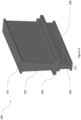
- Figure 1 shows a perspective view of a stator 100 designed to be operated with an outer rotor (not shown).
- the stator 100 includes a stator core 102.
- the stator core 102 extends in the axial direction z.
- the stator core 102 comprises stator teeth 112 arranged to project radially outwards from the outer circumference of the stator core 102 in the radial direction r.
- the teeth are spaced azimuthally from each other in the azimuthal direction ⁇ .
- the stator core extends circumferentially around a heat sink 104, and is arranged to be used with an outer rotor (not shown) arranged around its outer circumference.
- the stator core 102 is azimuthally and axially symmetric.
- the heat sink 104 further includes an electronics housing 106 mounted onto each of its end faces.
- the electronics housing 106 includes all electronics required to operate the motor (not shown), and protects the electronics from moisture, foreign object damage and corrosion.
- An axle 108 passes through the centre of each of the electronics housing 106, heat sink 104 and stator core 102, such that they are all coaxially mounted and wires are able to be passed through the interior of the stator core 102 via the axle 108.
- stator teeth 112 are surrounded by bundles of stator windings 110, which are wound around the stator teeth 112 and fill the gaps formed by the stator teeth (not shown).
- Figure 2a shows an end-on view of an individual first stator tooth 200.
- the first stator tooth 200 comprises a radially extending first body portion 202, with a distal end flange 210 (distal to the centre of the stator) extending substantially azimuthally.
- the first central flange comprises a first arm portion 204 comprising a flange extending azimuthally away from the first body portion 202.
- the first arm portion 204 is substantially 'L' shaped when viewed from an end face of the stator tooth.
- the first central flange further comprises a second arm portion 208 comprising a flange extending azimuthally away from the first body portion 202 in the opposite direction to the first arm portion 204.
- the second arm portion 208 is substantially reverse 'L' shaped when viewed from an end face of the stator tooth, such that the shape of the first and second arm portions 204, 208 are complementary.
- a second body portion 206 extends radially from the second arm portion 208, such that it is aligned with the radial extent of the first body portion 202.
- the width of the second body portion 206 is less than that of the first body portion 202.
- the length of the second body portion 206 is also substantially less than that of the first body portion 202.
- a proximal end flange 212 extending azimuthally from either side of the second body portion 206.
- first and second arm portions 204, 208 are arranged such that when a plurality of first stator teeth 200 are arranged side-by-side, the first arm portions 204 are able to engage with the second arm portions 208 of the adjacent stator tooth 200, as shown in Figure 3a .
- This forms a circle of stator teeth 200 and enables continuous stator core to be formed.
- the first body portion 202 is tapered, being wider at the end towards the distal end flange 210, and narrower at the end towards the first arm portion 204.
- the second body portion 206 is also tapered, being narrower at the end towards the proximal end flange 212.
- Figure 2b shows an alternative second stator tooth 201 with upper body portion 202, lower body portion 206, proximal end flange 212 and distal end flange 210.
- the second stator tooth 201 comprises a second central flange 214 extending azimuthally away from both sides of the first body portion 202.
- the second central flange 214 is the same shape on both sides of the second stator tooth 201.
- Figure 2c shows a perspective view of the first stator tooth 200 shown in Figure 2a .
- the first stator tooth 200 extends axially along the desired axial length of the stator core.
- the first stator tooth 200 may be formed from multiple laminations of the same cross-sectional shape (e.g. that shown in Figure 2a ), which are then joined together to form the axially elongated tooth 200 shown in Figure 2c .
- the second stator tooth 201 also extends axially along the desired axial length of the stator core (not shown), and may be formed from multiple laminations joined together in the same way as for the first stator tooth 200.
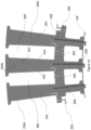
- Figure 3a shows a plurality of first stator teeth 200a, 200b, 200c (i.e. as shown in Figures 2a and 2c ) arranged side-by-side such that they are adjacent to each other surrounding the outer circumference of the heat sink 104.
- the tapered first body portion 202 is such that when the plurality of first stator teeth 200a, 200b, 200c are arranged side-by-side in a circle (i.e. around the outer circumference of the heat sink 104), there is a substantially uniform gap 300 between the first body portion 202 of the stator teeth 200a and 200b, and 200b and 200c respectively. Furthermore, the axially extending surfaces 302, 304 of the first stator teeth 200a, 200b, 200c are substantially parallel.
- the first stator teeth 200a, 200b, 200c are arranged such that the first arm portions 204 of each first stator tooth 200b, 200c engage with the respective second arm portions 208 of the adjacent first stator tooth 200a, 200b. This enables electromagnetic flux and heat to be transferred between the teeth via a first route 306.
- first stator teeth 200 are mounted on the heat sink 104, heat and electromagnetic flux are also transferred from each first stator tooth 200 to the heat sink 104 via a second route 308.
- Figure 3b shows a plurality of second stator teeth 201a, 201b, 201c (i.e. as shown in Figure 2b ) arranged side-by-side such that they are adjacent to each other surrounding the outer circumference of the heat sink 104.
- the second stator teeth 201a, 201b, 201c are arranged such that the second central flange 214 of each second stator tooth 201a, 201b, 201c engages with the respective second central flange 214 of the adjacent second stator tooth 201a, 201b, 201c.
- This enables electromagnetic flux and heat to be transferred between the teeth via a third route 310.
- heat and electromagnetic flux are also transferred from each second stator tooth 201 to the heat sink 104 via a fourth route 312.
- Figure 4 shows a perspective view of the first stator tooth 200 of Figures 2a and 2c , with stator windings 406 wrapped around the first body portion 202 of the first stator tooth 200.
- the azimuthal extent of the distal end flange 210 and the first arm portion 204 help to hold the stator windings in position.
- a winding guide 404 is positioned on each end face of the first body portion 202. This helps the stator windings 406 to be wound uniformly around the first stator tooth 200.
- the winding guide 404 also helps to electrically insulate the windings 406 from the first stator tooth 200.
- the sides of the tooth are also surrounded by a slot liner 402, to electrically insulate the windings 406 from the stator tooth 200.
- the second stator tooth 201 (shown in Figure 2b ) may also have stator windings and winding guides arranged in the same way (not shown).
- Figure 5a shows an enlarged cross-sectional view of the assembled stator core, formed from a plurality of first stator teeth 200 slotted together, and includes the stator windings 406 between the plurality of first body portions 202.
- the stator teeth 200 are arranged around the heat sink 104 such that heat is able to transfer from the stator tooth to the heat sink via the first cooling paths 506.
- the clamping element 502 is part of a clamping mechanism that helps to prevent azimuthal movement of each stator tooth 200, and extends along the axial length of each stator tooth 200. This is supported by the clamping rod 504, which extends substantially along the length of the axial length of each stator tooth 200.
- the distal end of the clamping rod 504 extends azimuthally (not shown in Figure 5 ), which helps to prevent the axial movement of the clamping rod 504 and hence the clamping element 502.
- each first stator tooth 200 As the second body portion 206 of each first stator tooth 200 is tapered, the surfaces between adjacent stator teeth are substantially parallel and hence the gaps between pairs of adjacent second body portions 206 are substantially equal, which helps to ease the positioning of the clamping elements 502 between the pairs of first stator teeth 200.
- This arrangement is also possible using a plurality of second stator teeth 201 of Figure 2b (not shown).
- each stator tooth may not be tapered, such that the surfaces between adjacent stator teeth are angled with respect to each other.
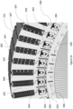
- Figure 5b shows an end-on view of the assembled stator core shown in Figure 5a , which shows the uniform air gaps 508 between the adjacent pairs of first stator teeth 200 and their associated windings 406.
- Figure 5b also shows the clamping elements 502 and the clamping rods 504, relative to the heat sink 104.
- Figure 6 shows an enlarged radial cross-section of the assembled stator core shown in Figure 5b .
- the clamping element 502 exerts forces 606 on the respective stator tooth 200.
- the clamping element 502 exerts a radially inward force onto the upper surface of the respective proximal end flanges 212, which holds the stator teeth 200 together.
- the clamping element 502 also exerts an azimuthal force onto the sides of the respective second body portions 206 of the adjacent stator teeth 200, further helping to maintain the relative positions of the clamping elements 502 and stator teeth 200.
- the azimuthal surfaces of the first and second arm portions 204, 208 are substantially in contact with each other when the stator teeth 200 are arranged adjacent to each other.
- the azimuthal surfaces of contact between the arm portions 204, 208 provide a path for heat transfer and electromagnetic flux transfer between neighbouring teeth.
- first and second arm portions 204, 208 are arranged to engage, there is a small gap 604 between the radial surfaces of the first and second arm portions 204, 208 (i.e. in the azimuthal direction). There is substantially no gap between the azimuthal surfaces of the first and second arm portions 204, 208 (i.e. in the radial direction) such that there is engagement 605 between adjacent pairs of stator teeth 200.
- This small gap 604 allows for larger manufacturing tolerances of the stator assembly.
- the small gap 604 allows for any small variations in the dimensions of each stator tooth 200 and clamping element 502 whilst still enabling the first and second arm portions 204, 208 to engage. This may help to reduce manufacturing costs. Furthermore, this helps to prevent damage to the stator teeth from excessive rubbing during assembly of the stator core as the small gap 604 absorbs the circular stackup of the adjacent stator teeth 200 and clamping elements 502.
- the small gap 604 enables a continuous stator core to be formed from the plurality of stator teeth 200 even at the extremes of the manufacturing tolerances.
- stator assembly By allowing for the small gap 604 between stator teeth 200, only the azimuthal surfaces of the first and second arm portions 204, 208 may need to be machined after the stator tooth 200 has been stamped. This machining helps to ensure alignment, and face-to-face contact between the stator teeth, and reduces surface roughness. As the radial surfaces of the first and second arm portions 204, 208 may not need to be machined, the manufacturing cost of the stator assembly may be reduced.
- each clamping mechanism includes the clamping element 502, the clamping rod 504, clamping cones 602 and a compression element 702.
- the clamping rod 504 further comprises an end piece 704 extending perpendicular to the axial extent of the clamping rod 504.
- Figure 8 shows an axial cross-section of the stator core, and shows the clamping mechanism in more detail.
- the clamping element 502 is inserted between the stator teeth 200, and extends along the axial length of the stator tooth.
- the clamping rod 504 is inserted from the end face of the stator core, and is substantially longer than the axial length of the clamping element 502.
- the clamping rod 504 radially extends from an end face of the stator core, and may be secured in place by the compression element 702, and a nut 802 at an end face of the stator core. At the end of the clamping rod 504 distal from the nut 802, the clamping rod 504 radially extends from an end face of the stator core, and includes an end piece extending substantially azimuthally. This end piece engages with the end face of the stator core, and helps to keep the clamping rod in position during assembly of the clamping mechanism.
- the end piece 704 has a substantially oval cross-section, however other shapes are also envisaged.
- the end piece 704 of the clamping rod 504 is shaped such that it is complementary to the end face of the heat sink (not shown), which allows each clamping mechanism to engage with the heat sink 104 to further secure the stator assembly. This also prevents azimuthal rotation of the clamping rod 504 when the respective nut 802 is tightened during assembly.
- the clamping rod 504 is surrounded by the pair of hollow clamping cones 602, which are slid onto the clamping rod 504 during assembly.
- a clamping cone 602 is arranged at each end of the clamping rod 504 and sits between the clamping rod 504 and the clamping element 502.
- the inner surface of the clamping element 502 is shaped complementary to the outer face of the clamping cone 602 such that the clamping element 502 engages with the pair of clamping cones 602.
- the clamping element 502 engages with the second body portions 206 and proximal end flanges 208 of the respective adjacent pair of stator teeth 200.
- the base of each clamping cone 602 is also in contact with the heat sink 104, such that there is a reaction force transmitted from the heat sink 104 through the clamping cone 602 to the clamping element 504 and hence the respective stator teeth 200.
- a torque force is exerted on the nut 802 when it is tightened, and this is transmitted though the compression element 702 as an axial force acting on one end of the clamping cone 602 proximal to the compression element 702.
- axially directed reaction forces on the distal end of the clamping rod 504 act on one end of the clamping cone 602 distal from the compression element 702.
- the compression and reaction forces are transferred through each of the clamping cones 602 as axial forces acting in opposite directions along the clamping element 502, helping to prevent axial movement of the clamping mechanism.
- the compression and reaction forces are also transmitted radially from the compression cones 602 to the clamping element 502, resulting in the radial forces 606 acting on the stator teeth as shown in Figure 6 . This helps to bring together the stator teeth 200 and clamp them in place.
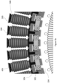
- Figure 9 shows an enlarged perspective view of the assembled stator.
- the clamping mechanism 502 is arranged coaxial to the clamping rod 504, where the end of the clamping rod 504 engages with the front face of the heat sink 104 such that the clamping mechanism 502 is attached to the heat sink 104.
- pairs of adjacent clamping mechanisms 502 are connected by a plate 902 mounted over the heat sink 104 to the pairs of respective clamping rods 504, wherein the plate 902 is secured by the nut 802.
- Each nut 802 is attached to the respective clamping rod 504 by threaded engagement (not shown). Therefore, each clamping mechanism and respective pairs adjacent stator teeth are clamped to the heat sink 104, and tightening the nut 802 further secures the clamping mechanism and hence respective adjacent pair of stator teeth 200 to the heat sink 104. This further helps to prevent axial and azimuthal movement of each of the stator teeth 200, as well as securing the position of the heat sink 104 relative to the stator teeth.
- the ends of the plate 902 may be bent such that they are in contact with one of the hexagonal faces of each nut 802. This secures the nuts 802 in place by preventing their unwanted rotation.
Landscapes
- Engineering & Computer Science (AREA)
- Power Engineering (AREA)
- Manufacturing & Machinery (AREA)
- Iron Core Of Rotating Electric Machines (AREA)
Priority Applications (2)
| Application Number | Priority Date | Filing Date | Title |
|---|---|---|---|
| EP23174386.5A EP4465486A1 (de) | 2023-05-19 | 2023-05-19 | Statoranordnung |
| US18/662,846 US20240388143A1 (en) | 2023-05-19 | 2024-05-13 | Stator assembly |
Applications Claiming Priority (1)
| Application Number | Priority Date | Filing Date | Title |
|---|---|---|---|
| EP23174386.5A EP4465486A1 (de) | 2023-05-19 | 2023-05-19 | Statoranordnung |
Publications (1)
| Publication Number | Publication Date |
|---|---|
| EP4465486A1 true EP4465486A1 (de) | 2024-11-20 |
Family
ID=86468907
Family Applications (1)
| Application Number | Title | Priority Date | Filing Date |
|---|---|---|---|
| EP23174386.5A Pending EP4465486A1 (de) | 2023-05-19 | 2023-05-19 | Statoranordnung |
Country Status (2)
| Country | Link |
|---|---|
| US (1) | US20240388143A1 (de) |
| EP (1) | EP4465486A1 (de) |
Citations (4)
| Publication number | Priority date | Publication date | Assignee | Title |
|---|---|---|---|---|
| CN103138422A (zh) * | 2011-11-22 | 2013-06-05 | 罗伯特·博世有限公司 | 具有分段的定子的电动机 |
| CN105515230A (zh) * | 2015-12-31 | 2016-04-20 | 北京金风科创风电设备有限公司 | 发电机的定子 |
| WO2021051702A1 (zh) * | 2019-09-17 | 2021-03-25 | 安徽皖南电机股份有限公司 | 电机内定子的紧固结构 |
| US20230038547A1 (en) * | 2021-08-09 | 2023-02-09 | Ebm-Papst Mulfingen Gmbh & Co. Kg | Stator for an electric motor |
Family Cites Families (3)
| Publication number | Priority date | Publication date | Assignee | Title |
|---|---|---|---|---|
| US8253298B2 (en) * | 2008-07-28 | 2012-08-28 | Direct Drive Systems, Inc. | Slot configuration of an electric machine |
| US8274192B2 (en) * | 2010-08-30 | 2012-09-25 | General Electric Company | Segmented stator assembly |
| US9071096B2 (en) * | 2011-11-09 | 2015-06-30 | Siemens Energy, Inc. | Clamping structure for a stator core |
-
2023
- 2023-05-19 EP EP23174386.5A patent/EP4465486A1/de active Pending
-
2024
- 2024-05-13 US US18/662,846 patent/US20240388143A1/en active Pending
Patent Citations (4)
| Publication number | Priority date | Publication date | Assignee | Title |
|---|---|---|---|---|
| CN103138422A (zh) * | 2011-11-22 | 2013-06-05 | 罗伯特·博世有限公司 | 具有分段的定子的电动机 |
| CN105515230A (zh) * | 2015-12-31 | 2016-04-20 | 北京金风科创风电设备有限公司 | 发电机的定子 |
| WO2021051702A1 (zh) * | 2019-09-17 | 2021-03-25 | 安徽皖南电机股份有限公司 | 电机内定子的紧固结构 |
| US20230038547A1 (en) * | 2021-08-09 | 2023-02-09 | Ebm-Papst Mulfingen Gmbh & Co. Kg | Stator for an electric motor |
Also Published As
| Publication number | Publication date |
|---|---|
| US20240388143A1 (en) | 2024-11-21 |
Similar Documents
| Publication | Publication Date | Title |
|---|---|---|
| US11923739B1 (en) | Electric motor with bar wound stator and end turn cooling | |
| US8154163B2 (en) | Electric power collection/distribution ring of rotary electric machine | |
| US10381890B2 (en) | Axial-gap rotating electric machine | |
| EP1292004B1 (de) | Elektrischer Motor mit zwei Rotoren und einem Stator | |
| US20220278579A1 (en) | Disc rotor machine for a motor vehicle drive | |
| US6661124B1 (en) | Linear motor coils assembly and method for manufacturing the same | |
| CN101151779B (zh) | 包括插置在轴和极片之间的中间套筒的旋转电动设备所用的转子以及制造该转子的方法 | |
| US20240322619A1 (en) | Stator for a radial flux double-rotor machine, radial flux double-rotor machine and method for producing a stator for a radial flux double-rotor machine | |
| US7567010B1 (en) | Modular electric motor with stackable stator poles | |
| US10177612B2 (en) | Motor with stator fixing structure | |
| US10951076B2 (en) | Electric machines | |
| CN110867993A (zh) | 电动马达的环形定子 | |
| US11205935B2 (en) | Axial gap dynamo-electric machine | |
| US20240162761A1 (en) | Stator for Dynamo-Electric Machine, Dynamo-Electric Machine, Electric Drive System, and Electrified Wheel | |
| KR20130131228A (ko) | 도체 스페이서 클립 | |
| CN101421908A (zh) | 包括在磁极的齿中加工槽的步骤的用于制造转子的方法及由所述方法获得的转子 | |
| JPH0771389B2 (ja) | ダイナモ電気機械の固定子支持配列構成 | |
| US20030062795A1 (en) | Motor, motor stator and method for manufacturing the same | |
| EP4465486A1 (de) | Statoranordnung | |
| JP6552718B2 (ja) | 回転電機の固定子、回転電機、及び回転電機の固定子の製造方法 | |
| US20250373091A1 (en) | Stator for an Electric Axial Flux Machine, Method for Producing Such a Stator, and Electric Axial Flux Machine Having Such a Stator | |
| CN111130282B (zh) | 制造定子的方法 | |
| KR20220047858A (ko) | 원환형 권선을 가지는 장치 | |
| US6876120B2 (en) | Inner core structure of a rotary transformer-type resolver | |
| CN119422307A (zh) | 用于电机的转子、方法以及组装装置 |
Legal Events
| Date | Code | Title | Description |
|---|---|---|---|
| PUAI | Public reference made under article 153(3) epc to a published international application that has entered the european phase |
Free format text: ORIGINAL CODE: 0009012 |
|
| STAA | Information on the status of an ep patent application or granted ep patent |
Free format text: STATUS: THE APPLICATION HAS BEEN PUBLISHED |
|
| AK | Designated contracting states |
Kind code of ref document: A1 Designated state(s): AL AT BE BG CH CY CZ DE DK EE ES FI FR GB GR HR HU IE IS IT LI LT LU LV MC ME MK MT NL NO PL PT RO RS SE SI SK SM TR |
|
| STAA | Information on the status of an ep patent application or granted ep patent |
Free format text: STATUS: REQUEST FOR EXAMINATION WAS MADE |
|
| 17P | Request for examination filed |
Effective date: 20250110 |
|
| STAA | Information on the status of an ep patent application or granted ep patent |
Free format text: STATUS: EXAMINATION IS IN PROGRESS |
|
| 17Q | First examination report despatched |
Effective date: 20250409 |