EP4465481A1 - Selbststromerzeugungsschalter, verarbeitungsverfahren dafür und verarbeitungssystem - Google Patents
Selbststromerzeugungsschalter, verarbeitungsverfahren dafür und verarbeitungssystem Download PDFInfo
- Publication number
- EP4465481A1 EP4465481A1 EP23737157.0A EP23737157A EP4465481A1 EP 4465481 A1 EP4465481 A1 EP 4465481A1 EP 23737157 A EP23737157 A EP 23737157A EP 4465481 A1 EP4465481 A1 EP 4465481A1
- Authority
- EP
- European Patent Office
- Prior art keywords
- module
- self
- electrical energy
- communication processing
- power generating
- Prior art date
- Legal status (The legal status is an assumption and is not a legal conclusion. Google has not performed a legal analysis and makes no representation as to the accuracy of the status listed.)
- Pending
Links
Images


Classifications
-
- H—ELECTRICITY
- H02—GENERATION; CONVERSION OR DISTRIBUTION OF ELECTRIC POWER
- H02J—ELECTRIC POWER NETWORKS; CIRCUIT ARRANGEMENTS OR SYSTEMS FOR SUPPLYING OR DISTRIBUTING ELECTRIC POWER; SYSTEMS FOR STORING ELECTRIC ENERGY
- H02J7/00—Circuit arrangements for charging or discharging batteries or for supplying loads from batteries
- H02J7/32—Circuit arrangements for charging or discharging batteries or for supplying loads from batteries for charging batteries from a charging set comprising a non-electric prime mover rotating at constant speed
-
- H—ELECTRICITY
- H01—ELECTRIC ELEMENTS
- H01H—ELECTRIC SWITCHES; RELAYS; SELECTORS; EMERGENCY PROTECTIVE DEVICES
- H01H13/00—Switches having rectilinearly-movable operating part or parts adapted for pushing or pulling in one direction only, e.g. push-button switch
- H01H13/02—Details
-
- H—ELECTRICITY
- H01—ELECTRIC ELEMENTS
- H01H—ELECTRIC SWITCHES; RELAYS; SELECTORS; EMERGENCY PROTECTIVE DEVICES
- H01H13/00—Switches having rectilinearly-movable operating part or parts adapted for pushing or pulling in one direction only, e.g. push-button switch
- H01H13/02—Details
- H01H13/12—Movable parts; Contacts mounted thereon
- H01H13/14—Operating parts, e.g. push-button
-
- H—ELECTRICITY
- H02—GENERATION; CONVERSION OR DISTRIBUTION OF ELECTRIC POWER
- H02J—ELECTRIC POWER NETWORKS; CIRCUIT ARRANGEMENTS OR SYSTEMS FOR SUPPLYING OR DISTRIBUTING ELECTRIC POWER; SYSTEMS FOR STORING ELECTRIC ENERGY
- H02J13/00—Circuit arrangements for providing remote monitoring or remote control of equipment in a power distribution network
- H02J13/13—Circuit arrangements for providing remote monitoring or remote control of equipment in a power distribution network characterised by the transmission of data to equipment in the power network
- H02J13/1331—Circuit arrangements for providing remote monitoring or remote control of equipment in a power distribution network characterised by the transmission of data to equipment in the power network using wireless data transmission
- H02J13/1333—Circuit arrangements for providing remote monitoring or remote control of equipment in a power distribution network characterised by the transmission of data to equipment in the power network using wireless data transmission by means of mobile telephony
-
- H—ELECTRICITY
- H02—GENERATION; CONVERSION OR DISTRIBUTION OF ELECTRIC POWER
- H02J—ELECTRIC POWER NETWORKS; CIRCUIT ARRANGEMENTS OR SYSTEMS FOR SUPPLYING OR DISTRIBUTING ELECTRIC POWER; SYSTEMS FOR STORING ELECTRIC ENERGY
- H02J13/00—Circuit arrangements for providing remote monitoring or remote control of equipment in a power distribution network
- H02J13/13—Circuit arrangements for providing remote monitoring or remote control of equipment in a power distribution network characterised by the transmission of data to equipment in the power network
- H02J13/1331—Circuit arrangements for providing remote monitoring or remote control of equipment in a power distribution network characterised by the transmission of data to equipment in the power network using wireless data transmission
- H02J13/1335—Circuit arrangements for providing remote monitoring or remote control of equipment in a power distribution network characterised by the transmission of data to equipment in the power network using wireless data transmission involving a local wireless network, e.g. Wi-Fi®, ZigBee® or Bluetooth®
-
- H—ELECTRICITY
- H02—GENERATION; CONVERSION OR DISTRIBUTION OF ELECTRIC POWER
- H02K—DYNAMO-ELECTRIC MACHINES
- H02K35/00—Generators with reciprocating, oscillating or vibrating coil system, magnet, armature or other part of the magnetic circuit
- H02K35/02—Generators with reciprocating, oscillating or vibrating coil system, magnet, armature or other part of the magnetic circuit with moving magnets and stationary coil systems
-
- H—ELECTRICITY
- H02—GENERATION; CONVERSION OR DISTRIBUTION OF ELECTRIC POWER
- H02N—ELECTRIC MACHINES NOT OTHERWISE PROVIDED FOR
- H02N11/00—Generators or motors not provided for elsewhere; Alleged perpetua mobilia obtained by electric or magnetic means
- H02N11/002—Generators
-
- H—ELECTRICITY
- H01—ELECTRIC ELEMENTS
- H01H—ELECTRIC SWITCHES; RELAYS; SELECTORS; EMERGENCY PROTECTIVE DEVICES
- H01H2239/00—Miscellaneous
- H01H2239/076—Key stroke generating power
-
- H—ELECTRICITY
- H02—GENERATION; CONVERSION OR DISTRIBUTION OF ELECTRIC POWER
- H02J—ELECTRIC POWER NETWORKS; CIRCUIT ARRANGEMENTS OR SYSTEMS FOR SUPPLYING OR DISTRIBUTING ELECTRIC POWER; SYSTEMS FOR STORING ELECTRIC ENERGY
- H02J2105/00—Networks for supplying or distributing electric power characterised by their spatial reach or by the load
- H02J2105/10—Local stationary networks having a local or delimited stationary reach
- H02J2105/12—Local stationary networks having a local or delimited stationary reach supplying households or buildings
-
- H—ELECTRICITY
- H03—ELECTRONIC CIRCUITRY
- H03K—PULSE TECHNIQUE
- H03K17/00—Electronic switching or gating, i.e. not by contact-making and –breaking
- H03K17/94—Electronic switching or gating, i.e. not by contact-making and –breaking characterised by the way in which the control signals are generated
- H03K17/965—Switches controlled by moving an element forming part of the switch
- H03K17/97—Switches controlled by moving an element forming part of the switch using a magnetic movable element
- H03K2017/9706—Inductive element
-
- H—ELECTRICITY
- H03—ELECTRONIC CIRCUITRY
- H03K—PULSE TECHNIQUE
- H03K2217/00—Indexing scheme related to electronic switching or gating, i.e. not by contact-making or -breaking covered by H03K17/00
- H03K2217/94—Indexing scheme related to electronic switching or gating, i.e. not by contact-making or -breaking covered by H03K17/00 characterised by the way in which the control signal is generated
- H03K2217/94084—Transmission of parameters among sensors or between sensor and remote station
- H03K2217/94089—Wireless transmission
Definitions
- the present invention relates to the field of self-power generating switches, in particular to a self-power generating switch, a processing method therefor, and a processing system.
- a self-power generating switch can be understood as a switch configured with a power generator, and electrical energy required by a circuit in the switch can be supplied by electrical energy generated by the power generator.
- a communication processing module can also be configured in the self-power generating switch, and then, the communication processing module is utilized for communication with the outside of the self-power generating switch.
- a network distribution process of the self-power generating switch can only be achieved by means of electrical energy generated by self-power generation of the self-power generating switch.
- the electrical energy generated by the self-power generation is limited, which greatly limits the volume of data transmitted and processed in the network distribution process, and will not be beneficial to the achievement of network distribution.
- the present invention provides a self-power generating switch, a processing method therefor, and a processing system to solve the problem that electrical energy generated by self-power generation is limited.
- a self-power generating switch including:
- the self-power generating switch includes: at least one key, a power generator, and a switch circuit;
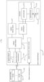
- the switch circuit includes a communication processing module, an energy storage module, a rectification module, a voltage output module, a storage module, and an electrical energy receiving module;
- the power generator includes an induction part and a movement part;
- the communication processing module is electrically connected to the storage module, the induction part is electrically connected to the energy storage module through the rectification module, and the energy storage module is electrically connected to the communication processing module and the storage module through the voltage output module;
- the key is directly or indirectly driven by the movement part; and the electrical energy receiving module is directly or indirectly electrically connected to the voltage output module;
- the processing method includes:
- a processing system based on a switch, including the self-power generating switch in the first aspect, or the self-power generating switch for performing the processing method in the second aspect, and the target network.
- the electrical energy receiving module is further used to receive the electrical energy from the outside of the self-power generating switch; at the same time, for the electrical energy received from the outside of the self-power generating switch and the electrical energy generated by the self-power generation, network distribution is achieved by means of the electrical energy received from the outside of the self-power generating switch, and then, the volume of data transmitted and processed in a network distribution process is no longer limited by the self-generated electrical energy; and the present invention is beneficial to the achievement of a more complicated network distribution process.
- first and second are only for a purpose of description, and cannot be understood as indicating or implying the relative importance or implicitly indicating the number of indicated technical features. Therefore, the features defined as “first” and “second” may explicitly or implicitly include one or more of the features.
- a plurality of' means more, such as two, three, and four, unless it may be specifically defined otherwise.
- connection should be understood in a broad sense unless otherwise specified and defined, for example, it may be fixed connection or detachable connection or an integral whole, may be mechanical connection or electrical connection or mutual communication, may be direct connection or indirect connection through an intermediate medium, and may be internal connection of two elements or interaction between two elements.
- connection should be understood in a broad sense unless otherwise specified and defined, for example, it may be fixed connection or detachable connection or an integral whole, may be mechanical connection or electrical connection or mutual communication, may be direct connection or indirect connection through an intermediate medium, and may be internal connection of two elements or interaction between two elements.
- embodiments of the present invention provide a processing system based on a switch, and also provide a self-power generating switch 100 and a processing method therefor, wherein the processing system includes the self-power generating switch 100.
- a target network 200 can also be included, and the target network 200 can be a Zigbee network or a Bluetooth network.
- a gateway 202 can be any apparatus capable of forming and/or managing the corresponding target network 200 or any combination of the apparatuses, and there can be one o more gateways 202, which is not limited thereto.
- the gateway 202 is a gateway device or a sound box with a gateway function.
- Devices 201 in the target network 200 can include, for example, at least one of an intelligent wall switch, an intelligent curtain, and an intelligent lamp. These devices 201 can be controlled by a control message sent by the self-power generating switch to perform corresponding actions.
- the processing system can further include a mobile terminal 300 which can achieve communication with the self-power generating switch and the device and/or gateway in the target network, wherein the communication can be direct or indirect.
- the mobile terminal 300 can be a mobile phone, a tablet personal computer, a computer, etc.
- the mobile terminal 300 can also acquire the control message of the self-power generating switch, thereby being controlled or achieving the forwarding of the control message, or achieving control based on the control message.
- the specified device in the target network is further configured to:
- a network distribution process of the self-power generating switch can depend on the mobile terminal 300, and then, the mobile terminal is configured to send safety information (such as a network access password) of the target network to the self-power generating switch when performing the network distribution.
- safety information such as a network access password
- a network distribution process of the gateway can depend on the mobile terminal 300, and then, the mobile terminal is further configured to send the safety information (such as a network access password) to the gateway, so that the gateway is added into the target network.
- the self-power generating switch 100 provided in an embodiment of the present invention includes:
- the power generator 103 includes an induction part 1032 and a movement part 1031;
- the movement part 1031 can be understood as one or a combination of parts which can be driven by at least one of the key, a reset component, etc. to move;
- the induction part 1032 can be understood as one or a combination of parts which can interact with the movement part 1031 to generate electrical energy by induction when the movement part moves; and any structure capable of generating electrical energy based on movement in the art can be used as an optional solution of the embodiment of the present invention.
- a permanent magnet part, a magnetic conduction part and a coil part can be configured in the power generator 103, the coil part can be disposed on the magnetic conduction part, and then, when the permanent magnet part moves relative to the magnetic conduction part, the coil part can generate an induction voltage.
- the coil part can be regarded as above-mentioned induction part 1032, and the permanent magnet part or magnetic conduction part can be regarded as above-mentioned movement part 1031, that is, in parts of examples, the permanent magnet part moves, thereby being directly or indirectly driven together with the key, the reset component, etc.; and in other parts of examples, the magnetic conduction part moves, thereby being directly or indirectly driven together with the key, the reset component, etc.
- the induction part 1032 may move with the movement part 1031, or not move with the movement part 1031.
- the communication processing module 102 is electrically connected to the storage module 108, the induction part 1032 is electrically connected to the energy storage module 105 through the rectification module 104, and the energy storage module 105 is electrically connected to the communication processing module 102 and the storage module 108 through the voltage output module 106;
- the key is directly or indirectly driven by the movement part; wherein the movement part is configured to be driven to move in a first direction when the key is pressed downwardly;
- the induction part is arranged to generate a first induction voltage in response to the movement of the movement part in the first direction;
- the rectification module is arranged to rectify first electrical energy corresponding to the first induction voltage and then storing the rectified electrical energy in the energy storage module; and the energy storage module is arranged to transmit the stored electrical energy to the voltage output module.
- the electrical energy receiving module 107 is directly or indirectly electrically connected to the voltage output module 106; and the electrical energy receiving module 107 is configured to: when receiving external electrical energy transmitted from the outside of the self-power generating switch 100, transmit the external electrical energy to the voltage output module;
- the voltage output module 106 can, for example, perform voltage conversion (such as voltage reduction and/or voltage stabilization) on the received electrical energy, and then, transmit the converted voltage to the communication processing module 102 and the storage module 108 to supply power to the same, so that they are powered on.
- voltage conversion such as voltage reduction and/or voltage stabilization
- the self-power generating switch 1 further includes a reset component 109.
- the reset component 109 is configured to be directly or indirectly driven by the movement part 1031 of the power generator 103, the reset component 109 is configured to deform in response to the movement of the movement part 1031 in the first direction and generating a reset action force overcoming the deformation, and the reset component 109 is further configured to drive the movement part 1031 to move in a second direction and the key to rebound by means of the reset action force after an action force for downwardly pressing of the key is removed; a second induction voltage can be generated when the movement part moves in the second direction; and the rectification module 104 can be further configured to store second electrical energy corresponding to the second induction voltage into the energy storage module.
- the storage module 108 can be configured to store current channel information. Specifically, the current channel information can be stored in the storage module 108 based on any processing process and interaction way.
- the storage module 108 can be a memory in which data is not lost after being powered down.
- the storage module 108 can also be configured to only work after being powered on and be powered down after work. Therefore, due to above configuration for the storage module, the storage module 108 can ensure the storage and maintenance of above information and guarantee the accuracy of the information.
- the self-power generating switch 1 can further include a memory integrated into the communication processing module 102, and the memory can store, for example, codes required by the processing of the communication processing module 102.
- the storage module 108 can be integrated into the communication processing module 102 or independent of the communication processing module 102.
- the electrical energy receiving module is further used to receive the electrical energy from the outside of the self-power generating switch 100; at the same time, for the electrical energy received from the outside of the self-power generating switch 100and the electrical energy generated by the self-power generation, network distribution is achieved by means of the electrical energy received from the outside of the self-power generating switch 100, and then, the volume of data transmitted and processed in a network distribution process is no longer limited by the self-generated electrical energy; and the present invention is beneficial to the achievement of a more complicated network distribution process.
- the communication processing module 102 before performing network distribution of the self-power generating switch and a target network, is further configured to: determine that the self-power generating switch is in a network undistributed state and/or determine that the self-power generating switch is in a network distributed state, but is detected to find a reset operation.
- the reset operation is configured to indicate the communication processing module to reperform the network distribution.
- the reset operation can be, for example, an operation of a user for a reset button (or the key 101), which can be pressing once or more times (such as three times and five times) or long pressing.
- network distribution is only performed when network distribution is not performed, or the external electrical energy is received, or network distribution is performed, but reset is needed, which avoids the unnecessary performing of a network distribution process, is beneficial to the reduction of energy consumption, and meets a network distribution demand of the user.
- the communication processing module when performing network distribution of the self-power generating switch and a target network, is specifically configured to: send a network distribution message to the outside of the self-power generating switch 100, so that a mobile terminal acquiring the network distribution message feeds safety information (such as the network access password) of the target network back to the self-power generating switch; and then, store the safety information (such as the network access password) into the storage module.
- safety information such as the network access password
- the target network is an example of the Bluetooth network.
- the communication processing module 102 is further configured to:
- the communication processing module is specifically configured to:
- the determination of the target channel is achieved, for example, it can be applied to a situation when the target network is the Zigbee network.
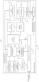
- the self-power generating switch 100 can further includes an external electrical energy detection module 120.
- the external electrical energy detection module 120 is electrically connected to the electrical energy receiving module 107 and the communication processing module 102; for example, it can be electrically connected to an output side and/or input side of the electrical energy receiving module 107, and can be electrically connected to a signal interaction end of the communication processing module 102.
- the external electrical energy detection module 120 is configured to: detect whether the electrical energy receiving module receives the external electrical energy, and feed a corresponding detection result back to the communication processing module 102.
- the corresponding detection result is a first detection result or a second detection result
- the first detection result represents that the electrical energy receiving module receives the external electrical energy
- the second detection result represents that the electrical energy receiving module does not receive the external electrical energy
- the feedback of the detection result can be achieved by signals with different voltages (or levels) by means of a simulation quantity, and in other examples, the feedback of the detection result can also be achieved by digital signals.
- the communication processing module 102 is further configured to: determine that the corresponding detection result is the first detection result.
- the communication processing module 102 can perform network distribution only in the case that it is detected that there is the external electrical energy, which ensures that there is sufficient, continuous and stable electrical energy supply during network distribution.
- the external electrical energy detection module 120 includes a first voltage division resistor R1, a second voltage division resistor R2, and a detection feedback capacitor C1.
- a first end of the first voltage division resistor R1 is electrically connected to the electrical energy receiving module 107, a second end of the first voltage division resistor R1 is electrically connected to a first end of the second voltage division resistor R2, a second end of the second voltage division resistor R2 is grounded, a first end of the detection feedback capacitor C1 is electrically connected to the second end of the first voltage division resistor R1, and a second end of the first voltage division resistor R1 is electrically connected to the communication processing module 102.
- the divided voltage fed back to the communication processing module can have a certain voltage value or can be a voltage within a certain voltage range, and the voltage cannot be generated in the case that no external power is supplied.
- the purpose of voltage division is to prevent the communication processing module and the storage module from burning out due to an overhigh voltage.
- the second voltage division resistor R2 can release the electrical energy in the detection feedback capacitor C1 to ensure that a processing apparatus can detect a low level.
- a comparator in order to further distinguish the external electrical energy from accidentally accessed electrical energy, can also be disposed between the first end of the detection feedback capacitor C1 and the communication processing module, thereby meeting a feedback demand.
- a power supply diode D1 is further provided between the electrical energy receiving module 107 and the voltage output module 106, and an anode of the power supply diode D1 is connected to the electrical energy receiving module 107.
- the electrical energy receiving module 107 includes a power supply interface 1071 which can be, for example, a USB interface.
- the electrical energy receiving module includes a power supply interface which is a power supply female having a width of smaller than or equal to 7.8 mm and a height of smaller than or equal to 4.1 mm.
- the electrical energy of the communication processing module is provided through the power supply interface, and thus, after detecting the external electrical energy, the external electrical energy detection module will output a high-level signal to the communication processing module; and if the electrical energy of the communication processing module is supplied by the power generator, the external electrical energy detection module will output a low-level signal to the communication processing module.
- a user firstly supplies power to the self-power generating switch by means of a data line (such as a USB line) through the power supply interface, and the electrical energy obtained by the power supply interface can be outputted to the communication processing module after being subjected to voltage reduction and voltage stabilization through the communication processing module 102. After the electrical energy obtained by the communication processing module is started, if it is detected that the external electrical energy detection module outputs a high level, it is regarded that the current power is supplied by the power supply interface, at the moment, a network distribution operation can be performed.
- the power supply interface is stable in power supply voltage and sufficient in power
- a plurality of (such as sixteen) zigbee channels can be automatically polled to find a channel of the zigbee network, then, the network distribution message is sent, after the network distribution is successful, an LED indication that network distribution is successful is outputted, for example, a corresponding indication is outputted outwards through an LED module.
- network distribution can be completed by inserting the data line in the self-power generating switch to wait for the LED module to emit light, and after network distribution is completed, the data line is pulled up, which is simple and convenient to operate.
- the self-power generating switch After the self-power generating switch is successful in network distribution, it is only necessary to send a simple zigbee control message, at the moment, the electrical energy receiving module no longer works, and power can be supplied by self-power generation.
- electrical energy generated by an action of the power generator is outputted as stable electrical energy by the voltage output module after being processed, such as rectification and energy storage, and the voltage output module can achieve functions, such as voltage reduction and voltage stabilization, and adjust the voltage to a voltage required by the communication processing module, etc.
- the communication processing module After the communication processing module is started, it is detected that the external electrical energy detection module outputs a low level, and therefore, the electrical energy is supplied by the power generator; and according to information (such as a key value) read by a key recognition module and an action recognition module, the key value can be combined to form the control message to be sent through a zigbee protocol.
- information such as a key value
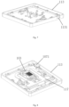
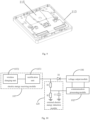
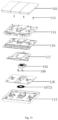
- the self-power generating switch further includes a bottom shell 113, a waterproof set 116, and a circuit board 118; the waterproof set 116 is disposed on the bottom shell 113 so that a waterproof space is formed between a bottom surface of the bottom shell and the waterproof set, the switch circuit is disposed on the circuit board 118, the circuit board 118 is disposed on the bottom shell 113, and the switch circuit is disposed in the waterproof space.
- the power supply interface 1071 is disposed on the bottom shell 113 and is electrically connected to the voltage output module through the circuit board 118, and the power supply interface 1071 is located outside the waterproof set.
- the bottom shell 113 can be provided with a connecting hole 1131, and the power supply interface 1071 can be disposed in the connecting hole 1131.
- the power supply interface 1071 is disposed outside a waterproof area, and thus, a waterproof function is mainly to protect electronic components except for the power supply interface and the power generator. In this way, it is beneficial to the reduction of the cost (a waterproof USB is expensive) and the simplification of design.
- the power supply interface can be located under (on a middle shell) the key or a side of the switch, in this way, no charging interface can be seen, which improves the sense of beauty.
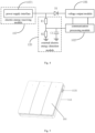
- the electrical energy receiving module 107 includes a wireless charging unit 1072, and the external electrical energy is acquired wirelessly.
- the wireless charging unit 1072 can include a wireless charging coil.
- the wireless charging unit can be used as a data exchange medium in addition to achieving charging.
- the electrical energy receiving module 107 can further include a rectification unit 1073 which is connected to the wireless charging unit 1072 and the voltage output module 106, and then, can rectify the electrical energy acquired by the wireless charging unit and transmit the rectified electrical energy to the voltage output module 106.
- a rectification unit 1073 which is connected to the wireless charging unit 1072 and the voltage output module 106, and then, can rectify the electrical energy acquired by the wireless charging unit and transmit the rectified electrical energy to the voltage output module 106.
- the wireless charging unit 1072 when a user requires network distribution, a self-power generating switch device is put on a wireless charging stand, and network distribution is successful after the LED module (such as an LED lamp) is lighted.
- a zigbee network device can be controlled by leaving the self-power generating switch from the wireless charging stand and pressing the switch.
- the bottom shell 113, the circuit board 118, the waterproof set 116, etc. mentioned as above can also be adopted.
- the self-generating switch 100 can further include a driving component 117, a middle shell 115 and a light guide component 114 no matter whether the wireless charging unit or the power supply interface is adopted, driving between the key 101 and the power generator 103 can be achieved by the driving component, the middle shell 115 can cover an upper side of the waterproof set 116, the key 101 can be movably connected to the middle shell 115 or the bottom shell 113, and the light guide component 114 can pass through the middle shell 115, the key 101 and the middle shell 115 and extends to the LED module on the circuit board 118, thereby achieving light guide to the outside of the self-power generating switch 100.
- the communication processing module when generating a control message, is specifically configured to: acquire current control information; the current control information representing control currently received by the self-power generating switch; and write the current control information into the control message.
- the current control information can be understood as the key value mentioned as above.
- the communication processing module is further configured to:
- the current control information includes current key information representing that a controlled key is received currently; refer to Fig. 3 , the self-power generating switch 100 further includes a key recognition module 110 for detecting the current key information, and the key recognition module 110 is electrically connected to the communication processing module.
- the key recognition module 110 includes at least one detection unit 1101, a detection switch is directly or indirectly driven by the corresponding key, and the detection unit is electrically connected to the communication processing module; and the detection unit is configured to feed a switch signal back to the communication processing module when an action of downwardly pressing of the corresponding key occurs, so that the communication processing module is arranged to determine the current key information based on the switch signal.
- the detection unit includes a microswitch directly or indirectly driven by the corresponding key and electrically connected to the communication processing module; the detection switch is configured to be touched by the corresponding key when the action of downwardly pressing of the corresponding key occurs, and feed the switch signal back to the communication processing module after the detection switch is touched.
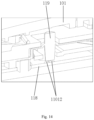
- the self-power generating switch further includes a silica gel column 119;
- the detection unit 1101 includes a first conductive part 11011 and a second conductive part 11012 disposed on the circuit board 118, the first conductive part 11011 is disposed on a tail end, facing the circuit board 118, of the silica gel column 119, and the second conductive part 11012 is electrically connected to the communication processing module.
- the silica gel column 119 is driven by the key 101 and is configured to be touched by the corresponding key to move to the circuit board when the action of downwardly pressing of the corresponding key occurs;
- the first conductive part can include, for example, conductive particles and/or conductive ink.
- the first conductive part is suitable for being disposed in a silica gel material and achieving conduction.
- the second conductive part 11012 includes a first connective subpart and a second conductive subpart (i.e., two second conductive parts 11012) separated in Fig. 14 ) which are both electrically connected to the communication processing module; and when the first conductive part is conducted to be in contact with the second conductive part, the first conductive part is conducted and connected between the first conductive subpart and the second conductive subpart.
- the silica gel column 119 can be disposed in the waterproof set 116, and in the case that the waterproof set 116 is made of a silica gel material, the silica gel column 119 and the waterproof set 116 can be integrated.
- the current control information includes current action information representing whether the current received control is an action of downwardly pressing of the key or an action of rebounding the key
- the self-power generating switch further includes an action recognition module 111 for recognizing the current action information
- the action recognition module 111 is electrically connected to the power generator 103 and the communication processing module 102.
- the reset component 109 is configured to be directly or indirectly driven by the movement part of the power generator, the reset component is arranged to deform in response to the movement of the movement part in the first direction and generating a reset action force overcoming the deformation, and the reset component is further arranged to drive the movement part to move in a second direction and the key to rebound by means of the reset action force after an action force for downwardly pressing of the key is removed.
- the induction part is arranged to generate a second induction voltage when the movement part moves in the second direction; and the rectification module is further configured to store second electrical energy corresponding to the second induction voltage into the energy storage module.
- the self-power generating switch achieves long-time power supply by the power supply interface or other ways. After poweron, if the self-power generating switch is in the network undistributed state, discoverable and linkable beacons are continuously sent through Blueteeth.
- a scanning mode of the mobile terminal (such as a mobile phone app) is started, after the self-power generating switch is scanned, a process of exchanging the key with the self-power generating switch is completed, the key (i.e., the safety information which can be, for example, specifically the network access password) will be stored by a semi-self-power generation Bluetooth wireless switch, and thus, the access of a device to a network can be achieved.
- the key i.e., the safety information which can be, for example, specifically the network access password
- the mobile terminal (such as the mobile phone app) can scan a gateway (such as the intelligent sound box or gateway device) and complete the access of the gateway (such as intelligent sound box or gateway device) to a network.
- a gateway such as an intelligent sound box or gateway device
- the mobile terminal can scan a gateway (such as the intelligent sound box or gateway device) and complete the access of the gateway (such as intelligent sound box or gateway device) to a network.
- the self-power generating switch and the gateway (such as an intelligent sound box or gateway device) belong to the same network secret key, power supplied to the self-power generating switch is removed to make the self-power generating switch enter a self-power generation state, generation is achieved by pressing the self-power generating switch, the self-power generating switch can send a series of beacon events (until the power is used up) by means of the energy, the gateway (such as the intelligent sound box or gateway device) is always in a Bluetooth broadcast monitoring state, and thus, the gateway (such as the intelligent sound box or gateway device) can receive the beacon events of the self-power generating switch.
- the gateway such as the intelligent sound box or gateway device
- the gateway After receiving the beacon events of the self-power generating switch, the gateway (such as the intelligent sound box or gateway device) can report the events to the IOT cloud.
- the mobile terminal (such as the mobile phone app) can acquire, from the IOT cloud, an event that the self-power generating switch is pressed down.
- a starting process of the self-power generating switch can be that, for example: after the power supplied to the self-power generating switch is removed, pressing generation is adopted, firstly, it is determined whether network distribution has been performed, if network distribution has been performed, the network secret key (such as the safety information which can be, for example, specifically the network access password) and a serial number of a message (since a Bluetooth message will be sent in a plurality of packets once, the serial number is used for deduplication) are read from a memory, the serial number is increased by 1, which represents a new message, and the updated serial number is stored. An effective load of the message is encrypted according to the network secret key and the serial number, and after the encryption is completed, a Bluetooth beacon message is continuously sent until the power is used up.
- the network secret key such as the safety information which can be, for example, specifically the network access password
- a serial number of a message since a Bluetooth message will be sent in a plurality of packets once, the serial number is used for deduplication
- an embodiment of the present invention further provides a processing method for the self-power generating switch, including:
- the processing method further includes: the communication processing module determines that the self-power generating switch is in a network undistributed state.
- the processing method further includes: the communication processing module determines that the self-power generating switch is in a network distributed state, but is detected to find a reset operation, the reset operation being configured to indicate the communication processing module to reperform the network distribution.
- the step that the communication processing module performs network distribution of the self-power generating switch and a target network specifically includes:
- the self-power generating switch further includes an external electrical energy detection module; the external electrical energy detection module is electrically connected to the electrical energy receiving module and the communication processing module; the processing method further includes:
- processing method further includes:
- the step that the communication processing module performs network distribution of the self-power generating switch and a target network specifically includes:
- the processing method further includes: if the response signal of the channel seeking message is not received, the communication processing module switches a channel, and takes the switched channel as a new current channel, so that the channel seeking message is sent through the new current channel.
- the step that the communication processing module generates a control message specifically includes:
- the step that the communication processing module generates a control message further includes:
- the self-power generating switch further includes a reset component
Landscapes
- Engineering & Computer Science (AREA)
- Power Engineering (AREA)
- Remote Monitoring And Control Of Power-Distribution Networks (AREA)
- Power Sources (AREA)
Applications Claiming Priority (2)
| Application Number | Priority Date | Filing Date | Title |
|---|---|---|---|
| CN202210023759.6A CN115276196A (zh) | 2022-01-10 | 2022-01-10 | 自发电开关及其处理方法、处理系统 |
| PCT/CN2023/071000 WO2023131295A1 (zh) | 2022-01-10 | 2023-01-06 | 自发电开关及其处理方法、处理系统 |
Publications (2)
| Publication Number | Publication Date |
|---|---|
| EP4465481A1 true EP4465481A1 (de) | 2024-11-20 |
| EP4465481A4 EP4465481A4 (de) | 2025-11-12 |
Family
ID=83758523
Family Applications (1)
| Application Number | Title | Priority Date | Filing Date |
|---|---|---|---|
| EP23737157.0A Pending EP4465481A4 (de) | 2022-01-10 | 2023-01-06 | Selbststromerzeugungsschalter, verarbeitungsverfahren dafür und verarbeitungssystem |
Country Status (4)
| Country | Link |
|---|---|
| US (1) | US20240356464A1 (de) |
| EP (1) | EP4465481A4 (de) |
| CN (1) | CN115276196A (de) |
| WO (1) | WO2023131295A1 (de) |
Families Citing this family (3)
| Publication number | Priority date | Publication date | Assignee | Title |
|---|---|---|---|---|
| CN115410846A (zh) * | 2021-05-16 | 2022-11-29 | 武汉领普科技有限公司 | 开关控制方法、自发电开关与接收端 |
| CN114008889B (zh) * | 2021-06-18 | 2024-09-20 | 武汉领普科技有限公司 | 供电电路、传感设备及其应用 |
| CN115276196A (zh) * | 2022-01-10 | 2022-11-01 | 武汉领普科技有限公司 | 自发电开关及其处理方法、处理系统 |
Family Cites Families (11)
| Publication number | Priority date | Publication date | Assignee | Title |
|---|---|---|---|---|
| CN106887894A (zh) * | 2017-03-22 | 2017-06-23 | 深圳市鹏星光电科技有限公司 | 一种无线传感器节点系统及无线传感器网络 |
| CN108319322A (zh) * | 2018-04-18 | 2018-07-24 | 苏州宏云智能科技有限公司 | 一种无线开关 |
| CN110868748A (zh) * | 2019-11-06 | 2020-03-06 | 北京小米移动软件有限公司 | 智能设备入网、网络接入方法、装置、设备、系统及介质 |
| CN210983079U (zh) * | 2020-01-18 | 2020-07-10 | 武汉领普科技有限公司 | 基于网关与自发电开关的交互系统 |
| CN111918448A (zh) * | 2020-06-17 | 2020-11-10 | 廖淑辉 | 控制系统和其串联式控制器、多帧自发电开关及控制方法 |
| CN115421401A (zh) * | 2021-05-16 | 2022-12-02 | 武汉领普科技有限公司 | 自发电开关及其控制系统 |
| CN115410846A (zh) * | 2021-05-16 | 2022-11-29 | 武汉领普科技有限公司 | 开关控制方法、自发电开关与接收端 |
| CN116631798A (zh) * | 2021-06-10 | 2023-08-22 | 武汉领普科技有限公司 | 自发电开关、其控制方法、配网方法、处理方法与系统 |
| CN113300473B (zh) * | 2021-06-22 | 2023-04-18 | 武汉领普科技有限公司 | 智能控制器及其处理方法、控制系统 |
| CN115276196A (zh) * | 2022-01-10 | 2022-11-01 | 武汉领普科技有限公司 | 自发电开关及其处理方法、处理系统 |
| CN217307326U (zh) * | 2022-01-10 | 2022-08-26 | 武汉领普科技有限公司 | 自发电开关与处理系统 |
-
2022
- 2022-01-10 CN CN202210023759.6A patent/CN115276196A/zh active Pending
-
2023
- 2023-01-06 WO PCT/CN2023/071000 patent/WO2023131295A1/zh not_active Ceased
- 2023-01-06 EP EP23737157.0A patent/EP4465481A4/de active Pending
-
2024
- 2024-07-02 US US18/761,590 patent/US20240356464A1/en active Pending
Also Published As
| Publication number | Publication date |
|---|---|
| US20240356464A1 (en) | 2024-10-24 |
| WO2023131295A1 (zh) | 2023-07-13 |
| CN115276196A (zh) | 2022-11-01 |
| EP4465481A4 (de) | 2025-11-12 |
Similar Documents
| Publication | Publication Date | Title |
|---|---|---|
| EP4465481A1 (de) | Selbststromerzeugungsschalter, verarbeitungsverfahren dafür und verarbeitungssystem | |
| CN112698733A (zh) | 一种无线键盘 | |
| JP2017182118A (ja) | 電子ペンおよび位置検出システム | |
| US20100225283A1 (en) | Fast charging electronic system | |
| KR20150009913A (ko) | 투사 정전용량 방식 스타일러스 및 그 제어 방법 | |
| EP3367217A1 (de) | Positionsanzeiger und positionserfassungsvorrichtung | |
| CN217307326U (zh) | 自发电开关与处理系统 | |
| KR101322764B1 (ko) | 무선 전원 공급 장치 및 그 방법 | |
| CN114785000A (zh) | 一种电子手写笔的充电方法及设备 | |
| CN108762529B (zh) | 具有充电功能的无线充电鼠标、无线充电装置及充电方法 | |
| CN216959409U (zh) | 自发电开关及处理系统 | |
| WO2022210505A1 (ja) | 充電システム | |
| US11778298B2 (en) | Image processing device | |
| US12130177B2 (en) | Image processing device | |
| US11885678B2 (en) | Image processing device | |
| CN213400569U (zh) | 录音设备 | |
| CN216356926U (zh) | 便捷式摄像机 | |
| CN210041407U (zh) | 无线充放电电路 | |
| CN114156101A (zh) | 自发电开关及其配网方法、处理系统 | |
| KR102266645B1 (ko) | 스마트폰 거치형 산업용 장비 제어 장치 | |
| CN207625614U (zh) | 多键位演示用电容笔及投影手机 | |
| CN212808916U (zh) | 一种硒鼓芯片复位装置 | |
| CN212966199U (zh) | 一种基于ac7901ba芯片的扫码枪 | |
| JP2003276283A (ja) | プリンタ、プリントシステム及び電子カメラ | |
| CN108664154B (zh) | 光学数码笔 |
Legal Events
| Date | Code | Title | Description |
|---|---|---|---|
| STAA | Information on the status of an ep patent application or granted ep patent |
Free format text: STATUS: THE INTERNATIONAL PUBLICATION HAS BEEN MADE |
|
| PUAI | Public reference made under article 153(3) epc to a published international application that has entered the european phase |
Free format text: ORIGINAL CODE: 0009012 |
|
| STAA | Information on the status of an ep patent application or granted ep patent |
Free format text: STATUS: REQUEST FOR EXAMINATION WAS MADE |
|
| 17P | Request for examination filed |
Effective date: 20240704 |
|
| AK | Designated contracting states |
Kind code of ref document: A1 Designated state(s): AL AT BE BG CH CY CZ DE DK EE ES FI FR GB GR HR HU IE IS IT LI LT LU LV MC ME MK MT NL NO PL PT RO RS SE SI SK SM TR |
|
| DAV | Request for validation of the european patent (deleted) | ||
| DAX | Request for extension of the european patent (deleted) | ||
| A4 | Supplementary search report drawn up and despatched |
Effective date: 20251013 |
|
| RIC1 | Information provided on ipc code assigned before grant |
Ipc: H02J 7/32 20060101AFI20251007BHEP Ipc: H02K 35/02 20060101ALI20251007BHEP Ipc: H02J 13/00 20060101ALI20251007BHEP Ipc: H01H 13/02 20060101ALI20251007BHEP Ipc: G05B 15/02 20060101ALI20251007BHEP Ipc: H02K 35/00 20060101ALI20251007BHEP |