EP4465388A1 - Composite current collector for zinc secondary battery and preparation method therefor, negative electrode plate and zinc secondary battery - Google Patents
Composite current collector for zinc secondary battery and preparation method therefor, negative electrode plate and zinc secondary battery Download PDFInfo
- Publication number
- EP4465388A1 EP4465388A1 EP23736965.7A EP23736965A EP4465388A1 EP 4465388 A1 EP4465388 A1 EP 4465388A1 EP 23736965 A EP23736965 A EP 23736965A EP 4465388 A1 EP4465388 A1 EP 4465388A1
- Authority
- EP
- European Patent Office
- Prior art keywords
- zinc
- mesh
- secondary battery
- negative electrode
- current collector
- Prior art date
- Legal status (The legal status is an assumption and is not a legal conclusion. Google has not performed a legal analysis and makes no representation as to the accuracy of the status listed.)
- Pending
Links
Images

Classifications
-
- H—ELECTRICITY
- H01—ELECTRIC ELEMENTS
- H01M—PROCESSES OR MEANS, e.g. BATTERIES, FOR THE DIRECT CONVERSION OF CHEMICAL ENERGY INTO ELECTRICAL ENERGY
- H01M4/00—Electrodes
- H01M4/02—Electrodes composed of, or comprising, active material
- H01M4/64—Carriers or collectors
- H01M4/66—Selection of materials
- H01M4/661—Metal or alloys, e.g. alloy coatings
-
- H—ELECTRICITY
- H01—ELECTRIC ELEMENTS
- H01M—PROCESSES OR MEANS, e.g. BATTERIES, FOR THE DIRECT CONVERSION OF CHEMICAL ENERGY INTO ELECTRICAL ENERGY
- H01M4/00—Electrodes
- H01M4/02—Electrodes composed of, or comprising, active material
- H01M4/64—Carriers or collectors
-
- H—ELECTRICITY
- H01—ELECTRIC ELEMENTS
- H01M—PROCESSES OR MEANS, e.g. BATTERIES, FOR THE DIRECT CONVERSION OF CHEMICAL ENERGY INTO ELECTRICAL ENERGY
- H01M10/00—Secondary cells; Manufacture thereof
- H01M10/05—Accumulators with non-aqueous electrolyte
- H01M10/054—Accumulators with insertion or intercalation of metals other than lithium, e.g. with magnesium or aluminium
-
- H—ELECTRICITY
- H01—ELECTRIC ELEMENTS
- H01M—PROCESSES OR MEANS, e.g. BATTERIES, FOR THE DIRECT CONVERSION OF CHEMICAL ENERGY INTO ELECTRICAL ENERGY
- H01M10/00—Secondary cells; Manufacture thereof
- H01M10/36—Accumulators not provided for in groups H01M10/05-H01M10/34
-
- H—ELECTRICITY
- H01—ELECTRIC ELEMENTS
- H01M—PROCESSES OR MEANS, e.g. BATTERIES, FOR THE DIRECT CONVERSION OF CHEMICAL ENERGY INTO ELECTRICAL ENERGY
- H01M4/00—Electrodes
- H01M4/02—Electrodes composed of, or comprising, active material
-
- H—ELECTRICITY
- H01—ELECTRIC ELEMENTS
- H01M—PROCESSES OR MEANS, e.g. BATTERIES, FOR THE DIRECT CONVERSION OF CHEMICAL ENERGY INTO ELECTRICAL ENERGY
- H01M4/00—Electrodes
- H01M4/02—Electrodes composed of, or comprising, active material
- H01M4/13—Electrodes for accumulators with non-aqueous electrolyte, e.g. for lithium-accumulators; Processes of manufacture thereof
- H01M4/134—Electrodes based on metals, Si or alloys
-
- H—ELECTRICITY
- H01—ELECTRIC ELEMENTS
- H01M—PROCESSES OR MEANS, e.g. BATTERIES, FOR THE DIRECT CONVERSION OF CHEMICAL ENERGY INTO ELECTRICAL ENERGY
- H01M4/00—Electrodes
- H01M4/02—Electrodes composed of, or comprising, active material
- H01M4/24—Electrodes for alkaline accumulators
- H01M4/244—Zinc electrodes
-
- H—ELECTRICITY
- H01—ELECTRIC ELEMENTS
- H01M—PROCESSES OR MEANS, e.g. BATTERIES, FOR THE DIRECT CONVERSION OF CHEMICAL ENERGY INTO ELECTRICAL ENERGY
- H01M4/00—Electrodes
- H01M4/02—Electrodes composed of, or comprising, active material
- H01M4/36—Selection of substances as active materials, active masses, active liquids
- H01M4/38—Selection of substances as active materials, active masses, active liquids of elements or alloys
-
- H—ELECTRICITY
- H01—ELECTRIC ELEMENTS
- H01M—PROCESSES OR MEANS, e.g. BATTERIES, FOR THE DIRECT CONVERSION OF CHEMICAL ENERGY INTO ELECTRICAL ENERGY
- H01M4/00—Electrodes
- H01M4/02—Electrodes composed of, or comprising, active material
- H01M4/36—Selection of substances as active materials, active masses, active liquids
- H01M4/48—Selection of substances as active materials, active masses, active liquids of inorganic oxides or hydroxides
- H01M4/483—Selection of substances as active materials, active masses, active liquids of inorganic oxides or hydroxides for non-aqueous cells
-
- H—ELECTRICITY
- H01—ELECTRIC ELEMENTS
- H01M—PROCESSES OR MEANS, e.g. BATTERIES, FOR THE DIRECT CONVERSION OF CHEMICAL ENERGY INTO ELECTRICAL ENERGY
- H01M4/00—Electrodes
- H01M4/02—Electrodes composed of, or comprising, active material
- H01M4/64—Carriers or collectors
- H01M4/66—Selection of materials
- H01M4/663—Selection of materials containing carbon or carbonaceous materials as conductive part, e.g. graphite, carbon fibres
-
- H—ELECTRICITY
- H01—ELECTRIC ELEMENTS
- H01M—PROCESSES OR MEANS, e.g. BATTERIES, FOR THE DIRECT CONVERSION OF CHEMICAL ENERGY INTO ELECTRICAL ENERGY
- H01M4/00—Electrodes
- H01M4/02—Electrodes composed of, or comprising, active material
- H01M4/64—Carriers or collectors
- H01M4/66—Selection of materials
- H01M4/665—Composites
- H01M4/667—Composites in the form of layers, e.g. coatings
-
- H—ELECTRICITY
- H01—ELECTRIC ELEMENTS
- H01M—PROCESSES OR MEANS, e.g. BATTERIES, FOR THE DIRECT CONVERSION OF CHEMICAL ENERGY INTO ELECTRICAL ENERGY
- H01M4/00—Electrodes
- H01M4/02—Electrodes composed of, or comprising, active material
- H01M4/64—Carriers or collectors
- H01M4/66—Selection of materials
- H01M4/668—Composites of electroconductive material and synthetic resins
-
- H—ELECTRICITY
- H01—ELECTRIC ELEMENTS
- H01M—PROCESSES OR MEANS, e.g. BATTERIES, FOR THE DIRECT CONVERSION OF CHEMICAL ENERGY INTO ELECTRICAL ENERGY
- H01M4/00—Electrodes
- H01M4/02—Electrodes composed of, or comprising, active material
- H01M4/64—Carriers or collectors
- H01M4/70—Carriers or collectors characterised by shape or form
- H01M4/72—Grids
- H01M4/74—Meshes or woven material; Expanded metal
- H01M4/747—Woven material
-
- H—ELECTRICITY
- H01—ELECTRIC ELEMENTS
- H01M—PROCESSES OR MEANS, e.g. BATTERIES, FOR THE DIRECT CONVERSION OF CHEMICAL ENERGY INTO ELECTRICAL ENERGY
- H01M4/00—Electrodes
- H01M4/02—Electrodes composed of, or comprising, active material
- H01M2004/021—Physical characteristics, e.g. porosity, surface area
-
- H—ELECTRICITY
- H01—ELECTRIC ELEMENTS
- H01M—PROCESSES OR MEANS, e.g. BATTERIES, FOR THE DIRECT CONVERSION OF CHEMICAL ENERGY INTO ELECTRICAL ENERGY
- H01M4/00—Electrodes
- H01M4/02—Electrodes composed of, or comprising, active material
- H01M2004/026—Electrodes composed of, or comprising, active material characterised by the polarity
- H01M2004/027—Negative electrodes
-
- Y—GENERAL TAGGING OF NEW TECHNOLOGICAL DEVELOPMENTS; GENERAL TAGGING OF CROSS-SECTIONAL TECHNOLOGIES SPANNING OVER SEVERAL SECTIONS OF THE IPC; TECHNICAL SUBJECTS COVERED BY FORMER USPC CROSS-REFERENCE ART COLLECTIONS [XRACs] AND DIGESTS
- Y02—TECHNOLOGIES OR APPLICATIONS FOR MITIGATION OR ADAPTATION AGAINST CLIMATE CHANGE
- Y02E—REDUCTION OF GREENHOUSE GAS [GHG] EMISSIONS, RELATED TO ENERGY GENERATION, TRANSMISSION OR DISTRIBUTION
- Y02E60/00—Enabling technologies; Technologies with a potential or indirect contribution to GHG emissions mitigation
- Y02E60/10—Energy storage using batteries
Definitions
- the present disclosure relates to the technical field of secondary batteries, and in particular to a composite current collector for a zinc secondary battery and a preparation method thereof, a negative electrode plate, and a zinc secondary battery.
- Zinc is a good negative electrode material for batteries. Due to the high content on earth, low price, non-toxicity and environmental friendliness, zinc has good application prospects in many types of batteries. Zinc or zinc compounds can be used as electrode materials for primary and secondary batteries. For secondary batteries, those using a zinc negative electrode, such as a zinc-nickel battery, a zinc-manganese battery, etc. also have the characteristics of high power density and good rate performance.
- zinc secondary batteries also have obvious disadvantages, resulting in a low level of industrialization.
- the main disadvantage is poor cycle performance.
- zinc dendrites grow on the surface of the zinc negative electrode and pierce the diaphragm, causing a short circuit in the battery, deteriorating the battery performance, and seriously affecting the cycle life of the battery.
- the zinc negative electrode may dissolve and deform, resulting in the inability to guarantee charge and discharge performance.
- an active material of the zinc negative electrode or the diaphragm may be generally improved to improve the cycle performance of the battery.
- the effects of such measures are very limited.
- the objective of the present disclosure is to provide a composite current collector for a zinc secondary battery and a preparation method thereof, a negative electrode plate, and a zinc secondary battery, so as to improve the cycle performance of the zinc secondary battery.
- the composite current collector for the zinc secondary battery may comprise a substrate, a conductive layer disposed on the substrate, two metal layers, and a carbon cloth layer disposed between the two metal layers.
- Each of the two metal layers may include a zinc mesh. Mesh pores of the zinc mesh and/or a carbon cloth of the carbon cloth layer may be filled with tin.
- the conductive layer may include a conductive polymer or a conductive carbon material.
- the conductive polymer may be any one of polyaniline, polypyrrole, or polythiophene.
- the present disclosure provides a preparation method of a composite current collector for a zinc secondary battery, comprising the following steps.
- step 1) a layer of carbon cloth is disposed between two layers of zinc mesh, the two layers of zinc mesh are thermally pressed with the carbon cloth, and then the two layers of zinc mesh with the carbon cloth are rolled to obtain a pressed zinc mesh.
- a reduction rate of the two layers of zinc mesh during rolling is within a range of 10%-50%.
- step 2) the pressed zinc mesh is soaked in a graphene dispersion, then the pressed zinc mesh is taken out and dried.
- step 3 two surfaces of the pressed zinc mesh dried in the step 2) are coated with a conductive paste and the pressed zinc mesh is dried to obtain the composite current collector for the zinc secondary battery.
- the conductive paste contains a conductive polymer.
- the zinc mesh in the step 1) may be a composite zinc mesh
- the composite zinc mesh may be prepared by a method comprising the following steps. Tin powder is filled in mesh pores of the zinc mesh.
- the zinc mesh filled with the tin powder is kept at 250 °C-400 °C for 20 mins-50 mins in an inert atmosphere to obtain the composite zinc mesh.
- an aperture of a mesh pore of the zinc mesh may be within a range of 0.5 mm-3 mm; and a particle size of the tin powder may be within a range of 100 mesh-200 mesh.
- the carbon cloth in the step 1) may be a composite carbon cloth.
- the composite carbon cloth may be obtained by filling tin powder in pores of the carbon cloth.
- a pressure of thermal pressing in the step 1) may be within a range of 1 MPa-10 MPa, and a temperature during thermal pressing may be within a range of 60 °C-120 °C.
- soaking time in the step 2) may be within a range of 2 h-8 h.
- a mass fraction of graphene in the graphene dispersion in the step 2) may be within a range of 0.1%-15%.
- the conductive paste in the step 3) may be obtained by uniformly mixing water with the conductive polymer, a conductive carbon material, and a binder.
- a mass ratio of the conductive polymer, the conductive carbon material, and the binder may be within a range of 0.5-20: 0.5-10: 0.1-5.
- the conductive carbon material may be any one of Ketjen black or acetylene black.
- the present disclosure provides a negative electrode plate for a zinc secondary battery.
- the negative electrode plate for the zinc secondary battery may comprise a current collector and a negative electrode material layer disposed on a surface of the current collector.
- the current collector may be the composite current collector for the zinc secondary battery described above.
- the negative electrode material layer may include a negative electrode active material and a binder.
- the negative electrode active material may be at least one of zinc oxide, zinc, or calcium zincate.
- the present disclosure provides a zinc secondary battery, comprising a housing and a positive electrode plate, a negative electrode plate, and an electrolyte disposed in the housing.
- the negative electrode plate may be the negative electrode plate for the zinc secondary battery described above.
- the zinc secondary battery may be any one of a zinc-nickel secondary battery or a zinc-manganese secondary battery.
- the beneficial effects that may be brought by the embodiments of the present disclosure include the following content.
- the two metal layers are made by compositing the zinc mesh and the tin, and the carbon cloth is disposed between the two metal layers, such that corrosion of a zinc negative electrode during use of the battery is fundamentally reduced while ensuring the conductivity of the current collector, and the cycle performance of the battery is greatly improved.
- the zinc secondary battery of the present disclosure is any one of a zinc-nickel secondary battery or a zinc-manganese secondary battery. Any secondary battery using a zinc negative electrode plate as a negative electrode is applicable.
- the zinc negative electrode plate refers to a negative electrode plate containing at least one of zinc oxide, zinc, or calcium zincate in an active material of the negative electrode.
- the composite current collector for the zinc secondary battery may comprise a substrate, a conductive layer disposed on the substrate, two metal layers, and a carbon cloth layer disposed between the two metal layers.
- Each of the two metal layers may include a zinc mesh. Mesh pores of the zinc mesh and/or a carbon cloth of the carbon cloth layer may be filled with tin.
- the conductive layer may include a conductive polymer or a conductive carbon material.
- the tin filled in the mesh pores of the zinc mesh refers to metal tin.
- the metal tin may be fixed to the zinc mesh. The fixing may be similar to welding or melting together.
- An aperture of a mesh pore of the zinc mesh may be within a range of 0.5 mm-3 mm.
- the conductive polymer may be any one of polyaniline, polypyrrole, or polythiophene.
- the conductive carbon material may be any one of Ketjen black or acetylene black. Filling tin into the mesh pores of the carbon cloth refers to filling tin powder into the pores of the carbon cloth.
- the preparation method of the composite current collector for the zinc secondary battery of the present disclosure may comprise the following steps.
- step 1) a layer of carbon cloth is disposed between the two layers of zinc mesh, the two layers of zinc mesh are thermally pressed with the carbon cloth, and then the two layers of zinc mesh with the carbon cloth are rolled to obtain a pressed zinc mesh.
- a reduction rate of the two layers of zinc mesh during rolling is within a range of 10%-50%.
- step 2) the pressed zinc mesh is soaked in a graphene dispersion, then the pressed zinc mesh is taken out and dried.
- step 3 two surfaces of the pressed zinc mesh dried in the step 2) are coated with a conductive paste and the pressed zinc mesh is dried to obtain the composite current collector for the zinc secondary battery.
- the conductive paste contains a conductive polymer.
- the zinc mesh in the step 1) may be a composite zinc mesh.
- the composite zinc mesh may be prepared by a method comprising the following steps. Tin powder is filled in the mesh pores of the zinc mesh. The zinc mesh filled with the tin powder is kept at 250 °C-400 °C for 20 mins-50 mins in an inert atmosphere to obtain the composite zinc mesh.
- a polymer film may be bonded to one surface of the zinc mesh, and the zinc mesh may be laid flat with a side of the zinc mesh bonded with the polymer film facing downward and the other side facing upward; and the tin powder is sprinkled on the zinc mesh and scraped flat.
- the zinc mesh may be a diagonal zinc mesh or a punched zinc mesh.
- the aperture of a mesh pore of the zinc mesh may be within a range of 0.5 mm-3 mm.
- a particle size of the tin powder may be within a range of 100 mesh-200 mesh.
- the polymer film may be a polyethylene film or a polypropylene film.
- the inert atmosphere in the step 1) may be nitrogen or argon. After keeping the zinc mesh filled with the tin powder at 250 °C-400 °C for 20 min-50 min in the inert atmosphere, the zinc mesh filled with the tin powder may be naturally cooled to room temperature in the inert atmosphere.
- a pressure of thermal pressing in the step 1) may be within a range of 1 MPa-10Mpa.
- the pressure of thermal pressing in the step 1) may be within a range of 2 MPa-5 MPa.
- a temperature during thermal pressing may be within a range of 60 °C-120 °C.
- the temperature during thermal pressing may be within a range of 80 °C -100 °C.
- the reduction rate may include deformation caused by pressing during thermal pressing and rolling.
- Soaking time in the step 2) may be within a range of 2 h-8 h.
- the soaking time in the step 2) may be within a range of 2 h-5 h.
- a mass fraction of graphene in the graphene dispersion may be within a range of 0.1%-15%. In some embodiments, the mass fraction of the graphene in the graphene dispersion may be within a range of 1%-10%.
- the pressed zinc mesh after soaking may be taken out and vacuum dried. A temperature of vacuum drying may be within a range of 40 °C-100 °C.
- the conductive polymer in the step 3) may be any one of polyaniline, polypyrrole, or polythiophene.
- the conductive paste may also contain the conductive carbon material.
- the conductive carbon material may be any one of Ketjen black or acetylene black.
- the conductive paste in the step 3) may be obtained by uniformly mixing water with a conductive polymer, the conductive carbon material, and a binder.
- a mass ratio of the conductive polymer, the conductive carbon material, and the binder may be within a range of 0.5-20: 0.5-10: 0.1-5.
- the mass ratio of the conductive polymer, the conductive carbon material, and the binder may be within a range of 1-8:0.5-5:2-3.
- the binder may be at least one of polytetrafluoroethylene, polyvinylidene fluoride, carboxymethyl cellulose, or styrene-butadiene rubber latex.
- vacuum drying may be performed. A temperature of vacuum drying may be within a range of 60 °C-80 °C. Drying time may be within a range of 2 h-8 h.
- the negative electrode plate for the zinc secondary battery of the present disclosure may comprise a current collector and a negative electrode material layer disposed on a surface of the current collector.
- the current collector may be the composite current collector for the zinc secondary battery.
- the negative electrode material layer may include a negative electrode active material and a binder.
- the negative electrode active material may be at least one of zinc oxide, zinc, or calcium zincate.
- the negative electrode material layer may include zinc oxide, zinc, indium oxide, bismuth oxide, tin oxide, polytetrafluoroethylene, sodium polyacrylate, glycerol, and sodium dihydrogen phosphate, and a mass ratio of the zinc oxide, the zinc, the indium oxide, the bismuth oxide, the tin oxide, the polytetrafluoroethylene, the sodium polyacrylate, the glycerol, and the sodium dihydrogen phosphate is 63:21:0.2:2:3:5:0.25: 1: 1.
- the zinc secondary battery of the present disclosure may comprise a housing and a positive electrode plate, a negative electrode plate, and an electrolyte disposed in the housing.
- the negative electrode plate may be the negative electrode plate for the zinc secondary battery as described above.
- a preparation method of a composite current collector for a zinc secondary battery of the Example 1 comprises the following steps.
- step 1) a polymer film was bonded to one surface of a zinc mesh, and the zinc mesh was laid flat with a side of the zinc mesh bonded with the polymer film facing downward and the other side facing upward; tin powder was sprinkled on the zinc mesh, , a particle size of the tin powder being 100 mesh, and a mesh diameter of the zinc mesh being 1 mm; the surface of the zinc mesh was scraped flat, a layer of polymer film was bonded to the upper surface of the zinc mesh, the polymer film was a polyethylene film; and the processed zinc mesh was kept at 350 °C for 30 min in an inert atmosphere, and then naturally cooled to a room temperature in the inert atmosphere to obtain a composite zinc mesh.
- step 2) the composite zinc mesh was folded in half and a carbon cloth was disposed therebetween, and a size of the carbon cloth was slightly greater than half of the zinc mesh, such that a portion of the carbon cloth was exposed on three sides of the zinc mesh with the carbon cloth; the zinc mesh with the carbon cloth was thermally pressed, a pressure of thermal pressing being 2 Mpa, and a temperature during thermal pressing being 80 °C; and then the thermally pressed zinc mesh was placed on a roller press for rolling, and the rolling was stopped until a reduction rate of the zinc mesh was about 30% to obtain a pressed zinc mesh.
- step 3 the pressed zinc mesh was soaked in a graphene dispersion for 2 h, the graphene dispersion being obtained by uniformly dispersing graphene and water in a mass ratio of 5: 95; and the pressed zinc mesh after soaking was taken out, and vacuum dried at 40° C.
- step 4 polyaniline, Ketjen black, carboxymethyl cellulose, and water in a mass ratio of 8: 5: 3: 84 were uniformly mixed to obtain a conductive paste, and the conductive paste was coated on two surfaces of the pressed zinc mesh and vacuum dried at 60 °C for 3 h to obtain the composite current collector.
- the negative electrode plate for the zinc secondary battery of the Example 1 comprises a current collector and a negative electrode material layer disposed on a surface of the current collector.
- the current collector is the composite current collector for the zinc secondary battery.
- the negative electrode material layer is formed by coating and drying a negative electrode paste on the current collector.
- the negative electrode paste is obtained by uniformly mixing zinc oxide, zinc, indium oxide, bismuth oxide, tin oxide, polytetrafluoroethylene, sodium polyacrylate, glycerol, sodium dihydrogen phosphate, and water in a mass ratio of 63:21:0.2:2:3:5:0.25:1:1:5.
- the preparation method of the negative electrode plate for the zinc secondary battery of the Example 1 comprises the following steps.
- the zinc secondary battery of the Example 1 is a zinc-nickel battery, comprising a cylindrical steel housing (AAA).
- a battery cell and an electrolyte are disposed in the steel housing.
- the battery cell is made by stacking and winding a positive electrode plate, a diaphragm, a negative electrode plate, and a diaphragm in sequence.
- the negative electrode plate is the negative electrode plate described above.
- the positive electrode plate includes a positive current collector.
- the positive current collector is a nickel strip. Two surfaces of the positive current collector are coated with a positive electrode material layer.
- the positive electrode material layer includes a positive electrode active substance, a binder, etc.
- the positive electrode active substance is nickel hydroxide.
- a preparation method of a composite current collector for a zinc secondary battery of the Example 2 comprises the following steps.
- step 1) A polymer film was bonded to one surface of a zinc mesh, and the zinc mesh was laid flat with a side of the zinc mesh bonded with the polymer film facing downward and the other side facing upward; a slight amount of polyethylene powder (D50 about 150 ⁇ m) was sprinkled on the zinc mesh, the polyethylene powder was scraped into mesh pores of the zinc mesh using a scraper, and an amount of the polyethylene powder was such that a height of the polyethylene powder in the mesh pores was about 1/3 of a thickness of the zinc mesh; tin powder was sprinkled on the zinc mesh, a particle size of the tin powder being 100 mesh, a mesh diameter of the zinc mesh being 1 mm, the surface of the zinc mesh was scraped flat, and a layer of polymer film was bonded to the upper surface of the zinc mesh, the polymer film being a polyethylene film; and a processed zinc mesh was kept at 400 °C for 22 min in an inert atmosphere, and then naturally cooled to a room temperature in the inert atmosphere to obtain
- step 2) the composite zinc mesh was folded in half and a carbon cloth was disposed therebetween, and a size of the carbon cloth was slightly greater than half of the zinc mesh, such that a portion of the carbon cloth was exposed on three sides of the zinc mesh with the carbon cloth; the zinc mesh with the carbon cloth was thermally pressed, a pressure of thermal pressing being 5 Mpa, and a temperature during thermal pressing being 100 °C; and then the thermally pressed zinc mesh was placed on a roller press for rolling, and the rolling was stopped until a reduction rate of the zinc mesh was about 26% to obtain a pressed zinc mesh.
- step 3 the pressed zinc mesh was soaked in a graphene dispersion for 6 h, the graphene dispersion being obtained by uniformly dispersing graphene and water in a mass ratio of 10: 90; and the pressed zinc mesh after soaking was taken out, and vacuum dried at 55° C.
- step 4 polyaniline, Ketjen black, carboxymethyl cellulose, and water in a mass ratio of 5: 3: 2: 9 were uniformly mixed to obtain a conductive paste, and the conductive paste was coated on two surfaces of the pressed zinc mesh and vacuum dried at 80 °C for 2 h to obtain the composite current collector.
- the negative electrode plate for the zinc secondary battery of the Example 2 comprises a current collector and a negative electrode material layer disposed on a surface of the current collector.
- the current collector is the composite current collector for the zinc secondary battery.
- the negative electrode material layer is formed by coating and drying a negative electrode paste on the current collector.
- the negative electrode paste is obtained by uniformly mixing zinc oxide, zinc, indium oxide, bismuth oxide, tin oxide, polytetrafluoroethylene, sodium polyacrylate, glycerol, sodium dihydrogen phosphate, and water in a mass ratio of 63:21:0.2:2:3:5:0.25:1:1:5.
- the preparation method of the negative electrode plate for the zinc secondary battery of the Example 2 comprises the following steps.
- the zinc secondary battery of the Example 2 is a zinc-nickel battery, comprising a cylindrical steel housing (AAA).
- a battery cell and an electrolyte are disposed in the steel housing.
- the battery cell is made by stacking and winding a positive electrode plate, a diaphragm, a negative electrode plate, and a diaphragm in sequence.
- the negative electrode plate is the negative electrode plate described above.
- the positive electrode plate includes a positive current collector.
- the positive current collector is a nickel strip. Two surfaces of the positive current collector are coated with a positive electrode material layer.
- the positive electrode material layer includes a positive electrode active substance, a binder, etc.
- the positive electrode active substance is nickel hydroxide.
- a preparation method of a composite current collector for a zinc secondary battery of the Example 3 comprises the following steps.
- step 1) a polymer film was bonded to one surface of a zinc mesh, and the zinc mesh was laid flat with a side of the zinc mesh bonded with the polymer film facing downward and the other side facing upward; a slight amount of polyethylene powder (D50 about 150 ⁇ m) was sprinkled on the zinc mesh, the polyethylene powder was scraped into mesh pores of the zinc mesh using a scraper, and an amount of the polyethylene powder was such that a height of the polyethylene powder in the mesh pores was about 1/3 of a thickness of the zinc mesh; tin powder was sprinkled on the zinc mesh a particle size of the tin powder being 100 mesh, and a mesh diameter of the zinc mesh being 0.8 mm, the surface of the zinc mesh was scraped flat, and a layer of polymer film was bonded to the upper surface of the zinc mesh, the polymer film being a polyethylene film; and a processed zinc mesh was kept at 405 °C for 20 min in an inert atmosphere, and then naturally cooled to a room temperature in the inert
- step 2) the composite zinc mesh was folded in half and a carbon cloth was disposed therebetween, and a size of the carbon cloth was slightly greater than half of the zinc mesh, such that a portion of the carbon cloth was exposed on three sides of the zinc mesh with the carbon cloth; the zinc mesh with the carbon cloth was thermally pressed, a pressure of thermal pressing being 3.5 Mpa, and a temperature during thermal pressing being 85 °C; and then the thermally pressed zinc mesh was placed on a roller press for rolling, and the rolling was stopped until a reduction rate of the zinc mesh was about 30% to obtain a pressed zinc mesh;
- step 3 the pressed zinc mesh was soaked in a graphene dispersion for 5 h, the graphene dispersion being obtained by uniformly dispersing graphene and water in a mass ratio of 1: 99; and the pressed zinc mesh after soaking was taken out, and vacuum dried at 45° C.
- step 4 polyaniline, Ketjen black, carboxymethyl cellulose, and water in a mass ratio of 3: 4.5: 2.5: 90 were uniformly mixed to obtain a conductive paste, and the conductive paste was coated on two surfaces of the pressed zinc mesh and vacuum dried at 70 °C for 2 h to obtain the composite current collector.
- the negative electrode plate for the zinc secondary battery of the Example 2 comprises a current collector and a negative electrode material layer disposed on a surface of the current collector.
- the current collector is the composite current collector for the zinc secondary battery.
- the negative electrode material layer is formed by coating and drying a negative electrode paste on the current collector.
- the negative electrode paste is obtained by uniformly mixing zinc oxide, zinc, indium oxide, bismuth oxide, tin oxide, polytetrafluoroethylene, sodium polyacrylate, glycerol, sodium dihydrogen phosphate, and water in a mass ratio of 63:21:0.2:2:3:5:0.25:1:1:5.
- the preparation method of the negative electrode plate for the zinc secondary battery of the Example 3 comprises the following steps.
- the zinc secondary battery of the Example 3 is a zinc-nickel battery, comprising a cylindrical steel housing (AA).
- a battery cell and an electrolyte are disposed in the steel housing.
- the battery cell is made by stacking and winding a positive electrode plate, a diaphragm, a negative electrode plate, and a diaphragm in sequence.
- the negative electrode plate is the negative electrode plate described above.
- the positive electrode plate includes a positive current collector.
- the positive current collector is a nickel strip. Two surfaces of the positive current collector are coated with a positive electrode material layer.
- the positive electrode material layer includes a positive electrode active substance, a binder, etc.
- the positive electrode active substance is nickel hydroxide.
- Example 4 based on the Example 3, when a negative electrode plate was prepared, the obtained negative electrode plate for the zinc secondary battery was soaked in a graphene dispersion for 1 h-2 h, and then taken out and dried, such that a graphene layer was deposited on a surface of a negative electrode material layer.
- the zinc secondary battery of the Example 4 is a zinc-nickel battery. More descriptions regarding the zinc-nickel battery are found in f Example 3.
- Example 5 The difference between the Example 5 and Example 1 is that, in the Example 5, mesh pores of a zinc mesh is no longer filled with tin powder, but a punched zinc mesh is directly used to replace the composite zinc mesh, and a carbon cloth is preprocessed before use.
- the preprocessing includes the following steps: flattening the carbon cloth, sprinkling the tin powder on a surface of the carbon cloth, a particle size of the tin powder being 200 mesh, and then scraping the surface of the carbon cloth with a scraper back and forth to fill the tin powder into the woven mesh pores of the carbon cloth, so as to obtain a composite carbon cloth to replace the carbon cloth in the step 2) of Example 1.
- the zinc secondary battery of the Example 5 is a zinc-nickel battery. More descriptions regarding the zinc-nickel battery are found in Example 3.
- Example 1 The difference between the Comparative Example 1 and Example 1 is that the same zinc mesh as in Example 1 is used as a current collector, and the remaining parts are the same as in Example 1.
- Example 3 Battery No. Internal resistance after capacitan ce division Volage after capacita nce division Internal resistan ce after 28 days at 60 °C Voltage after 28 days at 60 °C M1 capacity M2 capacity M3 capacity Retention rate of charge Recovery rate of capacity 11 24.6 1.854 25.2 1.695 1449.86 1055.43 1351.68 72.8% 93.2% 12 25.9 1.851 26.5 1.688 1441.93 1009.97 1351.71 70.0% 93.7% 13 27.7 1.854 28.6 1.687 1447.58 1024.18 1376.29 70.8% 95.1% 14 24.9 1.855 25.5 1.695 1455.45 1066.67 138536 73.3% 95.2% 15 24.8 1.854 25.4 1.696 1468.8 1064.53 1400.77 72.
- Comparative Example 1 10 AA steel housing batteries were prepared with a designed capacity of 1500 mAh, and electrochemical tests were performed on the 10 AA steel housing batteries. The test results are shown in the following table. Comparative Example 1 Battery No. Internal resistance after capacitan ce division Volage after capacita nce division Internal resistan ce after 28 days at 60 °C Voltage after 28 days at 60 °C M1 capacity M2 capacity M3 capacity Retention rate of charge Recovery rate of capacity 21 25.9 1.847 26.8 1.695 1449.81 949.16 1334.21 65.5% 92.0% 22 25.5 1.847 26 1.688 1445.06 942.49 1340.06 65.2% 92.7% 23 25.5 1.848 26.1 1.676 1437.99 876.26 1327.25 60.9% 92.3% 24 26 1.848 26.5 1.698 1445.07 967.28 1339.32 66.9% 92.7% 25 25.7 1.847 26.3 1.698 1457.58 987.69 1354.
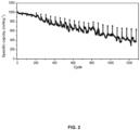
- Example 3 According to Example 3 and Comparative Example 1, AA steel housing batteries were prepared with a designed capacity of 1500 mAh, and cycle tests were performed on the AA steel housing batteries. The test results are shown in FIG. 1 . A long cycle curve of the battery of Example 3 is shown in FIG. 2 .
Landscapes
- Chemical & Material Sciences (AREA)
- Chemical Kinetics & Catalysis (AREA)
- Electrochemistry (AREA)
- General Chemical & Material Sciences (AREA)
- Engineering & Computer Science (AREA)
- Materials Engineering (AREA)
- Composite Materials (AREA)
- Manufacturing & Machinery (AREA)
- Inorganic Chemistry (AREA)
- Battery Electrode And Active Subsutance (AREA)
- Cell Electrode Carriers And Collectors (AREA)
- Secondary Cells (AREA)
Abstract
Description
- The present disclosure relates to the technical field of secondary batteries, and in particular to a composite current collector for a zinc secondary battery and a preparation method thereof, a negative electrode plate, and a zinc secondary battery.
- Zinc is a good negative electrode material for batteries. Due to the high content on earth, low price, non-toxicity and environmental friendliness, zinc has good application prospects in many types of batteries. Zinc or zinc compounds can be used as electrode materials for primary and secondary batteries. For secondary batteries, those using a zinc negative electrode, such as a zinc-nickel battery, a zinc-manganese battery, etc. also have the characteristics of high power density and good rate performance.
- However, zinc secondary batteries also have obvious disadvantages, resulting in a low level of industrialization. The main disadvantage is poor cycle performance. During the battery cycle, zinc dendrites grow on the surface of the zinc negative electrode and pierce the diaphragm, causing a short circuit in the battery, deteriorating the battery performance, and seriously affecting the cycle life of the battery. In addition, the zinc negative electrode may dissolve and deform, resulting in the inability to guarantee charge and discharge performance.
- In order to solve the problems of the zinc negative electrode, an active material of the zinc negative electrode or the diaphragm may be generally improved to improve the cycle performance of the battery. However, the effects of such measures are very limited.
- The objective of the present disclosure is to provide a composite current collector for a zinc secondary battery and a preparation method thereof, a negative electrode plate, and a zinc secondary battery, so as to improve the cycle performance of the zinc secondary battery.
- In order to achieve the above objective, the technical solution adopted by the present disclosure is as follows. The composite current collector for the zinc secondary battery may comprise a substrate, a conductive layer disposed on the substrate, two metal layers, and a carbon cloth layer disposed between the two metal layers. Each of the two metal layers may include a zinc mesh. Mesh pores of the zinc mesh and/or a carbon cloth of the carbon cloth layer may be filled with tin. The conductive layer may include a conductive polymer or a conductive carbon material.
- In some embodiments, the conductive polymer may be any one of polyaniline, polypyrrole, or polythiophene.
- The present disclosure provides a preparation method of a composite current collector for a zinc secondary battery, comprising the following steps. In step 1), a layer of carbon cloth is disposed between two layers of zinc mesh, the two layers of zinc mesh are thermally pressed with the carbon cloth, and then the two layers of zinc mesh with the carbon cloth are rolled to obtain a pressed zinc mesh. A reduction rate of the two layers of zinc mesh during rolling is within a range of 10%-50%. In step 2), the pressed zinc mesh is soaked in a graphene dispersion, then the pressed zinc mesh is taken out and dried. In step 3), two surfaces of the pressed zinc mesh dried in the step 2) are coated with a conductive paste and the pressed zinc mesh is dried to obtain the composite current collector for the zinc secondary battery. The conductive paste contains a conductive polymer.
- In some embodiments, the zinc mesh in the step 1) may be a composite zinc mesh, and the composite zinc mesh may be prepared by a method comprising the following steps. Tin powder is filled in mesh pores of the zinc mesh. The zinc mesh filled with the tin powder is kept at 250 °C-400 °C for 20 mins-50 mins in an inert atmosphere to obtain the composite zinc mesh.
- In some embodiments, an aperture of a mesh pore of the zinc mesh may be within a range of 0.5 mm-3 mm; and a particle size of the tin powder may be within a range of 100 mesh-200 mesh.
- In some embodiments, the carbon cloth in the step 1) may be a composite carbon cloth. The composite carbon cloth may be obtained by filling tin powder in pores of the carbon cloth.
- In some embodiments, a pressure of thermal pressing in the step 1) may be within a range of 1 MPa-10 MPa, and a temperature during thermal pressing may be within a range of 60 °C-120 °C.
- In some embodiments, soaking time in the step 2) may be within a range of 2 h-8 h.
- In some embodiments, a mass fraction of graphene in the graphene dispersion in the step 2) may be within a range of 0.1%-15%.
- In some embodiments, the conductive paste in the step 3) may be obtained by uniformly mixing water with the conductive polymer, a conductive carbon material, and a binder. A mass ratio of the conductive polymer, the conductive carbon material, and the binder may be within a range of 0.5-20: 0.5-10: 0.1-5.
- In some embodiments, the conductive carbon material may be any one of Ketjen black or acetylene black.
- The present disclosure provides a negative electrode plate for a zinc secondary battery. The negative electrode plate for the zinc secondary battery may comprise a current collector and a negative electrode material layer disposed on a surface of the current collector. The current collector may be the composite current collector for the zinc secondary battery described above.
- In some embodiments, the negative electrode material layer may include a negative electrode active material and a binder. The negative electrode active material may be at least one of zinc oxide, zinc, or calcium zincate.
- The present disclosure provides a zinc secondary battery, comprising a housing and a positive electrode plate, a negative electrode plate, and an electrolyte disposed in the housing. The negative electrode plate may be the negative electrode plate for the zinc secondary battery described above.
- In some embodiments, the zinc secondary battery may be any one of a zinc-nickel secondary battery or a zinc-manganese secondary battery.
- The beneficial effects that may be brought by the embodiments of the present disclosure include the following content. According to the composite current collector for the zinc secondary battery, the two metal layers are made by compositing the zinc mesh and the tin, and the carbon cloth is disposed between the two metal layers, such that corrosion of a zinc negative electrode during use of the battery is fundamentally reduced while ensuring the conductivity of the current collector, and the cycle performance of the battery is greatly improved.
-
-
FIG. 1 is a comparison diagram illustrating cycle curves of zinc secondary batteries prepared in Example 3 and Comparative Example 1; and -
FIG. 2 is a diagram illustrating a long cycle curve of a zinc secondary battery prepared in Example 3. - The zinc secondary battery of the present disclosure is any one of a zinc-nickel secondary battery or a zinc-manganese secondary battery. Any secondary battery using a zinc negative electrode plate as a negative electrode is applicable. The zinc negative electrode plate refers to a negative electrode plate containing at least one of zinc oxide, zinc, or calcium zincate in an active material of the negative electrode.
- The composite current collector for the zinc secondary battery may comprise a substrate, a conductive layer disposed on the substrate, two metal layers, and a carbon cloth layer disposed between the two metal layers. Each of the two metal layers may include a zinc mesh. Mesh pores of the zinc mesh and/or a carbon cloth of the carbon cloth layer may be filled with tin. The conductive layer may include a conductive polymer or a conductive carbon material.
- The tin filled in the mesh pores of the zinc mesh refers to metal tin. The metal tin may be fixed to the zinc mesh. The fixing may be similar to welding or melting together. An aperture of a mesh pore of the zinc mesh may be within a range of 0.5 mm-3 mm. The conductive polymer may be any one of polyaniline, polypyrrole, or polythiophene. The conductive carbon material may be any one of Ketjen black or acetylene black. Filling tin into the mesh pores of the carbon cloth refers to filling tin powder into the pores of the carbon cloth.
- The preparation method of the composite current collector for the zinc secondary battery of the present disclosure may comprise the following steps. In step 1), a layer of carbon cloth is disposed between the two layers of zinc mesh, the two layers of zinc mesh are thermally pressed with the carbon cloth, and then the two layers of zinc mesh with the carbon cloth are rolled to obtain a pressed zinc mesh. A reduction rate of the two layers of zinc mesh during rolling is within a range of 10%-50%. In step 2), the pressed zinc mesh is soaked in a graphene dispersion, then the pressed zinc mesh is taken out and dried. In step 3), two surfaces of the pressed zinc mesh dried in the step 2) are coated with a conductive paste and the pressed zinc mesh is dried to obtain the composite current collector for the zinc secondary battery. The conductive paste contains a conductive polymer.
- The zinc mesh in the step 1) may be a composite zinc mesh. The composite zinc mesh may be prepared by a method comprising the following steps. Tin powder is filled in the mesh pores of the zinc mesh. The zinc mesh filled with the tin powder is kept at 250 °C-400 °C for 20 mins-50 mins in an inert atmosphere to obtain the composite zinc mesh.
- When the zinc mesh is filled with the tin powder in the step 1), a polymer film may be bonded to one surface of the zinc mesh, and the zinc mesh may be laid flat with a side of the zinc mesh bonded with the polymer film facing downward and the other side facing upward; and the tin powder is sprinkled on the zinc mesh and scraped flat.
- The zinc mesh may be a diagonal zinc mesh or a punched zinc mesh. The aperture of a mesh pore of the zinc mesh may be within a range of 0.5 mm-3 mm. A particle size of the tin powder may be within a range of 100 mesh-200 mesh. The polymer film may be a polyethylene film or a polypropylene film.
- The inert atmosphere in the step 1) may be nitrogen or argon. After keeping the zinc mesh filled with the tin powder at 250 °C-400 °C for 20 min-50 min in the inert atmosphere, the zinc mesh filled with the tin powder may be naturally cooled to room temperature in the inert atmosphere.
- A pressure of thermal pressing in the step 1) may be within a range of 1 MPa-10Mpa. Preferably, the pressure of thermal pressing in the step 1) may be within a range of 2 MPa-5 MPa. A temperature during thermal pressing may be within a range of 60 °C-120 °C. Preferably, the temperature during thermal pressing may be within a range of 80 °C -100 °C. The reduction rate may include deformation caused by pressing during thermal pressing and rolling.
- Soaking time in the step 2) may be within a range of 2 h-8 h. Preferably, the soaking time in the step 2) may be within a range of 2 h-5 h. A mass fraction of graphene in the graphene dispersion may be within a range of 0.1%-15%. In some embodiments, the mass fraction of the graphene in the graphene dispersion may be within a range of 1%-10%. The pressed zinc mesh after soaking may be taken out and vacuum dried. A temperature of vacuum drying may be within a range of 40 °C-100 °C.
- The conductive polymer in the step 3) may be any one of polyaniline, polypyrrole, or polythiophene. The conductive paste may also contain the conductive carbon material. The conductive carbon material may be any one of Ketjen black or acetylene black.
- In some embodiments, the conductive paste in the step 3) may be obtained by uniformly mixing water with a conductive polymer, the conductive carbon material, and a binder. A mass ratio of the conductive polymer, the conductive carbon material, and the binder may be within a range of 0.5-20: 0.5-10: 0.1-5. Preferably, the mass ratio of the conductive polymer, the conductive carbon material, and the binder may be within a range of 1-8:0.5-5:2-3.
- The binder may be at least one of polytetrafluoroethylene, polyvinylidene fluoride, carboxymethyl cellulose, or styrene-butadiene rubber latex. After the conductive paste is coated on the two surfaces of the pressed zinc mesh, vacuum drying may be performed. A temperature of vacuum drying may be within a range of 60 °C-80 °C. Drying time may be within a range of 2 h-8 h.
- The negative electrode plate for the zinc secondary battery of the present disclosure may comprise a current collector and a negative electrode material layer disposed on a surface of the current collector. The current collector may be the composite current collector for the zinc secondary battery.
- The negative electrode material layer may include a negative electrode active material and a binder. The negative electrode active material may be at least one of zinc oxide, zinc, or calcium zincate. In some embodiments, the negative electrode material layer may include zinc oxide, zinc, indium oxide, bismuth oxide, tin oxide, polytetrafluoroethylene, sodium polyacrylate, glycerol, and sodium dihydrogen phosphate, and a mass ratio of the zinc oxide, the zinc, the indium oxide, the bismuth oxide, the tin oxide, the polytetrafluoroethylene, the sodium polyacrylate, the glycerol, and the sodium dihydrogen phosphate is 63:21:0.2:2:3:5:0.25: 1: 1.
- The zinc secondary battery of the present disclosure may comprise a housing and a positive electrode plate, a negative electrode plate, and an electrolyte disposed in the housing. The negative electrode plate may be the negative electrode plate for the zinc secondary battery as described above.
- A preparation method of a composite current collector for a zinc secondary battery of the Example 1 comprises the following steps.
- In step 1), a polymer film was bonded to one surface of a zinc mesh, and the zinc mesh was laid flat with a side of the zinc mesh bonded with the polymer film facing downward and the other side facing upward; tin powder was sprinkled on the zinc mesh, , a particle size of the tin powder being 100 mesh, and a mesh diameter of the zinc mesh being 1 mm; the surface of the zinc mesh was scraped flat, a layer of polymer film was bonded to the upper surface of the zinc mesh, the polymer film was a polyethylene film; and the processed zinc mesh was kept at 350 °C for 30 min in an inert atmosphere, and then naturally cooled to a room temperature in the inert atmosphere to obtain a composite zinc mesh.
- In step 2), the composite zinc mesh was folded in half and a carbon cloth was disposed therebetween, and a size of the carbon cloth was slightly greater than half of the zinc mesh, such that a portion of the carbon cloth was exposed on three sides of the zinc mesh with the carbon cloth; the zinc mesh with the carbon cloth was thermally pressed, a pressure of thermal pressing being 2 Mpa, and a temperature during thermal pressing being 80 °C; and then the thermally pressed zinc mesh was placed on a roller press for rolling, and the rolling was stopped until a reduction rate of the zinc mesh was about 30% to obtain a pressed zinc mesh.
- In step 3), the pressed zinc mesh was soaked in a graphene dispersion for 2 h, the graphene dispersion being obtained by uniformly dispersing graphene and water in a mass ratio of 5: 95; and the pressed zinc mesh after soaking was taken out, and vacuum dried at 40° C.
- In step 4), polyaniline, Ketjen black, carboxymethyl cellulose, and water in a mass ratio of 8: 5: 3: 84 were uniformly mixed to obtain a conductive paste, and the conductive paste was coated on two surfaces of the pressed zinc mesh and vacuum dried at 60 °C for 3 h to obtain the composite current collector.
- The negative electrode plate for the zinc secondary battery of the Example 1 comprises a current collector and a negative electrode material layer disposed on a surface of the current collector. The current collector is the composite current collector for the zinc secondary battery. The negative electrode material layer is formed by coating and drying a negative electrode paste on the current collector. The negative electrode paste is obtained by uniformly mixing zinc oxide, zinc, indium oxide, bismuth oxide, tin oxide, polytetrafluoroethylene, sodium polyacrylate, glycerol, sodium dihydrogen phosphate, and water in a mass ratio of 63:21:0.2:2:3:5:0.25:1:1:5.
- The preparation method of the negative electrode plate for the zinc secondary battery of the Example 1 comprises the following steps.
- In step S1, a conductive paste was obtained by uniformly mixing zinc oxide, zinc, indium oxide, bismuth oxide, tin oxide, polytetrafluoroethylene, sodium polyacrylate, glycerol, sodium dihydrogen phosphate, and water in a mass ratio of 63:21:0.2:2:3:5:0.25:1:1:5.
- In step S2, the composite current collector for the zinc secondary battery was taken, and two surfaces of the composite current collector were coated with a negative electrode paste, and the composite current collector coated with the negative electrode paste was dried, rolled, and cut to obtain the negative electrode plate for the zinc secondary battery.
- The zinc secondary battery of the Example 1 is a zinc-nickel battery, comprising a cylindrical steel housing (AAA). A battery cell and an electrolyte are disposed in the steel housing. The battery cell is made by stacking and winding a positive electrode plate, a diaphragm, a negative electrode plate, and a diaphragm in sequence. The negative electrode plate is the negative electrode plate described above. The positive electrode plate includes a positive current collector. The positive current collector is a nickel strip. Two surfaces of the positive current collector are coated with a positive electrode material layer. The positive electrode material layer includes a positive electrode active substance, a binder, etc. The positive electrode active substance is nickel hydroxide.
- A preparation method of a composite current collector for a zinc secondary battery of the Example 2 comprises the following steps.
- In step 1), A polymer film was bonded to one surface of a zinc mesh, and the zinc mesh was laid flat with a side of the zinc mesh bonded with the polymer film facing downward and the other side facing upward; a slight amount of polyethylene powder (D50 about 150 µm) was sprinkled on the zinc mesh, the polyethylene powder was scraped into mesh pores of the zinc mesh using a scraper, and an amount of the polyethylene powder was such that a height of the polyethylene powder in the mesh pores was about 1/3 of a thickness of the zinc mesh; tin powder was sprinkled on the zinc mesh, a particle size of the tin powder being 100 mesh, a mesh diameter of the zinc mesh being 1 mm, the surface of the zinc mesh was scraped flat, and a layer of polymer film was bonded to the upper surface of the zinc mesh, the polymer film being a polyethylene film; and a processed zinc mesh was kept at 400 °C for 22 min in an inert atmosphere, and then naturally cooled to a room temperature in the inert atmosphere to obtain a composite zinc mesh, the side of the zinc mesh sprinkled with the polyethylene powder facing upward at the temperature of 400 °C.
- In step 2), the composite zinc mesh was folded in half and a carbon cloth was disposed therebetween, and a size of the carbon cloth was slightly greater than half of the zinc mesh, such that a portion of the carbon cloth was exposed on three sides of the zinc mesh with the carbon cloth; the zinc mesh with the carbon cloth was thermally pressed, a pressure of thermal pressing being 5 Mpa, and a temperature during thermal pressing being 100 °C; and then the thermally pressed zinc mesh was placed on a roller press for rolling, and the rolling was stopped until a reduction rate of the zinc mesh was about 26% to obtain a pressed zinc mesh.
- In step 3), the pressed zinc mesh was soaked in a graphene dispersion for 6 h, the graphene dispersion being obtained by uniformly dispersing graphene and water in a mass ratio of 10: 90; and the pressed zinc mesh after soaking was taken out, and vacuum dried at 55° C.
- In step 4), polyaniline, Ketjen black, carboxymethyl cellulose, and water in a mass ratio of 5: 3: 2: 9 were uniformly mixed to obtain a conductive paste, and the conductive paste was coated on two surfaces of the pressed zinc mesh and vacuum dried at 80 °C for 2 h to obtain the composite current collector.
- The negative electrode plate for the zinc secondary battery of the Example 2 comprises a current collector and a negative electrode material layer disposed on a surface of the current collector. The current collector is the composite current collector for the zinc secondary battery. The negative electrode material layer is formed by coating and drying a negative electrode paste on the current collector. The negative electrode paste is obtained by uniformly mixing zinc oxide, zinc, indium oxide, bismuth oxide, tin oxide, polytetrafluoroethylene, sodium polyacrylate, glycerol, sodium dihydrogen phosphate, and water in a mass ratio of 63:21:0.2:2:3:5:0.25:1:1:5.
- The preparation method of the negative electrode plate for the zinc secondary battery of the Example 2 comprises the following steps.
- In step S1, zinc oxide, zinc, indium oxide, bismuth oxide, tin oxide, polytetrafluoroethylene, sodium polyacrylate, glycerol, sodium dihydrogen phosphate, and water in a mass ratio of 63:21:0.2:2:3:5:0.25:1:1:5 were uniformly mixed to obtain a conductive paste.
- In step S2, the composite current collector for the zinc secondary battery was taken, and two surfaces of the composite current collector were coated with a negative electrode paste, and the composite current collector coated with the negative electrode paste was dried, rolled, and cut to obtain the negative electrode plate for the zinc secondary battery.
- The zinc secondary battery of the Example 2 is a zinc-nickel battery, comprising a cylindrical steel housing (AAA). A battery cell and an electrolyte are disposed in the steel housing. The battery cell is made by stacking and winding a positive electrode plate, a diaphragm, a negative electrode plate, and a diaphragm in sequence. The negative electrode plate is the negative electrode plate described above. The positive electrode plate includes a positive current collector. The positive current collector is a nickel strip. Two surfaces of the positive current collector are coated with a positive electrode material layer. The positive electrode material layer includes a positive electrode active substance, a binder, etc. The positive electrode active substance is nickel hydroxide.
- A preparation method of a composite current collector for a zinc secondary battery of the Example 3 comprises the following steps.
- In step 1), a polymer film was bonded to one surface of a zinc mesh, and the zinc mesh was laid flat with a side of the zinc mesh bonded with the polymer film facing downward and the other side facing upward; a slight amount of polyethylene powder (D50 about 150 µm) was sprinkled on the zinc mesh, the polyethylene powder was scraped into mesh pores of the zinc mesh using a scraper, and an amount of the polyethylene powder was such that a height of the polyethylene powder in the mesh pores was about 1/3 of a thickness of the zinc mesh; tin powder was sprinkled on the zinc mesh a particle size of the tin powder being 100 mesh, and a mesh diameter of the zinc mesh being 0.8 mm, the surface of the zinc mesh was scraped flat, and a layer of polymer film was bonded to the upper surface of the zinc mesh, the polymer film being a polyethylene film; and a processed zinc mesh was kept at 405 °C for 20 min in an inert atmosphere, and then naturally cooled to a room temperature in the inert atmosphere to obtain a composite zinc mesh, the side of the zinc mesh sprinkled with the polyethylene powder facing upward at the temperature of 405 °C.
- In step 2), the composite zinc mesh was folded in half and a carbon cloth was disposed therebetween, and a size of the carbon cloth was slightly greater than half of the zinc mesh, such that a portion of the carbon cloth was exposed on three sides of the zinc mesh with the carbon cloth; the zinc mesh with the carbon cloth was thermally pressed, a pressure of thermal pressing being 3.5 Mpa, and a temperature during thermal pressing being 85 °C; and then the thermally pressed zinc mesh was placed on a roller press for rolling, and the rolling was stopped until a reduction rate of the zinc mesh was about 30% to obtain a pressed zinc mesh;
- In step 3), the pressed zinc mesh was soaked in a graphene dispersion for 5 h, the graphene dispersion being obtained by uniformly dispersing graphene and water in a mass ratio of 1: 99; and the pressed zinc mesh after soaking was taken out, and vacuum dried at 45° C.
- In step 4), polyaniline, Ketjen black, carboxymethyl cellulose, and water in a mass ratio of 3: 4.5: 2.5: 90 were uniformly mixed to obtain a conductive paste, and the conductive paste was coated on two surfaces of the pressed zinc mesh and vacuum dried at 70 °C for 2 h to obtain the composite current collector.
- The negative electrode plate for the zinc secondary battery of the Example 2 comprises a current collector and a negative electrode material layer disposed on a surface of the current collector. The current collector is the composite current collector for the zinc secondary battery. The negative electrode material layer is formed by coating and drying a negative electrode paste on the current collector. The negative electrode paste is obtained by uniformly mixing zinc oxide, zinc, indium oxide, bismuth oxide, tin oxide, polytetrafluoroethylene, sodium polyacrylate, glycerol, sodium dihydrogen phosphate, and water in a mass ratio of 63:21:0.2:2:3:5:0.25:1:1:5.
- The preparation method of the negative electrode plate for the zinc secondary battery of the Example 3 comprises the following steps.
- In step S1, zinc oxide, zinc, indium oxide, bismuth oxide, tin oxide, polytetrafluoroethylene, sodium polyacrylate, glycerol, sodium dihydrogen phosphate, and water in a mass ratio of 63:21:0.2:2:3:5:0.25:1:1:5 were uniformly mixed to obtain a conductive paste;
- In step S2, the composite current collector for the zinc secondary battery was taken, and two surfaces of the composite current collector were coated with a negative electrode paste, and the composite current collector coated with the negative electrode paste was dried, rolled and cut to obtain the negative electrode plate for the zinc secondary battery.
- The zinc secondary battery of the Example 3 is a zinc-nickel battery, comprising a cylindrical steel housing (AA). A battery cell and an electrolyte are disposed in the steel housing. The battery cell is made by stacking and winding a positive electrode plate, a diaphragm, a negative electrode plate, and a diaphragm in sequence. The negative electrode plate is the negative electrode plate described above. The positive electrode plate includes a positive current collector. The positive current collector is a nickel strip. Two surfaces of the positive current collector are coated with a positive electrode material layer. The positive electrode material layer includes a positive electrode active substance, a binder, etc. The positive electrode active substance is nickel hydroxide.
- In the Example 4, based on the Example 3, when a negative electrode plate was prepared, the obtained negative electrode plate for the zinc secondary battery was soaked in a graphene dispersion for 1 h-2 h, and then taken out and dried, such that a graphene layer was deposited on a surface of a negative electrode material layer.
- The zinc secondary battery of the Example 4 is a zinc-nickel battery. More descriptions regarding the zinc-nickel battery are found in f Example 3.
- The difference between the Example 5 and Example 1 is that, in the Example 5, mesh pores of a zinc mesh is no longer filled with tin powder, but a punched zinc mesh is directly used to replace the composite zinc mesh, and a carbon cloth is preprocessed before use. The preprocessing includes the following steps: flattening the carbon cloth, sprinkling the tin powder on a surface of the carbon cloth, a particle size of the tin powder being 200 mesh, and then scraping the surface of the carbon cloth with a scraper back and forth to fill the tin powder into the woven mesh pores of the carbon cloth, so as to obtain a composite carbon cloth to replace the carbon cloth in the step 2) of Example 1.
- The zinc secondary battery of the Example 5 is a zinc-nickel battery. More descriptions regarding the zinc-nickel battery are found in Example 3.
- The difference between the Comparative Example 1 and Example 1 is that the same zinc mesh as in Example 1 is used as a current collector, and the remaining parts are the same as in Example 1.
-
(1) According to Example 3, 10 AA steel housing batteries were prepared with a designed capacity of 1500 mAh, and electrochemical tests were performed on the 10 AA steel housing batteries. The test results are shown in the following table.Example 3 Battery No. Internal resistance after capacitan ce division Volage after capacita nce division Internal resistan ce after 28 days at 60 °C Voltage after 28 days at 60 °C M1 capacity M2 capacity M3 capacity Retention rate of charge Recovery rate of capacity 11 24.6 1.854 25.2 1.695 1449.86 1055.43 1351.68 72.8% 93.2% 12 25.9 1.851 26.5 1.688 1441.93 1009.97 1351.71 70.0% 93.7% 13 27.7 1.854 28.6 1.687 1447.58 1024.18 1376.29 70.8% 95.1% 14 24.9 1.855 25.5 1.695 1455.45 1066.67 138536 73.3% 95.2% 15 24.8 1.854 25.4 1.696 1468.8 1064.53 1400.77 72.5% 95.4% 16 24.8 1.853 25.5 1.696 1460.39 1063.91 1391.6 72.9% 95.3% 17 26.4 1.854 27.4 1.69 1442.15 1051.83 1365.44 72.9% 94.7% 18 24.8 1.854 25.4 1.692 1461.29 1053.91 1391.59 72.1% 95.2% 19 25.5 1.853 26.2 1.692 1460.66 1035.16 1382.42 70.9% 94.6% 20 26 1.852 26.9 1.685 1477.95 1032.03 1403.48 69.8% 95.0% Average 25.54 1.853 26.26 1.692 1457 1046 1380 71.8% 94.7% - According to Comparative Example 1, 10 AA steel housing batteries were prepared with a designed capacity of 1500 mAh, and electrochemical tests were performed on the 10 AA steel housing batteries. The test results are shown in the following table.
Comparative Example 1 Battery No. Internal resistance after capacitan ce division Volage after capacita nce division Internal resistan ce after 28 days at 60 °C Voltage after 28 days at 60 °C M1 capacity M2 capacity M3 capacity Retention rate of charge Recovery rate of capacity 21 25.9 1.847 26.8 1.695 1449.81 949.16 1334.21 65.5% 92.0% 22 25.5 1.847 26 1.688 1445.06 942.49 1340.06 65.2% 92.7% 23 25.5 1.848 26.1 1.676 1437.99 876.26 1327.25 60.9% 92.3% 24 26 1.848 26.5 1.698 1445.07 967.28 1339.32 66.9% 92.7% 25 25.7 1.847 26.3 1.698 1457.58 987.69 1354.85 67.8% 93.0% 26 25.2 1.848 25.6 1.697 1447.57 971.02 1337.02 67.1% 92.4% 27 25.3 1.847 25.9 1.69 1444.03 946.86 1329.74 65.6% 92.1% 28 25.4 1.848 26.4 1.693 1475.23 917.7 1353.82 62.2% 91.8% 29 26 1.847 26.9 1.688 1431.99 898.89 1306.22 62.8% 91.2% 30 24.8 1.848 25.5 1.694 1461.52 963.67 1361.63 65.9% 93.2% Average 25.53 1.848 26.2 1.692 1450 942 1338 65.0% 92.3% - (2) According to Example 3 and Comparative Example 1, AA steel housing batteries were prepared with a designed capacity of 1500 mAh, and cycle tests were performed on the AA steel housing batteries. The test results are shown in
FIG. 1 . A long cycle curve of the battery of Example 3 is shown inFIG. 2 .
Claims (10)
- A composite current collector for a zinc secondary battery, comprising a substrate, a conductive layer disposed on the substrate, two metal layers, and a carbon cloth layer disposed between the two metal layers, wherein:each of the two metal layers includes a zinc mesh, and mesh pores of the zinc mesh and/or a carbon cloth of the carbon cloth layer are filled with tin; andthe conductive layer includes a conductive polymer or a conductive carbon material.
- The composite current collector for the zinc secondary battery of claim 1, wherein the conductive polymer is any one of polyaniline, polypyrrole, or polythiophene.
- A preparation method of a composite current collector for a zinc secondary battery, comprising the following steps:1) disposing a layer of carbon cloth between two layers of zinc mesh thermally pressing the two layers of zinc mesh with the carbon cloth, and rolling the two layers of zinc mesh with the carbon cloth to obtain a pressed zinc mesh, a reduction rate of the two layers of zinc mesh during rolling being within a range of 10-50%;2) soaking the pressed zinc mesh in a graphene dispersion, then taking out and drying the pressed zinc mesh; and3) coating two surfaces of the pressed zinc mesh dried in the step 2) with a conductive paste and drying to obtain the composite current collector for the zinc secondary battery, the conductive paste containing a conductive polymer.
- The preparation method of claim 3, wherein the zinc mesh in the step 1) is a composite zinc mesh, and the composite zinc mesh is prepared by a method comprising the following steps:filling tin powder in mesh pores of the zinc mesh; andkeeping the zinc mesh filled with the tin powder at 250 °C-400 °C for 20 mins-50 mins in an inert atmosphere to obtain the composite zinc mesh.
- The preparation method of claim 3, wherein the carbon cloth in the step 1) is a composite carbon cloth, and the composite carbon cloth is obtained by filling tin powder in pores of the carbon cloth.
- The preparation method of claim 3, wherein a mass fraction of graphene in the graphene dispersion in the step 2) is within a range of 0.1%-15%.
- The preparation method of any one of claims 3-6, wherein the conductive paste in the step 3) is obtained by uniformly mixing water with the conductive polymer, a conductive carbon material, and a binder, a mass ratio of the conductive polymer, the conductive carbon material, and the binder being within a range of 0.5-20: 0.5-10: 0.1-5.
- A negative electrode plate for a zinc secondary battery, comprising a current collector and a negative electrode material layer disposed on a surface of the current collector, wherein the current collector is the composite current collector for the zinc secondary battery of claim 1.
- The negative electrode plate for the zinc secondary battery of claim 8, wherein the negative electrode material layer includes a negative electrode active material and a binder, and the negative electrode active material is at least one of zinc oxide, zinc, or calcium zincate.
- A zinc secondary battery, comprising a housing and a positive electrode plate, a negative electrode plate, and an electrolyte disposed in the housing, wherein the negative electrode plate is the negative electrode plate for the zinc secondary battery of claim 11.
Applications Claiming Priority (2)
| Application Number | Priority Date | Filing Date | Title |
|---|---|---|---|
| CN202210018880.XA CN114976028B (en) | 2022-01-10 | 2022-01-10 | Composite current collector for zinc secondary battery and preparation method thereof, negative electrode sheet, and zinc secondary battery |
| PCT/CN2023/070012 WO2023131100A1 (en) | 2022-01-10 | 2023-01-02 | Composite current collector for zinc secondary battery and preparation method therefor, negative electrode plate and zinc secondary battery |
Publications (2)
| Publication Number | Publication Date |
|---|---|
| EP4465388A1 true EP4465388A1 (en) | 2024-11-20 |
| EP4465388A4 EP4465388A4 (en) | 2025-10-15 |
Family
ID=82974530
Family Applications (1)
| Application Number | Title | Priority Date | Filing Date |
|---|---|---|---|
| EP23736965.7A Pending EP4465388A4 (en) | 2022-01-10 | 2023-01-02 | Composite current collector for a zinc secondary battery and manufacturing method therefor, negative electrode plate and zinc secondary battery |
Country Status (5)
| Country | Link |
|---|---|
| US (1) | US12347869B2 (en) |
| EP (1) | EP4465388A4 (en) |
| JP (1) | JP7823847B2 (en) |
| CN (1) | CN114976028B (en) |
| WO (1) | WO2023131100A1 (en) |
Families Citing this family (3)
| Publication number | Priority date | Publication date | Assignee | Title |
|---|---|---|---|---|
| CN114976028B (en) | 2022-01-10 | 2024-05-24 | 河南超力新能源有限公司 | Composite current collector for zinc secondary battery and preparation method thereof, negative electrode sheet, and zinc secondary battery |
| CN117577850A (en) * | 2023-10-31 | 2024-02-20 | 江阴纳力新材料科技有限公司 | A double-layer carbon-coated current collector and its preparation method, pole piece, and battery |
| KR102945870B1 (en) | 2026-01-14 | 2026-03-31 | 디에이치 주식회사 | 3D foam for prevention and delay thermal runaway in batteries using metal mesh-polymer slurry and its manufacturing method |
Family Cites Families (25)
| Publication number | Priority date | Publication date | Assignee | Title |
|---|---|---|---|---|
| CA2513454C (en) * | 2002-02-12 | 2015-09-01 | Eveready Battery Company, Inc. | Flexible thin printed battery with gelled electrolyte and method of manufacturing same |
| US6673494B2 (en) * | 2002-02-15 | 2004-01-06 | Alltrista Zinc Products, L.P. | Expanded zinc mesh anode |
| JP2005222880A (en) | 2004-02-09 | 2005-08-18 | Hitachi Maxell Ltd | Sheet-like zinc electrode and alkaline battery using the same |
| US7291186B2 (en) | 2004-11-01 | 2007-11-06 | Teck Cominco Metals Ltd. | Solid porous zinc electrodes and methods of making same |
| US7976976B2 (en) * | 2007-02-07 | 2011-07-12 | Rosecreek Technologies Inc. | Composite current collector |
| CN101026234A (en) * | 2007-02-12 | 2007-08-29 | 范正刚 | Zinc-nickel battery negative plate |
| US7986509B2 (en) * | 2008-01-17 | 2011-07-26 | Fraser Wade Seymour | Composite electrode comprising a carbon structure coated with a thin film of mixed metal oxides for electrochemical energy storage |
| JP2014149993A (en) * | 2013-02-01 | 2014-08-21 | Nippon Shokubai Co Ltd | Zinc negative electrode, battery and electrode base layer |
| CN103825011B (en) * | 2014-02-28 | 2016-04-06 | 苏州路特新能源科技有限公司 | The tin of lithium ion battery and the preparation method of conducting polymer composite negative pole material film |
| US20160204441A1 (en) * | 2014-09-02 | 2016-07-14 | Panisolar, Inc. | Wall Mounted Zinc Batteries |
| CN104805324B (en) * | 2015-04-08 | 2017-01-11 | 河海大学 | Method for preparing foam zinc-based material through powder metallurgic method |
| CN105336971B (en) * | 2015-09-25 | 2018-08-17 | 中国人民解放军63971部队 | Water-system zinc-manganese single flow battery |
| JP6662353B2 (en) | 2017-07-18 | 2020-03-11 | トヨタ自動車株式会社 | Negative electrode current collector, negative electrode, and aqueous lithium ion secondary battery |
| CN108091881A (en) * | 2017-12-28 | 2018-05-29 | 上海应用技术大学 | A kind of preparation method of carbon film-M collectors |
| WO2020086838A1 (en) | 2018-10-24 | 2020-04-30 | Urban Electric Power Inc. | Porous zn metal electrode for zn batteries |
| CN109817879B (en) * | 2019-03-19 | 2020-08-14 | 北京航空航天大学 | Zinc metal composite electrode with array structure and preparation method thereof |
| CN110190344B (en) * | 2019-06-13 | 2022-02-11 | 深圳市寒暑科技新能源有限公司 | Flexible water-based zinc ion battery |
| CN110600746A (en) * | 2019-09-24 | 2019-12-20 | 河南超力新能源有限公司 | Composite current collector for zinc-based battery, preparation method of composite current collector, negative plate and zinc-based battery |
| CN211556038U (en) * | 2019-09-24 | 2020-09-22 | 河南超力新能源有限公司 | Composite current collector for zinc-based battery, negative plate and zinc-based battery |
| JP7535127B2 (en) * | 2020-06-30 | 2024-08-15 | 寧徳新能源科技有限公司 | Bipolar current collectors, electrochemical devices and electronic devices |
| RU2758442C1 (en) | 2020-12-08 | 2021-10-28 | Федеральное государственное бюджетное учреждение науки Институт проблем химической физики Российской Академии наук (ФГБУН ИПХФ РАН) | Composite cathode material and method for its preparation |
| WO2022165380A1 (en) * | 2021-01-29 | 2022-08-04 | Hunt Energy Enterprises, L.L.C. | Anode for zn-based batteries |
| CN113036152B (en) * | 2021-03-08 | 2022-08-23 | 山东大学 | High-energy-density and high-safety zinc metal battery without negative electrode and preparation method and application thereof |
| CN113745520B (en) * | 2021-09-05 | 2022-12-13 | 浙江大学 | Preparation method and application of zinc cathode material for inhibiting zinc dendrites |
| CN114976028B (en) * | 2022-01-10 | 2024-05-24 | 河南超力新能源有限公司 | Composite current collector for zinc secondary battery and preparation method thereof, negative electrode sheet, and zinc secondary battery |
-
2022
- 2022-01-10 CN CN202210018880.XA patent/CN114976028B/en active Active
-
2023
- 2023-01-02 WO PCT/CN2023/070012 patent/WO2023131100A1/en not_active Ceased
- 2023-01-02 EP EP23736965.7A patent/EP4465388A4/en active Pending
- 2023-01-02 JP JP2024541910A patent/JP7823847B2/en active Active
-
2024
- 2024-07-10 US US18/768,034 patent/US12347869B2/en active Active
Also Published As
| Publication number | Publication date |
|---|---|
| CN114976028A (en) | 2022-08-30 |
| WO2023131100A1 (en) | 2023-07-13 |
| CN114976028B (en) | 2024-05-24 |
| US12347869B2 (en) | 2025-07-01 |
| JP7823847B2 (en) | 2026-03-04 |
| US20240363869A1 (en) | 2024-10-31 |
| JP2025500684A (en) | 2025-01-09 |
| EP4465388A4 (en) | 2025-10-15 |
Similar Documents
| Publication | Publication Date | Title |
|---|---|---|
| EP4465388A1 (en) | Composite current collector for zinc secondary battery and preparation method therefor, negative electrode plate and zinc secondary battery | |
| CN110858660B (en) | Lithium-ion battery, preparation method thereof, and electric vehicle | |
| CN111370649A (en) | Preparation method of multilayer coating pole piece | |
| EP3758126A1 (en) | Battery | |
| CN111725561A (en) | A solid-state electrolyte and preparation method thereof, and all-solid-state battery | |
| WO2016045622A1 (en) | Battery, battery pack and continuous power supply | |
| WO2025082548A1 (en) | Positive electrode sheet and preparation method therefor, and lithium ion battery | |
| CA2389907A1 (en) | Small format, high current density flat plate rechargeable electrochemical cell | |
| CN114843438A (en) | A kind of battery pole piece and its preparation method and lithium ion battery | |
| EP4362123A1 (en) | Negative electrode sheet and battery applying same | |
| CN115548252A (en) | Negative plate and application thereof | |
| CN1434534A (en) | Zinc-nickel secondary cell and preparation method thereof | |
| KR102587795B1 (en) | Electrode for secondary battery and method for preparing the same | |
| CN114899359B (en) | Improved lithium/silicon/carbon composite negative electrode and preparation method thereof | |
| CN118841636B (en) | Preparation method of intermediate layer for all-solid-state lithium metal battery and all-solid-state lithium metal battery | |
| CN1208864C (en) | Preparation method of zinc-nickel primary battery | |
| CN117594743A (en) | A composite positive electrode, all-solid-state battery and preparation method thereof | |
| CN111952571B (en) | Lithium/lithium alloy composite negative electrode for high-power primary battery, preparation method and battery | |
| CN213150817U (en) | A copper current collector | |
| CN115799443A (en) | Sodium ion battery microporous aluminum foil electrode and preparation method thereof | |
| CN115832617A (en) | Intercalation composite film, preparation method thereof and lithium-sulfur battery | |
| CN114824195A (en) | Composite negative electrode material for zinc battery, preparation method and application thereof | |
| RU2836833C2 (en) | Composite current collectors for secondary zinc accumulators and methods of their manufacturing, plates of negative electrodes and secondary zinc accumulators | |
| RU2851657C1 (en) | Method of manufacturing a composite current collector for a secondary zinc battery, negative electrode plate and secondary zinc battery | |
| CN116995203A (en) | A multifunctional interface layer protected sodium/potassium metal negative electrode, preparation method and application thereof |
Legal Events
| Date | Code | Title | Description |
|---|---|---|---|
| STAA | Information on the status of an ep patent application or granted ep patent |
Free format text: STATUS: THE INTERNATIONAL PUBLICATION HAS BEEN MADE |
|
| PUAI | Public reference made under article 153(3) epc to a published international application that has entered the european phase |
Free format text: ORIGINAL CODE: 0009012 |
|
| STAA | Information on the status of an ep patent application or granted ep patent |
Free format text: STATUS: REQUEST FOR EXAMINATION WAS MADE |
|
| 17P | Request for examination filed |
Effective date: 20240718 |
|
| AK | Designated contracting states |
Kind code of ref document: A1 Designated state(s): AL AT BE BG CH CY CZ DE DK EE ES FI FR GB GR HR HU IE IS IT LI LT LU LV MC ME MK MT NL NO PL PT RO RS SE SI SK SM TR |
|
| DAV | Request for validation of the european patent (deleted) | ||
| DAX | Request for extension of the european patent (deleted) | ||
| A4 | Supplementary search report drawn up and despatched |
Effective date: 20250912 |
|
| RIC1 | Information provided on ipc code assigned before grant |
Ipc: H01M 4/66 20060101AFI20250908BHEP Ipc: H01M 4/24 20060101ALI20250908BHEP Ipc: H01M 4/74 20060101ALI20250908BHEP Ipc: H01M 4/02 20060101ALN20250908BHEP |