EP4465240A2 - Bildverarbeitungsvorrichtung, bildverarbeitungsverfahren und programm - Google Patents
Bildverarbeitungsvorrichtung, bildverarbeitungsverfahren und programm Download PDFInfo
- Publication number
- EP4465240A2 EP4465240A2 EP24197952.5A EP24197952A EP4465240A2 EP 4465240 A2 EP4465240 A2 EP 4465240A2 EP 24197952 A EP24197952 A EP 24197952A EP 4465240 A2 EP4465240 A2 EP 4465240A2
- Authority
- EP
- European Patent Office
- Prior art keywords
- image
- search area
- difference
- interest
- obtaining
- Prior art date
- Legal status (The legal status is an assumption and is not a legal conclusion. Google has not performed a legal analysis and makes no representation as to the accuracy of the status listed.)
- Pending
Links
Images







Classifications
-
- G—PHYSICS
- G06—COMPUTING OR CALCULATING; COUNTING
- G06T—IMAGE DATA PROCESSING OR GENERATION, IN GENERAL
- G06T7/00—Image analysis
- G06T7/20—Analysis of motion
- G06T7/254—Analysis of motion involving subtraction of images
-
- G—PHYSICS
- G06—COMPUTING OR CALCULATING; COUNTING
- G06T—IMAGE DATA PROCESSING OR GENERATION, IN GENERAL
- G06T7/00—Image analysis
- G06T7/70—Determining position or orientation of objects or cameras
-
- A—HUMAN NECESSITIES
- A61—MEDICAL OR VETERINARY SCIENCE; HYGIENE
- A61B—DIAGNOSIS; SURGERY; IDENTIFICATION
- A61B6/00—Apparatus or devices for radiation diagnosis; Apparatus or devices for radiation diagnosis combined with radiation therapy equipment
- A61B6/02—Arrangements for diagnosis sequentially in different planes; Stereoscopic radiation diagnosis
- A61B6/03—Computed tomography [CT]
-
- A—HUMAN NECESSITIES
- A61—MEDICAL OR VETERINARY SCIENCE; HYGIENE
- A61B—DIAGNOSIS; SURGERY; IDENTIFICATION
- A61B8/00—Diagnosis using ultrasonic, sonic or infrasonic waves
- A61B8/13—Tomography
- A61B8/14—Echo-tomography
-
- G—PHYSICS
- G01—MEASURING; TESTING
- G01T—MEASUREMENT OF NUCLEAR OR X-RADIATION
- G01T1/00—Measuring X-radiation, gamma radiation, corpuscular radiation, or cosmic radiation
- G01T1/16—Measuring radiation intensity
- G01T1/161—Applications in the field of nuclear medicine, e.g. in vivo counting
-
- G—PHYSICS
- G06—COMPUTING OR CALCULATING; COUNTING
- G06T—IMAGE DATA PROCESSING OR GENERATION, IN GENERAL
- G06T1/00—General purpose image data processing
-
- G—PHYSICS
- G06—COMPUTING OR CALCULATING; COUNTING
- G06T—IMAGE DATA PROCESSING OR GENERATION, IN GENERAL
- G06T5/00—Image enhancement or restoration
- G06T5/50—Image enhancement or restoration using two or more images, e.g. averaging or subtraction
-
- G—PHYSICS
- G06—COMPUTING OR CALCULATING; COUNTING
- G06T—IMAGE DATA PROCESSING OR GENERATION, IN GENERAL
- G06T5/00—Image enhancement or restoration
- G06T5/70—Denoising; Smoothing
-
- G—PHYSICS
- G06—COMPUTING OR CALCULATING; COUNTING
- G06T—IMAGE DATA PROCESSING OR GENERATION, IN GENERAL
- G06T7/00—Image analysis
-
- G—PHYSICS
- G06—COMPUTING OR CALCULATING; COUNTING
- G06T—IMAGE DATA PROCESSING OR GENERATION, IN GENERAL
- G06T7/00—Image analysis
- G06T7/97—Determining parameters from multiple pictures
-
- G—PHYSICS
- G06—COMPUTING OR CALCULATING; COUNTING
- G06T—IMAGE DATA PROCESSING OR GENERATION, IN GENERAL
- G06T2207/00—Indexing scheme for image analysis or image enhancement
- G06T2207/20—Special algorithmic details
- G06T2207/20212—Image combination
- G06T2207/20224—Image subtraction
-
- G—PHYSICS
- G06—COMPUTING OR CALCULATING; COUNTING
- G06T—IMAGE DATA PROCESSING OR GENERATION, IN GENERAL
- G06T2207/00—Indexing scheme for image analysis or image enhancement
- G06T2207/30—Subject of image; Context of image processing
- G06T2207/30004—Biomedical image processing
Definitions
- NPL 1 discloses a technology (voxel matching method) for obtaining each of differences between a pixel of interest on the first image and a pixel on the corresponding second image and its neighboring pixels and setting a lowest value among those differences as a density value of the difference image. According to this, since a pixel having a value closest to that of the pixel of interest is selected from the surrounding of the corresponding pixel and a difference value from the selected pixel is adopted, it is possible to reduce the noise on the difference image.
- the image processing apparatus is an apparatus that generates a three-dimensional difference image between a plurality of three-dimensional image (a first image and a second image). To calculate a difference at fine parts between the images, the image processing apparatus according to the present embodiment obtains a first converted image and a second converted image in which a resolution of each of the first image and the second image is converted such that a pixel size (voxel size) becomes different from the original image. Then, a position of interest on a first converted image and a correspondence position on the second converted image corresponding thereto are obtained, and a search area is set on the second converted image while the correspondence position is set as a center.
- a position obtaining unit 1050 obtains the position of interest on the first converted image and obtains the correspondence position on the second converted image corresponding to the position of interest on the first converted image by using the deformation information obtained by the deformation information obtaining unit 1030.
- a search area setting unit 1060 sets a search area made up of the search area size in a surrounding of the correspondence position on the second converted image.
- a difference calculation unit 1070 calculates a difference value in the position of interest on the basis of the density value of the pixel of interest on the first converted image and the density values of the plurality of pixels in the search area on the second converted image.
- a difference image generation unit 1080 generates a difference image in which the calculated difference value is set as the density value of the position of interest.
- a display control unit 1090 performs display control for arranging the first image, the second image, and the difference image to be displayed by the display unit 120.
- processing for converting the resolution of at least one of the images such that the pixel sizes of the respective images are set to be matched with each other is performed such that the resolution is matched to the image having the higher resolution.
- the generated converted image is output to the deformation information obtaining unit 1030, the position obtaining unit 1050, the search area setting unit 1060, and the difference calculation unit 1070.
- the processing in the present step is not implemented, and the subsequent processing is executed while the original image is regarded as the converted image.
- the deformation information is obtained by a related-art image processing technique.
- the deformation information is obtained by deforming one of the images such that a degree of image similarity between the images after the deformation is increased.
- a related-art method such as a generally used Sum of Squared Difference (SSD), mutual information contents, or cross-correlation coefficients can be used for the degree of image similarity.
- a related-art deformation model such as a deformation model based on a radial basis function like Thin Plate Spline (TPS), Free Form Deformation (FFD), and Large Deformation Diffeomorphic Metric Mapping (LDDMM) can be used as the deformation model of the image.
- TPS Thin Plate Spline
- FFD Free Form Deformation
- LDMM Large Deformation Diffeomorphic Metric Mapping
- step S2030 the search area size calculation unit 1040 calculates the search area size used for the calculation of the difference value on the basis of the pixel size of the first image and the pixel size of the second image. Then, the calculated search area size is output to the search area setting unit 1060.
- a nature that the positions of the pixels where the original imaging signal of the subject is most reflected between the first converted image and the second converted image are displaced by the sum of half of the pixel size of each of the original images at maximum by the displacement of the discretized positions at the time of the image generation between the first image and the second image is used for the calculation of the search area size. That is, the sum of half of the pixel size of each of the first image and the second image is calculated as the search area size.
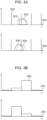
- Figs. 3 are explanatory diagrams for describing a situation where a deviation is generated in observed values in the same site of the subject by the displacement of the discretized positions between the images.
- graphic representations 3000 and 3040 represent appearing manners of the captured signal in a case where a capturing position of the subject is displaced in an opposite direction with respect to each of the modalities, in which the vertical axis indicates a signal value when the subject is captured by the modality, and the horizontal axis indicates a position in an x-axis direction.
- 3020 and 3060 denote signals obtained by capturing the same subject
- 3010 and 3050 represented by dotted lines indicate the same position on an x axis.
- a graphic representation 3070 represents the information of the pixel generated by discretizing the signal 3020 of Fig. 3A , in which the vertical axis indicates a density value, and the horizontal axis indicates a position in the x-axis direction.
- a pixel 3080 in Fig. 3B is a pixel generated from an area where a large number of the signals 3020 are included and represents that the density value is high.
- a graphic representation 3090 represents the information of the pixel generated by discretizing the signal 3060, in which the vertical axis indicates the density value, and the horizontal axis indicates the position in the x-axis direction.
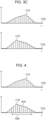
- graphic representations 3100 and 3120 respectively represent density values and positions of the pixels in which the resolution conversion of the pixels represented by the graphic representation 3070 and the graphic representation 3090 in Fig. 3B is performed. That is, the graphic representations 3070 and 3090 can be regarded as the signal values of the first image and the second image, and the graphic representations 3100 and 3120 can be regarded as the signal values of the first converted image and the second converted image.
- pixels 3110 and 3130 are respectively pixels where the signals 3020 and 3060 of the subject are most reflected.
- the one-dimensional graphic representation in only the x-axis direction is used to simplify the illustration in the drawing, but in the actual three-dimensional image, since the discretized position is displaced in each of the x, y, and z-axis directions in some cases, the search area size is calculated on the basis of the pixel size in each of the axis directions. It should be noted that, since the in-slice resolution (pixel sizes in the x and y-axis directions) in the general CT image is sufficient in many cases, a configuration may be adopted in which the noise reduction is not performed with regard to the x and y-axis directions.
- the search area sizes in the x and y-axis directions may be set as 0, and only the search area size in the z-axis direction may be calculated by the above-described method.
- the search area sizes in the x and y-axis directions may be set as a predetermined fixed value (for example, 1 mm), and only the search area size in the z-axis direction may be calculated by the above-described method. According to this, it is possible to accelerate the calculation.
- the positional displacement of the pixels by the displacement of the discretized positions is corrected, and the positions of the pixels representing the same site between the images are set to be closer to each other in some cases.
- the above-described predetermined constant may be decreased, and the search area size may be set to be smaller than the maximum value the displacement of the discretized positions. According to this, the search area size becomes smaller, and the difference in the excessive range is not calculated, so that a processing speed and an accuracy can be improved.
- the positional displacement of the pixels by the displacement of the discretized positions is not necessarily decreased.
- an alignment accuracy in the surrounding of the feature points between the images used for the alignment is high, and the alignment accuracy is lower as being away from the feature points.
- the positional displacement of the pixels between the images may be increased in some cases while an alignment error is added to the displacement of the discretized positions.
- the above-described predetermined constant may be changed for each position on the image. For example, the above-described predetermined constant may be decreased in the position in the surrounding of the feature point on the image, and the above-described predetermined constant may be increased in the position away from the feature point.
- step S2040 the position obtaining unit 1050 obtains the position of interest on the first converted image (position of interest on the reference image) and obtains the correspondence position on the second converted image corresponding to the position of interest by using the deformation information obtained in step S2020. Then, the obtained positions are output to the search area obtaining unit 1060 and the difference calculation unit 1070.
- Fig. 4 is an explanatory diagram for describing the search area set on the converted image.
- the graphic representations 3100 and 3120 respectively represent the same graphic representations as the graphic representations 3100 and 3120 in Fig. 3C .
- an example of a case will be illustrated where the pixel sizes in the x-axis direction in the first image and the second image are both 5 mm, and up-sampling is performed such that the pixel sizes become 1 mm.
- the search area size in the x-axis direction is the sum of half of the pixel size of each of the first image and the second image.
- the search area is a rectangular search area made up of the search area size calculated on the basis of the pixel size in each of the x, y, and z-axis directions.
- the difference calculation unit 1070 calculates the difference between the density value of the position of interest on the reference image and the density value of each of a plurality of positions in the search area on the second converted image. Then, the difference is output to the difference image generation unit 1080.
- distribution information of the density values in the search area on the second converted image may be calculated, and the difference value may be obtained by the comparison between the distribution information and the density value of the position of interest on the first converted image.
- the maximum value and the minimum value of the density values may be obtained as a density range of the density values in the search area, and the difference value may be obtained by the comparison with the density value of the position of interest on the first converted image.
- 0 when the density value of the position of interest is in between the maximum value and the minimum value of the density values in the search area, 0 may be set as the difference value assigned to the difference image.
- a difference value with the maximum value may be set as the difference value assigned to the difference image.
- the difference of the position of interest may be erroneously set as 0 in some cases. For this reason, the difference may be set as 0 in only a position where the density value of the position of interest is in between the maximum value and the minimum value of the density values in the search area and also the differences between the density value of the position of interest and the maximum value and the minimum value are lower than or equal to a threshold.
- the positions where the calculation of the difference value is to be performed may be part of positions on the first converted image previously extracted by the related-art image processing technology instead of all the positions on the first converted image. According to this, it is possible to reduce the processing time necessary for the noise reduction.
- the technique for setting the search area having the size determined on the basis of the pixel size in the surrounding of the pixel and using the density value in the area is used for the noise reduction at the time of the difference image generation.
- this method can also be used in other situations where the comparison between the pixels of interest is performed.
- the deformation information obtaining unit 1030 obtains the degree of image similarity by using the related-art image processing technique, but this method can also be used in the processing for obtaining the degree of image similarity for the image alignment.
- step S2070 all the positions (all the pixels) on the first converted image or part of the positions previously extracted by the related-art image processing technology are used, but the user may specify the positions. That is, the generation processing for the difference image in which the noise is reduced may be performed while all the positions in the area previously specified by the user or part of the positions are set as the target.
- only the second difference image may be generated and displayed, and the processing in steps S2040 to S2080 may be applied in only the neighboring area of the position of interest which is interactively specified by the user to replace only the neighboring area with the first difference image to be displayed. According to this, when the noise in only the necessary minimum position is reduced, the time necessary for the noise reduction can be made. Furthermore, since it is possible to exclude the position where the user determines that it is not the noise from the target of the noise reduction processing, it is possible to prevent the excessive signal deletion.
- the image processing apparatus is an apparatus that generates a three-dimensional difference image between the first image and the second image similarly as in the first embodiment. It is a feature that the image processing apparatus according to the present embodiment determines whether or not the noise reduction processing is to be executed in accordance with the pixel size of the input image and generates a three-dimensional difference image in accordance with the determined method.
- the image processing apparatus calculates the search area size on the basis of the pixel sizes of the first image and the second image similarly as in the first embodiment. At this time, in a case where the pixel sizes of the first image and the second image are lower than a predetermined threshold, it is determined that the displacement of the discretized positions is small, and the difference image is generated without implementing the noise reduction processing.
- the difference image in which the noise reduction processing has been implemented is generated similarly as in the first embodiment. According to this, in a case where the displacement of the discretized positions is small, it is possible to suppress the excessive deletion of the difference in the density values between the images. In addition, the processing time necessary for the noise reduction can be shortened.
- a configuration and processing according to the present embodiment will be described by using Fig. 1 and Fig. 5 .
- the search area size calculation unit 1040 determines whether or not the noise reduction processing is to be implemented on the basis of the pixel sizes of the first image and the second image. In addition, similarly as in the first embodiment, the calculation of the search area size is performed on the basis of the pixel sizes of the first image and the second image. In a case where the noise reduction processing is not to be implemented, the difference calculation unit 1070 calculates the difference value between the density value of the position of interest on the first converted image and the density value of the correspondence position on the second converted image as the difference value in the position of interest. On the other hand, in a case where the noise reduction processing is to be implemented, processing similar to the first embodiment is performed.
- Fig. 5 illustrates a flow chart of the overall processing procedure performed by the image processing apparatus 100.
- steps S5000 to S5020 and S5030 to S5090 since the processes respectively similar to step S2000 to S2020 and S2030 to S2090 according to the first embodiment are performed, the descriptions thereof will be omitted.
- steps S5000 to S5020 and S5030 to S5090 since the processes respectively similar to step S2000 to S2020 and S2030 to S2090 according to the first embodiment are performed, the descriptions thereof will be omitted.
- Fig. 2 Only a different part from the flow chart in Fig. 2 will be described.
- step S5025 the search area size calculation unit 1040 determines whether or not the noise reduction processing is to be implemented on the basis of the pixel sizes of the first image and the second image.
- step S5100 in a case where the pixel sizes of both the first image and the second image are lower than a predetermined threshold, it is determined that the displacement of the discretized positions is small to determine that the noise reduction is not necessary to be implemented, and the processing proceeds to step S5100.
- the processing proceeds to step S5030, and the noise reduction processing similar to the first embodiment is implemented. For example, a value in accordance with a lesion size or resolution power of the modality or a value previously decided by the user is set as the threshold.
- the noise reduction processing is to be implemented on the basis of the pixel size of each of the first image and the second image, but the determination may be performed on the basis of the sum of the pixel size of each of the first image and the second image.
- the predetermined threshold may be a different value in each of the x, y, and z-axis directions of the image.
- the determination on whether to perform the noise reduction or not may be performed for each axis to control whether to implement the noise reduction processing or not for each axis.
- step S5100 in a case where it is determined that the noise reduction is not necessary in all the three axis directions, and the processing proceeds to step S5030 in other cases.
- step S5100 the difference calculation unit 1070 calculates the difference value of the density values (second difference value according to the first embodiment) in the corresponding position between the first converted image and the second converted image. At this time, the corresponding position between the images is obtained by using the deformation information similarly as in step 55040.
- the determination on whether to perform the noise reduction processing or not is performed in accordance with the pixel size, in a case where the pixel size of the input image is sufficiently small and the noise based on the discretization is small, the unnecessary calculation can be omitted.
- an advantage is attained that the excessive deletion of the original difference value is prevented.
- the image processing apparatus is an apparatus that generates a three-dimensional difference image between the first image and the second image similarly as in the first embodiment. It is a feature that the image processing apparatus according to the present embodiment generates the three-dimensional difference image in which the noise is reduced by using a deformed search area where the search area is projected onto a deformed image in which deformation alignment is performed such that the same sites between the images are substantially matched with each other. Similarly as in the first embodiment, the image processing apparatus according to the present embodiment obtains the first converted image and the second converted image in which each of the first image and the second image are converted such that the resolutions are different from the original image and sets the search area in the surrounding of the correspondence position on the second converted image corresponding to the position of interest on the first converted image.
- the deformation alignment of the second converted image is performed such that the density values of the respective pixels become similar to those of the first converted image and projects the search area onto the obtained second deformed converted image by using the deformation information.
- the difference of the position of interest is calculated on the basis of the density value of the position of interest on the first converted image and the density values of the plurality of pixels in the deformed search area set in the surrounding of the correspondence position on a second deformed converted image, and the three-dimensional difference image in which the value is set as the density value of the position of interest on the three-dimensional difference image is generated.
- the deformed image of the second image in which the position of the same site on the image is substantially matched with the first image and the difference image can be obtained, when these images are arranged to be displayed, the user can easily check the density value in which positions on the first image and the deformed image the difference value on the difference image is calculated from.
- a configuration and processing according to the present embodiment will be described by using Fig. 6 and Fig. 7 .
- Fig. 6 illustrates a configuration of the image diagnosis system according to the present embodiment.
- An image processing apparatus 600 is constituted by the following components. Since the data obtaining unit 1010, the converted image obtaining unit 1020, the deformation information obtaining unit 1030, the search area size calculation unit 1040, the position obtaining unit 1050, the search area setting unit 1060, and the display control unit 1090 are the same functions as the first embodiment, the descriptions thereof will be omitted.
- a deformed image obtaining unit 1610 obtains a second deformed converted image in which the second converted image is deformed by using the deformation information obtained by the deformation information obtaining unit 1030.
- a search area projection unit 1620 obtains the deformed search area by projecting the search area set on the second converted image by the search area setting unit 1060 onto the second deformed converted image by using the deformation information obtained by the deformation information obtaining unit 1030.
- the difference calculation unit 1070 calculates the difference value in the position of interest on the basis of the density value of the pixel of interest on the first converted image and the density values of the plurality of pixels in the deformed search area on the second deformed converted image.
- Fig. 7 illustrates a flow chart of the overall processing procedure performed by the image processing apparatus 600.
- steps S7000 to S7050 and S7070 to S7090 since the processes respectively similar to step S2000 to S2050 and S2070 to 2090 according to the first embodiment are performed, the descriptions thereof will be omitted.
- steps S7000 to S7050 and S7070 to S7090 since the processes respectively similar to step S2000 to S2050 and S2070 to 2090 according to the first embodiment are performed, the descriptions thereof will be omitted.
- Fig. 2 Only a different part from the flow chart in Fig. 2 will be described.
- step S7052 the deformed image obtaining unit 1610 obtains the second deformed converted image in which the second converted image is deformed by using the deformation information obtained in step S7020. Then, the obtained second deformed converted image is output to the search area projection unit 1720 and the difference calculation unit 1070.
- step S7054 the search area projection unit 1620 projects the search area set on the second converted image in step S7050 onto the second deformed converted image as the deformed search area by using the deformation information obtained in step S7020. Then, the image is output to the difference calculation unit 1070.
- the search area on the second converted image to be projected may be the entire area in the search area or may also be a plurality of positions sampled from the search area.
- an entire internal area of a contour of the search area projected onto the second deformed converted image by using the deformation information can be set as the deformed search area.
- step S7060 the difference calculation unit 1080 obtains the difference value assigned to the difference image on the basis of the density value of the position of interest on the first converted image which is obtained in step S7060 and the density value of each of the pixels in the deformed search area on the second deformed converted image which is projected in step S7054.
- a difference from the process in step S2060 according to the first embodiment is only that the second converted image is changed to the second deformed converted image and the search area is changed to the deformed search area, and the other processes are similar.
- the present embodiment it is possible to perform the observation while the same sites between the deformed image of the second image in which the position of the same site on the image is substantially matched with the first image and the difference image in which the noise is reduced are easily compared with each other. For this reason, as compared with the first embodiment, an advantage is attained that the user can easily determine whether or not the difference value on the difference image is a difference based on the lesion.
- the degree of image similarity may be obtained on the basis of the difference value in which the noise caused by the displacement of the discretized positions is reduced when the degree of image similarity is calculated.
- the minimum value of the differences between the density value of the position of interest on the first converted image and each of the density values in the deformed search area on the second deformed converted image is used. According to this, the degree of image similarity in which the displacement of the discretized positions is taken into account can be obtained, and as a result, it is possible to obtain the difference image in which the noise is further reduced.
- the image processing apparatus is an apparatus that generates the difference image between the three-dimensional images similarly as in the first embodiment. It is a feature that the image processing apparatus according to the present embodiment sets the search area in both the position of interest on the first converted image and the correspondence position on the second converted image and obtains the difference value in the position of interest on the basis of the density values of the pixels in each of the search areas.
- a direction in which the search area is set on the second converted image to obtain the difference with the position of interest on the first converted image is set as a forward direction.
- a direction in which the search area is set on the first converted image to obtain the difference with the correspondence position on the second converted image is set as a backward direction.
- the image processing apparatus obtains the difference value in the position of interest on the difference image in each of the forward direction and the backward direction and sets a representative difference value in which the two difference values are integrated with each other as the density value of the difference image to be generated. According to this, the signal that cannot be captured by the calculation in only one of the directions can be kept in the difference image.
- a configuration and processing according to the present embodiment will be described by using Fig. 1 and Fig. 8 .
- a configuration of the image processing apparatus according to the present embodiment is similar to that of the first embodiment. However, since the search area setting unit 1060 and the difference calculation unit 1070 have different functions from the first embodiment, the functions will be described below. Since the functions of the other configurations are the same as the first embodiment, the descriptions thereof will be omitted.
- the search area setting unit 1060 sets the search area made up of the search area size in each of the surrounding of the position of interest on the first converted image and the surrounding of the correspondence position on the second converted image.
- the difference calculation unit 1070 calculates the difference value in the forward direction and each difference value in the backward direction and obtains the representative difference value in which the two difference values are integrated with each other.
- Fig. 8 illustrates a flow chart of the overall processing procedure performed by the image processing apparatus 100.
- steps S8000 to S8040 and S8070 to S8090 since the processes respectively similar to steps S2000 to S2040 and S2070 to S2090 according to the first embodiment are performed, the descriptions thereof will be omitted.
- steps S8000 to S8040 and S8070 to S8090 since the processes respectively similar to steps S2000 to S2040 and S2070 to S2090 according to the first embodiment are performed, the descriptions thereof will be omitted.
- Fig. 2 Only a different part from the flow chart in Fig. 2 will be described.
- step S8050 the search area setting unit 1060 sets a first search area made up of the search area size calculated in step S8030 in the surrounding while the position of interest on the first converted image is set as the center.
- a second search area made up of the search area size calculated in step S8030 is set in the surrounding while the correspondence position on the second converted image is set as the center. Then, information of the set first search area and second search area is output to the difference calculation unit 1070.
- step S8060 the difference calculation unit 1070 calculates the difference value (in the forward direction) in the position of interest on the basis of the density value of the position of interest on the first converted image and the density value of each of the pixels in the second search area on the second converted image similarly as in step S2060 according to the first embodiment. Furthermore, the difference calculation unit 1070 calculates the difference value (in the backward direction) in the position of interest on the basis of the density value of the correspondence position on the second converted image and the density value of each of the pixels in the first search area on the first converted image.
- This processing can be performed similarly as in step S2060 according to the first embodiment since only the position of interest and the correspondence position are swapped. It should be noted that various methods described in step S2060 can be used for the calculation of the difference value.
- step S8065 the difference calculation unit 1070 integrates the difference value in the forward direction and the difference value in the backward direction which are calculated in step S8060 to each other to calculate the representative difference value. For example, absolute values of both are compared with each other, and the difference value having the higher absolute value is obtained as the representative difference value. Then, the obtained representative difference value is output to the difference image generation unit 1080 as the density value in the position of interest of the difference image.
- the difference value is captured in one of the forward direction and the backward direction, and the difference value cannot be captured in the other direction in some cases.
- the signal may disappear in the difference value on one direction in some cases, but when the representative difference value is calculated by using the bidirectional difference values, the above-described difference value can be kept on the difference image.
- the difference value having the higher absolute value is set as the representative difference value, but the difference value having the lower absolute value may be set as the representative difference value.
- an average value of the difference value in the forward direction and the difference value in the backward direction may be set as the representative difference value. According to this, while the difference value with the signal that exists in only one of the images is decreased, the signal of the noise can be further suppressed.
- the size of the search area does not necessarily need to be adaptively decided on the basis of the pixel size of the input image. That is, the preferable search area size with respect to the typical pixel size may be previously set as a default to be used. In this case, the search area size calculation unit 1040 and the processing in step S8030 become unnecessary.
- an advantage is attained that a risk of deleting the signal of the lesion having the small size which only exists in one of the images can be abbreviated as compared with the first embodiment.
- the image processing apparatus is an apparatus that generates a three-dimensional difference image between the plurality of three-dimensional image (the first image and the second image) similarly as in the first embodiment.
- the present invention is implemented by a still simpler configuration.
- a configuration and the processing according to the present embodiment will be described by using Fig. 9 and Fig. 10 .
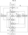
- Fig. 9 illustrates a configuration of the image diagnosis system according to the present embodiment. Since the data server 110 and the display unit 120 have the same functions as the first embodiment, the descriptions thereof will be omitted.
- An image processing apparatus 900 is constituted by the following components. Since the data obtaining unit 1010, the search area calculation unit 1040, the difference image generation unit 1080, and the display control unit 1090 have the same functions as the first embodiment, the descriptions thereof will be omitted. With regard to the other configurations, functions thereof will be described below.
- the deformation information obtaining unit 1030 obtains the deformation information representing the correspondence relationship of the positions on the images between the first image and the second image.
- the position obtaining unit 1050 obtains the position of interest on the first image and obtains the correspondence position on the second image corresponding to the position of interest on the first image by using the deformation information obtained by the deformation information obtaining unit 1030.
- the search area setting unit 1060 sets the search area made up of the search area size in the surrounding of the correspondence position on the second image.
- the difference calculation unit 1070 calculates the difference value in the position of interest on the basis of the density value of the pixel of interest on the first image and the density values of the plurality of pixels in the search area on the second image.
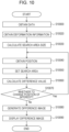
- Fig. 10 illustrates a flow chart of the overall processing procedure performed by the image processing apparatus 900.
- step S10090 since the processing similar to step S2090 according to the first embodiment is performed, the descriptions thereof will be omitted.
- step S10090 since the processing similar to step S2090 according to the first embodiment is performed, the descriptions thereof will be omitted.
- Fig. 2 Only a different part from the flow chart in Fig. 2 will be described.
- step S10000 the data obtaining unit 1010 obtains the first image and the second image input to the image processing apparatus 900. Then, the obtained first image and second image are output to the deformation information obtaining unit 1030, the position obtaining unit 1050, the search area setting unit 1060, and the difference calculation unit 1070. In addition, the information related to the pixel sizes of the first image and the second image is output to the search area size calculation unit 1040.
- step S10020 the deformation information obtaining unit 1030 obtains the deformation information such that the pixels representing the same site are substantially matched with each other between the first image and the second image. That is, the alignment processing between (deformation estimating processing) between the first image and the second image is performed. Then, the obtained deformation information is output to the position obtaining unit 1050.
- the deformation information can be obtained by the related-art image processing technique similarly as in the first embodiment.
- step S10030 the search area size calculation unit 1040 calculates the search area size used for the calculation of the difference value on the basis of the pixel size of the first image and the pixel size of the second image. Then, the calculated search area size is output to the search area setting unit 1060.
- the nature that the positions of the pixels where the original imaging signal of the subject is most reflected are displaced by the sum of half of the pixel size of each of the original images at maximum by the displacement of the discretized positions at the time of the image generation between the first image and the second image is used. That is, the sum of half of the pixel size of each of the first image and the second image is calculated as the search area size.
- step S10050 the search area setting unit 1060 sets the search area made up of the search area size calculated in step S10030 in the surrounding while the correspondence position on the second image is set as the center. Then, the information of the set search area is output to the difference calculation unit 1070.
- step S10060 the difference calculation unit 1070 obtains the difference value assigned to the difference image on the basis of the density values of the positions of interest on the first image and the density value in each of the plurality of positions in the search area on the second image which are obtained in step S10040. Then, the difference value is output to the difference image generation unit 1080.
- the difference value is calculated from the density values of the reference image (the first image or the first converted image) and the second converted image, but, according to the present embodiment, the difference value is calculated from the density values of the first image and the second image similarly as in step S2060 according to the first embodiment. That is, a difference between the density value of the positions of interest on the first image and the density value of each of the plurality of positions in the search area on the second image is calculated, and the minimum value among those is obtained as the difference value assigned to the difference image.
- the density value may be obtained from each of the pixels while the positions of all the pixels in the search area are set as the plurality of positions.
- measurement points at a predetermined interval smaller than a pixel pitch may be set in the search area to obtain the density value in each of the measurement points from the density value the neighboring pixel by performing an interpolation.
- step S10070 the position obtaining unit 1050 determines whether or not the difference values in all the positions (all the pixels) on the first image are calculated. In a case where the difference values in all the positions are calculated, the processing proceeds to step S10080. On the other hand, in a case where the difference values in all the positions are not obtained, the processing returns to step S10040.
- the calculation of the difference value may be performed in part of the positions on the first image which are previously extracted by the related-art image processing technology instead of all the positions on the first image. According to this, it is possible to reduce the processing time necessary for the noise reduction.
- step S10080 the difference image generation unit 1080 generates the difference image (first difference image) in which the difference value in each of the positions (pixels) on the first image is set as the density value. Then, the obtained difference image is saved in the data server 110. In addition, the obtained difference image is output to the display control unit 1090.
- the general difference image (second difference image) in which the second difference value (difference between the density value of the position of interest on the first image and the density value of the correspondence position on the second image) which is calculated in step S10060 is set as the density value may also be generated as well.
- an advantage similar to the first embodiment can be attained without obtaining the first converted image and the second converted image. That is, when the difference value is calculated from the search area having the necessary minimum size in which the displacement of the discretized positions is taken into account, the user can examine the difference image in which the necessary signal on the difference image is kept and also the noise generated from the difference in the density values due to the displacement of the discretized positions between the images is reduced. It should be noted that, with regard to each of the second to fifth embodiments too, the implementation can be performed without obtaining the first converted image and the second converted image similarly as in the present embodiment.
- the image processing apparatus is an apparatus that generates a three-dimensional difference image between the first image and the second image similarly as in the first embodiment. It should be noted however that it is a feature that, in a case where the pixel sizes between the images are different from each other, the image processing apparatus according to the present embodiment generates the difference image having the reduced noise which is derived from the difference in the density values between the images which is generated when the pixel sizes are different from each other.
- the image processing apparatus according to the present embodiment will be described.
- a signal data weighted average value in a predetermined section for example, an in-plane pixel size or a slice thickness of a slice image
- the density value of the pixel having the large pixel size is calculated while the signal data in a wider range is smoothed as compared with the small pixel.
- the image processing apparatus approximately regards the density value of the second image as the signal data.
- the density value of the pixel in the area on the second image having the same size as the single pixel of the first image is smoothed
- the density value generated from the signal data of the area having the same size as the single pixel of the first image is approximately obtained, and a second smoothed image in which the second image is smoothed is generated.
- the processing for generating the difference image which is similar to the first embodiment is performed by using the generated second smoothed image instead of the second image. According to this, since the smoothing area on the second image where the difference in the density value with the pixel of interest on the first image becomes the lowest is selected, and the change in the density value caused by a minute displacement of the area to be smoothed can be absorbed.
- the processing for generating the difference image which is similar to the first embodiment is performed by using a first smoothed image obtained by smoothing the first image instead of the first image.
- the two images having the different pixel sizes are set as the inputs, the user can observe the difference image having the reduced noise as compared with the first embodiment.
- a configuration and processing according to the present embodiment will be described by using Fig. 11 and Fig. 12 .
- Fig. 11 illustrates a configuration of the image diagnosis system according to the present embodiment.
- a smoothed image obtaining unit 11010 With regard to a smoothed image obtaining unit 11010, a function thereof will be described below. Since the other configurations have the same functions as the first embodiment, the descriptions thereof will be omitted.
- the smoothed image obtaining unit 11010 obtains the second smoothed image in which the second image is smoothed.
- the smoothed image obtaining unit 11010 obtains the first smoothed image in which the first image is smoothed.
- Fig. 12 illustrates a flow chart of the overall processing procedure performed by an image processing apparatus 1100.
- steps S12030 to S12100 since the processes in steps S2020 to S2090 according to the first embodiment are respectively performed, the descriptions thereof will be omitted.
- steps S2020 to S2090 according to the first embodiment since the processes in steps S2020 to S2090 according to the first embodiment are respectively performed, the descriptions thereof will be omitted.
- Fig. 2 Only a different part from the flow chart in Fig. 2 will be described.
- step S10000 the data obtaining unit 1010 obtains the first image and the second image to be input to the image processing apparatus 1100. Then, the obtained first image and second image are output to a smoothed image obtaining unit 1910. In addition, the information related to the pixel sizes of the first image and the second image is output to the search area size calculation unit 1040.
- step S12010 in a case where the pixel size of the second image is smaller than that of the first image, the smoothed image obtaining unit 1910 obtains the second smoothed image in which the second image is smoothed. Then, the obtained second smoothed image and first image are output to the converted image obtaining unit 1020. In this case, the image processing apparatus 1100 performs the subsequent processing by replacing the second image with the second smoothed image.
- the first smoothed image in which the first image is smoothed is obtained. Then, the obtained first smoothed image and second image are output to the converted image obtaining unit 1020. In this case, the image processing apparatus 1100 performs the subsequent processing by replacing the first image with the first smoothed image.
- the smoothed image obtaining unit 1910 smooths the small pixel image by using a kernel having the same size as the pixel size of the large pixel image. For example, a case is supposed where the respective pixel sizes in the x, y, and z-axis directions of the large pixel image are 1.5 mm, 1.5 mm, and 5 mm, and the respective pixel sizes of the small pixel image are 0.5 mm, 0.5 mm, and 1 mm.
- the kernel sizes corresponds to 1.5 mm ⁇ 1.5 mm ⁇ 5 mm, and this is the size corresponding to 3 ⁇ 3 ⁇ 5 pixels on the small pixel image.
- Related-art smoothing processing is performed by using this kernel.
- processing for evenly averaging the density values for 3 ⁇ 3 ⁇ 5 pixels may be performed, or processing for calculating a weighted average as in the smoothing processing by a Gaussian filter may also be performed.
- the kernel sizes in the x and y-axis directions may be set as 1 pixel, and only the density value in the z-axis direction may be smoothed.
- a ratio of the pixel sizes between the images is an odd-numbered multiple. That is, the kernel sizes in the respective axis directions on the small pixel image are set as the odd-numbered pixels.
- the ratio of the pixel sizes between the images is an even-numbered multiple.
- the kernel size corresponds to 1 ⁇ 1 ⁇ 4 pixels on the small pixel image.
- the processing is performed while the kernel sizes in the axis directions are set as the odd-numbered pixels, and the pixel of the filter processing target and the pixels in the positive and negative directions of the axis while the pixel is set as the center are used evenly (2 pixels each in the case of 5 pixels).
- the kernel size is even-numbered pixels like 4 pixels, the pixels in the positive and negative directions of the axis cannot be evenly used. For this reason, the image in which the resolution of the small pixel image is converted is generated such that the pixel size of the large pixel image becomes the odd-numbered multiple with respect to the small pixel image.
- the pixel size of the small pixel image is converted such that the pixel size of the large pixel image becomes the odd-numbered multiple with respect to the image in which the resolution of the small pixel image is converted and to also have the closest value lower than or equal to the pixel size of the original small pixel image.
- the pixel size in only the z-axis direction is the even-numbered multiple, the resolution in only the z direction is converted.
- the kernel size on the image in which the resolution is converted corresponds to 1 ⁇ 1 ⁇ 5 pixels, and it is possible to smooth the density value by using evenly the pixels in the positive and negative directions of the axis.
- the density value of the small pixel image is approximately regarded as the signal data, and the density value of the smoothed image is calculated from the approximated signal data.
- a method of calculating the density value from the signal data is preferably similar to the method of actually generating the density value of the large pixel image from the signal data to reconstruct the image. That is, in a case where a reconstruction algorithm for the large pixel image is already established, the density value of the smoothed image may be calculated in accordance with the algorithm.
- the first image and the second image are output to the converted image obtaining unit 1020, and the present step may be omitted.
- the processing similar to the first embodiment is implemented.
- step S12020 similarly as in the first embodiment, the converted image obtaining unit 1020 obtains the first converted image in which the resolution of the first image (or the first smoothed image) is converted and the second converted image in which the resolution of the second image (or the second smoothed image) is converted such that the pixel sizes between the two images becomes the same. Then, the generated converted images are output to the deformation information obtaining unit 1030, the position obtaining unit 1050, the search area setting unit 1060, and the difference calculation unit 1070.
- the user when the smoothing processing is performed such that the image having the smaller pixel size is approximated to the image having the larger pixel size between the images having the different pixel sizes and also the difference calculation is performed, the user can observe the difference image in which the noise generated from the difference in the pixel sizes as compared with the first embodiment.
- the smoothing processing is applied to the second image in a case where the pixel size of the second image is smaller than that of the first image, but a similar benefit can be attained even when the smoothing processing is applied to the second converted image.
- the smoothing processing may be applied to the first converted image instead of the first image.
- the kernel size for the smoothing may be decided on the basis of the pixel size of the original image instead of the pixel size of the converted image.
- the processing similar to the present embodiment also can be performed in the second embodiment to the fifth embodiment. That is, after the obtainment of the image data, the smoothed image is generated in which the image having the smaller pixel size among the first image and the second image is smoothed in accordance with the image having the larger pixel size, and the similar noise reduction effect can be attained by performing the subsequent processing by replacing the original image with the smoothed image.
- the smoothed image in which the smoothing processing is applied to the second deformed converted image may be generated and used by replacing the second deformed converted image.
- the first image and the second image (or the converted images) to which the smoothing is not applied may be used for the deformation information obtaining processing implemented by the deformation information obtaining unit, and the smoothed image (or the converted image) may be used for only the difference value calculation processing performed by the difference calculation unit.
- the deformation information is obtained by using the image after the smoothing processing, but as a configuration for obtaining the deformation information from the data server 110, the processing for obtaining the deformation information may be skipped. Then, the difference image between the first image or the first converted image and the second smoothed image may be generated by using the deformation information. For example, in a case where the user who observes the difference image generated by the image processing apparatus according to the first embodiment determines that the noise generated by the difference in the pixel sizes needs to be reduced, the image processing apparatus according to the present embodiment can generate the difference image in which the noise is reduced by using the already obtained deformation information. According to this, since the processing for obtaining the deformation information can be skipped, the processing can be accelerated.
- the image in which the resolution of the second image is converted is smoothed such that the pixel size of the first image becomes the odd-numbered multiple with respect to the second image, but the resolution does not necessarily need to be converted.
- the pixel as the smoothing target on the second image is set as the center
- a first area having the same pixel size of the first image is set, and the smoothing processing may be performed in accordance with the density values of the pixels included in the first area and a volume ratio of the pixels. More specifically, in a case where the pixels of the second image are completely included in the first area, a weighting coefficient related to the density values of the pixels is set as 1.
- a weighting coefficient related to the density values of the pixels is set as 0.5. Then, it is possible to obtain the second smoothed image in which a weighted average value of the density values of all the pixels included in the first area is set as the density value. According to this, an equivalent benefit can be attained even when the resolution of the second image is not converted such as that the pixel size of the first image becomes the odd-numbered multiple with respect to the second image.
- the present invention can adopt an embodiment as a system, an apparatus, a method, a program, or a recording medium (storage medium), for example.
- the present invention may be applied to a system constituted by a plurality of devices (such as, for example, a host computer, an interface device, an imaging apparatus, and a Web application) and may also be applied to an apparatus constituted by a single device.
- a recording medium storage medium
- a program code computer program
- the above-described storage medium is of course a computer-readable storage medium.
- a computer or a CPU or an MPU
- the program code itself read out from the recording medium realizes the functions of the above-described embodiments, and the recording medium that records the program code constitutes the present invention.
- the image processing apparatus characterized in that the search area size calculation means calculates the search area size on a basis of a sum of pixel sizes in respective axis directions of the first image and the second image.
- the image processing apparatus according to statement 1, further comprising:
- the image processing apparatus characterized in that the difference means decides a difference value corresponding to the position of interest on a basis of a difference value between the density value of the position of interest on the first image and each of the density values of the plurality of positions in the search area on the second image.
- the image processing apparatus characterized in that the difference means decides a difference value corresponding to the position of interest on a basis of the density value of the position of interest on the first image and a value calculated from the density values of the plurality of positions in the search area on the second image.
- the image processing apparatus characterized in that the distribution information of the density values is a density range of the density values in the search area on the second image.
- the image processing apparatus according to any one of statements 2 to 10, further comprising:
- the image processing apparatus characterized in that the smoothing means decides a parameter of the smoothing processing on a basis of a pixel size of at least one of the first image and the second image.
- a program characterized by causing a computer to execute the image processing method according to statement 13.
Landscapes
- Engineering & Computer Science (AREA)
- Health & Medical Sciences (AREA)
- Physics & Mathematics (AREA)
- Life Sciences & Earth Sciences (AREA)
- General Physics & Mathematics (AREA)
- Medical Informatics (AREA)
- Theoretical Computer Science (AREA)
- Nuclear Medicine, Radiotherapy & Molecular Imaging (AREA)
- Biomedical Technology (AREA)
- General Health & Medical Sciences (AREA)
- Molecular Biology (AREA)
- Computer Vision & Pattern Recognition (AREA)
- High Energy & Nuclear Physics (AREA)
- Surgery (AREA)
- Veterinary Medicine (AREA)
- Biophysics (AREA)
- Pathology (AREA)
- Radiology & Medical Imaging (AREA)
- Heart & Thoracic Surgery (AREA)
- Public Health (AREA)
- Animal Behavior & Ethology (AREA)
- Optics & Photonics (AREA)
- Spectroscopy & Molecular Physics (AREA)
- Multimedia (AREA)
- Image Processing (AREA)
- Apparatus For Radiation Diagnosis (AREA)
- Image Analysis (AREA)
Applications Claiming Priority (3)
| Application Number | Priority Date | Filing Date | Title |
|---|---|---|---|
| JP2016169609 | 2016-08-31 | ||
| PCT/JP2017/031194 WO2018043575A1 (ja) | 2016-08-31 | 2017-08-30 | 画像処理装置、画像処理方法およびプログラム |
| EP17846579.5A EP3508127B1 (de) | 2016-08-31 | 2017-08-30 | Bildverarbeitungsvorrichtung, bildverarbeitungsverfahren und programm |
Related Parent Applications (2)
| Application Number | Title | Priority Date | Filing Date |
|---|---|---|---|
| EP17846579.5A Division-Into EP3508127B1 (de) | 2016-08-31 | 2017-08-30 | Bildverarbeitungsvorrichtung, bildverarbeitungsverfahren und programm |
| EP17846579.5A Division EP3508127B1 (de) | 2016-08-31 | 2017-08-30 | Bildverarbeitungsvorrichtung, bildverarbeitungsverfahren und programm |
Publications (2)
| Publication Number | Publication Date |
|---|---|
| EP4465240A2 true EP4465240A2 (de) | 2024-11-20 |
| EP4465240A3 EP4465240A3 (de) | 2025-02-26 |
Family
ID=61301095
Family Applications (2)
| Application Number | Title | Priority Date | Filing Date |
|---|---|---|---|
| EP17846579.5A Active EP3508127B1 (de) | 2016-08-31 | 2017-08-30 | Bildverarbeitungsvorrichtung, bildverarbeitungsverfahren und programm |
| EP24197952.5A Pending EP4465240A3 (de) | 2016-08-31 | 2017-08-30 | Bildverarbeitungsvorrichtung, bildverarbeitungsverfahren und programm |
Family Applications Before (1)
| Application Number | Title | Priority Date | Filing Date |
|---|---|---|---|
| EP17846579.5A Active EP3508127B1 (de) | 2016-08-31 | 2017-08-30 | Bildverarbeitungsvorrichtung, bildverarbeitungsverfahren und programm |
Country Status (5)
| Country | Link |
|---|---|
| US (1) | US11468589B2 (de) |
| EP (2) | EP3508127B1 (de) |
| JP (1) | JP7023641B2 (de) |
| CN (1) | CN109715070B (de) |
| WO (1) | WO2018043575A1 (de) |
Families Citing this family (11)
| Publication number | Priority date | Publication date | Assignee | Title |
|---|---|---|---|---|
| JP7383371B2 (ja) * | 2018-02-28 | 2023-11-20 | キヤノン株式会社 | 画像処理装置 |
| JP2020025786A (ja) * | 2018-08-14 | 2020-02-20 | 富士フイルム株式会社 | 画像処理装置、方法及びプログラム |
| JP7277131B2 (ja) * | 2018-12-26 | 2023-05-18 | キヤノン株式会社 | 画像処理装置、画像処理方法、及びプログラム |
| JP7387280B2 (ja) | 2019-04-10 | 2023-11-28 | キヤノン株式会社 | 画像処理装置、画像処理方法及びプログラム |
| JP2020174861A (ja) * | 2019-04-17 | 2020-10-29 | キヤノン株式会社 | 情報処理装置、情報処理方法およびプログラム |
| CN110133556B (zh) * | 2019-05-29 | 2021-01-19 | 上海联影医疗科技股份有限公司 | 一种磁共振图像处理方法、装置、设备及存储介质 |
| JP7451098B2 (ja) * | 2019-06-26 | 2024-03-18 | キヤノン株式会社 | 画像処理装置、画像処理方法及びプログラム |
| JP7530184B2 (ja) * | 2020-02-20 | 2024-08-07 | キヤノン株式会社 | 画像処理装置、画像処理方法、画像処理システム及びプログラム |
| JP7777956B2 (ja) * | 2021-10-12 | 2025-12-01 | キヤノン株式会社 | 画像処理装置、画像処理方法及びプログラム |
| JP2023128704A (ja) | 2022-03-04 | 2023-09-14 | キヤノン株式会社 | 画像処理装置、方法、プログラム及び記憶媒体 |
| TWI846052B (zh) * | 2022-09-12 | 2024-06-21 | 長庚醫療財團法人林口長庚紀念醫院 | 利用人工智慧分析泌尿系統結石之方法及泌尿系統結石分析系統 |
Citations (1)
| Publication number | Priority date | Publication date | Assignee | Title |
|---|---|---|---|---|
| JP2016169609A (ja) | 2015-03-11 | 2016-09-23 | 本田技研工業株式会社 | 鞍乗型車両の排気マフラー装置 |
Family Cites Families (5)
| Publication number | Priority date | Publication date | Assignee | Title |
|---|---|---|---|---|
| US6738063B2 (en) * | 2002-02-07 | 2004-05-18 | Siemens Corporate Research, Inc. | Object-correspondence identification without full volume registration |
| JP4858085B2 (ja) * | 2006-10-25 | 2012-01-18 | ソニー株式会社 | 画像処理装置および画像処理方法、並びにプログラム |
| US20090074276A1 (en) * | 2007-09-19 | 2009-03-19 | The University Of Chicago | Voxel Matching Technique for Removal of Artifacts in Medical Subtraction Images |
| US8559746B2 (en) * | 2008-09-04 | 2013-10-15 | Silicon Image, Inc. | System, method, and apparatus for smoothing of edges in images to remove irregularities |
| US10032077B1 (en) * | 2015-10-29 | 2018-07-24 | National Technology & Engineering Solutions Of Sandia, Llc | Vehicle track identification in synthetic aperture radar images |
-
2017
- 2017-08-30 EP EP17846579.5A patent/EP3508127B1/de active Active
- 2017-08-30 WO PCT/JP2017/031194 patent/WO2018043575A1/ja not_active Ceased
- 2017-08-30 CN CN201780056800.7A patent/CN109715070B/zh active Active
- 2017-08-30 EP EP24197952.5A patent/EP4465240A3/de active Pending
- 2017-08-30 JP JP2017165126A patent/JP7023641B2/ja active Active
-
2019
- 2019-02-28 US US16/288,931 patent/US11468589B2/en active Active
Patent Citations (1)
| Publication number | Priority date | Publication date | Assignee | Title |
|---|---|---|---|---|
| JP2016169609A (ja) | 2015-03-11 | 2016-09-23 | 本田技研工業株式会社 | 鞍乗型車両の排気マフラー装置 |
Non-Patent Citations (1)
| Title |
|---|
| SHIGEHIKO KATSURAGAWAKUNIO DOI: "Development of a voxel-matching technique for substantial reduction of subtraction artifacts in temporal subtraction images obtained from thoracic MDCT.", JOURNAL OF DIGITAL IMAGING, vol. 23, no. 1, 2010, pages 31 - 38, XP019764529 |
Also Published As
| Publication number | Publication date |
|---|---|
| JP7023641B2 (ja) | 2022-02-22 |
| JP2018038815A (ja) | 2018-03-15 |
| WO2018043575A1 (ja) | 2018-03-08 |
| EP3508127A4 (de) | 2020-04-08 |
| EP3508127A1 (de) | 2019-07-10 |
| EP3508127B1 (de) | 2024-10-09 |
| US11468589B2 (en) | 2022-10-11 |
| EP4465240A3 (de) | 2025-02-26 |
| CN109715070B (zh) | 2023-05-05 |
| US20190197723A1 (en) | 2019-06-27 |
| CN109715070A (zh) | 2019-05-03 |
Similar Documents
| Publication | Publication Date | Title |
|---|---|---|
| EP3508127B1 (de) | Bildverarbeitungsvorrichtung, bildverarbeitungsverfahren und programm | |
| EP3447733B1 (de) | Selektive bildrekonstruktion | |
| EP3206189B1 (de) | Bildverarbeitungsvorrichtung, bildverarbeitungsverfahren und programm | |
| JP7635185B2 (ja) | 画像処理装置、画像診断システム、画像処理方法およびプログラム | |
| US10810717B2 (en) | Image processing apparatus, image processing method, and image processing system | |
| EP3355273A1 (de) | Grobausrichtungsdetektion in bilddaten | |
| JP6643827B2 (ja) | 画像処理装置、画像処理方法、及びプログラム | |
| US20120321161A1 (en) | Image processing apparatus, image processing method, image pickup system, and program | |
| CN105761217A (zh) | 图像重建方法及装置 | |
| US20190251691A1 (en) | Information processing apparatus and information processing method | |
| US12586167B2 (en) | Medical image processing apparatus and medical image processing method | |
| EP3662835B1 (de) | Bildverarbeitungsvorrichtung, bildverarbeitungsverfahren, bildverarbeitungssystem und programm | |
| US10453184B2 (en) | Image processing apparatus and X-ray diagnosis apparatus | |
| US20190374114A1 (en) | Blood flow analysis apparatus, blood flow analysis method, and blood flow analysis program | |
| JP7387280B2 (ja) | 画像処理装置、画像処理方法及びプログラム | |
| JP2023019113A (ja) | 画像処理装置、画像処理方法およびプログラム | |
| JP2018022334A (ja) | 画像処理装置および画像処理方法 | |
| JP2023080703A (ja) | 医用画像処理装置、方法及びプログラム | |
| Walvoord et al. | Localization of fiducial skin markers in MR images using correlation pattern recognition for PET/MRI nonrigid breast image registration | |
| CN108257088A (zh) | 斜率约束三次插值 |
Legal Events
| Date | Code | Title | Description |
|---|---|---|---|
| PUAI | Public reference made under article 153(3) epc to a published international application that has entered the european phase |
Free format text: ORIGINAL CODE: 0009012 |
|
| STAA | Information on the status of an ep patent application or granted ep patent |
Free format text: STATUS: THE APPLICATION HAS BEEN PUBLISHED |
|
| AC | Divisional application: reference to earlier application |
Ref document number: 3508127 Country of ref document: EP Kind code of ref document: P |
|
| AK | Designated contracting states |
Kind code of ref document: A2 Designated state(s): AL AT BE BG CH CY CZ DE DK EE ES FI FR GB GR HR HU IE IS IT LI LT LU LV MC MK MT NL NO PL PT RO RS SE SI SK SM TR |
|
| RIN1 | Information on inventor provided before grant (corrected) |
Inventor name: ISHIKAWA, RYO Inventor name: SATOH, KIYOHIDE Inventor name: TANAKA, TORU |
|
| REG | Reference to a national code |
Ref country code: DE Ref legal event code: R079 Free format text: PREVIOUS MAIN CLASS: G06T0007254000 Ipc: A61B0006030000 |
|
| PUAL | Search report despatched |
Free format text: ORIGINAL CODE: 0009013 |
|
| AK | Designated contracting states |
Kind code of ref document: A3 Designated state(s): AL AT BE BG CH CY CZ DE DK EE ES FI FR GB GR HR HU IE IS IT LI LT LU LV MC MK MT NL NO PL PT RO RS SE SI SK SM TR |
|
| RIC1 | Information provided on ipc code assigned before grant |
Ipc: G06T 7/254 20170101ALI20250120BHEP Ipc: G06T 7/00 20170101ALI20250120BHEP Ipc: G06T 5/50 20060101ALI20250120BHEP Ipc: G06T 1/00 20060101ALI20250120BHEP Ipc: G01T 1/161 20060101ALI20250120BHEP Ipc: A61B 8/14 20060101ALI20250120BHEP Ipc: A61B 5/055 20060101ALI20250120BHEP Ipc: A61B 6/03 20060101AFI20250120BHEP |
|
| STAA | Information on the status of an ep patent application or granted ep patent |
Free format text: STATUS: REQUEST FOR EXAMINATION WAS MADE |
|
| 17P | Request for examination filed |
Effective date: 20250826 |
|
| GRAP | Despatch of communication of intention to grant a patent |
Free format text: ORIGINAL CODE: EPIDOSNIGR1 |
|
| STAA | Information on the status of an ep patent application or granted ep patent |
Free format text: STATUS: GRANT OF PATENT IS INTENDED |
|
| INTG | Intention to grant announced |
Effective date: 20260126 |
|
| GRAS | Grant fee paid |
Free format text: ORIGINAL CODE: EPIDOSNIGR3 |