EP4464889A2 - Rotorblatt einer windenergieanlage - Google Patents
Rotorblatt einer windenergieanlage Download PDFInfo
- Publication number
- EP4464889A2 EP4464889A2 EP24198302.2A EP24198302A EP4464889A2 EP 4464889 A2 EP4464889 A2 EP 4464889A2 EP 24198302 A EP24198302 A EP 24198302A EP 4464889 A2 EP4464889 A2 EP 4464889A2
- Authority
- EP
- European Patent Office
- Prior art keywords
- rotor blade
- profile
- thickness
- separation point
- trailing edge
- Prior art date
- Legal status (The legal status is an assumption and is not a legal conclusion. Google has not performed a legal analysis and makes no representation as to the accuracy of the status listed.)
- Pending
Links
Images


Classifications
-
- F—MECHANICAL ENGINEERING; LIGHTING; HEATING; WEAPONS; BLASTING
- F03—MACHINES OR ENGINES FOR LIQUIDS; WIND, SPRING, OR WEIGHT MOTORS; PRODUCING MECHANICAL POWER OR A REACTIVE PROPULSIVE THRUST, NOT OTHERWISE PROVIDED FOR
- F03D—WIND MOTORS
- F03D1/00—Wind motors with rotation axis substantially parallel to the air flow entering the rotor
- F03D1/06—Rotors
- F03D1/0608—Rotors characterised by their aerodynamic shape
- F03D1/0633—Rotors characterised by their aerodynamic shape of the blades
- F03D1/0641—Rotors characterised by their aerodynamic shape of the blades of the section profile of the blades, i.e. aerofoil profile
-
- F—MECHANICAL ENGINEERING; LIGHTING; HEATING; WEAPONS; BLASTING
- F03—MACHINES OR ENGINES FOR LIQUIDS; WIND, SPRING, OR WEIGHT MOTORS; PRODUCING MECHANICAL POWER OR A REACTIVE PROPULSIVE THRUST, NOT OTHERWISE PROVIDED FOR
- F03D—WIND MOTORS
- F03D1/00—Wind motors with rotation axis substantially parallel to the air flow entering the rotor
- F03D1/06—Rotors
- F03D1/065—Rotors characterised by their construction elements
- F03D1/0675—Rotors characterised by their construction elements of the blades
- F03D1/0677—Longitudinally segmented blades; Connectors therefor
-
- F—MECHANICAL ENGINEERING; LIGHTING; HEATING; WEAPONS; BLASTING
- F03—MACHINES OR ENGINES FOR LIQUIDS; WIND, SPRING, OR WEIGHT MOTORS; PRODUCING MECHANICAL POWER OR A REACTIVE PROPULSIVE THRUST, NOT OTHERWISE PROVIDED FOR
- F03D—WIND MOTORS
- F03D17/00—Monitoring or testing of wind motors, e.g. diagnostics
-
- F—MECHANICAL ENGINEERING; LIGHTING; HEATING; WEAPONS; BLASTING
- F03—MACHINES OR ENGINES FOR LIQUIDS; WIND, SPRING, OR WEIGHT MOTORS; PRODUCING MECHANICAL POWER OR A REACTIVE PROPULSIVE THRUST, NOT OTHERWISE PROVIDED FOR
- F03D—WIND MOTORS
- F03D80/00—Details, components or accessories not provided for in groups F03D1/00 - F03D17/00
-
- F—MECHANICAL ENGINEERING; LIGHTING; HEATING; WEAPONS; BLASTING
- F05—INDEXING SCHEMES RELATING TO ENGINES OR PUMPS IN VARIOUS SUBCLASSES OF CLASSES F01-F04
- F05B—INDEXING SCHEME RELATING TO WIND, SPRING, WEIGHT, INERTIA OR LIKE MOTORS, TO MACHINES OR ENGINES FOR LIQUIDS COVERED BY SUBCLASSES F03B, F03D AND F03G
- F05B2240/00—Components
- F05B2240/20—Rotors
- F05B2240/21—Rotors for wind turbines
- F05B2240/231—Rotors for wind turbines driven by aerodynamic lift effects
-
- F—MECHANICAL ENGINEERING; LIGHTING; HEATING; WEAPONS; BLASTING
- F05—INDEXING SCHEMES RELATING TO ENGINES OR PUMPS IN VARIOUS SUBCLASSES OF CLASSES F01-F04
- F05B—INDEXING SCHEME RELATING TO WIND, SPRING, WEIGHT, INERTIA OR LIKE MOTORS, TO MACHINES OR ENGINES FOR LIQUIDS COVERED BY SUBCLASSES F03B, F03D AND F03G
- F05B2240/00—Components
- F05B2240/20—Rotors
- F05B2240/30—Characteristics of rotor blades, i.e. of any element transforming dynamic fluid energy to or from rotational energy and being attached to a rotor
- F05B2240/301—Cross-section characteristics
-
- F—MECHANICAL ENGINEERING; LIGHTING; HEATING; WEAPONS; BLASTING
- F05—INDEXING SCHEMES RELATING TO ENGINES OR PUMPS IN VARIOUS SUBCLASSES OF CLASSES F01-F04
- F05B—INDEXING SCHEME RELATING TO WIND, SPRING, WEIGHT, INERTIA OR LIKE MOTORS, TO MACHINES OR ENGINES FOR LIQUIDS COVERED BY SUBCLASSES F03B, F03D AND F03G
- F05B2240/00—Components
- F05B2240/20—Rotors
- F05B2240/30—Characteristics of rotor blades, i.e. of any element transforming dynamic fluid energy to or from rotational energy and being attached to a rotor
- F05B2240/302—Segmented or sectional blades
-
- F—MECHANICAL ENGINEERING; LIGHTING; HEATING; WEAPONS; BLASTING
- F05—INDEXING SCHEMES RELATING TO ENGINES OR PUMPS IN VARIOUS SUBCLASSES OF CLASSES F01-F04
- F05B—INDEXING SCHEME RELATING TO WIND, SPRING, WEIGHT, INERTIA OR LIKE MOTORS, TO MACHINES OR ENGINES FOR LIQUIDS COVERED BY SUBCLASSES F03B, F03D AND F03G
- F05B2240/00—Components
- F05B2240/20—Rotors
- F05B2240/30—Characteristics of rotor blades, i.e. of any element transforming dynamic fluid energy to or from rotational energy and being attached to a rotor
- F05B2240/304—Details of the trailing edge
-
- F—MECHANICAL ENGINEERING; LIGHTING; HEATING; WEAPONS; BLASTING
- F05—INDEXING SCHEMES RELATING TO ENGINES OR PUMPS IN VARIOUS SUBCLASSES OF CLASSES F01-F04
- F05B—INDEXING SCHEME RELATING TO WIND, SPRING, WEIGHT, INERTIA OR LIKE MOTORS, TO MACHINES OR ENGINES FOR LIQUIDS COVERED BY SUBCLASSES F03B, F03D AND F03G
- F05B2240/00—Components
- F05B2240/20—Rotors
- F05B2240/30—Characteristics of rotor blades, i.e. of any element transforming dynamic fluid energy to or from rotational energy and being attached to a rotor
- F05B2240/305—Flaps, slats or spoilers
-
- F—MECHANICAL ENGINEERING; LIGHTING; HEATING; WEAPONS; BLASTING
- F05—INDEXING SCHEMES RELATING TO ENGINES OR PUMPS IN VARIOUS SUBCLASSES OF CLASSES F01-F04
- F05B—INDEXING SCHEME RELATING TO WIND, SPRING, WEIGHT, INERTIA OR LIKE MOTORS, TO MACHINES OR ENGINES FOR LIQUIDS COVERED BY SUBCLASSES F03B, F03D AND F03G
- F05B2250/00—Geometry
- F05B2250/70—Shape
- F05B2250/71—Shape curved
- F05B2250/712—Shape curved concave
-
- Y—GENERAL TAGGING OF NEW TECHNOLOGICAL DEVELOPMENTS; GENERAL TAGGING OF CROSS-SECTIONAL TECHNOLOGIES SPANNING OVER SEVERAL SECTIONS OF THE IPC; TECHNICAL SUBJECTS COVERED BY FORMER USPC CROSS-REFERENCE ART COLLECTIONS [XRACs] AND DIGESTS
- Y02—TECHNOLOGIES OR APPLICATIONS FOR MITIGATION OR ADAPTATION AGAINST CLIMATE CHANGE
- Y02E—REDUCTION OF GREENHOUSE GAS [GHG] EMISSIONS, RELATED TO ENERGY GENERATION, TRANSMISSION OR DISTRIBUTION
- Y02E10/00—Energy generation through renewable energy sources
- Y02E10/70—Wind energy
- Y02E10/72—Wind turbines with rotation axis in wind direction
Definitions
- the present invention relates to a rotor blade of a wind turbine and to a wind turbine having such a rotor blade.
- Wind turbines are well known and usually designed as lift rotors with a horizontal axis and three rotor blades on the windward side.
- the length and shape of the rotor blades - in addition to the prevailing wind conditions at the location of the wind turbine - are crucial for the yield of a wind turbine.
- the assembly is carried out, for example, by means of bolts, which require a material thickening at the corresponding point (separation point), which can lead to a profile shift that can have an adverse effect on the flow behavior of the rotor blade.
- the object of the disclosure is to address at least one of the above-mentioned problems, in particular to provide a split rotor blade which meets the aerodynamic requirements of long rotor blades.
- a rotor blade of a wind turbine at least comprising a first rotor blade component with a first end for arranging on the wind turbine, and a second end for connecting to a second rotor blade component; a second rotor blade component with a first end for arranging on the first rotor blade component, and a second end, wherein the first rotor blade component can be connected to the second rotor blade component at a separation point to form the rotor blade, wherein the rotor blade has an aerodynamically open profile at the separation point.
- the separation point preferably separates the rotor blade in the longitudinal direction of the rotor blade, so that the first rotor blade component can also be referred to as the root component and the second rotor blade component can also be referred to as the blade tip component. Irrespective of this, both the rotor blade component and the blade tip component can themselves consist of several individual parts in some designs, for example they can themselves have one or more separation points.
- an at least two-part rotor blade of a wind turbine which has an aerodynamically open profile at least at one separation point, in particular between the first rotor blade component and the second rotor blade component.
- An aerodynamically open profile can be achieved, for example, by spacing the upper side or suction side of the rotor blade and the lower side or pressure side of the rotor blade from one another at the trailing edge of the rotor blade.
- an aerodynamically open profile must be distinguished from an aerodynamically closed profile, in which an outflow point on the pressure side corresponds to the outflow point on the suction side.
- An aerodynamically open profile is understood here to mean an aerodynamic profile in which a flow is divided at a leading edge into a flow over the suction side and a flow over the pressure side and this divided flow flows off at two spaced-apart points on the suction side and the pressure side.
- the rotor blade can also have further segments or components, such as a, in particular additional, trailing edge segment.
- the essential shape and appearance of the rotor blade is determined by the first and second rotor blade components, which are preferably connected lengthwise to the actual rotor blade, in particular in a form-fitting manner.
- the first rotor blade component also referred to as the hub-near component, preferably has a first end which is designed to be connected to the wind turbine, in particular a (rotor) hub of the wind turbine.
- the first end is preferably designed as a blade flange or blade root.
- the first rotor blade component also has a second end which is designed to be connected to the second rotor blade component, in particular a first end of the second rotor blade component, for example by bolting or gluing or scrim.
- the second rotor blade component also referred to as the hub-distant component, preferably has a first end which is designed to be connected to the first rotor blade component, in particular a second end of the first rotor blade component, for example by bolting or gluing or scrim.
- the second rotor blade component also has a second end which is substantially tapered, preferably tapered, and/or is designed as a tip of the rotor blade.
- the rotor blade also has a separation point, which preferably runs essentially transversely to the longitudinal direction of the rotor blade.
- the rotor blade components are connected to one another at that very point of separation, in particular in such a way that the sum of the lengths of the rotor blade components essentially results in the length of the rotor blade.
- the separation point also has a material thickening, a so-called preform thickening.
- a material thickening a so-called preform thickening.
- This can be achieved, for example, by thickening the second end of the first rotor blade component and the first end of the second rotor blade component with material, for example by additional layers of glass fiber reinforced plastic (GRP) and/or carbon fiber reinforced plastic (CFRP) or the like.
- GRP glass fiber reinforced plastic
- CFRP carbon fiber reinforced plastic
- the rotor blade has a course of different profiles in the longitudinal direction of the rotor blade, each with a leading edge, a trailing edge and pressure-side and suction-side flow surfaces connecting the leading and trailing edges, wherein the trailing edge is designed as a thick trailing edge in at least one section in the longitudinal direction of the rotor blade, in which the separation point is located, and thus forms the aerodynamically open profile.
- a direction of the thickness of the trailing edge can be aligned substantially parallel to the rotor blade thickness and orthogonal to the rotor blade length and orthogonal to the rotor blade depth.
- a thickness of the trailing edge of the rotor blade can also be defined for profiles that have rounded corners or structurally closed profiles, in particular in the shape of a drop.
- the respective pressure-side and suction-side trailing edge contour preferably forms a trailing edge.
- the thickness of the trailing edge In such profiles, the distance between the suction-side outflow point and the pressure-side outflow point is understood, particularly in the profile section. In other words, the trailing edges in the profile profile connect the respective outflow points of the associated profile sections.
- the respective outflow point is defined in particular as a local curvature maximum on both the pressure side and the suction side. Usually, more than one local curvature maximum can occur on both the pressure side and the suction side, whereby in this case the respective outflow point is the local curvature maximum furthest away from the leading edge.
- the trailing edge can be an integral part of the first and/or the second rotor blade component, or can be a one- or multi-part component which is or will be attached to the first and/or the second rotor blade component, for example by bolting or gluing.
- the thick trailing edge is formed by pressure-side and suction-side flow surfaces spaced apart at the trailing edge, i.e. respectively spaced-apart outflow points, wherein the distance between the pressure-side and suction-side flow surfaces at the trailing edge is referred to as the thickness of the trailing edge.
- a profile of the thickness of the trailing edge has at least one maximum and the thickness of the trailing edge in the region of the separation point is particularly preferably at least 50 percent, preferably 60 percent, further preferably 80 percent, of this maximum.
- the maximum is in an area around the separation point, where the area around the separation point is between 15 percent and 40 percent of the length of the rotor blade and/or the area is smaller than 10 percent of the length of the rotor blade.
- the thickness of the trailing edge is an absolute value that assumes an easily determined course over the length of the rotor blade, independent of other geometric parameters of the rotor blade.
- the thickness of the trailing edge at the separation point can have a certain minimum value in relation to the maximum thickness of the trailing edge, and/or the position of the maximum can not be more than a certain amount away from the separation point.
- the separation point is closer to a rotor blade tip of the rotor blade than the maximum thickness of the trailing edge.
- the trailing edge converges in the area of the separation point in the longitudinal direction of the rotor blade, i.e. the pressure-side trailing edge and the suction-side trailing edge converge. It is also advantageous that the position of the separation point, in the longitudinal direction of the rotor blade, is not in front of but behind the maximum.
- the additional structural requirements and thus, for example, weight increases at the separation point result in additional structural loads from the separation point, the effects of which can at least be reduced by arranging it behind the maximum, i.e. closer to the rotor blade tip.
- the thickness of the trailing edge in this embodiment is monotonically decreasing, i.e. it decreases monotonically with increasing distance from the rotor blade root.
- the maximum thickness of the trailing edge is therefore formed at or in the area surrounding the rotor blade root.
- a special course of the change in the thickness of the trailing edge is provided in this embodiment.
- the change in the thickness of the trailing edge can particularly preferably be expressed as a derivative of the thickness of the trailing edge in the longitudinal direction of the rotor blade or in the radius direction.
- a monotonically decreasing course of the thickness of the trailing edge therefore has a negative or at least non-positive derivative over the entire rotor radius, i.e. a "negative" change.
- a local maximum of the change in the thickness of the trailing edge is located at the separation point or in an area around the separation point, wherein the area around the separation point is between 15 percent and 40 percent of the length of the rotor blade and/or the area is smaller than 10 percent of the length of the rotor blade.
- the absolute position of the area is formulated in relation to the rotor blade.
- the extent of the area is formulated in relation to the separation point.
- the fact that the local maximum lies within the range preferably means that there is already a larger change in the thickness of the trailing edge within the range on both sides of the local maximum. In other words, the local maximum is not a value at the edge of the range.
- the local maximum of the change in thickness is located in an area smaller than 5 percent of the length of the rotor blade around the separation point.
- the pressure side is concave at the separation point in the area of the trailing edge.
- a concave course of the pressure side means that the pressure side in the area of the trailing edge is curved inwards, i.e. in the direction of the suction side.
- a curvature of the pressure side at the separation point in the region of the trailing edge is greater in magnitude than the curvature of the suction side at the separation point in the region of the trailing edge.
- the profile can therefore be described as diverging at the separation point at the trailing edge.
- two tangents each applied to the suction-side outflow point and the pressure-side outflow point, diverge behind the trailing edge.
- a direct connection between leading edge and trailing edge is called profile chord and its length is called profile depth
- profile thickness a largest distance between pressure-side and suction-side profile surface perpendicular to the profile depth
- relative thickness a ratio of profile thickness to profile depth
- a change in the thickness profile in the area of the separation point has a local maximum.
- the area of the separation point is preferably understood to be an area of 5% of the rotor blade length, also referred to as "5% L ", in the middle of which the separation point is located.
- 5% L the area of the separation point
- the change in the thickness profile has a local maximum in the area of the separation point, a rapid reduction in the relative thickness will take place after the separation point, i.e. viewed from the separation point towards the rotor blade tip. This means that the structurally determined and aerodynamically disadvantageous reinforcements at the separation point can be compensated for as quickly as possible, resulting in a more efficient rotor blade.
- This preferred description of the area of the separation point is also applicable to the statements regarding the thickness of the trailing edge or the change in the thickness of the trailing edge.
- the thickness profile has a plateau exactly at the separation point, i.e. that the change in the thickness profile is at a minimum exactly at the separation point. This is the case because the absolute thickness profile is reduced by thickening or similar at the separation point. Maximum, for example to accommodate the fastening bolts for attaching the rotor blade components.
- the change in the thickness profile is defined as the derivative of the thickness profile according to the direction of the rotor blade length.
- a curvature of the thickness profile in the region of the separation point changes direction, wherein the curvature is defined in particular as the second derivative of the thickness profile with respect to the direction of the rotor blade length and the direction changes when the sign changes.
- the change in the thickness profile around the separation point is asymmetrical. This means that the change in the thickness profile in front of the separation point is larger or smaller at at least one point than at a corresponding position behind the separation point.
- the term "in front of the separation point” refers to the part of the rotor blade from the rotor blade hub to the separation point and "behind the separation point” refers to the part of the rotor blade from the separation point to the rotor blade tip.
- the rotor blade has a smaller or equal decrease in the thickness profile in an entire region of 5% closer to the hub of the separation point than symmetrically in the region of 5% further from the hub of the separation point, wherein particularly preferably at a position 5% closer to the hub of the separation point a smaller decrease in the thickness profile is formed than at a position 5% further from the hub of the separation point.
- the relative thickness at the separation point is between 40% and 80%.
- a relative position of the maximum profile thickness, related to the profile chord, is called the thickness offset.
- the thickness offset at the separation point is less than 30%. This means that the maximum profile thickness is significantly in front of the center of the profile depth in the direction of the leading edge, which contributes to an aerodynamically advantageous rotor blade.
- a connection of the inner circles of the profile is called a skeleton line.
- a camber is defined as the distance of the skeleton line from and perpendicular to the profile chord. In one design, a course of the camber along the profile depth has a maximum in the rear 50%, measured from the leading edge.
- maximum does not imply that the camber must be positive in any area. If the camber is negative over the entire profile depth, the maximum of the camber is a corresponding minimum in terms of amount.
- a sign of the camber changes in the front 70% of the tread depth, measured from the leading edge, in particular in a range between 40% and 70% of the tread depth.
- the sign of the curvature can also be described as a position of the center of the inscribed circles with respect to the profile chord.
- a positive sign is preferably specified for a curvature in the direction of the suction side, a negative sign for a curvature in the direction of the pressure side.
- a value of the curvature at the separation point at each position in the profile depth direction is between plus and minus 10%, in particular between plus and minus 7%, based on the profile depth at the separation point.
- the rotor blade has a length of at least 70m, preferably at least 80m, more preferably at least 100m.
- the maximum profile depth of the rotor blade shall not exceed 6.5% of the length of the rotor blade.
- the profile depth is defined in particular as the depth of the profile-defining contour without attachments. Compliance with this upper limit for the maximum profile depth enables blade mass, structural complexity and transport dimensions to be maintained. For example, even with a rotor blade with a rotor blade length of 95 m, the profile depth can be well below the limit of 6.5% and, for example, at a maximum of 4.10 m in order to avoid transport restrictions.
- the rotor blade has at least one vortex generator and/or a Gurney flap and/or a splitter plate and/or a boundary layer fence and/or serrations, in particular on or on the first and second elongate bodies.
- the positive properties of the rotor blade according to the invention can be further improved.
- the first rotor blade component has a length and the second rotor blade component has a length, wherein the length of the first rotor blade component is shorter than the length of the second rotor blade component, in particular such that the separation point is arranged in a region of the rotor blade between 20 percent and 35 percent of the length of the rotor blade.
- Fig. 1 shows a schematic and exemplary perspective view of a wind turbine 100.
- the wind turbine 100 is designed as a lift rotor with a horizontal axis and three rotor blades 200 on the windward side, in particular as a horizontal rotor.
- the wind turbine 100 has a tower 102 and a nacelle 104.
- An aerodynamic rotor 106 with a hub 110 is arranged on the nacelle 104.
- Three rotor blades 200 are arranged on the hub 110, in particular symmetrically to the hub 110, preferably offset by 120°.
- the rotor blades 200 are preferably designed as described above and/or below.
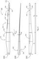
- Fig. 2 shows schematically and exemplarily a rotor blade 200 of a wind turbine, such as in Fig. 1 shown in three views 200A, 200B, 200C.
- the rotor blade 200 has a leading edge 202, a trailing edge 204, a suction side 206, a pressure side 208 and a length Ir.
- the rotor blade 200 is shown from above, i.e. looking at the suction side 206.
- the rotor blade 200 is shown from behind, i.e. looking at the trailing edge 204.
- the rotor blade 200 is shown from below, i.e. looking at the pressure side 208.
- the rotor blade 200 is designed as a two-part rotor blade 200, namely from a first rotor blade component 210 and a second rotor blade component 220, which can be joined together at a separation point 230 to form the actual rotor blade 200.
- a separation point 230 to form the actual rotor blade 200.
- functional or constructive measures are required which extend from the separation point into the rotor blade components 210, 220, in particular into an area B 230 around the separation point.
- the rotor blade 200 is typically divided into individual rotor blade components 210, 220 and transported to the installation site of the wind turbine 100 and assembled on site.
- structural precautions must be taken at the separation point 230, for example thicker layers of material, in order to ensure a reliable connection, for example by bolts or by gluing at the construction site.
- the first rotor blade component 210 and the second rotor blade component 220 are connected to one another in particular lengthwise, i.e. such that the rotor blade 200 has a length I r which is essentially composed of the length I 1 of the first rotor blade component 210 and the length I 2 of the second rotor blade component 220.
- the first rotor blade component 210 comprises a first end 212 for arranging at a blade connection of the wind turbine 100 and a second end 214, which is connected in particular to the first end 222 of the second rotor blade component 220.
- the first rotor blade component 210 can also be referred to as a hub-near rotor blade component.
- the second rotor blade component 220 includes a first end 222, which is connected to the second end 214 of the first rotor blade component 214, and a second end 224, which may also be referred to as a rotor blade tip.
- the second rotor blade component 220 is designed to be significantly longer than the first rotor blade component 210, in particular such that the separation point lies in a range between 15 percent and 40 percent of the length I r of the rotor blade 200.
- the rotor blade optionally has serrations 240 on the trailing edge 206, in particular on the second rotor blade component 220, as well as a Gurney flap 250 on the pressure side 208.
- the Gurney flap 250 particularly preferably extends both over a part of the first rotor blade component 210 and over a part of the second rotor blade component 220 and is therefore arranged in particular in the region of the separation point 230.
- the rotor blade 200 further has an aerodynamically open profile (P), in particular at the separation point 230, as for example in Fig. 3 shown.
- P aerodynamically open profile
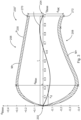
- Fig. 3 shows schematically and exemplarily a profile P 230 of a rotor blade, e.g. as in Fig. 2 shown at a separation point 230 of the rotor blade in a view 230 ⁇ , in particular in cross section.
- Fig. 3 the profile P 230 of the rotor blade 200 can be seen at the separation point 230.
- the profile of the rotor blade 200 is not closed; in this example, the trailing edge has a finite thickness d HK .
- an aerodynamically open profile of the present invention is not limited to this.
- the shape of the trailing edge can also be curved and is not limited to a straight line.
- the direction of the trailing edge can also deviate from a direction perpendicular to the profile depth.
- a sharp transition between the trailing edge and the pressure side 208 or the suction side 206 is not required.
- a continuous or rounded transition can also be provided.
- the thickness of the trailing edge d HK is then determined as the distance between the respective local curvature maxima on the pressure side 208 or the suction side 206, which then define the respective outflow points 270, 272.
- the view 230 ⁇ is supplemented by a Cartesian coordinate system.
- the local profile depth t base is plotted as a percentage on the abscissa of the coordinate system.
- the local profile thickness d base is also plotted as a percentage on the ordinate of the coordinate system, in particular in relation to the profile depth.
- both the second end 214 of the first rotor blade component 210 and the first end 222 of the second rotor blade component 220 have the profile P 230. This enables in particular a positive connection of the two rotor blade components 210, 220 at the separation point 230 of the rotor blade 200.
- the profile P 230 is aerodynamically open, ie the upper side 206 and the lower side 208 of the rotor blade are spaced apart at the trailing edge 204 by a thickness d HK , for example by 1.5 m or as in Fig. 4 shown.
- the P 230 profile has a chord t that runs directly between the leading edge 202 and the trailing edge 204.
- the profile P 230 also has a profile thickness d whose local maximum d max is at approximately 22 percent of the profile depth. This means in particular that the rotor blade has its maximum thickness at approximately 22 percent of the profile depth.
- the distance between the leading edge 202 and the point of maximum thickness d max of the profile P 230 is also referred to as the thickness offset x d .
- the ratio of the thickness offset x d to the profile depth t is also referred to as the relative thickness offset x d '.
- the rotor blade 200 has a material thickening M+ at the separation point 230 or in the area B 230 of the separation point 230, which can also be referred to as preform thickening.
- the material thickening M+ is preferably more than 0.2m and less than 1.0m, preferably between 0.3m and 0.7m, in particular approximately 0.5m.
- the material thickening M+ is to be understood here as an overall structural thickening, which can extend both outwards to increase the profile, i.e. as a contour thickening, but also inwards the profile.
- the rotor blade 200 also has only a slight curvature at the separation point 230 or in the area B 230 of the separation point 230.
- the slight curvature is illustrated by the flat skeleton line s.
- the rotor blade 200 has a so-called back swing at the separation point 230 or in the area B 230 of the separation point 230, i.e. a negative curvature, which is illustrated by the negative course of the skeleton line.
- the skeleton line s therefore has at least one change of sign, in particular in a range between 40 percent and 70 percent of the length I r of the rotor blade.
- Fig. 4 shows schematically and exemplarily a profile of the thickness d HK of the trailing edge 204 over the length I r of the rotor blade 200.
- the trailing edge 204 of the rotor blade is pulled up to the area B 230 of the separation point, e.g. up to 1.5m, and reaches its maximum there, e.g. exactly at the separation point.
- the trailing edge then tapers to 0m, e.g. at a blade length of 45m.
- the profile P of the rotor blade is open up to a blade length of 45 m and is then closed up to the blade tip at 100 m.
- the profile P of the rotor blade 200 is therefore only open in sections and in particular at the separation point 230.
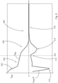
- Fig. 5 shows schematically and exemplarily an alternative course of the thickness d HK of the trailing edge 204 over the length I r of the rotor blade 200 as well as the associated derivative d HK /d r
- the thickness d HK is monotonically decreasing, the maximum is therefore already at or in the vicinity of the blade connection.
- the solution according to the invention can now be seen particularly well in the lower or negative part of the Fig. 5 , in which the derivative d HK /d r is shown.
- the derivative or change in the thickness of the trailing edge d HK /d r is negative over the entire length of the rotor blade, which means that the thickness of the trailing edge is monotonically decreasing.
- the separation point 230 is implemented in the region 512 in which the change in the thickness of the trailing edge d HK /d r has a local maximum. In comparison with this, the thickness of the trailing edge decreases more in the two surrounding regions 510 and 514, which means that the change in the thickness of the trailing edge d HK /d r in the regions 510 and 514 is greater in magnitude. Since the thickness of the trailing edge in the region 508 is zero, the change in the thickness of the trailing edge d HK /d r in the corresponding region 516 is also zero.
Landscapes
- Engineering & Computer Science (AREA)
- Life Sciences & Earth Sciences (AREA)
- Sustainable Development (AREA)
- Sustainable Energy (AREA)
- Chemical & Material Sciences (AREA)
- Combustion & Propulsion (AREA)
- Mechanical Engineering (AREA)
- General Engineering & Computer Science (AREA)
- Physics & Mathematics (AREA)
- Fluid Mechanics (AREA)
- Wind Motors (AREA)
Abstract
Description
- Die vorliegende Erfindung betrifft ein Rotorblatt einer Windenergieanlage sowie eine, ein solches Rotorblatt aufweisende Windenergieanlage.
- Windenergieanlagen sind allgemein bekannt und üblicherweise als Auftriebsläufer mit horizontaler Achse und drei Rotorblättern auf der Luvseite ausgeführt.
- Die Länge und die Form der Rotorblätter sind dabei - neben den vorherrschenden Windverhältnissen am Standort der Windenergieanlage - maßgeblich für den Ertrag einer Windenergieanlage. Insbesondere kann mit zunehmender Länge der Rotorblätter der Ertrag der Windenergieanlage gesteigert werden.
- Insoweit sind lange Rotorblätter wünschenswert.
- Mit zunehmender Länge der Rotorblätter erhöhen sich aber auch die konstruktiven Anforderungen, bspw. an das Gewicht oder das Strömungsverhalten.
- Hinzu kommt, dass für den Transport zum Standort der Windenergieanlage logistische Anforderungen berücksichtigt werden müssen, was bspw. dazu führt, dass Rotorblätter mit einer Länge von über 70 Metern häufig mehrteilig ausgeführt werden. Dies bedeutet insbesondere, dass die Rotorblätter ab Werk mehrteilig ausgeführt sind und erst am Standort der Windenergieanlage zusammengesetzt werden.
- Das Zusammensetzen erfolgt dabei beispielsweise mittels Bolzen, die eine Materialaufdickung an der entsprechenden Stelle (Trennstelle) benötigen, was zu einer Profilverschiebung führen kann, die sich ungünstig auf das Strömungsverhalten des Rotorblattes auswirken kann.
- Insoweit sind für geteilte Rotorblätter gesonderte Profile notwendig.
- Aufgabe der Offenbarung ist es wenigstens eines der oben genannten Probleme zu adressieren, insbesondere soll ein geteiltes Rotorblatt bereitgestellt werden, welches den aerodynamischen Anforderungen an lange Rotorblätter gerecht wird.
- In einem Aspekt wird somit ein Rotorblatt einer Windenergieanlage vorgeschlagen, wenigstens umfassend eine erste Rotorblattkomponente mit einem ersten Ende zum Anordnen an der Windenergieanlage, und einem zweiten Ende zum Verbinden mit einer zweiten Rotorblattkomponente; eine zweite Rotorblattkomponente mit einem ersten Ende zum Anordnen an der ersten Rotorblattkomponente, und einem zweiten Ende, wobei die erste Rotorblattkomponente mit der zweiten Rotorblattkomponente an einer Trennstelle zu dem Rotorblatt verbindbar ist, wobei das Rotorblatt an der Trennstelle ein aerodynamisch offenes Profil aufweist.
- Die Trennstelle trennt das Rotorblatt vorzugsweise in Rotorblattlängsrichtung, so dass die erste Rotorblattkomponente auch als Wurzelkomponente und die zweite Rotorblattkomponente auch als Blattspitzenkomponente bezeichnet werden kann. Unabhängig davon kann sowohl die Rotorblattkomponente als auch die Blattspitzenkomponente in einigen Ausführungen selbst aus mehreren Einzelteilen bestehen, beispielsweise selbst auch eine oder mehrere Trennstellen aufweisen.
- Es wird also ein zumindest zweiteiliges Rotorblatt einer Windenergieanlage vorgeschlagen, welches wenigstens an einer Trennstelle, insbesondere zwischen der ersten Rotorblattkomponente und der zweiten Rotorblattkomponente, ein aerodynamisch offenes Profil aufweist.
- Ein aerodynamisch offenes Profil kann beispielsweise dadurch erreicht werden, dass die Oberseite bzw. Saugseite des Rotorblattes und die Unterseite bzw. Druckseite des Rotorblattes an der Hinterkante des Rotorblattes voneinander beabstandet sind. Insbesondere ist ein aerodynamisch offenes Profil von einem aerodynamisch geschlossenen Profil zu unterscheiden, bei dem ein Abströmpunkt auf der Druckseite dem Abströmpunkt auf der Saugseite entspricht.
- Unter einem aerodynamisch offenen Profil wird hierin demnach ein aerodynamisches Profil verstanden, bei dem eine Strömung an einer Vorderkante in eine Strömung über die Saugseite und eine Strömung über die Druckseite aufgeteilt wird und diese aufgeteilte Strömung an zwei voneinander beabstandeten Punkten auf der Saugseite und der Druckseite abströmt.
- Eine Möglichkeit der Realisierung eines aerodynamisch offenen Profils stellt eine sogenannte "stumpfe" oder "dicke" Hinterkante dar, bei der die Hinterkante eine endliche Ausdehnung zwischen einer druckseitigen Hinterkante und einer saugseitigen Hinterkante aufweist. Andere Möglichkeiten sind beispielsweise das Vorsehen von strömungsbeeinflussenden Anbauteilen wie Gurney-Flaps, wobei ein Abströmpunkt üblicherweise auf der Druckseite die Spitze der Gurney-Flap ist. Auch sind C-förmige bzw. hohle Profile möglich.
- Das Rotorblatt kann also neben der ersten Rotorblattkomponente und der zweiten Rotorblattkomponente auch noch weitere Segmente oder Bauteile aufweisen, wie bspw. ein, insbesondere zusätzliches, Hinterkantensegment. Die wesentliche Form und Erscheinung des Rotorblattes wird aber durch die erste und zweite Rotorblattkomponente bestimmt, die bevorzugt der Länge nach zu dem eigentlichen Rotorblatt, insbesondere formschlüssig, verbunden werden.
- Die auch als nabennahe Komponente bezeichnete erste Rotorblattkomponente weist bevorzugt ein erstes Ende auf, welches dazu eingerichtet ist, mit der Windenergieanlage, insbesondere einer (Rotor-)Nabe der Windenergieanlage, verbunden zu werden. Das erste Ende ist hierfür bevorzugt als Blattflansch oder Blattwurzel ausgebildet.
- Die erste Rotorblattkomponente weist zudem ein zweites Ende auf, welches dazu eingerichtet ist, mit der zweiten Rotorblattkomponente, insbesondere einem ersten Ende der zweiten Rotorblattkomponente, verbunden zu werden, bspw. durch Bolzen oder Verkleben oder Gelege.
- Die auch als nabenferne Komponente bezeichnete zweite Rotorblattkomponente weist bevorzugt ein erstes Ende auf, welches dazu eingerichtet ist, mit der ersten Rotorblattkomponente, insbesondere einem zweiten Ende der ersten Rotorblattkomponente, verbunden zu werden, bspw. durch Bolzen oder Verkleben oder Gelege.
- Die zweite Rotorblattkomponente weist zudem ein zweites Ende auf, welches im Wesentlichen zulaufend, bevorzugt spitz zulaufend, ausgeführt ist und/oder als Spitze (engl.: tip) des Rotorblattes ausgebildet ist.
- Das Rotorblatt weist zudem eine Trennstelle auf, die bevorzugt im Wesentlichen quer zur Längsrichtung des Rotorblattes verläuft.
- Die Rotorblattkomponenten sind an eben jener Trennstelle miteinander verbunden, insbesondere so, dass die Summe der Längen der Rotorblattkomponenten im Wesentlichen die Länge des Rotorblattes ergibt.
- Bevorzugt weist die Trennstelle zudem eine Materialverdickung, eine sogenannte Preformaufdickung auf. Dies kann bspw. dadurch erreicht werden, dass das zweite Ende der ersten Rotorblattkomponente und das erste Ende der zweiten Rotorblattkomponente mit Material aufgedickt werden, bspw. durch zusätzliche Lagen an glasfaserverstärktem Kunststoff (GFK) und/oder kohlenstofffaserverstärktem Kunststoff (CFK) oder dergleichen.
- Vorzugsweise weist das Rotorblatt in Rotorblattlängsrichtung einen Verlauf unterschiedlicher Profile mit jeweils einer Vorderkante, einer Hinterkante und die Vorder- und Hinterkante verbindenden druckseitigen und saugseitigen Strömungsflächen auf, wobei die Hinterkante in wenigstens einem Abschnitt in Rotorblattlängsrichtung, in dem die Trennstelle liegt, als dicke Hinterkante ausgeführt ist und damit das aerodynamisch offene Profil ausbildet.
- Bei dicken Hinterkanten kann eine Richtung der Dicke der Hinterkante im Wesentlichen parallel zu der Rotorblattdicke und orthogonal zu der Rotorblattlänge und orthogonal zu der Rotorblatttiefe ausgerichtet sein. Eine Dicke der Hinterkante des Rotorblattes kann jedoch auch für solche Profile definiert werden, die abgerundete Ecken oder auch strukturell geschlossene Profile, insbesondere in Tropfenform, aufweisen.
- Hierbei bildet in dem Profilverlauf des Rotorblattes die jeweils druckseitige bzw. saugseitige Hinterkantenkontur vorzugsweise jeweils eine Abströmkante. Als Dicke der Hinterkante wird bei solchen Profilen insbesondere im Profilschnitt der Abstand des saugseitigen Abströmpunktes und des druckseitigen Abströmpunktes verstanden. Anders ausgedrückt verbinden die Abströmkanten im Profilverlauf die jeweiligen Abströmpunkte der zugehörigen Profilschnitte. Um die Dicke der Hinterkante zu definieren wird der jeweilige Abströmpunkt insbesondere als lokales Krümmungsmaximum sowohl auf der Druckseite als auch auf der Saugseite definiert. Üblicherweise können sowohl druckseitig als auch saugseitig mehr als ein lokales Krümmungsmaximum auftreten, wobei in diesem Fall der jeweilige Abströmpunkt das von der Vorderkante am weitesten entfernte lokale Krümmungsmaximum ist.
- Die Hinterkante kann dabei integraler Bestandteil der ersten und/oder der zweiten Rotorblattkomponente sein, oder ein ein- oder mehrteiliges Bauteil sein, welches an der ersten und/oder der zweiten Rotorblattkomponente, bspw. durch Bolzen oder Verkleben, befestigt ist oder wird.
- Vorzugsweise ist die dicke Hinterkante durch an der Hinterkante beabstandete druckseitige und saugseitige Strömungsflächen, d.h. jeweils beabstandete Abströmpunkte, ausgebildet, wobei der Abstand zwischen druckseitiger und saugseitiger Strömungsfläche an der Hinterkante als Dicke der Hinterkante bezeichnet wird.
- Vorzugsweise weist ein Verlauf der Dicke der Hinterkante wenigstens ein Maximum auf und die Dicke der Hinterkante beträgt im Bereich der Trennstelle besonders bevorzugt wenigstens 50 Prozent, bevorzugt 60 Prozent, weiter bevorzugt 80 Prozent, dieses Maximums.
- Alternativ oder zusätzlich liegt das Maximum in einem Bereich um die Trennstelle, wobei der Bereich um die Trennstelle zwischen 15 Prozent und 40 Prozent der Länge des Rotorblattes liegt und/oder der Bereich kleiner als 10 Prozent der Länge des Rotorblattes ist.
- Die Dicke der Hinterkante ist ein absoluter Wert, der unabhängig von anderen geometrischen Parametern des Rotorblattes einen einfach zu bestimmenden Verlauf über die Länge des Rotorblattes annimmt. Indem das Maximum der Dicke der Hinterkante in einem bestimmten Bereich aufweist, nämlich in Bezug auf die Position der Trennstelle, ergibt sich ein besonders vorteilhaftes Rotorblatt.
- Hierbei kann sowohl die Dicke der Hinterkante an der Trennstelle einen bestimmten Mindestwert, bezogen auf die maximale Dicke der Hinterkante, aufweisen, und/oder die Position des Maximums nicht über einen bestimmten Betrag von der Trennstelle entfernt liegen. In beiden alternativen bzw. sich ergänzenden Beschreibungen besteht also ein Zusammenhang zwischen der Position der Trennstelle und der Dicke der Hinterkante.
- Wenn in einem Blattentwurf beispielsweise ein Maximum der Dicke der Hinterkante weiter in Richtung der Rotorblattspitze wandert, so hat es sich als vorteilhaft herausgestellt, auch die Trennstelle entsprechend weiter in Richtung der Rotorblattspitze zu legen. Anders herum hat sich herausgestellt, dass es vorteilhaft ist, den Verlauf der Dicke der Hinterkante an die Position einer festgelegten Trennstelle anzupassen.
- Während in dieser Ausführung der absolute Wert der Dicke der Hinterkante herangezogen wird, so lassen sich in anderen Ausführungen vergleichbare Zusammenhänge auch mit auf die Rotorblattdicke bzw. die Rotorblatttiefe bezogene Dicken der Hinterkante, also relative Hinterkantendicken bezogen auf Rotorblattdicke und/oder bezogen auf Rotorblatttiefe, heranziehen. Auch hier hat sich gezeigt, dass es vorteilhaft ist, wenn sich ein entsprechendes lokales Maximum des Verlaufs der relativen Dicke der Hinterkante ausbildet, an dessen Position sich die Position der Trennstelle orientiert.
- In einer Ausführung liegt die Trennstelle näher an einer Rotorblattspitze des Rotorblattes als das Maximum der Dicke der Hinterkante.
- Damit ist zunächst vorteilhaft, dass die Hinterkante im Bereich der Trennstelle in Rotorblattlängsrichtung konvergiert, also die druckseitige Hinterkante und die saugseitige Hinterkante aufeinander zulaufen. Zudem ist vorteilhaft, dass die Position der Trennstelle, in Rotorblattlängsrichtung, nicht vor sondern hinter dem Maximum liegt. Die zusätzlichen strukturellen Anforderungen und damit bspw. Gewichtserhöhungen an der Trennstelle resultieren in zusätzlichen strukturellen Lasten durch die Trennstelle, deren Auswirkungen durch die Anordnung hinter dem Maximum, also näher an der Rotorblattspitze, zumindest verringert werden können.
- In anderen Ausführungen hat es sich als vorteilhaft herausgestellt, bereits in Umgebung der Rotorblattnabe eine dicke Hinterkante vorzusehen. Anstelle des Verlaufs mit Maximum der Dicke der Hinterkante im Bereich der Trennstelle, kann dann das Maximum der Dicke der Hinterkante bereits an der Blattwurzel anliegen.
- Vorzugsweise ist der Verlauf der Dicke der Hinterkante in dieser Ausführung monoton fallend, nimmt also monoton mit steigendem Abstand von der Rotorblattwurzel ab. Das Maximum der Dicke der Hinterkante ist also an bzw. in Umgebund der Rotorblattwurzel ausgebildet.
- Besonders bevorzugt wird in dieser Ausführung ein besonderer Verlauf der Änderung der Dicke der Hinterkante vorgesehen. Die Änderung der Dicke der Hinterkante kann besonders bevorzugt als Ableitung der Dicke der Hinterkante in Rotorblattlängs- oder auch Radius-richtung ausgedrückt werden. Ein monoton fallender Verlauf der Dicke der Hinterkante hat demnach eine über den gesamten Rotorradius negative bzw. jedenfalls nicht positive Ableitung, also eine "negative" Änderung.
- Insbesondere ab einem bestimmten Bereich in Rotorblattlängsrichtung, ab dem die Hinterkante keine endliche Ausdehnung oder Dicke mehr zeigt, wird auch keine weitere Änderung der Dicke der Hinterkante auftreten.
- Besonders bevorzugt liegt ein lokales Maximum der Änderung der Dicke der Hinterkante an der Trennstelle oder in einem Bereich um die Trennstelle, wobei der Bereich um die Trennstelle zwischen 15 Prozent und 40 Prozent der Länge des Rotorblattes liegt und/oder der Bereich kleiner als 10 Prozent der Länge des Rotorblattes ist.
- In einer Alternative ist daher die absolute Lage des Bereichs bezogen auf das Rotorblatt formuliert. In der anderen Alternative ist die Ausdehnung des Bereichs bezogen auf die Trennstelle formuliert.
- Dass das lokale Maximum innerhalb des Bereichs liegt bedeutet hierbei vorzugsweise, dass bereits innerhalb des Bereichs beiderseitig des lokalen Maximums eine betragsmäßig größere Änderung der Dicke der Hinterkante vorliegt. Anders ausgedrückt bei dem lokalen Maximum handelt es sich insbesondere nicht um einen Wert am Rand des Bereichs.
- Besonders bevorzugt befindet sich das lokale Maximum der Änderung der Dicke in einem Bereich kleiner als 5 Prozent der Länge des Rotorblattes um die Trennstelle.
- In einer Ausführung verläuft die Druckseite, an der Trennstelle im Bereich der Hinterkante, konkav.
- Ein konkaver Verlauf der Druckseite bedeutet, dass die Druckseite im Bereich der Hinterkante nach innen, also in Richtung der Saugseite, gekrümmt verläuft.
- In einer Ausführung ist eine Krümmung der Druckseite an der Trennstelle im Bereich der Hinterkante betragsmäßig größer als die Krümmung der Saugseite an der Trennstelle im Bereich der Hinterkante.
- Damit kann das Profil an der Trennstelle an der Hinterkante als divergierend bezeichnet werden. Vorteilhaft divergieren zwei Tangenten, die jeweils an den saugseitigen Abströmpunkt und den druckseitigen Abströmpunkt angelegt werden, hinter der Hinterkante.
- In einer Ausführung wird eine direkte Verbindung zwischen Vorderkante und Hinterkante als Profilsehne und deren Länge als Profiltiefe bezeichnet, ein größter Abstand zwischen druckseitiger und saugseitiger Profilfläche senkrecht auf der Profiltiefe wird als Profildicke bezeichnet und ein Verhältnis aus Profildicke zu Profiltiefe wird als relative Dicke bezeichnet, wobei ein Verlauf der relativen Dicke über die Rotorblattlänge als Dickenverlauf bezeichnet wird.
- In einer Ausführung weist eine Änderung des Dickenverlaufs im Bereich der Trennstelle ein lokales Maximum auf.
- In dieser Ausführung wird als der Bereich der Trennstelle vorzugsweise ein Bereich von 5% der Rotorblattlänge, auch als "5%L" bezeichnet, verstanden, in dessen Mitte sich die Trennstelle befindet. Indem die Änderung des Dickenverlaufs ein lokales Maximum im Bereich der Trennstelle aufweist, wird nach der Trennstelle, das heißt, von der Trennstelle aus betrachtet in Richtung Rotorblattspitze, eine zügige Reduktion der relativen Dicke erfolgen. Damit können die strukturell bedingten und aerodynamisch unvorteilhaften Verstärkungen an der Trennstelle möglichst rasch kompensiert werden, was zu einem effizienteren Rotorblatt führt.
- Diese bevorzugte Beschreibung des Bereichs der Trennstelle ist ebenso auf die Ausführungen zur Dicke der Hinterkante bzw. die Änderung der Dicke der Hinterkante anwendbar.
- Besonders bevorzugt weist der Dickenverlauf genau an der Trennstelle ein Plateau auf, die Änderung des Dickenverlaufs also genau an der Trennstelle ein Minimum. Dies ist der Fall, da der absolute Dickenverlauf durch Aufdickung oder ähnliches an der Trennstelle ein Maximum aufweist, um beispielsweise die Befestigungsbolzen zum Befestigen der Rotorblattkomplenten aufzunehmen.
- In einer Ausführung ist die Änderung des Dickenverlaufs als Ableitung des Dickenverlaufs nach der Richtung der Rotorblattlänge definiert.
- In einer Ausführung ändert eine Krümmung des Dickenverlaufs im Bereich der Trennstelle die Richtung, wobei die Krümmung insbesondere als zweite Ableitung des Dickenverlaufs nach der Richtung der Rotorblattlänge definiert ist und sich die Richtung bei einem Vorzeichenwechsel ändert.
- In einer Ausführung ist die Änderung des Dickenverlaufs um die Trennstelle unsymmetrisch ausgeführt. Das bedeutet, dass die Änderung des Dickenverlaufs vor der Trennstelle an wenigstens einer Stelle größer oder kleiner als an einer entsprechenden Position hinter der Trennstelle ausgeführt ist. Hier und im Folgenden wird unter der Bezeichnung "vor der Trennstelle" der Teil des Rotorblattes von der Rotorblattnabe bis zur Trennstelle und "hinter der Trennstelle" der Teil des Rotorblattes ab der Trennstelle bis zur Rotorblattspitze verstanden.
- Besonders bevorzugt weist das Rotorblatt in einem gesamten Bereich von 5% nabennäher der Trennstelle eine geringere oder gleiche Abnahme des Dickenverlaufs als symmetrisch in dem Bereich von 5% nabenferner der Trennstelle auf, wobei besonders bevorzugt an einer Position 5% nabennäher der Trennstelle eine geringere Abnahme des Dickenverlaufs als an einer Position 5% nabenferner der Trennstelle ausgebildet ist.
- Die in dieser Ausführung stärkere Abnahme hinter der Trennstelle ermöglicht es, rasch hinter der Trennstelle zu aerodynamisch vorteilhaften dünnen Profilen zu gelangen.
- Vorzugsweise beträgt die relative Dicke an der Trennstelle zwischen 40% und 80%.
- Eine relative Position der maximalen Profildicke, bezogen auf die Profilsehne, wird als Dickenrücklage bezeichnet. In einer Ausführung beträgt die Dickenrücklage an der Trennstelle kleiner als 30%. Damit ist die maximale Profildicke signifikant vor dem Mittelpunkt der Profiltiefe in Richtung der Vorderkante, was zu einem aerodynamisch vorteilhaften Rotorblatt beiträgt.
- Eine Verbindung der Innenkreise des Profils wird als Skelettlinie bezeichnet. Eine Wölbung wird als Abstand der Skelettlinie von der und senkrecht zu der Profilsehne definiert. In einer Ausführung weist ein Verlauf der Wölbung entlang der Profiltiefe ein Maximum in den hinteren 50%, gemessen ab der Vorderkante, auf.
- Der Begriff "Maximum" impliziert nicht, dass die Wölbung in irgendeinem einem Bereich positiv ausgeführt sein muss. Falls die Wölbung über die gesamte Profiltiefe negativ verläuft, ist das Maximum der Wölbung entsprechend ein betragsmäßiges Minimum.
- Vorzugsweise ändert sich ein Vorzeichen der Wölbung in den vorderen 70% der Profiltiefe, gemessen ab der Vorderkante, insbesondere in einem Bereich zwischen 40% und 70% der Profiltiefe.
- Das Vorzeichen der Wölbung kann anders ausgedrückt auch als eine Position des Zentrums der Innkreise bezüglich der Profilsehne bezeichnet werden. Ein positives Vorzeichen wird vorzugsweise bei einer Wölbung in Richtung der Saugseite, ein negatives Vorzeichen bei einer Wölbung in Richtung der Druckseite festgelegt.
- Vorzugsweise beträgt ein Wert der Wölbung an der Trennstelle an jeder Position in Profiltiefenrichtung zwischen plus und minus 10%, insbesondere zwischen plus und minus 7%, bezogen auf die Profiltiefe an der Trennstelle.
- Besondere Vorteile ergibt sich eine Kombination dieser Wölbungsverteilung mit der oben beschriebenen Dickenrücklage an der Trennstelle.
- Vorzugsweise weist das Rotorblatt eine Länge von wenigstens 70m, bevorzugt wenigstens 80m, weiter bevorzugt wenigstens 100m, auf.
- Vorzugsweise beträgt die maximale Profiltiefe des Rotorblattes höchstens 6,5% der Länge des Rotorblattes.
- Die Profiltiefe wird insbesondere als Tiefe der profilgebenden Kontur ohne Anbauteile bestimmt. Die Einhaltung dieser Obergrenze für die maximale Profiltiefe ermöglicht, dass Blattmasse, strukturelle Komplexitäten und Transportmaße eingehalten werden. Beispielsweise kann auch bei einem Rotorblatt von 95 m Rotorblattlänge die Profiltiefe deutlich unterhalb der Grenze von 6,5% und beispielsweise bei höchstens 4,10 m liegen, um Transportbeschränkungen zu vermeiden.
- Vorzugsweise weist das Rotorblatt wenigstens einen Vortex-Generator und/oder eine Gurney-Flap und/oder eine Splitter-Platte und/oder einen Grenzschichtzaun und/oder Serrations auf, insbesondere am oder auf dem ersten und zweiten länglichen Körper.
- Durch diese oder andere bevorzugte Anbauteile, entweder einzeln oder in Kombination, können die positiven Eigenschaften des erfindungsgemäßen Rotorblattes weiter verbessert werden.
- Vorzugsweise weist die erste Rotorblattkomponente eine Länge auf und die zweite Rotorblattkomponente weist eine Länge auf, wobei die Länge der ersten Rotorblattkomponente kürzer ist als die Länge der zweiten Rotorblattkomponente, insbesondere so, dass die Trennstelle in einem Bereich des Rotorblattes zwischen 20 Prozent und 35 Prozent der Länge des Rotorblattes angeordnet ist.
- In einem weiteren Aspekt wird eine Windenergieanlage mit wenigstens einem Rotorblatt gemäß dem vorbeschriebenen Aspekt vorgeschlagen.
- Schließlich wird in einem weiteren Aspekt auch ein Windpark mit mehreren Windenergieanlagen gemäß dem vorbeschriebenen Aspekt vorgeschlagen.
- Sowohl die Windenergieanlage als auch der Windpark ermöglichen die gleichen Vorteile, insbesondere bei entsprechend großer Dimensionierung, zu erreichen, wie sie für das Rotorblatt gemäß der Offenbarung beschrieben sind. Zudem ergeben sich besondere Vorteile durch Kombination mit einer oder mehrerer der als bevorzugt beschriebenen Ausführungsformen.
- Die vorliegende Offenbarung wird nun nachfolgend anhand der begleitenden Figuren näher erläutert, wobei für gleiche oder ähnliche Baugruppen dieselben Bezugszeichen verwendet werden.
- Fig. 1
- zeigt schematisch und exemplarisch eine perspektivische Ansicht einer Windenergieanlage.
- Fig. 2
- zeigt schematisch und exemplarisch ein Rotorblatt einer Windenergieanlage, insbesondere in drei Ansichten.
- Fig. 3
- zeigt schematisch und exemplarisch ein Profil eines Rotorblattes einer Windenergieanlage an einer Trennstelle des Rotorblattes, insbesondere in einem Querschnitt.
- Fig. 4
- zeigt schematisch und exemplarisch einen Verlauf eines Teils eines Profils eines Rotorblattes einer Windenergieanlage entlang einer Länge des Rotorblattes.
- Fig. 5
- zeigt schematisch und exemplarisch einen Verlauf einer Dicke der Hinterkante und einer zugehörigen Hinterkante entlang einer Länge des Rotorblattes.
-
Fig. 1 zeigt schematisch und exemplarisch eine perspektivische Ansicht einer Windenergieanlage 100. Die Windenergieanlage 100 ist als Auftriebsläufer mit horizontaler Achse und drei Rotorblättern 200 auf der Luvseite, insbesondere als Horizontalläufer, ausgebildet. Die Windenergieanlage 100 weist einen Turm 102 und eine Gondel 104 auf. - An der Gondel 104 ist ein aerodynamischer Rotor 106 mit einer Nabe 110 angeordnet. An der Nabe 110 sind drei Rotorblätter 200, insbesondere symmetrisch zur Nabe 110, angeordnet, bevorzugt um 120° versetzt. Die Rotorblätter 200 sind bevorzugt wie vorstehend und/oder nachstehend beschrieben ausgeführt.
-
Fig. 2 zeigt schematisch und exemplarisch ein Rotorblatt 200 einer Windenergieanlage, wie bspw. inFig. 1 gezeigt, in drei Ansichten 200A, 200B, 200C. - Das Rotorblatt 200 weist eine Vorderkante 202, eine Hinterkante 204, eine Saugseite 206, eine Druckseite 208 und eine Länge Ir auf. In der ersten Ansicht 200A ist das Rotorblatt 200 dabei von oben gezeigt, also mit Blick auf die Saugseite 206.
- In der zweiten Ansicht 200B ist das Rotorblatt 200 von hinten gezeigt, also mit Blick auf die Hinterkante 204.
- In der dritten Ansicht 200C ist das Rotorblatt 200 von unten gezeigt, also mit Blick auf die Druckseite 208.
- Das Rotorblatt 200 ist als zweiteiliges Rotorblatt 200 ausgeführt, nämlich aus einer ersten Rotorblattkomponente 210 und einer zweiten Rotorblattkomponente 220, die an einer Trennstelle 230 zu dem eigentlichen Rotorblatt 200 zusammenfügbar sind. Hierfür sind bspw. funktionale oder konstruktive Maßnahmen erforderlich, die von der Trennstelle aus in die Rotorblattkomponenten 210, 220 hineinreichen, insbesondere in einen Bereich B230 um die Trennstelle.
- Das Rotorblatt 200 wird typischerweise aus Transportgründen in einzelne Rotorblattkomponenten 210, 220 aufgeteilt an den Errichtungsort der Windenergieanlage 100 transportiert und vor Ort zusammengefügt. Dafür sind an der Trennstelle 230 strukturelle Vorkehrungen zu treffen, beispielsweise dickere Materialschichten, um eine zuverlässige Verbindung beispielsweise durch Bolzen oder durch Verkleben an der Baustelle zu gewährleisten.
- Es ist demnach üblicherweise unvermeidbar, dass im Bereich der Trennstelle 230, also in dem Bereich B230 ein höheres Gewicht und gegebenenfalls sogar weitere unerwünschte , beispielsweise aerodynamische, Effekte, wie beispielsweise unvorteilhafte Induktionsfaktoren oder Elastizitäten, auftreten. Die vorliegende Offenbarung erkennt diese Nachteile der Verwendung von geteilten Rotorblättern und schafft es, unter diesen als gegeben angenommenen Randbedingungen ein möglichst effizientes Rotorblatt zu schaffen.
- Die erste Rotorblattkomponente 210 und die zweite Rotorblattkomponente 220 sind insbesondere der Länge nach miteinander verbunden, also so, dass das Rotorblatt 200 eine Länge Ir aufweist, die sich im Wesentlichen aus der Länge I1 der ersten Rotorblattkomponente 210 und der Länge I2 der zweiten Rotorblattkomponente 220 zusammensetzt.
- Die erste Rotorblattkomponente 210 umfasst ein erstes Ende 212 zum Anordnen an einem Blattanschluss der Windenergieanlage 100 und ein zweites Ende 214, welches insbesondere mit dem ersten Ende 222 der zweiten Rotorblattkomponente 220 verbunden wird. Die erste Rotorblattkomponente 210 kann auch als nabennahe Rotorblattkomponente bezeichnet werden.
- Die zweite Rotorblattkomponente 220 umfasst ein erstes Ende 222, welches mit dem zweiten Ende 214 der ersten Rotorblattkomponente 214 verbunden wird und ein zweites Ende 224, welches auch als Rotorblattspitze bezeichnet werden kann.
- Bevorzugt ist die zweite Rotorblattkomponente 220 deutlich länger ausgeführt als die erste Rotorblattkomponente 210, insbesondere so, dass die Trennstelle in einem Bereich zwischen 15 Prozent und 40 Prozent der Länge Ir des Rotorblattes 200 liegt.
- Ferner weist das Rotorblatt optional Serrations 240 an der Hinterkante 206, insbesondere an der zweiten Rotorblattkomponente 220, sowie auf der Druckseite 208 eine Gurney-Flap 250 auf. Die Gurney-Flap 250 erstreckt sich besonders bevorzugt sowohl über einen Teil der ersten Rotorblattkomponente 210 als auch über einen Teil der zweiten Rotorblattkomponente 220 und ist demnach insbesondere in dem Bereich der Trennstelle 230 angeordnet.
- Das Rotorblatt 200 weist ferner insbesondere an der Trennstelle 230 ein aerodynamisch offenes Profil (P) auf, wie bspw. in
Fig. 3 gezeigt ist. -
Fig. 3 zeigt schematisch und exemplarisch ein Profil P230 eines Rotorblattes, bspw. wie inFig. 2 gezeigt, an einer Trennstelle 230 des Rotorblattes in einer Ansicht 230`, insbesondere im Querschnitt. -
Fig. 3 ist also insbesondere das Profil P230 des Rotorblattes 200 an der Trennstelle 230 zu entnehmen. - Insbesondere im Bereich der Trennstelle 230 ist das Profil des Rotorblattes 200 nicht geschlossen, in diesem Beispiel weist die Hinterkante eine endliche Dicke dHK auf. Dies bedeutet insbesondere, dass ein Abströmpunkt 270 auf der Saugseite 206 und ein Abströmpunkt 272 auf der Druckseite 208 an der Hinterkante voneinander mit einem Abstand dHK beabstandet sind.
- Während in der
Fig. 3 eine klassische "dicke Hinterkante" gezeigt ist, bei dem die Hinterkante quasi senkrecht auf der Protilfiete t steht und bei der eine scharfe Kante zu den jeweiligen Abströmpunkten auf Druckseite 208 und Saugseite 206 vorgesehen ist, so ist ein aerodynamisch offenes Profil der vorliegenden Erfindung nicht darauf beschränkt. - Die Form der Hinterkante kann auch gekrümmt sein und ist nicht auf eine gerade Linie beschränkt. Auch kann die Richtung der Hinterkante von einer zu der Profiltiefe senkrechten Richtung abweichen. Schließlich ist auch kein spitzer Übergang zwischen der Hinterkante und der Druckseite 208 bzw. der Saugseite 206 erforderlich. Beispielsweise kann auch ein kontinuierlicher oder abgerundeter Übergang vorgesehen sein. Die Dicke der Hinterkante dHK wird dann als der Abstand zwischen den jeweiligen lokalen Krümmungsmaxima auf der Druckseite 208 bzw. der Saugseite 206 bestimmt, die dann die jeweiligen Abströmpunkte 270, 272 definieren.
- Für ein besseres Verständnis und insbesondere um die hierin beschriebenen Relationen zu veranschaulichen, ist die Ansicht 230` um ein kartesisches Koordinatensystem ergänzt. Auf der Abszisse des Koordinatensystems ist dabei die lokale Profiltiefe tbase prozentual abgetragen. Auf der Ordinate des Koordinatensystems ist ferner die lokale Profildicke dbase prozentual abgetragen, insbesondere in Relation zur Profiltiefe.
- Bevorzugt weisen sowohl das zweite Ende 214 der ersten Rotorblattkomponente 210 als auch das erste Ende 222 der zweiten Rotorblattkomponente 220 das Profil P230 auf. Dies ermöglicht insbesondere einen Formschluss der beiden Rotorblattkomponenten 210, 220 an der Trennstelle 230 des Rotorblattes 200.
- Das Profil P230 ist aerodynamisch offen, d.h. die Oberseite 206 und die Unterseite 208 des Rotorblattes sind an der Hinterkante 204 um eine Dicke dHK voneinander beabstandet, bspw. um 1,5m oder wie in
Fig. 4 gezeigt. - Das Profil P230 weist eine Profilsehne t (engl. chord) auf, die direkt zwischen Vorderkante 202 und Hinterkante 204 verläuft.
- Das Profil P230 weist ferner eine Profildicke d auf, dessen lokales Maximum dmax bei ca. 22 Prozent der Profiltiefe liegt. Dies bedeutet insbesondere, dass das Rotorblatt bei ca. 22 Prozent Profiltiefe seine maximale Dicke aufweist. Der Abstand zwischen Vorderkante 202 und dem Punkt der maximalen Dicke dmax des Profils P230 wird auch als Dickenrücklage xd bezeichnet. Das Verhältnis der Dickenrücklage xd zur Profiltiefe t wird ferner auch als relative Dickenrücklage xd' bezeichnet.
- Das Rotorblatt 200 weist an der Trennstelle 230 bzw. im Bereich B230 der Trennstelle 230 eine Materialaufdickung M+ auf, die auch als Preformaufdickung bezeichnet werden kann. Bevorzugt beträgt die Materialaufdickung M+ mehr als 0,2m und weniger als 1,0m, vorzugsweise zwischen 0,3m und 0,7m, insbesondere ca. 0,5m. Die Materialaufdickung M+ ist hierbei als insgesamte Strukturverdickung zu verstehen, die sich sowohl profilvergrö-ßernd nach außen, also als Konturaufdickung, aber auch nach innerhalb des Profils erstrecken kann.
- Das Rotorblatt 200 weist an der Trennstelle 230 bzw. im Bereich B230 der Trennstelle 230 ferner nur eine geringe Krümmung auf. Die geringe Krümmung ist durch die flachverlaufende Skelettlinie s verdeutlicht.
- Zudem weist das Rotorblatt 200 an der Trennstelle 230 bzw. im Bereich B230 der Trennstelle 230 einen sogenannten back swing auf, also eine negative Krümmung, die durch den negativen Verlauf der Skelettlinie verdeutlich ist. Die Skelettlinie s weist also wenigstens einen Vorzeichenwechsel auf, insbesondere in einem Bereich zwischen 40 Prozent und 70 Prozent der Länge Ir des Rotorblattes.
-
Fig. 4 zeigt schematisch und exemplarisch einen Verlauf der Dicke dHK der Hinterkante 204 über die Länge Ir des Rotorblattes 200. - Die Hinterkante 204 des Rotorblattes wird bis in den Bereich B230 der Trennstelle aufgezogen, bspw. bis 1,5m, und erreicht dort ihr Maximum, bspw. genau auf der Trennstelle. Anschließend verjüngt sich die Hinterkante zu 0m, bspw. bei 45m Blattlänge.
- Dies bedeutet insbesondere, dass das Profil P des Rotorblattes bis 45m Blattlänge geöffnet ist und danach bis zur Blattspitze bei 100m geschlossen ist. Das Profil P des Rotorblattes 200 ist also nur abschnittsweise offen und insbesondere an der Trennstelle 230 offen.
-
Fig. 5 zeigt schematisch und exemplarisch einen alternativen Verlauf der Dicke dHK der Hinterkante 204 über die Länge Ir des Rotorblattes 200 sowie die zugehörige Ableitung dHK/dr Im Unterschied zu dem Verlauf derFig. 4 ist die Dicke dHK monoton fallend ausgebildet, das Maximum ist also bereits an dem bzw. in Umgebung des Blattanschlusses ausgeführt. - Zunächst erfolgt in einem Bereich 502 eine vergleichsweise starke Abnahme der Dicke der Hinterkante, die sich in einem Bereich 504 abflacht und in einem Bereich 506 dann wieder stärker abnimmt. In einem Bereich 508 ist die Dicke der Hinterkante Null, das aerodynamische Profil ist dort also geschlossen.
- Die erfindungsgemäße Lösung sieht man nun besonders gut im unteren bzw. negativen Teil der
Fig. 5 , in dem die Ableitung dHK/dr gezeigt ist. Die Ableitung bzw. Änderung der Dicke der Hinterkante dHK/dr ist über die gesamte Rotorblattlänge negativ, das heißt, dass die Dicke der Hinterkante monoton fallend ist. Die Trennstelle 230 ist in dem Bereich 512 ausgeführt, in dem die Änderung der Dicke der Hinterkante dHK/dr ein lokales Maximum aufweist. Verglichen hiermit verringert sich die Dicke der Hinterkante in den beiden umliegenden Bereichen 510 und 514 stärker, das heißt, dass die Änderung der Dicke der Hinterkante dHK/dr in den Bereichen 510 und 514 betragsmäßig größer ist. Da die Dicke der Hinterkante in dem Bereich 508 Null ist, ist die Änderung der Dicke der Hinterkante dHK/dr in dem entsprechenden Bereich 516 ebenfalls Null. -
- 100
- Windenergieanlage
- 102
- Turm
- 104
- Gondel, insbesondere der Windenergieanlage
- 106
- aerodynamischer Rotor, insbesondere der Windenergieanlage
- 110
- Nabe, insbesondere der Windenergieanlage
- 200
- Rotorblatt, insbesondere der Windenergieanlage
- 200A
- Rotorblatt, insbesondere in einer ersten Ansicht
- 200B
- Rotorblatt, insbesondere in einer zweiten Ansicht
- 200C
- Rotorblatt, insbesondere in einer dritten Ansicht
- 202
- Vorderkante, insbesondere des Rotorblattes
- 204
- Hinterkante, insbesondere des Rotorblattes
- 206
- Oberseite, insbesondere des Rotorblattes
- 208
- Unterseite, insbesondere des Rotorblattes
- 210
- erste Rotorblattkomponente
- 212
- erstes Ende, insbesondere der ersten Rotorblattkomponente
- 214
- zweites Ende, insbesondere der ersten Rotorblattkomponente
- 220
- zweite Rotorblattkomponente
- 222
- erste Ende, insbesondere der zweiten Rotorblattkomponente
- 224
- zweites Ende, insbesondere der zweiten Rotorblattkomponente
- 230
- Trennstelle des Rotorblattes
- 230'
- Ansicht der Trennstelle
- 240
- Serration
- 250
- Gurney-Flap
- 400
- Verlauf der Dicke der Hinterkante über die Länge des Rotorblattes
- B230
- Bereich der Trennstelle
- d
- Profildicke
- dbase
- lokale Profildicke
- dmax
- maximale lokale Profildicke
- dHK
- Dicke der Hinterkante
- Ir
- Länge des Rotorblattes
- I1
- Länge der ersten Rotorblattkomponente
- I2
- Länge der zweiten Rotorblattkomponente
- M+
- Materialaufdickung, insbesondere an der Trennstelle
- P
- Profil des Rotorblattes
- P230
- Profil des Rotorblattes an der Trennstelle
- s
- Skelettlinie
- t
- Profiltiefe des Rotorblattes
- tbase
- (lokale) prozentuale Profiltiefe
- xd
- Dickenrücklage
- xd'
- relative Dickenrücklage
Claims (21)
- Rotorblatt (200) einer Windenergieanlage (100), wenigstens umfassend- eine erste Rotorblattkomponente (210) mit:- einem ersten Ende (212) zum Anordnen an der Windenergieanlage (100), und- einem zweiten Ende (214) zum Verbinden mit einer zweiten Rotorblattkomponente (220);- eine zweite Rotorblattkomponente (220) mit:- einem ersten Ende (222) zum Anordnen an der ersten Rotorblattkomponente (210), und- einem zweiten Ende (224) wobei- die erste Rotorblattkomponente (210) mit der zweiten Rotorblattkomponente (220) an einer Trennstelle (230) zu dem Rotorblatt (210, 220) verbindbar ist, wobei- das Rotorblatt (210, 220) an der Trennstelle (230) ein aerodynamisch offenes Profil (P) aufweist.
- Rotorblatt (200) nach Anspruch 1, wobei das Rotorblatt in Rotorblattlängsrichtung einen Verlauf unterschiedlicher Profile mit jeweils einer Vorderkante, einer Hinterkante und die Vorder- und Hinterkante verbindenden druckseitigen und saugseitigen Strömungsflächen aufweist,
wobei die Hinterkante in wenigstens einem Abschnitt in Rotorblattlängsrichtung, in dem die Trennstelle liegt, als dicke Hinterkante ausgeführt ist und damit das aerodynamisch offene Profil (P) ausbildet. - Rotorblatt (200) nach Anspruch 2, wobei die dicke Hinterkante durch an der Hinterkante beabstandete druckseitige und saugseitige Strömungsflächen ausgebildet ist, wobei der Abstand zwischen druckseitiger und saugseitiger Strömungsfläche an der Hinterkante als Dicke (dHK) der Hinterkante bezeichnet wird.
- Rotorblatt (200) nach Anspruch 3, wobei eine Änderung der Dicke der Hinterkante (dHK/dr) wenigstens ein lokales Maximum aufweist, und:- das lokale Maximum in einem Bereich um die Trennstelle liegt, wobei der Bereich um die Trennstelle zwischen 15 Prozent und 40 Prozent der Länge des Rotorblattes liegt und/oder der Bereich kleiner als 10 Prozent der Länge des Rotorblattes ist.
- Rotorblatt (200) nach Anspruch 4, wobei die Dicke der Hinterkante (dHK) in Rotorblattlängsrichtung monoton fallend verläuft.
- Rotorblatt (200) nach einem der vorstehenden Ansprüche, wobei die Druckseite, an der Trennstelle (300) im Bereich der Hinterkante konkav verläuft.
- Rotorblatt (200) nach Anspruch 6, wobei eine Krümmung der Druckseite an der Trennstelle (300) im Bereich der Hinterkante betragsmäßig größer als die Krümmung der Saugseite an der Trennstelle (300) im Bereich der Hinterkante ist.
- Rotorblatt (200) nach wenigstens einem der Ansprüche 2 bis 7, wobeieine direkte Verbindung zwischen Vorderkante und Hinterkante als Profilsehne und deren Länge als Profiltiefe bezeichnet wird,ein größter Abstand zwischen druckseitiger und saugseitiger Profilfläche senkrecht auf der Profiltiefe als Profildicke bezeichnet wird undein Verhältnis aus Profildicke zu Profiltiefe als relative Dicke bezeichnet wird, wobei ein Verlauf der relativen Dicke über die Rotorblattlänge als Dickenverlauf bezeichnet wird und eine Änderung des Dickenverlaufs im Bereich der Trennstelle (300) ein lokales Maximum aufweist.
- Rotorblatt (200) nach Anspruch 8, wobei die Änderung des Dickenverlaufs als Ableitung des Dickenverlaufs nach der Richtung der Rotorblattlänge definiert ist.
- Rotorblatt (200) nach Anspruch 8 oder 9, wobei eine Krümmung des Dickenverlaufs im Bereich der Trennstelle (300) die Richtung ändert, wobei die Krümmung insbesondere als zweite Ableitung des Dickenverlaufs nach der Richtung der Rotorblattlänge definiert ist und sich die Richtung bei einem Vorzeichenwechsel ändert.
- Rotorblatt (200) nach wenigstens einem der vorstehenden Ansprüche, wobei die relative Dicke an der Trennstelle (300) zwischen 40% und 80% beträgt.
- Rotorblatt (200) nach wenigstens einem der vorstehenden Ansprüche, wobei
eine relative Position der maximalen Profildicke, bezogen auf die Profilsehne, als Dickenrücklage bezeichnet wird, wobei die Dickenrücklage an der Trennstelle (300) kleiner als 30% beträgt. - Rotorblatt (200) nach wenigstens einem der vorstehenden Ansprüche, wobeieine Verbindung der Innenkreise des Profils als Skelettlinie bezeichnet wird, wobei eine Wölbung als Abstand der Skelettlinie von der und senkrecht zu der Profilsehne definiert wird, wobeiein Verlauf der Wölbung entlang der Profiltiefe ein Maximum in den hinteren 50%, gemessen ab der Vorderkante, aufweist.
- Rotorblatt (200) nach Anspruch 13, wobei sich ein Vorzeichen der Wölbung in den vorderen 70% der Profiltiefe, gemessen ab der Vorderkante, insbesondere in einem Bereich zwischen 40% und 70% der Profiltiefe, ändert.
- Rotorblatt (200) nach Anspruch 13 oder 14, wobei ein Wert der Wölbung an der Trennstelle an jeder Position in Profiltiefenrichtung zwischen plus und minus 10%, insbesondere zwischen plus und minus 7%, bezogen auf die Profiltiefe an der Trennstelle beträgt.
- Rotorblatt (200) einer Windenergieanlage (100) nach wenigstens einem der vorstehenden Ansprüche, wobei- das Rotorblatt eine Länge (Ir) von wenigstens 70m, bevorzugt wenigstens 80m, weiter bevorzugt wenigstens 100m, aufweist.
- Rotorblatt (200) nach Anspruch 16, wobei die maximale Profiltiefe des Rotorblattes (200) höchstens 6,5% der Länge des Rotorblattes (200) beträgt.
- Rotorblatt (200) einer Windenergieanlage (100) nach wenigstens einem der vorstehenden Ansprüche, wobei- das Rotorblatt (200) wenigstens einen Vortex-Generator und/oder einen Gurney-Flap und/oder eine Schnitt-Platte und/oder einen Grenzschichtzaun aufweist, insbesondere am oder auf dem ersten und zweiten länglichen Körper.
- Rotorblatt (200) einer Windenergieanlage (100) nach wenigstens einem der vorstehenden Ansprüche, wobei- die erste Rotorblattkomponente eine Länge (I1) aufweist und die zweite Rotorblattkomponente eine Länge (I2) aufweist, wobei die Länge (I1) der ersten Rotorblattkomponente kürzer ist als die Länge (I2) der zweiten Rotorblattkomponente, insbesondere so, dass die Trennstelle (230) in einem Bereich des Rotorblattes zwischen 20 Prozent und 35 Prozent der Länge des Rotorblattes angeordnet ist.
- Windenergieanlage (100), wenigstens umfassend ein Rotorblatt (200) nach einem der Ansprüche 1 bis 19.
- Windpark mit mehreren Windenergieanlagen (100) nach Anspruch 20.
Applications Claiming Priority (2)
| Application Number | Priority Date | Filing Date | Title |
|---|---|---|---|
| DE102022104017.8A DE102022104017A1 (de) | 2022-02-21 | 2022-02-21 | Rotorblatt einer Windenergieanlage |
| EP23153456.1A EP4230862B1 (de) | 2022-02-21 | 2023-01-26 | Rotorblatt einer windenergieanlage |
Related Parent Applications (1)
| Application Number | Title | Priority Date | Filing Date |
|---|---|---|---|
| EP23153456.1A Division EP4230862B1 (de) | 2022-02-21 | 2023-01-26 | Rotorblatt einer windenergieanlage |
Publications (2)
| Publication Number | Publication Date |
|---|---|
| EP4464889A2 true EP4464889A2 (de) | 2024-11-20 |
| EP4464889A3 EP4464889A3 (de) | 2025-01-22 |
Family
ID=85122210
Family Applications (2)
| Application Number | Title | Priority Date | Filing Date |
|---|---|---|---|
| EP23153456.1A Active EP4230862B1 (de) | 2022-02-21 | 2023-01-26 | Rotorblatt einer windenergieanlage |
| EP24198302.2A Pending EP4464889A3 (de) | 2022-02-21 | 2023-01-26 | Rotorblatt einer windenergieanlage |
Family Applications Before (1)
| Application Number | Title | Priority Date | Filing Date |
|---|---|---|---|
| EP23153456.1A Active EP4230862B1 (de) | 2022-02-21 | 2023-01-26 | Rotorblatt einer windenergieanlage |
Country Status (4)
| Country | Link |
|---|---|
| US (1) | US20230265826A1 (de) |
| EP (2) | EP4230862B1 (de) |
| CN (1) | CN116624322A (de) |
| DE (1) | DE102022104017A1 (de) |
Families Citing this family (1)
| Publication number | Priority date | Publication date | Assignee | Title |
|---|---|---|---|---|
| US20250319965A1 (en) * | 2024-04-15 | 2025-10-16 | Lockheed Martin Corporation | Low drag airfoil |
Family Cites Families (25)
| Publication number | Priority date | Publication date | Assignee | Title |
|---|---|---|---|---|
| DE2921152C2 (de) | 1979-05-25 | 1982-04-22 | Messerschmitt-Bölkow-Blohm GmbH, 8000 München | Rotorblatt für Windkraftwerke |
| DE10319246A1 (de) | 2003-04-28 | 2004-12-16 | Aloys Wobben | Rotorblatt einer Windenergieanlage |
| US7883324B2 (en) | 2007-01-09 | 2011-02-08 | General Electric Company | Wind turbine airfoil family |
| EP2031242A1 (de) | 2007-08-29 | 2009-03-04 | Lm Glasfiber A/S | Rotorblattelement zur Montage auf einem Blatt einer Windturbine und Verfahren zur Änderung des aerodynamischen Profils eines Rotorblattes |
| US8231351B2 (en) | 2007-12-27 | 2012-07-31 | General Electric Company | Adaptive rotor blade for a wind turbine |
| DE102008026474A1 (de) | 2008-06-03 | 2009-12-10 | Mickeler, Siegfried, Prof. Dr.-Ing. | Rotorblatt für eine Windkraftanlage sowie Windkraftanlage |
| DE102008052858B9 (de) | 2008-10-23 | 2014-06-12 | Senvion Se | Profil eines Rotorblatts und Rotorblatt einer Windenergieanlage |
| US8092187B2 (en) | 2008-12-30 | 2012-01-10 | General Electric Company | Flatback insert for turbine blades |
| EP2253838A1 (de) | 2009-05-18 | 2010-11-24 | Lm Glasfiber A/S | Verfahren zum Betrieb einer Windkraftanlage |
| DE102009023001A1 (de) | 2009-05-28 | 2010-12-02 | Smart Blade Gmbh | Modulares Rotorblatt für eine Windkraftanlage |
| DK178073B1 (en) * | 2011-06-17 | 2015-04-27 | Envision Energy Denmark Aps | A Wind Turbine Blade |
| WO2013092871A1 (en) | 2011-12-22 | 2013-06-27 | Lm Wind Power A/S | Wind turbine blade assembled from inboard part and outboard part having different types of load carrying structures |
| DE102012206109C5 (de) | 2012-04-13 | 2022-06-09 | Wobben Properties Gmbh | Rotorblatt einer Windenergieanlage |
| EP2713044B2 (de) | 2012-09-28 | 2022-12-07 | Siemens Gamesa Renewable Energy A/S | Windturbinenlaufschaufel |
| DE102013202666A1 (de) | 2013-02-19 | 2014-08-21 | Senvion Se | Rotorblatt einer Windenergieanlage |
| DE102017124861A1 (de) | 2017-10-24 | 2019-04-25 | Wobben Properties Gmbh | Rotorblatt einer Windenergieanlage und Verfahren zu dessen Auslegung |
| DE102018103732A1 (de) | 2018-02-20 | 2019-08-22 | Wobben Properties Gmbh | Rotorblatt für eine Windenergieanlage und Verfahren |
| DE102018112833A1 (de) | 2018-05-29 | 2019-12-05 | Wobben Properties Gmbh | Windenergieanlagen-Rotorblatt |
| DE102018121190A1 (de) | 2018-08-30 | 2020-03-05 | Wobben Properties Gmbh | Rotorblatt, Windenergieanlage und Verfahren zum Optimieren einer Windenergieanlage |
| DE102018127367A1 (de) | 2018-11-02 | 2020-05-07 | Wobben Properties Gmbh | Rotorblatt für eine Windenergieanlage und Windenergieanlage |
| DE102019113085A1 (de) | 2019-05-17 | 2020-11-19 | Wobben Properties Gmbh | Rotorblatt und Windenergieanlage |
| DE102019113080A1 (de) | 2019-05-17 | 2020-11-19 | Wobben Properties Gmbh | Rotorblatt und Windenergieanlage |
| DE102019119027B4 (de) | 2019-07-12 | 2022-04-28 | Wobben Properties Gmbh | Rotorblatt und Windenergieanlage |
| ES3038255T3 (en) | 2020-01-22 | 2025-10-10 | Nordex Energy Se & Co Kg | Split rotor blade of a wind power plant and rotor blade segment |
| GB202006893D0 (en) | 2020-05-11 | 2020-06-24 | Lm Wind Power As | Blade shell section and a wind turbine blade comprising a blade shell section |
-
2022
- 2022-02-21 DE DE102022104017.8A patent/DE102022104017A1/de not_active Withdrawn
-
2023
- 2023-01-26 EP EP23153456.1A patent/EP4230862B1/de active Active
- 2023-01-26 EP EP24198302.2A patent/EP4464889A3/de active Pending
- 2023-02-10 US US18/167,636 patent/US20230265826A1/en not_active Abandoned
- 2023-02-17 CN CN202310134563.9A patent/CN116624322A/zh not_active Withdrawn
Also Published As
| Publication number | Publication date |
|---|---|
| DE102022104017A1 (de) | 2023-08-24 |
| CN116624322A (zh) | 2023-08-22 |
| US20230265826A1 (en) | 2023-08-24 |
| EP4230862A1 (de) | 2023-08-23 |
| EP4464889A3 (de) | 2025-01-22 |
| EP4230862C0 (de) | 2024-09-04 |
| EP4230862B1 (de) | 2024-09-04 |
Similar Documents
| Publication | Publication Date | Title |
|---|---|---|
| EP1514023B1 (de) | Windenergieanlage | |
| EP2998572B1 (de) | Windenergieanlagenrotorblatt | |
| EP2363599B2 (de) | Rotorblatt für eine Windenergieanlage, Windenergieanlage und Verfahren zum Herstellen eines Rotorblatts | |
| EP2836702B1 (de) | Rotorblatt einer windenergieanlage | |
| EP2788618B1 (de) | Hinterkasten, rotorblatt mit hinterkasten und windenergieanlage mit solchem rotorblatt | |
| EP3855014B1 (de) | Geteiltes rotorblatt einer windenergieanlage sowie rotorblattsegment | |
| EP2280163B1 (de) | Windenergieanlage sowie Rotorblatt für eine Windenergieanlage | |
| EP3701143B1 (de) | Rotorblatt einer windenergieanlage und verfahren zu dessen auslegung | |
| EP3559417B1 (de) | Verfahren zum herstellen eines windenergieanlagen-rotorblattes und windenergieanlagen-rotorblatt | |
| DE202013007886U1 (de) | Windenergieanlagenrotorblatt mit passiver Lastreduzierung | |
| EP2366892B1 (de) | Windenergieanlagenrotorblatt | |
| EP2568166B1 (de) | Windenergieanlagenrotorblatt mit einer dicken Profilhinterkante | |
| EP4230862B1 (de) | Rotorblatt einer windenergieanlage | |
| EP3399183B1 (de) | Rotorblatt einer windenergieanlage | |
| EP3356669B1 (de) | Windenergieanlagen-rotorblatt und windenergieanlage | |
| EP2363602A2 (de) | Windflügel für eine Strömungsenergieanlage | |
| EP2679803A1 (de) | Windenergieanlagenrotorblatt mit einer dicken Profilhinterkante | |
| WO2020234190A1 (de) | Rotorblatt und windenergieanlage | |
| WO2016162350A1 (de) | Windenergieanlagen-rotorblatt | |
| DE102010014633A1 (de) | Tragflügel eines Flugzeugs | |
| DE102012108570A1 (de) | Rotorflügelanordnung für eine Windkraftanlage | |
| EP3553306B1 (de) | Windenergieanlagenrotorblatt mit einem vortex-generator | |
| DE102016014908A1 (de) | Rotorblatt, Windenergieanlage mit einem Rotorblatt und Reparatursatz und Verfahren zum Verstärken eines Rotorblatts |
Legal Events
| Date | Code | Title | Description |
|---|---|---|---|
| PUAI | Public reference made under article 153(3) epc to a published international application that has entered the european phase |
Free format text: ORIGINAL CODE: 0009012 |
|
| STAA | Information on the status of an ep patent application or granted ep patent |
Free format text: STATUS: THE APPLICATION HAS BEEN PUBLISHED |
|
| AC | Divisional application: reference to earlier application |
Ref document number: 4230862 Country of ref document: EP Kind code of ref document: P |
|
| AK | Designated contracting states |
Kind code of ref document: A2 Designated state(s): AL AT BE BG CH CY CZ DE DK EE ES FI FR GB GR HR HU IE IS IT LI LT LU LV MC ME MK MT NL NO PL PT RO RS SE SI SK SM TR |
|
| PUAL | Search report despatched |
Free format text: ORIGINAL CODE: 0009013 |
|
| AK | Designated contracting states |
Kind code of ref document: A3 Designated state(s): AL AT BE BG CH CY CZ DE DK EE ES FI FR GB GR HR HU IE IS IT LI LT LU LV MC ME MK MT NL NO PL PT RO RS SE SI SK SM TR |
|
| RIC1 | Information provided on ipc code assigned before grant |
Ipc: F03D 1/06 20060101AFI20241216BHEP |
|
| STAA | Information on the status of an ep patent application or granted ep patent |
Free format text: STATUS: REQUEST FOR EXAMINATION WAS MADE |
|
| 17P | Request for examination filed |
Effective date: 20250722 |
|
| STAA | Information on the status of an ep patent application or granted ep patent |
Free format text: STATUS: EXAMINATION IS IN PROGRESS |
|
| 17Q | First examination report despatched |
Effective date: 20250903 |