EP4464845A1 - Strukturanordnung mit einem träger mit einem integrierten, in zwei röhren des trägers begrenzten tank - Google Patents
Strukturanordnung mit einem träger mit einem integrierten, in zwei röhren des trägers begrenzten tank Download PDFInfo
- Publication number
- EP4464845A1 EP4464845A1 EP23305790.0A EP23305790A EP4464845A1 EP 4464845 A1 EP4464845 A1 EP 4464845A1 EP 23305790 A EP23305790 A EP 23305790A EP 4464845 A1 EP4464845 A1 EP 4464845A1
- Authority
- EP
- European Patent Office
- Prior art keywords
- connection
- structural element
- flange
- tank
- tubes
- Prior art date
- Legal status (The legal status is an assumption and is not a legal conclusion. Google has not performed a legal analysis and makes no representation as to the accuracy of the status listed.)
- Withdrawn
Links
Images


Classifications
-
- E—FIXED CONSTRUCTIONS
- E02—HYDRAULIC ENGINEERING; FOUNDATIONS; SOIL SHIFTING
- E02B—HYDRAULIC ENGINEERING
- E02B17/00—Artificial islands mounted on piles or like supports, e.g. platforms on raisable legs or offshore constructions; Construction methods therefor
- E02B17/02—Artificial islands mounted on piles or like supports, e.g. platforms on raisable legs or offshore constructions; Construction methods therefor placed by lowering the supporting construction to the bottom, e.g. with subsequent fixing thereto
- E02B17/027—Artificial islands mounted on piles or like supports, e.g. platforms on raisable legs or offshore constructions; Construction methods therefor placed by lowering the supporting construction to the bottom, e.g. with subsequent fixing thereto steel structures
-
- B—PERFORMING OPERATIONS; TRANSPORTING
- B63—SHIPS OR OTHER WATERBORNE VESSELS; RELATED EQUIPMENT
- B63B—SHIPS OR OTHER WATERBORNE VESSELS; EQUIPMENT FOR SHIPPING
- B63B35/00—Vessels or similar floating structures specially adapted for specific purposes and not otherwise provided for
- B63B35/44—Floating buildings, stores, drilling platforms, or workshops, e.g. carrying water-oil separating devices
-
- E—FIXED CONSTRUCTIONS
- E02—HYDRAULIC ENGINEERING; FOUNDATIONS; SOIL SHIFTING
- E02B—HYDRAULIC ENGINEERING
- E02B17/00—Artificial islands mounted on piles or like supports, e.g. platforms on raisable legs or offshore constructions; Construction methods therefor
- E02B17/0004—Nodal points
-
- B—PERFORMING OPERATIONS; TRANSPORTING
- B63—SHIPS OR OTHER WATERBORNE VESSELS; RELATED EQUIPMENT
- B63B—SHIPS OR OTHER WATERBORNE VESSELS; EQUIPMENT FOR SHIPPING
- B63B35/00—Vessels or similar floating structures specially adapted for specific purposes and not otherwise provided for
- B63B35/44—Floating buildings, stores, drilling platforms, or workshops, e.g. carrying water-oil separating devices
- B63B2035/4433—Floating structures carrying electric power plants
- B63B2035/446—Floating structures carrying electric power plants for converting wind energy into electric energy
-
- E—FIXED CONSTRUCTIONS
- E02—HYDRAULIC ENGINEERING; FOUNDATIONS; SOIL SHIFTING
- E02B—HYDRAULIC ENGINEERING
- E02B17/00—Artificial islands mounted on piles or like supports, e.g. platforms on raisable legs or offshore constructions; Construction methods therefor
- E02B17/02—Artificial islands mounted on piles or like supports, e.g. platforms on raisable legs or offshore constructions; Construction methods therefor placed by lowering the supporting construction to the bottom, e.g. with subsequent fixing thereto
- E02B17/021—Artificial islands mounted on piles or like supports, e.g. platforms on raisable legs or offshore constructions; Construction methods therefor placed by lowering the supporting construction to the bottom, e.g. with subsequent fixing thereto with relative movement between supporting construction and platform
-
- E—FIXED CONSTRUCTIONS
- E02—HYDRAULIC ENGINEERING; FOUNDATIONS; SOIL SHIFTING
- E02B—HYDRAULIC ENGINEERING
- E02B17/00—Artificial islands mounted on piles or like supports, e.g. platforms on raisable legs or offshore constructions; Construction methods therefor
- E02B2017/0056—Platforms with supporting legs
- E02B2017/0073—Details of sea bottom engaging footing
- E02B2017/0086—Large footings connecting several legs or serving as a reservoir for the storage of oil or gas
Definitions
- the present invention relates to the technical field of offshore platforms, notably offshore platforms for a hydrocarbon exploration and/or production.
- a bottom-fixed offshore platform comprises a support structure which is configured for supporting equipment of the offshore platform.
- the support structure comprises for example a plurality of metal structural elements welded together, the structural elements comprising for example structural elements such as legs, columns or pylons connected by beams extending transversely between the legs, columns or pylons for maintaining a transverse spacing between the legs, columns or pylons.
- the tank is for example fluidly connected to fluid components supported by the support structure.
- One of the aims of the invention is to propose a support structure which is a compact and lightweight naval construction with simple and robust design along with ease of installation, operation and maintenance.
- the invention proposes a structural assembly for a support structure, the structural assembly comprising a beam configured for extending between a first structural element and a second structural element of the support structure, the beam being formed of several tubes connected together, the beam comprising a tank for storing fluid delimited within at least two tubes of the beam, said at least two tubes being connected such that the individual internal volumes of said at least two tubes are in fluid communication, and at least three connections, each connection being configured for mechanically connecting an end of one tube of the beam to one of the first structural element and the second structural element, wherein each connection with the first structural element is a bolted flange connection and/or each connection with the second structural element is a bolted flange connection.
- the beam of tubular construction integrating a tank provides a compact and lightweight naval construction with simple and robust design, with ease of installation, operation and maintenance.
- the tank delimited in at least two tubes of the beam connected together provides a large storage capacity and increases the fluid connection possibilities between the tank on the one hand and the first structural element and the second structural element on the other hand.
- the tank is for example connected to fluid equipment via one end of one of the at least two tubes delimiting the tank and via one end of another one of the at least two tubes delimiting the tank.
- the offshore platform structure comprises one or several of the following features, taken individually or according to any technically feasible combination:
- the invention also relates to an offshore platform comprising a support structure comprising a first structural element, a second structural element and a structural assembly as defined above, wherein the beam extending between the first structural element and the second structural element with being connected to them via the connections.
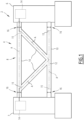
- an offshore platform 2 comprises a support structure 4 comprising a first structural element 6 and a second structural element 7 spaced from one another and a beam 8 extending between the two structural elements 6 for connecting them together.
- the support structure 4 is configured for supporting equipment of the offshore platform 2 and/or a top-side of the offshore platform 2.
- Each of the first structural element 6 and the second structural element 7 is for example a leg or a column or a pylon or another beam of the support structure 4, in particular a leg or a column or a pylon.
- Each of the first structural element 6 and the second structural element 7 is preferably made of metal.
- the support structure 4 defines for example a jacket structure in which the structural elements 6 define legs or columns or pylons of the support structure 4, each beam 8 connecting two such structural elements 6.
- the beam 8 is of tubular construction.
- the beam 8 is formed of several tubes 10 which are connected together. Each tube 10 is preferably made of metal.
- the tubes 10 of the beam 8 are preferably welded together. Each tube 10 extends preferably along a tube axis A.
- each tube 10 of the beam 8 is for example comprised between 1 meter and 6 meters, in particular between 2 meters and 5 meters.
- the beam 8 is preferably submersible.
- submersible it is meant that the beam 8 partly or completely immerged when the offshore platform is operated offshore.
- the support structure 4 comprises a tank 12 for storing a fluid, the tank 12 being delimited in at least two tubes 10 of the beam 8.
- the tank 12 is thus "integrated" in the beam 8.
- the fluid is for example a liquid or a gas, in particular a pressurized gas, for example pressurized air.
- the tubes 10 delimiting the tank 12 are connected together such that the individual internal volumes of said tubes 10 are connected and delimit a single common internal volume defining the tank 12.
- the tubes 10 delimiting the tank 12 are for example connected together via open welded connections.
- Two tubes 10 connected together and delimiting the tank 12 are connected to each other at a non-zero angle.
- the tube axes A of the two tubes 10 define a non-zero angle between them.
- the tank 12 is for example fluidly connected to fluid components 14 supported by the support structure 4, the fluid components 14 being located for example on the first structural element 6 and/or on the second structural element 7 and/or on pontoons of the offshore platform 2.
- Each fluid component 14 is configured to feed the tank 12 with fluid and/or to bed fed with fluid from the tank 12.
- Each fluid component 14 is for example a fluid circuit, a pipe, a pump, a valve, a pressure regulator, a flow rate regulator, a fluid reservoir, a ballast, a fluid intake or a fluid outtake.
- the tank 12 is for example delimited within the tubes 10 by internal partition walls 15 extending across said tubes 10.
- the internal partition walls 15 are preferably distant from the connections of the tubes 10 to the first and second structural elements 6, 7.
- the beam 8 comprises primary tubes 10, each primary tube 10 having at least one end connected to the first structural element 6 or to the second structural element 7.
- Each primary tube 10 has for example one end connected to the first structural element 6 and one end connected to the second structural element 7 or one end connected to one of the first and second structural elements 6, 7 and one end connected to another tube 10 of the beam 8.
- the beam 8 optionally comprises secondary tubes 10.
- the two ends of each secondary tube 10 are connected to other tubes 10 of the beam 8, each said other tube 10 being a primary tube 10 or another secondary tube 10.
- Such secondary tubes 10 are also designated as "braces”.
- the beam 8 is connected to the first and second structural elements 6, 7 via connections 16.
- Each connection 16 connects the end a primary tube 10 of the beam 8 to one of the first and second structural elements 6, 7.
- the tank 12 is advantageously fluidly connected to fluid components 14 via the connections 16 between the beam 8 and the first and second structural elements 6, 7.
- each connection 16 with the first structural element 6 is a bolted flange connection and/or each connection 16 with the second structural element 7 is a bolted flange connection.
- each connection 16 with the first structural element 6 is a bolted flange connection and each connection 16 with the second structural element 7 is a bolted flange connection.
- each connection 16 with the first structural element 6 is a bolted flange connection and each connection 16 with the second structural element 7 is a welded connection.
- each connection 16 with the first structural element 6 is a welded connection and each connection 16 with the second structural element 7 is a bolted flange connection.
- connection of the beam 8 with the first structural element 6 and/or with the second structural element 7 via bolted flange connections 16 allows manufacturing the support structure 4 as separate modules, which are then assembled via the bolted flange connection(s) 16.
- the beam 8 may have different arrangement of tubes 10, various number of connections 16 with each of the first and second structural elements 6, 7 and different arrangements of the tank 12 in the tubes 10 of the beam 8.
- a section of the tank 12 is delimited in at least one primary tube 10 of the beam 8. This allows an easy connection of the tank 12 to fluid equipment 14 via the connection of an end of the primary tube 10 with one of the first structural element 6 and the second structural element 7.
- the primary tube 10 delimiting the tank 12 has for example one end connected to the first structural element 6 and the other end connected to the second structural element 7 or has one end connected to the first structural element 6 and the other end connected to another tube 10, in particular another primary tube 10 or a secondary tube 10.
- the beam 8 comprises a primary tube 10 deprived of any section of the tank 12 extending in said primary tube 10.
- the beam 8 comprises a primary tube 10 having one end connected to the first structural element 6 and the other end connected to the second structural element 7, which is deprived of any section of the tank 12 extending in said primary tube 10. This allows using such a primary tube 10 as a pontoon for operators two walk inside the primary tube 10 moving between the first structural element 6 and the second structural element 7.
- the tank 12 is delimited in at least one secondary tube 10 of the beam 8.
- the tank 12 is delimited for example in one single secondary tube 10 or in two or more secondary tubes 10.
- the beam 8 is connected to the first structural element 6 by one single connection 16 or two connections 16 and/or the beam 8 is connected to the second structural element 7 by one single connection 16 or two connections 16.
- the beam 8 is for example connected to the first and second structural elements 6, 7 via two, three or four connections 16.
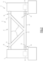
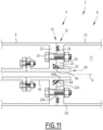
- the beam 8 comprises two primary tubes 10 which are parallel and preferably horizontal, each of said two primary tube 10 having one end connected to each of the first structural element 6 by a connection 16 and one end connected to the second structural element 7 by a connection 16.
- the beam also comprises at least one secondary tube 10, the secondary tube(s) connecting the two primary tubes 10 together.
- at least one or each secondary tube 10 extends between the two primary tubes 10 with having one end connected to one of the two primary tubes 10 and the other end connected to the other one of the two primary tubes 10.
- the two primary tubes 10 are for example positioned one above the other, thus defining a lower primary tube 10 and an upper primary tube 10.
- the tank 12 is delimited in at least one of the two primary tubes 10 and in at least one secondary tube 10.
- the tank 12 is for example delimited in one of the two primary tubes 10 and in at least one secondary tube 10 and the tank 12 is not delimited in the other one of the two primary tubes 10.
- the primary tube 10 free of any section of the tank 12 is preferably an upper primary tube 10.
- the beam 8 comprises for example two secondary tubes 10 each extending between the two primary tubes 10. At least one or each secondary tube 10 extends for example obliquely with respect to the primary tubes 10.
- the distance between the ends of the two secondary tubes 10 connected to one of the two primary tubes 10, in particular a lower primary tube 10 is for example strictly smaller than the distance between the ends of the two secondary tubes 10 connected to the other primary tubes 10, in particular an upper primary tube 10.
- the beam 8 advantageously comprises an upper and lower primary tubes 10, each having one end connected to the first structural element 6 via a connection 16 and one end connected the second structural element 7 via a connection 16 and two secondary tubes 10, each secondary tube 10 extending between the two primary tubes 10.
- a section of the tank 12 is delimited in the lower primary tube 10 and the tank 12 is not delimited in the upper primary tube 10.
- the tank 12 is also delimited in the two secondary tubes 10.
- the upper primary tube 10 can be used as a pontoon with avoiding the need for the operator to descend to the lower primary tube 10.
- a section of the tank 12 is delimited in the upper primary tube 10 and the tank 12 is not delimited in the lower primary tube 10.
- the tank 12 is for example connected to the first structural element 6 via the connection 16 between the upper primary tube 10 and the first structural element 6 and/or via the connection 16 between the lower primary tube 10 and the first structural element 6 and/or connected to the second structural element 7 via the connection 16 between the upper primary tube 10 and second structural element 7and/or via the connection 16 between the lower primary tube 10 and the second structural element 7.
- the tank 12 is for example fluidly connected to the first structural element 6 via the connection 16 between the upper primary tube 10 and the first structural element 6 and/or fluidly connected to the second structural element 7 via the connection 16 between the upper primary tube 10 and second structural element 7.
- the upper ends of the secondary tubes 10 are spaced apart and thus closer to the first structural element 6 and the second structural element 7, thus limiting the length of pipe necessary for making the fluid connection.
- the tank 12 is for example fluidly connected to the first and second structural elements 6, 7 via their connections 16 with the lower primary tube 10, without fluid connection between the tank 12 and the first and second structural elements 6, 7 via their connections with the upper primary tube 10.
- the tank 12 is for example fluidly connected to the first structural element 6 via its connection with lower primary tube 10 without fluid connection between the tank 12 and the first structural element 6 via its connection 16 with the upper primary tube 10 and fluidly connected to the second structural element 7 via its connection with the upper primary tube 10 without fluid connection between the tank 12 and the second structural element 7 via its connection with the lower primary tube 10.
- the tank 12 is for example fluidly connected to the first structural element 6 via its connection with upper primary tube 10 without fluid connection between the tank 12 and the first structural element 6 via its connection with the lower primary tube 10 and fluidly connected to the second structural element 7 via its connection with the lower primary tube 10 without fluid connection between the tank 12 and the second structural element 7 via its connection with the upper primary tube 10.
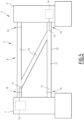
- the beam 8 may exhibits other shapes.
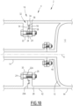
- the beam 8 differs from that of Figure 1 - 4 in that the beam 8 comprises one single secondary tube 10 extending obliquely between the two primary tubes 10.
- the tank 12 is delimited in the secondary tube 10 and at least one of the primary tube 10, for example only one of the two primary tubes 10, preferably the lower primary tube 10.
- the secondary tube 10 extends from the end of the lower primary tube 10 connected to the first structural element 6 to the end of the upper primary tube 10 connected to the second structural element 7.
- the tank 12 is for example fluidly connected to fluid components 14 via the lower connection 16 with the first structural element 6 and via the upper connection 16 with the second structural element 7.
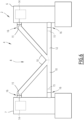
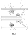
- the beam 8 differs from that of Figure 1 - 4 in that the beam 8 comprises a first primary tube 10 extending between the first and second structural elements 6, 7.
- the beam 8 further comprises a second primary tube 10 extending between the first primary tube 10 and the first structural element 6 and/or a third primary tube 10 extending between the first primary tube 10 and the second structural element 7.
- the beam 8 is connected to the first and second structural elements 6, 7 via three or four connections 16
- the tank 12 is for example delimited in two or three tubes 10 among the first primary tube 10, the second primary tube 10 and the third primary tube 10.
- the tank 12 is for example delimited in the first primary tube 10 and in the second primary tube 10 and/or the third primary tube 10.
- connection 16 is a welded connection or a bolted flange connection 16.
- connection 16 with the first structural element 6 is a bolted flange connection and/or each connection with the second structural element 7 is a bolted flange connection.
- each connection 16 between the beam 8 and the first and second structural element 6, 7 is a bolted flange connection 16.
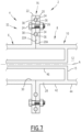
- the bolted flange connection 16 comprises a first flange 20 provided on the tube 10 and a second flange 22 provided on the structural element 6, the first flange 20 and the second flange 22 being bolted together.
- the first flange 20 and the second flange 22 are annular.
- the first flange 20 and the second flange 22 extend around a central axis A of the bolted flange connection 16.
- the first flange 20 has a front face 20A and the second flange 22 has a front face 22A.
- the front face 20A of the first flange 20 faces the front face 22A of the second flange 22.
- the first flange 20 and the second flange 22 are abutted axially one against the other and bolted one to the other via a plurality of bolts 24.
- the bolts 24 are distributed circumferentially on the first flange 20 and the second flange 22 around the central axis A.
- the bolts 24 are distributed around the central axis A along one or several imaginary circles.
- the bolted flange connection 16 comprise preferably more than two bolts 24.
- the number of bolts 24 is for example chosen as function of the diameter of the first and second flanges 20, 22.
- the first flange 20 is provided at an end 28 of the tube 10.
- the second flange 22 is provided for example on a connection opening 30 of the structural member 6.
- the end 28 of the tube 10 and the connection opening 30 are preferably coaxial and centered on the central axis A of the bolted flange connection 16.
- the end 28 of the tube 10 and the connection opening 30 are preferably of circular cross-section and of same diameter.
- the bolts 24 of the bolted flange connection 16 extend through the first flange 20 and the second flange 22 for fixing the first flange 20 and the second flange 22 together, each bolt 24 being for example engaged with a mating nut 26.
- the first flange 20 and the second flange 22 extend for example radially outwardly from the tube 10 and the connection opening 30, as illustrated on Figure 7 , or radially inwardly from the tube 10 and the connection opening 30.
- the first flange 20 and the second flange 22 are for example in direct contact with each other, in particular in metal-to-metal contact with each other. More specifically the front face 20A of the first flange 20 and the front face 22A of the second flange 22 are in direct contact with each other. This ensure a reliable mechanical connection of the tube 10 and the structural element 6 via the bolted flange connection 16.
- the bolted flange connection 16 comprises a sealing assembly 32 configured for sealing the bolted flange connection 16 in a watertight manner.
- the sealing assembly 32 seals the junction between the tube 10 and the structural element 6.
- the sealing assembly 32 is configured for preventing liquid and/or gas to enter and/or exit the support structure 4 via the bolted flange connection 16.
- the sealing assembly 32 is advantageously configured for preventing water to enter the support structure 4 via the bolted flange connection 16 and/or for preventing liquid and/or gas contained in the tank 12, in particular pressurized gas contained in the tank 12 to exit the support structure 4 via the bolted flange connection 16.
- the sealing assembly 32 comprises one or several sealing members, including for example one or several annular seals, one or several sealing washers and/or one or several sealing sleeves.
- the sealing assembly 32 comprises for example at least one annular seal 34 interposed between the first flange 20 and the second flange 22 with being partly received in a first groove 36 formed in the first flange 20 and partly received in a second groove 38 formed in the second flange 22 or entirely received in a first groove 36 formed in the first flange 20 and in contact with the second flange 10 or entirely received in a second groove 38 formed in the second flange 22 and in contact with the first flange 20.
- Each annular seal 34 is made for example of natural or synthetic rubber or elastomer.
- the sealing assembly 32 comprises at least one annular seal 34, each annular seal 34 of the sealing assembly 32 being partly received in a first groove 36 formed in the first flange 20 and partly received in a second groove 38 formed in the second flange 22.
- the sealing assembly 32 is preferably configured such that the first flange 20 and the second flange 22 are in contact with each other via their respective front faces 20A, 22A.
- Each annular seal 34 received in a first groove 36 and/or a second groove 38 allows a contact between the first flange 20 and the second flange 22 with an efficient sealing.
- the sealing assembly 32 is configured such that each annular seal 34 is compressed between the first flange 20 and the second flange 22.
- each annular seal 34 as well as the size and the shape of each groove receiving the annular seal 20 (first groove 36 and/or second groove 38) are configured for a compression of the annular seal 34 between the first flange 20 and the second flange 22.
- Each annular seal 34 has for example a circular profile, an elliptical profile, a square profile, a rectangular profile or a trapezoidal profile in a free state of the annular seal 34, i.e. before compression between the first flange 20 and the second flange 22.
- the sealing assembly 32 comprises for example two annular seals 34 arranged concentrically with being centered on the central axis A.
- the sealing assembly 32 comprises for example one annular seal 34 located radially outwards relative to the bolts 24 and/or one annular seal 34 located radially inwards relative to the bolts 24.
- the cross-section of a groove formed in the front face 20A of the first flange 20 or in the front face 22A of the second flange 22 for receiving at least partially or entirely an annular seal 34 may exhibit various profiles, such as a semi-circular profile, a square profile, a rectangular profile or a trapezoidal profile.
- the tube 10 delimits the tank 12.
- the tube 10 comprises advantageously a partition wall 15 extending across the tube 10 for delimiting the tank 12 in a section of the tube 10, the partition wall 15 being located along the tube 10 at a distance from the first flange 20.
- the tube 10 comprises a connection section 42 extending between the end 28 and the partition wall 15 and tank section 44 extending from the partition wall 15 opposite the end 28.
- the provision of the partition wall 15 at a distance from the end 28 of the tube 10 connected to the structural element 6 by the bolted flange connection 16 improves the reliability as the bolted flange connection 16 which is not in contact with the fluid contained in the reservoir 30 and not subjected to the pressure of this fluid.
- the support structure 4 comprises advantageously a connection pipe 46 for fluidly connecting the tank 12 to fluid components 14 (not shown on Figure 7 ).
- the tank 12 is connected to said fluid components 14 via the bolted flange connection 16.
- connection pipe 46 extends from the partition wall 15 towards the structural element 6 for connecting the tank 12 to the fluid components 14.
- connection pipe 46 is connected to the fluid components 14 for example by a bolted connection or a welded connection or any other type of suitable connection.
- the bolted flange connection 16 is not limited to the examples and variants discussed in reference to Figure 7 .
- first flange 20 and the second flange 22 protrude radially outwardly from the tube 10 and the connection opening 30 of structural element 6.
- the bolted flange connection 16 of Figure 8 differs from that of Figure 7 in that the first flange 20 and the second flange 22 protrude radially inwardly from the tube 10 and the connection opening 30 of structural element 6.
- This configuration offers the advantage that the bolts 24 are located inside the bolted flange connection 16 and are thus protected from the outside elements, namely from the water.
- the arrangements of the bolts 24 of the bolted flange connection 16 may be different to that of the bolted flange connection 16 of Figure 7 .
- the bolts 24 of the bolted flange connection 16 are arranged in one row of bolts 24 extending along an imaginary circle centered on the central axis A or several rows of bolts 24, each row extending along an imaginary circle centered on the central axis A, the rows being arranged concentrically around the central axis A.
- the bolted flange connection 16 of Figure 8 differs from that of Figure 7 in that the bolted flange connection 16 comprises two rows of bolts 24 extending concentrically around the central axis A.
- the sealing assembly 32 of the bolted flange connection 16 of the bolted flange of Figure 7 comprises one or several annular seals 34, each annular seal 34 being received in a first groove 36 and a second groove 38.
- the bolted flange connection 16 comprises a sealing washer 48 which is interposed between the first flange 20 and the second flange 22, preferably such that the first flange 20 and the second flange 22 bear against each other via the sealing washer 48 without contacting each other.
- the sealing washer 48 is preferably flat shaped and extends radially relative to the central axis A.
- the bolts 14 of the bolted flange connection 16 extend for example through the sealing washer 48, via holes provided in the sealing washer 48.
- the sealing washer 48 is for example made of metal, preferably a metal resisting to corrosion, in particular stainless steel or bronze, such as a bronze containing copper and in addition tin, zinc and/or aluminum.
- the sealing assembly 32 comprises a sealing sleeve 50 arranged around the bolted flange connection 16.
- the sealing sleeve 50 extends on the external surface of the tube 10 and on an external surface of the structural member 6 with covering the junction between the tube 10 and the structural member 6.
- the sealing sleeve 50 is for example made of a flexible material.
- the sealing sleeve 50 made of a flexible material in conformable to the bolted flange connection 16.
- the sealing sleeve 50 is for example wrapped around the bolted flange connection 16.
- the sealing sleeve 50 if for example made of one or several layers each made of rubber or made of a composite material comprising a matrix and reinforcement fibers embedded in the matrix.
- the sealing sleeve 50 is for example obtained by wrapping the product Guard-Wrap TM of the company TRENTON around the bolted flange connection 16.
- the product Guard-Wrap TM comprises of a spunbonded polyester mat, saturated with microcrystalline wax that is laminated to a polyester film which is coated with microcrystalline wax.
- the sealing assembly 32 comprises an annular seal 34 that is entirely received in a groove provided in one of the first flange 20 with making a seal contact with the second flange 22 and/or an annular seal 34 that is entirely received in a groove provided in the second flange 22 with making a seal contact with the first flange 20
- the sealing assembly 32 comprises an annular seal 34 which is entirely received in a second groove 38 formed in front face 22A of the second flange 22 with being in sealing contact with the front face 20A of the first flange 20A when the bolts 24 of the bolted flange connection 16 are tightened.
- the sealing assembly 32 comprises an annular protrusion 54 formed on one among the first flange 20 and the second flange 22, the annular protrusion 54 engaging into a annular groove 56 formed in the other among the first flange 20 and the second flange 22, at least one annular seal 34 being optionally received in the annular groove 56 and compressed by the annular protrusion 50.
- annular seals 34 are for example received in the annular groove 56, each annular seal 34 being compressed by the annular protrusion 54 onto respective sealing seats 58, the two sealing seats 58 being preferably inclined relative to the central axis A and/or inclined one relative to the other.
- the sealing assembly 32 comprises for example an annular protrusion 54 provided one the second flange 22 and an annular groove 56 provided on the first flange 20, two annular seals 34 being received in the annular groove 56 with being compressed in the annular groove 56 against respective sealing seats 58 inclined relative to the central axis A and inclined one relative to the other.
- Each sealing seat 58 is for example frustoconical and centered on the central axis A, one sealing seat 58 facing radially outwardly and the other sealing seat 58 facing radially inwardly.
- the half cone angle of each sealing seat 58 is for example comprises between 30° and 60° and in particular substantially equal to 45°.
- the sealing assembly 32 comprises for example an annular seal 34 which is partly or entirely received in a groove formed in front face 20A, 22A of one of the first flange 20 and the second flange 22, the groove being shape such that the annular seal 34 is locked in the groove.
- the groove is for example shaped such that an opening of the groove is narrower that a bottom of the groove.
- the groove exhibits for example a trapezoidal cross-section, with the two parallel sides of the trapezoidal cross-section defining the bottom and the opening of the first groove and the converging sides of the trapezoidal cross-section defining the sides of the first groove.
- the sealing assembly 32 comprises for example an annular seal 34 which is entirely received in a first groove 36 formed in front face 20A of the first flange 20 with being in sealing contact with the front face 22A of the second flange 22.
- the first groove 38 exhibits a trapezoidal cross-section, with the two parallel sides of the trapezoidal cross-section defining the bottom and the opening of the first groove 38 and the converging sides of the trapezoidal cross-section defining the sides of the first groove 38.
- sealing of the bolted flange connection 16 is achieved through application of a sealing coating (not shown) such as painting, preferably a resin, such as polyester or epoxy resins, optionally reinforced with glass and/or carbon fiber, either in the form of bulk or woven or non-woven fabric.
- a sealing coating such as painting, preferably a resin, such as polyester or epoxy resins, optionally reinforced with glass and/or carbon fiber, either in the form of bulk or woven or non-woven fabric.
- the sealing coating is applied for example on the first flange 20, on the second flange 22, at the junction between the tube 10 and the structural element 6 and/or on the bolts 24.
- the support structure 4 comprises a sealing arrangement 60 for creating a watertight seal between a connection pipe 46 for the fluid connection of the tank 12 and one among the first flange 20 and the second flange 22.
- the sealing arrangement 60 comprises for example a sealing ring 62 wedged between an outer surface 46A of the connection pipe 46 and a sealing seat 64 of one among the first flange 20 and the second flange 22.
- the sealing ring 62 comprises for example a cylindrical inner face 66 in contact with an outer face of the connection pipe 46 and/or a frustoconical outer surface 68 in contact with the sealing seat 64.
- connection pipe 46 is attached to the second flange 22, the sealing arrangement 60 being provided between the connection pipe 46 and the first flange 20 with the sealing ring 62 being fitted on the connection pipe 46 and wedged between the connection pipe 46 and the first flange 20.
- an offshore platform support structure 4 which is a compact and lightweight naval construction with simple and robust design along with ease of installation, operation and maintenance.
- the tank 12 delimited inside at least two tubes 10 of the beam 8 allows providing the tank 12 integrated within the beam 8 with ease of installation, operation, inspection and maintenance.
- the tank 12 delimited inside at least two tubes 10 of the beam 8 allows providing a tanl 12 with a high storage volume.
- a tank 12 with higher storage volume allows storing a same quantity of pressurized gas as a tank 12 of lower storage capacity but at a lower storage pressure. This allows using more economical and/or reliable fluid components 14. In particular, it allows using a less powerful pump for filing the tank 12.
- the tank 12 delimited inside at least two tubes 10 increases the fluid connection possibilities between the tank 12 on the one hand and the first and second structural members 6, 7 on the other hand.
- the provision of at least three connections 16 between the beam 8 and the first and second structural element 6, 7 provides a support structure 4 which is reliable.
- a sealing assembly 32 on a bolted flange connection 16 avoids fluid ingress in the support structure 4 and/or fluid leakage out of the support structure 4, in particular when the support structure 4 is provided with the integrated tank 12.
- the invention is suitable for use with any kind of offshore platform such as jack-up rig offshore platform, conventional bottom-fixed offshore platform, tension leg offshore platform, spar offshore platform or gravitary offshore platform.
Landscapes
- Engineering & Computer Science (AREA)
- General Engineering & Computer Science (AREA)
- Mechanical Engineering (AREA)
- Civil Engineering (AREA)
- Structural Engineering (AREA)
- Architecture (AREA)
- Chemical & Material Sciences (AREA)
- Combustion & Propulsion (AREA)
- Ocean & Marine Engineering (AREA)
- Filling Or Discharging Of Gas Storage Vessels (AREA)
Priority Applications (4)
| Application Number | Priority Date | Filing Date | Title |
|---|---|---|---|
| EP23305790.0A EP4464845A1 (de) | 2023-05-17 | 2023-05-17 | Strukturanordnung mit einem träger mit einem integrierten, in zwei röhren des trägers begrenzten tank |
| PCT/EP2024/063687 WO2024236172A1 (en) | 2023-05-17 | 2024-05-17 | Structure assembly comprising a beam with an integrated tank delimited in two tubes of the beam |
| EP24727357.6A EP4713531A1 (de) | 2023-05-17 | 2024-05-17 | Strukturanordnung mit einem träger mit einem integrierten, in zwei röhren des trägers begrenzten tank |
| KR1020257041867A KR20260011170A (ko) | 2023-05-17 | 2024-05-17 | 빔의 두 개의 튜브 내에 구획된 통합 탱크를 가지는 빔을 포함하는 구조체 어셈블리 |
Applications Claiming Priority (1)
| Application Number | Priority Date | Filing Date | Title |
|---|---|---|---|
| EP23305790.0A EP4464845A1 (de) | 2023-05-17 | 2023-05-17 | Strukturanordnung mit einem träger mit einem integrierten, in zwei röhren des trägers begrenzten tank |
Publications (1)
| Publication Number | Publication Date |
|---|---|
| EP4464845A1 true EP4464845A1 (de) | 2024-11-20 |
Family
ID=86688757
Family Applications (2)
| Application Number | Title | Priority Date | Filing Date |
|---|---|---|---|
| EP23305790.0A Withdrawn EP4464845A1 (de) | 2023-05-17 | 2023-05-17 | Strukturanordnung mit einem träger mit einem integrierten, in zwei röhren des trägers begrenzten tank |
| EP24727357.6A Pending EP4713531A1 (de) | 2023-05-17 | 2024-05-17 | Strukturanordnung mit einem träger mit einem integrierten, in zwei röhren des trägers begrenzten tank |
Family Applications After (1)
| Application Number | Title | Priority Date | Filing Date |
|---|---|---|---|
| EP24727357.6A Pending EP4713531A1 (de) | 2023-05-17 | 2024-05-17 | Strukturanordnung mit einem träger mit einem integrierten, in zwei röhren des trägers begrenzten tank |
Country Status (3)
| Country | Link |
|---|---|
| EP (2) | EP4464845A1 (de) |
| KR (1) | KR20260011170A (de) |
| WO (1) | WO2024236172A1 (de) |
Citations (4)
| Publication number | Priority date | Publication date | Assignee | Title |
|---|---|---|---|---|
| US20120328437A1 (en) * | 2009-12-07 | 2012-12-27 | Hexicon Ab | Floating energy producing plant |
| DE102018103894A1 (de) * | 2018-02-21 | 2019-08-22 | Max Bögl Wind AG | Schwimmendes Fundament für eine Off-Shore-Anlage sowie Off-Shore-Anlage mit einem schwimmenden Fundament |
| US20230049381A1 (en) * | 2020-01-23 | 2023-02-16 | Ocergy, Inc. | Floating marine platform |
| EP4257474A1 (de) * | 2022-04-08 | 2023-10-11 | Ocergy, Inc. | Schwimmende meeresplattform und deren herstellung |
-
2023
- 2023-05-17 EP EP23305790.0A patent/EP4464845A1/de not_active Withdrawn
-
2024
- 2024-05-17 EP EP24727357.6A patent/EP4713531A1/de active Pending
- 2024-05-17 KR KR1020257041867A patent/KR20260011170A/ko active Pending
- 2024-05-17 WO PCT/EP2024/063687 patent/WO2024236172A1/en not_active Ceased
Patent Citations (4)
| Publication number | Priority date | Publication date | Assignee | Title |
|---|---|---|---|---|
| US20120328437A1 (en) * | 2009-12-07 | 2012-12-27 | Hexicon Ab | Floating energy producing plant |
| DE102018103894A1 (de) * | 2018-02-21 | 2019-08-22 | Max Bögl Wind AG | Schwimmendes Fundament für eine Off-Shore-Anlage sowie Off-Shore-Anlage mit einem schwimmenden Fundament |
| US20230049381A1 (en) * | 2020-01-23 | 2023-02-16 | Ocergy, Inc. | Floating marine platform |
| EP4257474A1 (de) * | 2022-04-08 | 2023-10-11 | Ocergy, Inc. | Schwimmende meeresplattform und deren herstellung |
Also Published As
| Publication number | Publication date |
|---|---|
| WO2024236172A1 (en) | 2024-11-21 |
| KR20260011170A (ko) | 2026-01-22 |
| EP4713531A1 (de) | 2026-03-25 |
Similar Documents
| Publication | Publication Date | Title |
|---|---|---|
| US7097387B2 (en) | Engineered material buoyancy system and device | |
| US7757621B2 (en) | Vessel for transport of compressed natural gas | |
| EP4464845A1 (de) | Strukturanordnung mit einem träger mit einem integrierten, in zwei röhren des trägers begrenzten tank | |
| US20210285204A1 (en) | Frame Structure for a Floating Installation | |
| US4208055A (en) | Method and device for sealing the place of penetration of a pipeline in the wall of a submerged structure | |
| EP4464591A1 (de) | Schwimmende offshore-plattform mit einem in zwei röhren des trägers begrenzten integrierten tank | |
| US3803855A (en) | Submerged oil storage tank | |
| EP4464592A1 (de) | Schwimmende offshore-plattform mit integriertem tank und verschraubter flanschverbindung | |
| EP4464844A1 (de) | Strukturelle anordnung mit einem träger mit integriertem tank und einer verschraubten flanschverbindung | |
| DE102010049224B4 (de) | Einrichtung zum Auffangen und Ableiten von aus einem Gewässergrund austretenden Flüssigkeiten und/oder Gasen | |
| US3145538A (en) | Underwater storage apparatus | |
| US4685409A (en) | Device for the storing of oil | |
| US4425054A (en) | Marine platform adapted to facilitate the detection of possible cracks | |
| NO20241019A1 (en) | Frame for use subsea | |
| KR20190096179A (ko) | 해상 발전구조물의 부유시스템 | |
| JP5703209B2 (ja) | エネルギー回収チャンバー | |
| RU2123145C1 (ru) | Воздухоотводчик | |
| GB2617439A (en) | Frame for use subsea | |
| CA2857910A1 (en) | Cellular tendons for tlp | |
| RU2292510C1 (ru) | Гибкая труба и концевое соединение гибкой трубы | |
| CN214609400U (zh) | 一种地埋抗浮无拉筋立式罐体 | |
| GB2398762A (en) | Buoyancy module for riser pipes | |
| CN210342086U (zh) | 一种双管网叠压供水机构 | |
| CN121778325A (zh) | 一种用于水下返排液等废液存储的模块化柔性容器系统 | |
| FI13445Y1 (fi) | Ponttoonilautta nestesäiliöitä varten |
Legal Events
| Date | Code | Title | Description |
|---|---|---|---|
| PUAI | Public reference made under article 153(3) epc to a published international application that has entered the european phase |
Free format text: ORIGINAL CODE: 0009012 |
|
| STAA | Information on the status of an ep patent application or granted ep patent |
Free format text: STATUS: THE APPLICATION HAS BEEN PUBLISHED |
|
| AK | Designated contracting states |
Kind code of ref document: A1 Designated state(s): AL AT BE BG CH CY CZ DE DK EE ES FI FR GB GR HR HU IE IS IT LI LT LU LV MC ME MK MT NL NO PL PT RO RS SE SI SK SM TR |
|
| STAA | Information on the status of an ep patent application or granted ep patent |
Free format text: STATUS: THE APPLICATION IS DEEMED TO BE WITHDRAWN |
|
| 18D | Application deemed to be withdrawn |
Effective date: 20250521 |