EP4464844A1 - Strukturelle anordnung mit einem träger mit integriertem tank und einer verschraubten flanschverbindung - Google Patents
Strukturelle anordnung mit einem träger mit integriertem tank und einer verschraubten flanschverbindung Download PDFInfo
- Publication number
- EP4464844A1 EP4464844A1 EP23305792.6A EP23305792A EP4464844A1 EP 4464844 A1 EP4464844 A1 EP 4464844A1 EP 23305792 A EP23305792 A EP 23305792A EP 4464844 A1 EP4464844 A1 EP 4464844A1
- Authority
- EP
- European Patent Office
- Prior art keywords
- flange
- bolted
- sealing
- tube
- connection
- Prior art date
- Legal status (The legal status is an assumption and is not a legal conclusion. Google has not performed a legal analysis and makes no representation as to the accuracy of the status listed.)
- Withdrawn
Links
Images


Classifications
-
- E—FIXED CONSTRUCTIONS
- E02—HYDRAULIC ENGINEERING; FOUNDATIONS; SOIL SHIFTING
- E02B—HYDRAULIC ENGINEERING
- E02B17/00—Artificial islands mounted on piles or like supports, e.g. platforms on raisable legs or offshore constructions; Construction methods therefor
- E02B17/0004—Nodal points
-
- B—PERFORMING OPERATIONS; TRANSPORTING
- B63—SHIPS OR OTHER WATERBORNE VESSELS; RELATED EQUIPMENT
- B63B—SHIPS OR OTHER WATERBORNE VESSELS; EQUIPMENT FOR SHIPPING
- B63B77/00—Transporting or installing offshore structures on site using buoyancy forces, e.g. using semi-submersible barges, ballasting the structure or transporting of oil-and-gas platforms
-
- E—FIXED CONSTRUCTIONS
- E02—HYDRAULIC ENGINEERING; FOUNDATIONS; SOIL SHIFTING
- E02B—HYDRAULIC ENGINEERING
- E02B17/00—Artificial islands mounted on piles or like supports, e.g. platforms on raisable legs or offshore constructions; Construction methods therefor
- E02B17/02—Artificial islands mounted on piles or like supports, e.g. platforms on raisable legs or offshore constructions; Construction methods therefor placed by lowering the supporting construction to the bottom, e.g. with subsequent fixing thereto
- E02B17/027—Artificial islands mounted on piles or like supports, e.g. platforms on raisable legs or offshore constructions; Construction methods therefor placed by lowering the supporting construction to the bottom, e.g. with subsequent fixing thereto steel structures
Definitions
- the present invention relates to the technical field of offshore platforms, notably offshore platforms for a hydrocarbon exploration and/or production.
- a bottom-fixed offshore platform comprises a support structure which is configured for supporting the equipment of the offshore platform.
- the support structure comprises for example a plurality of metal structural elements welded together, the structural elements comprising for example legs, columns or pylons, and beams extending transversely between the legs, columns or pylons for maintaining a transverse spacing between the legs, columns or pylons.
- One of the aims of the invention is to propose an offshore platform support structure which is a compact and lightweight naval construction with simple and robust design along with ease of installation, operation and maintenance.
- the invention proposes a structural assembly for a support structure, the structural assembly comprising a beam formed of one or several tubes, the beam comprising a tank for storing fluid integrated inside the beam, the tank being delimited inside one or several tubes of the beam, and a least one bolted flange connection, each bolted flange connection connecting an end of one tube of the beam to another structural element of the support structure, each bolted flange connection comprising a first flange and a second flange bolted together with bolts, wherein at least one bolted flange connection is sealed with a sealing assembly comprising at least one sealing member configured for sealing the bolted flange connection.
- the tank integrated in the beam provides an efficient way to increase the fluid storage capacity of the offshore platform with limiting the cost of construction of the offshore platform.
- the provision of a bolted flange connection between a tube of the beam and another structural element of the support structure allows obtaining a compact and lightweight naval construction that is very easy to install.
- the number of welding operations for assembling the support structure can be limited.
- the inspection and maintenance are easy, in particular the inspection and maintenance of the tank and fluid components associated to the tank.
- the support structure comprises one or several of the following features, taken individually or according to any technically feasible combination:
- the invention also relates to an offshore platform, in particular bottom-fixed offshore platform, comprising a support structure, the support structure comprising at least one structural assembly as defined above.
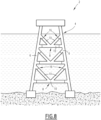
- the offshore platform 2 illustrated on Figure 1 comprises a support structure 4 comprising two structural elements 6 spaced from one another and a beam 8 extending between the two structural elements 6 for connecting them together.
- the support structure 4 is configured for supporting equipment of the offshore platform 2 and/or a top-side of the offshore platform 2.
- Each structural element 6 of the support structure 4 is for example a leg or a column or a pylon or even another beam of the support structure 4.
- Each structural element 6 is preferably made of metal.
- the support structure 4 defines for example a jacket structure in which the structural elements 6 define legs or columns or pylons of the support structure 4, each beam 8 connecting two such structural elements 6.
- the beam 8 is of tubular construction.
- the beam 8 is formed of one tube 10 or several tubes 10 which are connected together, preferably welded together.
- Each tube 10 is preferably made of metal.
- each tube 10 of the beam 8 is for example comprised between 1 meter and 6 meters, in particular between 2 meters and 5 meters.
- the beam 8 is preferably submersible.
- submersible it is meant that the beam 8 is partly or completely immerged when the offshore platform is operated offshore.
- the support structure 4 comprises a tank 12 for storing a fluid, the tank 12 being delimited in one or several tubes 10 of the beam 8.
- the tank 12 is thus "integrated" in the beam 8.
- the fluid is for example a liquid or a gas, in particular a pressurized gas, for example pressurized air.
- the tank 12 is delimited for example in one single tube 10 of the beam 8 or in several tubes 10 of the beam 8. In the latter case, said tubes 10 of the beam 8 are connected together such that the individual internal volumes of said tubes 10 delimit a single common internal volume defining the tank 12.
- the tubes 10 of the beam 8 which delimit the tank 12 are for example welded together via open welded connections.
- the tank 12 is for example fluidly connected to fluid components 14 supported by the support structure 4, the fluid components 14 being located for example on the structural elements 6 connected by the beam 8 or on pontoons of the offshore platform 2.
- the fluid components 14 comprises for example one or several fluid circuits, one or several pipes, one or several reservoirs and/or one or several passive or active fluid control devices, such as one or several valves, one or several pressure regulators and/or one or several flow rate regulators.
- the beam 8 is connected to the structural elements 6 via bolted flange connections 16.
- Each bolted flange connection 16 connects the end of one tube 10 of the beam 8 to one of the two structural elements 6.
- the beam 8 has at least one tube 10 connected to each one of the two structural elements 6.
- the beam 8 is for example connected to one structural element 6 via one tube 10, two tubes 10 or more than two tubes 10 and connected to the other structural element 6 via one tube 10, two tubes 10 or more than two tubes 10.
- the beam 8 is connected to at least one of the two structural elements 6 by one or several bolted flange connections 16, each bolted flange connection 16 connecting a respective tube 10 to one of the two structural elements 6.
- the beam 8 is for example connected to each one of the two structural elements 6 by one or several bolted flange connections 16, each bolted flange connection 16 connecting a respective end of a tube 10 to one of the structural elements 6.
- the beam 8 is connected to one structural element 6 by one or several bolted flange connections 16, each bolted flange connection 16 connecting a respective end of a tube 10 to said structural element 6, and connected to the other structural element 6 by one or several welded connections, each welded connection connecting a respective end of a tube 10 to said other structural element 6.
- the beam 8 comprises for example at least one tube 10 which extends between the two structural elements 6 with having one end connected to one structural element 6 via a bolted flange connection 16 and another end connected to the other structural element 6 via a bolted flange connection 16 or a welded connection.
- the beam 8 may comprise different number of tubes 10 and exhibit different shapes as a function of the arrangement of the tubes 10 of the beam 8.
- the support structure 4 comprises one or several separate beams 10 extending between the two structural elements 6 and connecting the two structural elements 6.
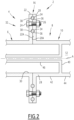
- the bolted flange connections 16 are similar. Examples of structural assemblies comprising a beam 10 connected to a structural member 6 of a support structure 4 via a bolted flange connection 16 are illustrated on Figures 2 - 6 on which corresponding or similar elements are designated with the same numeral reference.
- the bolted flange connection 16 comprises a first flange 20 provided on the tube 10 and a second flange 22 provided on the structural element 6, the first flange 20 and the second flange 22 being bolted together.
- the first flange 20 and the second flange 22 are annular.
- the first flange 20 and the second flange 22 extend around a central axis A of the bolted flange connection 16.
- the first flange 20 has a front face 20A and the second flange 22 has a front face 22A.
- the front face 20A of the first flange 20 faces the front face 22A of the second flange 22.
- the first flange 20 and the second flange 22 are abutted axially one against the other and bolted one to the other via a plurality of bolts 24.
- the bolts 24 are distributed circumferentially on the first flange 20 and the second flange 22 around the central axis A.
- the bolts 24 are distributed around the central axis A along one or several imaginary circles.
- the bolted flange connection 16 comprise preferably more than two bolts 24.
- the number of bolts 24 is for example chosen as function of the diameter of the first and second flanges 20, 22.
- the first flange 20 is provided at an end 28 of the tube 10.
- the second flange 22 is provided for example on a connection opening 30 of the structural member 6.
- the end 28 of the tube 10 and the connection opening 30 are preferably coaxial and centered on the central axis A of the bolted flange connection 16.
- the end 28 of the tube 10 and the connection opening 30 are preferably of circular cross-section and of same diameter.
- the bolts 24 of the bolted flange connection 16 extend through the first flange 20 and the second flange 22 for fixing the first flange 20 and the second flange 22 together, each bolt 24 being for example engaged with a mating nut 26.
- the first flange 20 and the second flange 22 extend for example radially outwardly from the tube 10 and the connection opening 30, as illustrated on Figure 2 , or radially inwardly from the tube 10 and the connection opening 30.
- the first flange 20 and the second flange 22 are for example in direct contact with each other, in particular in metal-to-metal contact with each other. More specifically the front face 20A of the first flange 20 and the front face 22A of the second flange 22 are in direct contact with each other. This ensure a reliable mechanical connection of the tube 10 and the structural element 6 via the bolted flange connection 16.
- the bolted flange connection 16 comprises a sealing assembly 32 configured for sealing the bolted flange connection 16.
- the sealing assembly 32 seals the junction between the tube 10 and the structural element 6.
- the sealing assembly 32 is configured for preventing liquid and/or gas to enter and/or exit the support structure 4 via the bolted flange connection 16.
- the sealing assembly 32 is advantageously configured for preventing water to enter the support structure 4 via the bolted flange connection 16 and/or for preventing liquid and/or gas contained in the tank 12, in particular pressurized gas contained in the tank 12 to exit the support structure 4 via the bolted flange connection 16..
- the sealing assembly 32 comprises one or several sealing members, including for example one or several annular seals, one or several sealing washers, one or several sealing rings and/or one or several sealing sleeves.
- the sealing assembly 32 comprises for example at least one annular seal 34 interposed between the first flange 20 and the second flange 22 with being partly received in a first groove 36 formed in the first flange 20 and partly received in a second groove 38 formed in the second flange 22 or entirely received in a first groove 36 formed in the first flange 20 and in contact with the second flange 22 or entirely received in a second groove 38 formed in the second flange 22 and in contact with the first flange 20.
- Each annular seal 34 is made for example of natural or synthetic rubber or elastomer.
- the sealing assembly 32 comprises at least one annular seal 34, each annular seal 34 of the sealing assembly 32 being partly received in a first groove 36 formed in the first flange 20 and partly received in a second groove 38 formed in the second flange 22.
- the sealing assembly 32 is preferably configured such that the first flange 20 and the second flange 22 are in contact with each other via their respective front faces 20A, 22A.
- Each annular seal 34 received in a first groove 36 and/or a second groove 38 allows a contact between the first flange 20 and the second flange 22 with an efficient sealing.
- the sealing assembly 32 is configured such that each annular seal 34 is compressed between the first flange 20 and the second flange 22.
- each annular seal 34 as well as the size and the shape of each groove receiving the annular seal 20 (first groove 36 and/or second groove 38) are configured for a compression of the annular seal 34 between the first flange 20 and the second flange 22.
- Each annular seal 34 has for example a circular profile, an elliptical profile, a square profile, a rectangular profile or a trapezoidal profile in a free state of the annular seal 34, i.e. before compression between the first flange 20 and the second flange 22.
- the sealing assembly 32 comprises for example two annular seals 34 arranged concentrically with being centered on the central axis A.
- the sealing assembly 32 comprises for example one annular seal 34 located radially outwards relative to the bolts 24 and/or one annular seal 34 located radially inwards relative to the bolts 24.
- the cross-section of a groove formed in the front face 20A of the first flange 20 or in the front face 22A of the second flange 22 for receiving at least partially or entirely an annular seal 34 may exhibit various profiles, such as a semi-circular profile, a square profile, a rectangular profile or a trapezoidal profile.
- the tube 10 delimits the tank 12.
- the tube 10 comprises advantageously a partition wall 40 extending across the tube 10 for delimiting the tank 12 in a section of the tube 10, the partition wall 40 being located along the tube 10 at a distance from the first flange 20.
- the tube 10 comprises a connection section 42 extending between the end 28 and the partition wall 40 and tank section 44 extending from the partition wall 40 opposite the end 28.
- the provision of the partition wall 40 at a distance from the end 28 of the tube 10 connected to the structural element 6 by the bolted flange connection 16 improves the reliability as the bolted flange connection 16 which is not in contact with the fluid contained in the reservoir 30 and not subjected to the pressure of this fluid.
- the support structure 4 comprises advantageously a connection pipe 46 for fluidly connecting the tank 12 to fluid components 14 (not shown on Figure 2 ).
- the tank 12 is connected to said fluid components 14 via the bolted flange connection 16.
- connection pipe 46 extends from the partition wall 40 towards the structural element 6 for connecting the tank 12 to the fluid components 14.
- connection pipe 46 is connected to the fluid components 14 for example by a bolted connection or a welded connection or any other type of suitable connection.
- the bolted flange connection 16 is not limited to the examples and variants discussed in reference to Figure 2 .
- first flange 20 and the second flange 22 protrude radially outwardly from the tube 10 and the connection opening 30 of structural element 6.
- the bolted flange connection 16 of Figure 3 differs from that of Figure 2 in that the first flange 20 and the second flange 22 protrude radially inwardly from the tube 10 and the connection opening 30 of structural element 6.
- This configuration offers the advantage that the bolts 24 are located inside the bolted flange connection 16 and are thus protected from the outside elements, namely from the water.
- the arrangements of the bolts 24 of the bolted flange connection 16 may be different to that of the bolted flange connection 16 of Figure 2 .
- the bolts 24 of the bolted flange connection 16 are arranged in one row of bolts 24 extending along an imaginary circle centered on the central axis A or several rows of bolts 24, each row extending along an imaginary circle centered on the central axis A, the rows being arranged concentrically around the central axis A.
- the bolted flange connection 16 of Figure 3 differs from that of Figure 2 in that the bolted flange connection 16 comprises two rows of bolts 24 extending concentrically around the central axis A.
- the sealing assembly 32 of the bolted flange connection 16 of the bolted flange of Figure 2 comprises one or several annular seals 34, each annular seal 34 being received in a first groove 36 and a second groove 38.
- the bolted flange connection 16 comprises a sealing washer 48 which is interposed between the first flange 20 and the second flange 22 such that the first flange 20 and the second flange 22 bear against each other via the sealing washer 48 without contacting each other.
- the sealing washer 48 is preferably flat shaped and extends radially relative to the central axis A.
- the bolts 14 of the bolted flange connection 16 extend for example through the sealing washer 48, via holes provided in the sealing washer 48.
- the sealing washer 48 is for example made of metal, preferably a metal resisting to corrosion, in particular stainless steel or bronze, such as a bronze containing copper and in addition tin, zinc and/or aluminum.
- the sealing assembly 32 comprises a sealing sleeve 50 arranged around the bolted flange connection 16.
- the sealing sleeve 50 extends on the external surface of the tube 10 and on an external surface of the structural member 6 with covering the junction between the tube 10 and the structural member 6.
- the sealing sleeve 50 is for example made of a flexible material.
- the sealing sleeve 50 made of a flexible material in conformable to the bolted flange connection 16.
- the sealing sleave 50 is for example wraped around the bolted flange connection 16.
- the sealing sleeve 50 if for example made of one or several layers each made of rubber or made of a composite material comprising a matrix and reinforcement fibers embedded in the matrix.
- the sealing sleeve 50 is for example obtained by wrapping the product Guard-Wrap TM of the company TRENTON around the bolted flange connection 16.
- the product Guard-Wrap TM comprises of a spunbonded polyester mat, saturated with microcrystalline wax that is laminated to a polyester film which is coated with microcrystalline wax.
- the sealing assembly 32 comprises an annular seal 34 that is entirely received in a groove provided one the first flange 20 with making a seal contact with the second flange 22 and/or an annular seal 34 that is entirely received in a groove provided in the second flange 22 with making a seal contact with the first flange 20
- the sealing assembly 32 comprises an annular seal 34 which is entirely received in a second groove 38 formed in front face 22A of the second flange 22 with being in sealing contact with the front face 20A of the first flange 20A when the bolts 24 of the bolted flange connection 16 are tightened.
- the sealing assembly 32 comprises an annular protrusion 54 formed on one among the first flange 20 and the second flange 22, the annular protrusion 54 engaging into a annular groove 52 formed in the other among the first flange 20 and the second flange 22, at least one annular seal 34 being optionally received in the annular groove 56 and compressed by the annular protrusion 50.
- annular seals 34 are for example received in the annular groove 52, each annular seal 34 being compressed by the annular protrusion 54 onto respective sealing seats 58, the two sealing seats 58 being preferably inclined relative to the central axis A and/or inclined one relative to the other.
- the sealing assembly 32 comprises for example an annular protrusion 54 provided one the second flange 22 and an annular groove 52 provided on the first flange 20, two annular seals 34 being received in the annular groove 56 with being compressed in the annular groove 56 against respective sealing seats 58 inclined relative to the central axis A and inclined one relative to the other.
- Each sealing seat 58 is for example frustoconical and centered on the central axis A, one sealing seat 58 facing radially outwardly and the other sealing seat 58 facing radially inwardly.
- the half cone angle of each sealing seat 58 is for example comprises between 30° and 60° and in particular substantially equal to 45°.
- the sealing assembly 32 comprises for example an annular seal 34 which is partly or entirely received in a groove formed in the front face 20A, 22A of one of the first flange 20 and the second flange 22, the groove being shape such that the annular seal 34 is locked in the groove.
- the groove is for example shaped such that an opening of the groove is narrower that a bottom of the groove.
- the groove exhibits for example a trapezoidal cross-section, with the two parallel sides of the trapezoidal cross-section defining the bottom and the opening of the first groove and the converging sides of the trapezoidal cross-section defining the sides of the first groove.
- the sealing assembly 32 comprises for example an annular seal 34 which is entirely received in a first groove 36 formed in the front face 20A of the first flange 20 with being in sealing contact with the front face 22A of the second flange 22.
- the first groove 38 exhibits a trapezoidal cross-section, with the two parallel sides of the trapezoidal cross-section defining the bottom and the opening of the first groove 38 and the converging sides of the trapezoidal cross-section defining the sides of the first groove 38.
- sealing of the bolted flange connection 16 is achieved through application of a sealing coating (not shown) such as painting, preferably a resin, such as polyester or epoxy resins, optionally reinforced with glass and/or carbon fiber, either in the form of bulk or woven or non-woven fabric.
- a sealing coating such as painting, preferably a resin, such as polyester or epoxy resins, optionally reinforced with glass and/or carbon fiber, either in the form of bulk or woven or non-woven fabric.
- the sealing coating is applied for example on the first flange 20, on the second flange 22, at the junction between the tube 10 and the structural element 6 and/or on the bolts 24.
- the sealing assembly 32 comprises a sealing arrangement 60 for creating a seal between a connection pipe 46 for the fluid connection of the tank 12 and one among the first flange 20 and the second flange 22.
- the sealing arrangement 60 comprises for example a sealing ring 62 wedged between an outer surface 46A of the connection pipe 46 and a sealing seat 64 of one among the first flange 20 and the second flange 22.
- the sealing ring 62 comprises for example a cylindrical inner face 66 in contact with an outer face of the connection pipe 46 and/or a frustoconical outer surface 68 in contact with the sealing seat 64.
- connection pipe 46 is attached to the second flange 22, the sealing arrangement 60 being provided between the connection pipe 46 and the first flange 20 with the sealing ring 64 being fitted on the connection pipe 46 and wedged between the connection pipe 46 and the first flange 20.
- the beam 8 comprises one single tube 10 having two ends each connected to a respective structural element 6.
- the beam 8 may comprise different number of tubes 10 and exhibit different shapes as a function of the arrangement of the tubes 10 of the beam 8
- a support structure 4 comprises two structural members 6, formed e.g. as legs or columns or pylons connected by one or several beams 8, each beam 8 comprising four tubes 10, each tube 10 extending between a central connector to one structural element 6, two tubes 10 being connected to one structural element 6 and two tubes 10 being connected to the other structural element 6.
- the beam 8 exhibits substantially the shape of a "X".
- a support structure 4 comprises two structural members 6, formed e.g. as legs or columns or pylons connected by one or several beams 8, each beam 8 comprising one first tube 10 extending between the two structural elements 6 and two second tubes 10, each second tube 10 extending between an intermediate section of the first tube 10 and a respective structural element 6.
- the beam 8 exhibits substantially the shape of a "K".
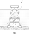
- a support structure 4 comprises two structural members 6, formed e.g. as legs or columns or pylons, connected by one or several beams 8, each beam 8 comprising two parallel first tubes 10, each first tube 10 extending between the two structural elements 6 and one second tube 10 extending obliquely between the two first tube 10 with being welded to the first tubes 10.
- the beam 8 exhibits substantially the shape of a "Z".
- each beam 8 comprises a first tube 10 extending between the two structural elements 6 and a second tube 10 extending between an intermediate section of the first tube 10 and one of the two structural element 6.
- the beam 8 exhibits a "Y" shape.
- each beam 8 is for example connected to each structural element 6 via one or several bolted flange connections 16, each bolted flange connection 16 connecting the end of one respective tube 10 to one of the two structural elements 6.
- each beam 8 is connected to one structural element 6 by one or several bolted flange connections 16, each bolted flange connection 16 connecting a respective end of a tube 10 to said structural element 6, and connected to the other structural element 6 by one or several welded connections, each welded connection connecting a respective end of a tube 10 to said other structural element 6.
- a beam 8 of tubular construction of any shape such as a beam 8 with a single tube 10, a beam 8 with the shape of a "X”, a beam 8 with the shape of a "Y” or a beam 8 with a the shape of a "K”.
- an offshore platform 2 comprising a support structure 4 which is a compact and lightweight naval construction with simple and robust design along with ease of inspection, maintenance and installation thanks to a tank 12 integrated in one or several tubes 10 of a beam 8 of tubular construction extending between two structural elements 6 with being connected to at least one of the two structural elements 6 with one or several bolted flange connection 16, each bolted flange connection 16 connecting a tube 10 to a structural element 6.
- the tank 12 is suitable for storage of liquid or gas, such as natural gas or natural condensates or air.
- the bolted flange connections 16 provide for an easy erection of the support structure 4 with making the fluid connections of the tank 12 with the fluid components 14 easy to implement, to inspect and to maintain.
- Sealing the bolted flange connection 16 avoids fluid ingress in the support structure 4, with limiting in particular fluid ingress in the tank 12, and/or fluid leak out from the support structure 4, in particular fluid leak from the tank 12.
- first and second flanges 20, 22 avoid a direct contact of the first and second flanges 20, 22 flanges and the bolts 26 with the surrounding air or water.
- a partition wall 40 provided in a tube 10 at a distance from a bolted flange connection 16 for delimiting a tank 12 avoids the bolted flange connection 16 being subjected to the mechanical stress due to the fluid contained in the tank, in particular when the fluid is a pressurized fluid, and avoids a direct contact between the bolted flange connection 16 and the fluid contained in the tank 12.
- the support structure 4 is suitable for any kind of offshore platform, in particular bottom-fixed offshore platform such as jack-up rig platform, conventional bottom-fixed platform, tension leg platform, spar platform or gravitary platform.
- bottom-fixed offshore platform such as jack-up rig platform, conventional bottom-fixed platform, tension leg platform, spar platform or gravitary platform.
Landscapes
- Engineering & Computer Science (AREA)
- General Engineering & Computer Science (AREA)
- Mechanical Engineering (AREA)
- Civil Engineering (AREA)
- Structural Engineering (AREA)
- Transportation (AREA)
- Chemical & Material Sciences (AREA)
- Combustion & Propulsion (AREA)
- Ocean & Marine Engineering (AREA)
- Pressure Vessels And Lids Thereof (AREA)
- Flanged Joints, Insulating Joints, And Other Joints (AREA)
Priority Applications (4)
| Application Number | Priority Date | Filing Date | Title |
|---|---|---|---|
| EP23305792.6A EP4464844A1 (de) | 2023-05-17 | 2023-05-17 | Strukturelle anordnung mit einem träger mit integriertem tank und einer verschraubten flanschverbindung |
| EP24727304.8A EP4713530A1 (de) | 2023-05-17 | 2024-05-16 | Strukturelle anordnung mit einem träger mit integriertem tank und einer verschraubten flanschverbindung |
| KR1020257041786A KR20260011168A (ko) | 2023-05-17 | 2024-05-16 | 통합된 탱크가 있는 빔 및 볼트체결 플랜지 연결부를 구조체 어셈블리 |
| PCT/EP2024/063511 WO2024236104A1 (en) | 2023-05-17 | 2024-05-16 | Structural assembly comprising a beam with an integrated tank and a bolted flange connection |
Applications Claiming Priority (1)
| Application Number | Priority Date | Filing Date | Title |
|---|---|---|---|
| EP23305792.6A EP4464844A1 (de) | 2023-05-17 | 2023-05-17 | Strukturelle anordnung mit einem träger mit integriertem tank und einer verschraubten flanschverbindung |
Publications (1)
| Publication Number | Publication Date |
|---|---|
| EP4464844A1 true EP4464844A1 (de) | 2024-11-20 |
Family
ID=86688438
Family Applications (2)
| Application Number | Title | Priority Date | Filing Date |
|---|---|---|---|
| EP23305792.6A Withdrawn EP4464844A1 (de) | 2023-05-17 | 2023-05-17 | Strukturelle anordnung mit einem träger mit integriertem tank und einer verschraubten flanschverbindung |
| EP24727304.8A Pending EP4713530A1 (de) | 2023-05-17 | 2024-05-16 | Strukturelle anordnung mit einem träger mit integriertem tank und einer verschraubten flanschverbindung |
Family Applications After (1)
| Application Number | Title | Priority Date | Filing Date |
|---|---|---|---|
| EP24727304.8A Pending EP4713530A1 (de) | 2023-05-17 | 2024-05-16 | Strukturelle anordnung mit einem träger mit integriertem tank und einer verschraubten flanschverbindung |
Country Status (3)
| Country | Link |
|---|---|
| EP (2) | EP4464844A1 (de) |
| KR (1) | KR20260011168A (de) |
| WO (1) | WO2024236104A1 (de) |
Citations (4)
| Publication number | Priority date | Publication date | Assignee | Title |
|---|---|---|---|---|
| US20110155038A1 (en) * | 2008-01-09 | 2011-06-30 | Jaehnig Jens | Floating foundation supporting framework with buoyancy components, having an open-relief design |
| KR101643853B1 (ko) * | 2015-10-06 | 2016-08-10 | 아주지오텍(주) | 수중 강관파일의 클램프형 드라이탱크 |
| DE102018103894A1 (de) * | 2018-02-21 | 2019-08-22 | Max Bögl Wind AG | Schwimmendes Fundament für eine Off-Shore-Anlage sowie Off-Shore-Anlage mit einem schwimmenden Fundament |
| US20230049381A1 (en) * | 2020-01-23 | 2023-02-16 | Ocergy, Inc. | Floating marine platform |
-
2023
- 2023-05-17 EP EP23305792.6A patent/EP4464844A1/de not_active Withdrawn
-
2024
- 2024-05-16 EP EP24727304.8A patent/EP4713530A1/de active Pending
- 2024-05-16 KR KR1020257041786A patent/KR20260011168A/ko active Pending
- 2024-05-16 WO PCT/EP2024/063511 patent/WO2024236104A1/en not_active Ceased
Patent Citations (4)
| Publication number | Priority date | Publication date | Assignee | Title |
|---|---|---|---|---|
| US20110155038A1 (en) * | 2008-01-09 | 2011-06-30 | Jaehnig Jens | Floating foundation supporting framework with buoyancy components, having an open-relief design |
| KR101643853B1 (ko) * | 2015-10-06 | 2016-08-10 | 아주지오텍(주) | 수중 강관파일의 클램프형 드라이탱크 |
| DE102018103894A1 (de) * | 2018-02-21 | 2019-08-22 | Max Bögl Wind AG | Schwimmendes Fundament für eine Off-Shore-Anlage sowie Off-Shore-Anlage mit einem schwimmenden Fundament |
| US20230049381A1 (en) * | 2020-01-23 | 2023-02-16 | Ocergy, Inc. | Floating marine platform |
Also Published As
| Publication number | Publication date |
|---|---|
| KR20260011168A (ko) | 2026-01-22 |
| EP4713530A1 (de) | 2026-03-25 |
| WO2024236104A1 (en) | 2024-11-21 |
Similar Documents
| Publication | Publication Date | Title |
|---|---|---|
| US7097387B2 (en) | Engineered material buoyancy system and device | |
| KR102293217B1 (ko) | 절연 장치 및 방법 | |
| US4208055A (en) | Method and device for sealing the place of penetration of a pipeline in the wall of a submerged structure | |
| EP3874101B1 (de) | Flanschelement, flanschverbindung mit solchen flanschelementen und turmkonstruktion | |
| EP4464844A1 (de) | Strukturelle anordnung mit einem träger mit integriertem tank und einer verschraubten flanschverbindung | |
| CN101208239B (zh) | 压缩天然气运输船 | |
| KR101049055B1 (ko) | 내압형 볼/슬립 복합 이음관 | |
| EP4464592A1 (de) | Schwimmende offshore-plattform mit integriertem tank und verschraubter flanschverbindung | |
| US3803855A (en) | Submerged oil storage tank | |
| EP4464845A1 (de) | Strukturanordnung mit einem träger mit einem integrierten, in zwei röhren des trägers begrenzten tank | |
| EP4464591A1 (de) | Schwimmende offshore-plattform mit einem in zwei röhren des trägers begrenzten integrierten tank | |
| US4425054A (en) | Marine platform adapted to facilitate the detection of possible cracks | |
| US20250230730A1 (en) | Frame for use subsea | |
| JP2018127260A (ja) | タンクの地下設置構造 | |
| US12553209B2 (en) | Buoyancy resistance pile for subsea structure installation | |
| GB2617439A (en) | Frame for use subsea | |
| US20150037103A1 (en) | Cellular tendons for tlp | |
| US3606397A (en) | Fluid swivel with load bearing shaft | |
| RU2292510C1 (ru) | Гибкая труба и концевое соединение гибкой трубы | |
| CN112112926A (zh) | 一种高稳定性的减震型复合管 | |
| CN223909059U (zh) | 一种水利工程管道装置 | |
| CN101655161B (zh) | 一种清空阀 | |
| CN201547259U (zh) | 一种清空阀 | |
| GB2398762A (en) | Buoyancy module for riser pipes | |
| CN213145738U (zh) | 一种多波随动平衡缓冲橡胶膨胀节 |
Legal Events
| Date | Code | Title | Description |
|---|---|---|---|
| PUAI | Public reference made under article 153(3) epc to a published international application that has entered the european phase |
Free format text: ORIGINAL CODE: 0009012 |
|
| STAA | Information on the status of an ep patent application or granted ep patent |
Free format text: STATUS: THE APPLICATION HAS BEEN PUBLISHED |
|
| AK | Designated contracting states |
Kind code of ref document: A1 Designated state(s): AL AT BE BG CH CY CZ DE DK EE ES FI FR GB GR HR HU IE IS IT LI LT LU LV MC ME MK MT NL NO PL PT RO RS SE SI SK SM TR |
|
| STAA | Information on the status of an ep patent application or granted ep patent |
Free format text: STATUS: THE APPLICATION IS DEEMED TO BE WITHDRAWN |
|
| 18D | Application deemed to be withdrawn |
Effective date: 20250521 |