EP4464594A1 - Floating structure - Google Patents
Floating structure Download PDFInfo
- Publication number
- EP4464594A1 EP4464594A1 EP22928871.7A EP22928871A EP4464594A1 EP 4464594 A1 EP4464594 A1 EP 4464594A1 EP 22928871 A EP22928871 A EP 22928871A EP 4464594 A1 EP4464594 A1 EP 4464594A1
- Authority
- EP
- European Patent Office
- Prior art keywords
- ammonia
- equipment
- fuel
- cover
- ammonia fuel
- Prior art date
- Legal status (The legal status is an assumption and is not a legal conclusion. Google has not performed a legal analysis and makes no representation as to the accuracy of the status listed.)
- Pending
Links
Images


Classifications
-
- B—PERFORMING OPERATIONS; TRANSPORTING
- B63—SHIPS OR OTHER WATERBORNE VESSELS; RELATED EQUIPMENT
- B63B—SHIPS OR OTHER WATERBORNE VESSELS; EQUIPMENT FOR SHIPPING
- B63B17/00—Vessels parts, details, or accessories, not otherwise provided for
- B63B17/0027—Tanks for fuel or the like ; Accessories therefor, e.g. tank filler caps
- B63B17/0036—Arrangements for minimizing pollution by accidents
-
- B—PERFORMING OPERATIONS; TRANSPORTING
- B63—SHIPS OR OTHER WATERBORNE VESSELS; RELATED EQUIPMENT
- B63B—SHIPS OR OTHER WATERBORNE VESSELS; EQUIPMENT FOR SHIPPING
- B63B17/00—Vessels parts, details, or accessories, not otherwise provided for
-
- B—PERFORMING OPERATIONS; TRANSPORTING
- B63—SHIPS OR OTHER WATERBORNE VESSELS; RELATED EQUIPMENT
- B63B—SHIPS OR OTHER WATERBORNE VESSELS; EQUIPMENT FOR SHIPPING
- B63B43/00—Improving safety of vessels, e.g. damage control, not otherwise provided for
-
- B—PERFORMING OPERATIONS; TRANSPORTING
- B63—SHIPS OR OTHER WATERBORNE VESSELS; RELATED EQUIPMENT
- B63H—MARINE PROPULSION OR STEERING
- B63H21/00—Use of propulsion power plant or units on vessels
- B63H21/38—Apparatus or methods specially adapted for use on marine vessels, for handling power plant or unit liquids, e.g. lubricants, coolants, fuels or the like
-
- B—PERFORMING OPERATIONS; TRANSPORTING
- B63—SHIPS OR OTHER WATERBORNE VESSELS; RELATED EQUIPMENT
- B63J—AUXILIARIES ON VESSELS
- B63J2/00—Arrangements of ventilation, heating, cooling, or air-conditioning
- B63J2/02—Ventilation; Air-conditioning
- B63J2/06—Ventilation; Air-conditioning of engine rooms
-
- B—PERFORMING OPERATIONS; TRANSPORTING
- B63—SHIPS OR OTHER WATERBORNE VESSELS; RELATED EQUIPMENT
- B63J—AUXILIARIES ON VESSELS
- B63J4/00—Arrangements of installations for treating ballast water, waste water, sewage, sludge, or refuse, or for preventing environmental pollution not otherwise provided for
-
- F—MECHANICAL ENGINEERING; LIGHTING; HEATING; WEAPONS; BLASTING
- F02—COMBUSTION ENGINES; HOT-GAS OR COMBUSTION-PRODUCT ENGINE PLANTS
- F02M—SUPPLYING COMBUSTION ENGINES IN GENERAL WITH COMBUSTIBLE MIXTURES OR CONSTITUENTS THEREOF
- F02M21/00—Apparatus for supplying engines with non-liquid fuels, e.g. gaseous fuels stored in liquid form
- F02M21/02—Apparatus for supplying engines with non-liquid fuels, e.g. gaseous fuels stored in liquid form for gaseous fuels
- F02M21/0203—Apparatus for supplying engines with non-liquid fuels, e.g. gaseous fuels stored in liquid form for gaseous fuels characterised by the type of gaseous fuel
- F02M21/0206—Non-hydrocarbon fuels, e.g. hydrogen, ammonia or carbon monoxide
-
- F—MECHANICAL ENGINEERING; LIGHTING; HEATING; WEAPONS; BLASTING
- F02—COMBUSTION ENGINES; HOT-GAS OR COMBUSTION-PRODUCT ENGINE PLANTS
- F02M—SUPPLYING COMBUSTION ENGINES IN GENERAL WITH COMBUSTIBLE MIXTURES OR CONSTITUENTS THEREOF
- F02M21/00—Apparatus for supplying engines with non-liquid fuels, e.g. gaseous fuels stored in liquid form
- F02M21/02—Apparatus for supplying engines with non-liquid fuels, e.g. gaseous fuels stored in liquid form for gaseous fuels
- F02M21/0218—Details on the gaseous fuel supply system, e.g. tanks, valves, pipes, pumps, rails, injectors or mixers
- F02M21/0221—Fuel storage reservoirs, e.g. cryogenic tanks
- F02M21/0224—Secondary gaseous fuel storages
-
- B—PERFORMING OPERATIONS; TRANSPORTING
- B63—SHIPS OR OTHER WATERBORNE VESSELS; RELATED EQUIPMENT
- B63B—SHIPS OR OTHER WATERBORNE VESSELS; EQUIPMENT FOR SHIPPING
- B63B2241/00—Design characteristics
- B63B2241/20—Designs or arrangements for particular purposes not otherwise provided for in this class
- B63B2241/22—Designs or arrangements for particular purposes not otherwise provided for in this class for providing redundancy to equipment or functionality of a vessel, e.g. for steering
-
- Y—GENERAL TAGGING OF NEW TECHNOLOGICAL DEVELOPMENTS; GENERAL TAGGING OF CROSS-SECTIONAL TECHNOLOGIES SPANNING OVER SEVERAL SECTIONS OF THE IPC; TECHNICAL SUBJECTS COVERED BY FORMER USPC CROSS-REFERENCE ART COLLECTIONS [XRACs] AND DIGESTS
- Y02—TECHNOLOGIES OR APPLICATIONS FOR MITIGATION OR ADAPTATION AGAINST CLIMATE CHANGE
- Y02T—CLIMATE CHANGE MITIGATION TECHNOLOGIES RELATED TO TRANSPORTATION
- Y02T70/00—Maritime or waterways transport
- Y02T70/50—Measures to reduce greenhouse gas emissions related to the propulsion system
Definitions
- the present disclosure relates to a floating structure.
- PTL 1 discloses a configuration in which an ammonia storage tank, an ammonia injection nozzle, and an ammonia supply pipe are configured to have a duplicate structure so that ammonia does not leak into a ship.
- the ammonia storage tank storing the ammonia is accommodated in an ammonia storage tank chamber.
- a base end portion of the ammonia injection nozzle for jetting the ammonia stored in the ammonia storage tank is accommodated in an ammonia injection nozzle chamber.
- An ammonia supply pipe that guides the ammonia stored in the ammonia storage tank to the ammonia injection nozzle is accommodated in a duct.
- the present disclosure has been made to solve the above problems, and an object of the present disclosure is to provide a floating structure capable of suppressing diffusion of ammonia into a floating main structure while suppressing an increase in complexity of a structure and an increase in cost.
- the combustion device 8 is a device that generates thermal energy by combusting fuel and is provided inside the floating main structure 3.
- Examples of the combustion device 8 include an internal combustion engine used in a main engine for propulsion of the floating structure 1, an internal combustion engine used in a power generation facility that supplies power into the ship, and a boiler that generates steam as a working fluid.
- as fuel ammonia and another fuel such as light oil different from ammonia can be used by switching.
- the plurality of equipment units 10A are provided in the floating main structure 3. In the present embodiment, for example, two equipment units 10A are disposed (refer to Fig. 2 ), but three or more equipment units 10A may be disposed. In the present embodiment, the plurality of equipment units 10A are disposed in the same compartment K in the floating main structure 3.
- the compartment K of the present embodiment is exemplified as an engine room 9.
- the plurality of equipment units 10A may be disposed in another chamber in the floating main structure 3 that is different from the engine room 9.
- the compartment in which the plurality of equipment units 10A are disposed may be provided on the upper deck 7.
- the ammonia fuel tank 16 is a tank that stores liquid ammonia (in other words, liquefied ammonia).
- the ammonia fuel tank 16 is installed on the upper deck 7 closer to a stem 3b side than the superstructure 4. Disposition of the ammonia fuel tank 16 is an example and is not limited to the disposition on the upper deck 7 closer to the stern 3b side than the superstructure 4.
- the ammonia fuel tank 16 of the present embodiment stores liquefied ammonia as fuel for the combustion device 8.
- each of the equipment units 10A includes ammonia fuel-handling equipment 11 and a housing 20A that accommodates the ammonia fuel-handling equipment 11.
- the pipe system 30 connects the fuel supply device 12 of each of the equipment units 10A and the combustion device 8.
- the pipe system 30 supplies the liquefied ammonia of the temporary storage tank 14 to the combustion device 8, and returns the surplus ammonia remaining unused as fuel in the combustion device 8 to the temporary storage tank 14.
- the pipe system 30 of the present embodiment includes a pipe 31 and a valve 32.
- the pipe 31 connects the fuel supply device 12 and the combustion device 8 to each other, and guides the liquefied ammonia from the fuel supply device 12 to the combustion device 8.
- the valve 32 is provided in the pipe 31 and is capable of adjusting the flow rate of the liquefied ammonia flowing through the pipe 31.
- the housing 20A accommodates the ammonia fuel-handling equipment 11 in each of the equipment units 10A.
- the housing 20A includes a base 21, a frame 22, and a cover 25.
- the base 21 is placed on the floor of the compartment K (engine room 9) where the equipment unit 10A is installed.
- the base 21 of the present embodiment is detachably fixed to the floor of the compartment K.
- the base 21 supports the ammonia fuel-handling equipment 11 from below.
- the base 21 has, for example, a rectangular shape in a plan view when viewed from above.
- the equipment unit 10A is disposed in a posture in which a long side direction D1 of the base 21 coincides with the bow-stem direction FA.
- the equipment unit 10A of the present embodiment is disposed such that a short side direction D2 of the base 21 coincides with the ship width direction.
- the base 21 is formed of, for example, a steel frame material or the like.
- the bottom surface or the upper surface of the base 21 may be closed by, for example, an iron plate or the like.
- the posture of the equipment unit 10A is not limited to the above posture.
- the frame 22 is provided on the base 21.
- the frame 22 includes, for example, four columns 23 that stand upward from four corners of the base 21, and an upper beam material 24 that connects upper end portions of the columns 23 to each other.
- the frame 22 is formed to surround the ammonia fuel-handling equipment 11.
- the equipment unit 10A of the present embodiment is accommodated in a so-called container-shaped housing 20A including the base 21, the frame 22, and the cover 25. More specifically, the equipment unit 10A has an outer shape equivalent to that of the ISO standard marine container, with the base 21, the frame 22, and the cover 25.
- the equipment unit 10A of the present embodiment further includes a water sprinkling device 50 and a ventilation device 53.
- the water sprinkling device 50 sprinkles water in the housing 20A in a case where the leakage of the ammonia fuel occurs in the housing 20A.
- the water sprinkling device 50 includes a water supply pipe 51 and a water sprinkling nozzle 52.
- the water supply pipe 51 supplies water from the outside of the housing 20A.
- the water sprinkling nozzle 52 sprinkles the water supplied through the water supply pipe 51 into the housing 20A.
- a plurality of the water sprinkling nozzles 52 may be provided in the upper portion in the housing 20A.
- the ventilation device 53 discharges the vaporized ammonia to the outside of the housing 20A in a case where the leakage of the ammonia fuel occurs in the housing 20A.
- the ventilation device 53 includes a duct 54 and a fan 55.
- One end of the duct 54 is connected to a through-hole (not shown) formed in the cover 25 of the housing 20A.
- the other end of the duct 54 is connected to an exhaust duct (not shown) or a detoxification facility (not shown) provided in the floating main structure 3.
- the fan 55 discharges the ammonia (gas) that has occurred inside the housing 20A to the outside through the duct 54.
- the ventilation device 53 may be either a positive pressure type or a negative pressure type but is preferably a negative pressure type from the viewpoint of suppressing leakage of ammonia to the surroundings.
- the equipment unit 10A may be provided with the water recovery unit (not shown) that recovers the water sprinkled by the water sprinkling device 50.
- the water recovery unit discharges, for example, the water sprinkled by the water sprinkling device 50 and stored in the bottom portion in the housing 20A to the outside of the housing 20A.
- the water recovery unit discharges the recovered water to the outside of the floating main structure 3.
- the plurality of equipment units 10A including the ammonia fuel-handling equipment 11 are provided in the floating main structure 3.
- Each of the equipment units 10A includes the cover 25 that covers the ammonia fuel-handling equipment 11. Accordingly, even when the ammonia fuel leaks from the ammonia fuel-handling equipment 11, the leaked ammonia fuel is retained inside the cover 25. Accordingly, the diffusion of the ammonia fuel to the outside of the cover 25 is suppressed.
- the cover 25 may be provided for each of the ammonia fuel-handling equipment 11, and the diffusion of the ammonia fuel can be suppressed by a simple configuration. Therefore, it is possible to suppress diffusion of ammonia into the floating main structure 3 while suppressing an increase in complexity of a structure and an increase in cost.
- the equipment unit 10A further includes the water sprinkling device 50.
- the ammonia fuel leaks from the ammonia fuel-handling equipment 11 into the cover 25
- the ammonia is absorbed by the water by the water sprinkling device 50 sprinkling the water into the space in the cover 25. Therefore, it is possible to effectively suppress the diffusion of the ammonia into the floating main structure 3.
- the volume inside the housing 20A is small as compared with a case where the water sprinkling is performed in the entire compartment K, the amount of water sprinkling can be reduced, and the ammonia can be quickly absorbed.
- the equipment unit 10A since the equipment unit 10A includes the ventilation device 53, in a case where the ammonia fuel leaks from the ammonia fuel-handling equipment 11 into the cover 25, the ammonia in the cover 25 can be discharged to the outside by the ventilation device 53. In this case, as compared with a case where ventilation is performed in the entire compartment K, the volume inside the housing 20A is small, and ventilation can be quickly performed. In addition, since the ventilation device 53 is provided in each of the equipment units 10A, the capacity of the fan 55 can be reduced, and thus the cost can be reduced.
- the plurality of equipment units 10A are disposed in the same compartment K in the floating main structure 3. Accordingly, in a case where the plurality of equipment units 10A are disposed in the same compartment K in the floating main structure 3, even when the leakage of the ammonia fuel occurs in some equipment units 10A of the plurality of equipment units 10A, the leakage of the ammonia fuel to the outside of the cover 25 of the equipment units 10A in which the leakage of the ammonia fuel has occurred is suppressed. Therefore, the influence on other equipment units 10A can be suppressed, and the operation of the ammonia fuel-handling equipment 11 in other equipment units 10A can also be continued.
- At least a part of the cover 25 is formed to be capable of transmitting light from the outside to the inside of the cover 25. Therefore, the operation of the ammonia fuel equipment, the presence or absence of leakage of the ammonia fuel, and the like inside the cover 25 can be visually confirmed from the outside of the cover 25.
- the floating structure 1 of the above embodiment includes the base 21 and the frame 22 formed to surround the ammonia fuel-handling equipment 11, and the cover 25 is attached to the frame 22. Therefore, the equipment unit 10A can be transported and installed in the floating main structure 3 in the same manner as a container or the like.
- the housing 20A has a size that can be transported by a vehicle such as a trailer or a truck, the housing 20A can be easily transported to the outside of the floating structure 1 when the housing 20A is installed. Further, by making the housing 20A have the same strength as or higher strength than that of a marine container such as a so-called ISO container, so-called stacking in which a plurality of the housings 20A are stacked and disposed up and down can also be performed.
- the ammonia fuel-handling equipment 11 includes the fuel supply device 12 capable of supplying the ammonia fuel, in a case where the ammonia fuel leaks in the fuel supply device 12 provided in the floating main structure 3, it is possible to suppress the diffusion of the ammonia into the floating main structure 3.
- Fig. 4 is a plan view showing an equipment unit provided in the floating structure in a second embodiment of the present disclosure.
- an equipment unit 10B of the floating structure 1 of the second embodiment includes the ammonia fuel-handling equipment 11 and a housing 20B.
- An opening 26 that allows the inside and the outside of the cover 25 to communicate with each other is formed in the cover 25 of the housing 20B.
- the compartment K (engine room 9) in which a plurality of the housings 20B are disposed is provided with an in-compartment water sprinkling device 60.
- the in-compartment water sprinkling device 60 sprinkles water in the compartment K in a case where the leakage of the ammonia fuel occurs in at least one of the plurality of housings 20B.
- the in-compartment water sprinkling device 60 includes a water supply pipe 61 and a water sprinkling nozzle 62.
- the water supply pipe 61 supplies water from the outside of the compartment K.
- the water sprinkling nozzle 62 sprinkles the water supplied through the water supply pipe 61 into the compartment K.
- a plurality of the water sprinkling nozzles 62 may be provided in the upper portion in the housing 20B in the compartment K.
- the cover 25 includes the opening 26, and the in-compartment water sprinkling device 60 is provided in the compartment K in which the equipment unit 10B is disposed. Therefore, in a case where the ammonia fuel leaks from the ammonia fuel-handling equipment 11, the ammonia fuel is discharged to the space outside the cover 25 through the opening 26. The ammonia is absorbed by the water sprinkling via the in-compartment water sprinkling device 60 with respect to the discharged ammonia fuel.
- each equipment unit 10B includes the cover 25. Therefore, in a case where water is sprinkled from the in-compartment water sprinkling device 60, it is possible to suppress the ammonia fuel-handling equipment 11 of each equipment unit 10B from being wet with water.
- the water sprinkling device 50 is provided in the housing 20B.
- the water sprinkling device 50 provided in the housing 20B may be omitted.
- the ventilation device 53 may be omitted.
- the same configuration as the ventilation device 53 may be provided in the compartment K.
- Fig. 5 is a plan view showing an equipment unit provided in the floating structure in a third embodiment of the present disclosure.
- the floating structure 1 of the third embodiment includes a connection unit 70 disposed between the plurality of equipment units 10A.
- the plurality of equipment units 10A are disposed on the floor surface of the compartment K (engine room 9) at intervals in the horizontal direction.
- Fig. 5 a case where the plurality of equipment units 10A are disposed at intervals in the short side direction D2 of the equipment unit 10A having a rectangular shape in a plan view is exemplified.
- the plurality of equipment units 10A may be disposed at intervals in the long side direction D1 of the equipment unit 10A having a rectangular shape in a plan view.
- the connection unit 70 can be stacked and disposed on the equipment unit 10A up and down, which is so-called stacking.
- the connection unit 70 includes a connection pipe 71.
- the connection pipe 71 connects the ammonia fuel-handling equipment 11 of the adjacent equipment units 10A with the connection unit 70 interposed therebetween.
- the connection unit 70 includes a housing 80 that covers the connection pipe 71.
- the housing 80 includes the base 21 and the frame 22, which are the same as those of the equipment unit 10A, and a pipe cover 75.
- the pipe cover 75 is attached to the frame 22 and is disposed to cover the upper portion and the side of the frame 22 between the plurality of equipment units 10A.
- connection pipe 71 and the pipe cover 75 covering the connection pipe 71 are disposed between the plurality of equipment units 10A. Therefore, even in a case where the ammonia fuel leaks from the connection pipe 71 provided to cross the plurality of equipment units 10A, the diffusion of the ammonia into the floating main structure 3 can be suppressed.
- connection unit 70 including the connection pipe 71 and the pipe cover 75 is disposed between the plurality of equipment units 10A shown in the first embodiment.
- equipment unit 10B shown in the second embodiment may be disposed instead of the equipment unit 10A.
- the floating structure 1 is a ship that can sail using a main engine or the like.
- the floating structure 1 is not limited to a ship as long as it is a floating structure.
- the fuel supply device 12 of the one equipment unit 10P supplies the ammonia fuel to the combustion device 8A serving as the main engine
- the fuel supply device 12 of the other equipment unit 10Q supplies the ammonia fuel to the combustion device 8B used as the auxiliary machine.
- the ammonia fuel may be supplied from the fuel supply devices 12 of the plurality of equipment units 10A and 10B to one ammonia fuel-handling equipment 11.
- the ammonia fuel may be distributed and supplied from the fuel supply device 12 of the two equipment units 10A and 10B to three or more pieces of ammonia fuel-handling equipment 11.
- the respective equipment units 10A and 10B are provided with the fuel supply device 12 as the ammonia fuel-handling equipment 11.
- the present disclosure is not limited to this configuration.
- the combustion device 8 may be disposed in the housings 20A and 20B of the respective equipment units 10A and 10B.
- the respective equipment units 10A and 10B have a rectangular shape in a plan view and have an outer shape of an ISO container.
- the outer shapes of the equipment units 10A and 10B are not limited to the above outer shapes.
- the floating structure 1 described in each of the embodiments is understood as follows.
- ammonia fuel-handling equipment 11 examples include the fuel supply device 12 and the combustion device 8.
- the plurality of equipment units 10A and 10B including the ammonia fuel-handling equipment 11 are provided in the floating main structure 3.
- Each of the equipment units 10A and 10B includes the cover 25 that covers the ammonia fuel-handling equipment 11. Accordingly, even when the ammonia fuel leaks from the ammonia fuel-handling equipment 11, the leaked ammonia fuel is retained inside the cover 25. The diffusion of the ammonia fuel to the outside of the cover 25 is suppressed.
- the cover 25 may be provided for each of the ammonia fuel-handling equipment 11, and the diffusion of the ammonia fuel can be suppressed by a simple configuration. Therefore, it is possible to suppress diffusion of ammonia into the floating main structure 3 in a case where the ammonia fuel leaks while suppressing an increase in complexity of a structure and an increase in cost.
- a floating structure 1 according to a second aspect is the floating structure 1 of (1), in which the equipment unit 10A, 10B further includes a water sprinkling device 50 capable of sprinkling water into a space in the cover 25.
- the ammonia fuel leaks from the ammonia fuel-handling equipment 11 into the cover 25
- the ammonia is absorbed by the water by the water sprinkling device 50 sprinkling the water into the space in the cover 25. Therefore, it is possible to effectively suppress the diffusion of the ammonia into the floating main structure 3.
- a floating structure 1 according to a third aspect is the floating structure 1 of (1) or (2), in which the plurality of equipment units 10A, 10B are disposed in the same compartment K in the floating main structure 3.
- the plurality of equipment units 10A and 10B are disposed in the same compartment K in the floating main structure 3, even when the leakage of the ammonia fuel occurs in some equipment units 10A and 10B of the plurality of equipment units 10A and 10B, the leakage of the ammonia fuel to the outside of the cover 25 of the equipment units 10A and 10B in which the leakage of the ammonia fuel has occurred is suppressed. Therefore, the influence on other equipment units 10A and 10B can be suppressed, and the operation of the ammonia fuel-handling equipment 11 in other equipment units 10A and 10B can also be continued.
- a floating structure 1 according to a fourth aspect is the floating structure 1 of (3), in which the cover 25 has an opening 26 through which an inside and an outside of the cover 25 communicate with each other, and an in-compartment water sprinkling device 60 capable of sprinkling water in the compartment K in which the equipment unit 10B is disposed is provided in the compartment K.
- the ammonia fuel is discharged to the space outside the cover 25 through the opening 26.
- the ammonia can be absorbed in water by the water sprinkling via the in-compartment water sprinkling device 60 with respect to the discharged ammonia fuel.
- a floating structure 1 according to a fifth aspect is the floating structure 1 of any one of (1) to (4), in which at least a part of the cover 25 is formed to be capable of transmitting light from an outside to an inside of the cover 25.
- the presence or absence of the leakage of the ammonia fuel, and the like can be visually confirmed from the outside of the cover 25.
- a floating structure 1 according to a sixth aspect is the floating structure 1 of any one of (1) to (5), the floating structure 1 includes a base 21 that supports the ammonia fuel-handling equipment 11, and a frame 22 that is provided on the base 21 and is formed to surround the ammonia fuel-handling equipment 11, in which the cover 25 is attached to the frame 22.
- the equipment units 10A and 10B can be easily transported and installed in the floating main structure 3.
- a floating structure 1 according to a seventh aspect is the floating structure 1 of any one of (1) to (6), in which the ammonia fuel-handling equipment 11 includes a fuel supply device 12 capable of supplying ammonia fuel.
- a floating structure 1 according to an eighth aspect is the floating structure 1 of any one of (1) to (7), in which the plurality of equipment units 10A, 10B are disposed at intervals, and a connection pipe 71 that connects the ammonia fuel-handling equipment 11 of the plurality of equipment units 10A, 10B to each other and a pipe cover 75 that covers the connection pipe 71 are disposed between the plurality of equipment units 10A, 10B.
- connection pipe 71 for connecting the ammonia fuel-handling equipment 11 of the equipment units 10A and 10B to each other is also covered with the pipe cover 75. Therefore, in a case where the ammonia fuel leaks from the connection pipe 71, the diffusion of the ammonia into the floating main structure 3 can be suppressed.
- the floating structure of the present disclosure it is possible to suppress diffusion of ammonia into a floating main structure while suppressing an increase in complexity of a structure and an increase in cost.
Landscapes
- Engineering & Computer Science (AREA)
- Chemical & Material Sciences (AREA)
- Mechanical Engineering (AREA)
- Combustion & Propulsion (AREA)
- Ocean & Marine Engineering (AREA)
- Environmental & Geological Engineering (AREA)
- Oil, Petroleum & Natural Gas (AREA)
- General Engineering & Computer Science (AREA)
- General Chemical & Material Sciences (AREA)
- Chemical Kinetics & Catalysis (AREA)
- Health & Medical Sciences (AREA)
- General Health & Medical Sciences (AREA)
- Public Health (AREA)
- Toxicology (AREA)
- Gas Separation By Absorption (AREA)
- Filling Or Discharging Of Gas Storage Vessels (AREA)
- Feeding And Controlling Fuel (AREA)
Abstract
Description
- The present disclosure relates to a floating structure.
- This application claims priority to
Japanese Patent Application No. 2022-027397, filed in Japan on February 25, 2022 - In floating structures such as ships, in a case where a combustible gas as fuel for propulsion or as cargo is loaded, measures are being taken in preparation for the event of gas leakage from a tank containing the combustible gas or a pipe system connected to the tank.
-
PTL 1 discloses a configuration in which an ammonia storage tank, an ammonia injection nozzle, and an ammonia supply pipe are configured to have a duplicate structure so that ammonia does not leak into a ship. In this configuration, the ammonia storage tank storing the ammonia is accommodated in an ammonia storage tank chamber. A base end portion of the ammonia injection nozzle for jetting the ammonia stored in the ammonia storage tank is accommodated in an ammonia injection nozzle chamber. An ammonia supply pipe that guides the ammonia stored in the ammonia storage tank to the ammonia injection nozzle is accommodated in a duct. - Meanwhile, PTL 2 discloses a configuration in which a circulation path of fresh water including a closed circuit in which ammonia circulates is interposed between a refrigerant circulation circuit including the closed circuit and a heat exchange target side (load side, seawater side) in a heat exchanger (condenser and evaporator) using ammonia as a refrigerant. In PTL 2, heat exchange is performed between the ammonia as a refrigerant and a heat exchange target via fresh water. In addition, in PTL 2, in a case where the ammonia leaks, the leaked ammonia is dissolved in the fresh water to suppress leakage to the heat exchange target side.
-
- [PTL 1]
Japanese Unexamined Patent Application Publication No. 2012-82796 - [PTL 2]
Japanese Patent No. 3078789 - In the configuration as in
PTL 1, since the storage tank, the injection nozzle, and the supply pipe are respectively duplicated, there is a problem in that the structure of the storage tank, the injection nozzle, and the supply pipe is complicated and the manufacturing cost is increased. Further, in PTL 2, although it is possible to suppress the leakage of ammonia in a refrigerating device and an air conditioning device, there is a problem in that it is difficult to apply the configuration to a case where ammonia is used as gas fuel. - The present disclosure has been made to solve the above problems, and an object of the present disclosure is to provide a floating structure capable of suppressing diffusion of ammonia into a floating main structure while suppressing an increase in complexity of a structure and an increase in cost.
- In order to solve the above problems, a floating structure according to the present disclosure includes a floating main structure, and a plurality of equipment units provided in the floating main structure, in which each of the plurality of equipment units includes ammonia fuel-handling equipment, and a cover that covers the ammonia fuel-handling equipment such that each of the ammonia fuel-handling equipment is disposed on an inner side.
- According to the floating structure of the present disclosure, it is possible to suppress diffusion of ammonia into a floating main structure while suppressing an increase in complexity of a structure and an increase in cost.
-
-
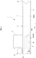
Fig. 1 is a side view of a floating structure as a floating structure in a first embodiment of the present disclosure. -
Fig. 2 is a plan view showing an equipment unit provided in the floating structure in the first embodiment of the present disclosure. -
Fig. 3 is a side sectional view of the equipment unit in the first embodiment of the present disclosure. -
Fig. 4 is a plan view showing an equipment unit provided in the floating structure in a second embodiment of the present disclosure. -
Fig. 5 is a plan view showing an equipment unit provided in the floating structure in a third embodiment of the present disclosure. - Hereinafter, a floating structure as a floating structure according to an embodiment of the present disclosure will be described with reference to
Figs. 1 to 5 . - As shown in
Fig. 1 , afloating structure 1 of this embodiment includes a floatingmain structure 3, asuperstructure 4, acombustion device 8, a plurality ofequipment units 10A, anammonia fuel tank 16, anammonia supply line 17, and apipe system 30. Thefloating structure 1 of the present embodiment will be illustratively described as a ship that can sail using a main engine or the like. A ship type of thefloating structure 1 is not limited to a specific ship type. Examples of the ship type of thefloating structure 1 include a liquefied gas carrier, a ferry, a RORO ship, a car carrier, and a passenger ship. - The floating
main structure 3 includes a pair ofbroadsides bottom 6 forming an outer shell of the floatingmain structure 3. Thebroadsides bottom 6 includes a bottom plate connecting thebroadsides broadsides bottom 6 form the outer shell of the floatingmain structure 3 to have a U-shape in a cross section orthogonal to a bow-stem direction FA. - The floating
main structure 3 further includes anupper deck 7 which is a through deck which is disposed in the uppermost layer. Thesuperstructure 4 is formed on anupper deck 7. An accommodation space and the like are provided inside thesuperstructure 4. In thefloating structure 1 of the present embodiment, for example, a cargo space (not shown) for loading cargo is provided closer to abow 3a side than thesuperstructure 4 in the bow-stern direction FA. - The
combustion device 8 is a device that generates thermal energy by combusting fuel and is provided inside the floatingmain structure 3. Examples of thecombustion device 8 include an internal combustion engine used in a main engine for propulsion of thefloating structure 1, an internal combustion engine used in a power generation facility that supplies power into the ship, and a boiler that generates steam as a working fluid. In thecombustion device 8 of the present embodiment, as fuel, ammonia and another fuel such as light oil different from ammonia can be used by switching. - The plurality of
equipment units 10A are provided in the floatingmain structure 3. In the present embodiment, for example, twoequipment units 10A are disposed (refer toFig. 2 ), but three ormore equipment units 10A may be disposed. In the present embodiment, the plurality ofequipment units 10A are disposed in the same compartment K in the floatingmain structure 3. The compartment K of the present embodiment is exemplified as anengine room 9. The plurality ofequipment units 10A may be disposed in another chamber in the floatingmain structure 3 that is different from theengine room 9. In addition, the compartment in which the plurality ofequipment units 10A are disposed may be provided on theupper deck 7. - The
ammonia fuel tank 16 is a tank that stores liquid ammonia (in other words, liquefied ammonia). Theammonia fuel tank 16 is installed on theupper deck 7 closer to astem 3b side than thesuperstructure 4. Disposition of theammonia fuel tank 16 is an example and is not limited to the disposition on theupper deck 7 closer to thestern 3b side than thesuperstructure 4. Theammonia fuel tank 16 of the present embodiment stores liquefied ammonia as fuel for thecombustion device 8. - The
ammonia supply line 17 connects theammonia fuel tank 16 and theequipment unit 10A and is configured to supply at least the ammonia stored in theammonia fuel tank 16 to theequipment unit 10A. Theammonia supply line 17 is provided with a pump (not shown) that sends the ammonia of theammonia fuel tank 16 to theequipment unit 10A. -
Fig. 2 is a plan view showing an equipment unit provided in the floating structure in the first embodiment of the present disclosure.Fig. 3 is a side sectional view of the equipment unit in the first embodiment of the present disclosure. - As shown in
Figs. 1 to 3 , each of theequipment units 10A includes ammonia fuel-handling equipment 11 and ahousing 20A that accommodates the ammonia fuel-handling equipment 11. - The ammonia fuel-
handling equipment 11 is various types of equipment that handle ammonia fuel. Examples of the ammonia fuel-handling equipment 11 include a pump that pumps ammonia from theammonia fuel tank 16 to thecombustion device 8, a heater that heats the ammonia sent to thecombustion device 8, an electric valve, and the like. The ammonia fuel-handling equipment 11 means all equipment that handles ammonia, and examples thereof include ammonia fuel equipment that handles ammonia and ammonia cargo equipment that handles ammonia as cargo. - In the present embodiment, as the ammonia fuel-handling
equipment 11, afuel supply device 12 that supplies the ammonia fuel to thecombustion device 8 is exemplified. Thefuel supply device 12 includes atemporary storage tank 14 and apump 15. Thetemporary storage tank 14 temporarily stores liquefied ammonia as fuel. Thepump 15 feeds the ammonia fuel stored in thetemporary storage tank 14 to thecombustion device 8. Thefuel supply device 12 includes various valves such as an opening-closing valve and a check valve, and the other equipment (none of which are shown) in addition to thetemporary storage tank 14 and thepump 15 in order to control the interruption of the supply of the ammonia fuel to thecombustion device 8. - The
pipe system 30 connects thefuel supply device 12 of each of theequipment units 10A and thecombustion device 8. Thepipe system 30 supplies the liquefied ammonia of thetemporary storage tank 14 to thecombustion device 8, and returns the surplus ammonia remaining unused as fuel in thecombustion device 8 to thetemporary storage tank 14. In the present embodiment, only a configuration in which the liquefied ammonia of thetemporary storage tank 14 is supplied to thecombustion device 8 as thepipe system 30 is shown, and thepipe system 30 of the present embodiment includes apipe 31 and avalve 32. - The
pipe 31 connects thefuel supply device 12 and thecombustion device 8 to each other, and guides the liquefied ammonia from thefuel supply device 12 to thecombustion device 8. Thevalve 32 is provided in thepipe 31 and is capable of adjusting the flow rate of the liquefied ammonia flowing through thepipe 31. - In the present embodiment, the
fuel supply device 12 of oneequipment unit 10P of the twoequipment units 10A supplies the liquefied ammonia to acombustion device 8A serving as a main engine. In addition, thefuel supply device 12 of theother equipment unit 10Q of the twoequipment units 10A supplies the liquefied ammonia to acombustion device 8B used as an auxiliary machine such as a generator. That is, in the present embodiment, thepipe system 30A connecting thefuel supply device 12 of the oneequipment unit 10P and thecombustion device 8A and thepipe system 30B connecting thefuel supply device 12 of theother equipment unit 10Q and thecombustion device 8B are individually provided. - As shown in
Figs. 2 and3 , thehousing 20A accommodates the ammonia fuel-handlingequipment 11 in each of theequipment units 10A. Thehousing 20A includes abase 21, aframe 22, and acover 25. - The
base 21 is placed on the floor of the compartment K (engine room 9) where theequipment unit 10A is installed. Thebase 21 of the present embodiment is detachably fixed to the floor of the compartment K. Thebase 21 supports the ammonia fuel-handlingequipment 11 from below. Thebase 21 has, for example, a rectangular shape in a plan view when viewed from above. In the present embodiment, theequipment unit 10A is disposed in a posture in which a long side direction D1 of thebase 21 coincides with the bow-stem direction FA. In addition, theequipment unit 10A of the present embodiment is disposed such that a short side direction D2 of thebase 21 coincides with the ship width direction. Thebase 21 is formed of, for example, a steel frame material or the like. The bottom surface or the upper surface of the base 21 may be closed by, for example, an iron plate or the like. The posture of theequipment unit 10A is not limited to the above posture. - The
frame 22 is provided on thebase 21. Theframe 22 includes, for example, fourcolumns 23 that stand upward from four corners of thebase 21, and anupper beam material 24 that connects upper end portions of thecolumns 23 to each other. Theframe 22 is formed to surround the ammonia fuel-handlingequipment 11. Theequipment unit 10A of the present embodiment is accommodated in a so-called container-shapedhousing 20A including thebase 21, theframe 22, and thecover 25. More specifically, theequipment unit 10A has an outer shape equivalent to that of the ISO standard marine container, with thebase 21, theframe 22, and thecover 25. - The
cover 25 is attached to theframe 22. Thecover 25 is disposed to cover the upper portion of theframe 22 and the four side surfaces of theframe 22 when viewed from above. Thecover 25 has a plate shape, and an outer peripheral portion thereof is fixed to theframe 22. Thecover 25 may be formed of, for example, a resin-based material such as polycarbonate or acryl. In addition, thecover 25 may be formed of a light-transmitting material such that theentire cover 25 or at least a part of thecover 25 allows the internal state of thehousing 20A to be visually recognized from the outside. Thecover 25 may be formed of a material that does not contain copper or the like that reacts with ammonia by being in contact with ammonia, and is not limited to being formed of the above-described resin-based material. - As shown in
Fig. 3 , theequipment unit 10A of the present embodiment further includes awater sprinkling device 50 and aventilation device 53. - The
water sprinkling device 50 sprinkles water in thehousing 20A in a case where the leakage of the ammonia fuel occurs in thehousing 20A. Thewater sprinkling device 50 includes awater supply pipe 51 and awater sprinkling nozzle 52. Thewater supply pipe 51 supplies water from the outside of thehousing 20A. Thewater sprinkling nozzle 52 sprinkles the water supplied through thewater supply pipe 51 into thehousing 20A. A plurality of thewater sprinkling nozzles 52 may be provided in the upper portion in thehousing 20A. - The
ventilation device 53 discharges the vaporized ammonia to the outside of thehousing 20A in a case where the leakage of the ammonia fuel occurs in thehousing 20A. Theventilation device 53 includes aduct 54 and afan 55. One end of theduct 54 is connected to a through-hole (not shown) formed in thecover 25 of thehousing 20A. The other end of theduct 54 is connected to an exhaust duct (not shown) or a detoxification facility (not shown) provided in the floatingmain structure 3. Thefan 55 discharges the ammonia (gas) that has occurred inside thehousing 20A to the outside through theduct 54. Theventilation device 53 may be either a positive pressure type or a negative pressure type but is preferably a negative pressure type from the viewpoint of suppressing leakage of ammonia to the surroundings. - In addition, the pressure of the atmosphere in the
housing 20A may be reduced due to the water sprinkling in thewater sprinkling device 50, the exhaust of the ammonia (gas) in theventilation device 53, or the like. For this reason, theequipment unit 10A may be provided with a relief valve (not shown) that is opened in a case where the pressure of the atmosphere in thehousing 20A is reduced by a predetermined value or more, in thecover 25. - In addition, the
equipment unit 10A may be provided with the water recovery unit (not shown) that recovers the water sprinkled by thewater sprinkling device 50. As shown inFig. 3 , in the embodiment of the present disclosure, the water recovery unit (not shown) discharges, for example, the water sprinkled by thewater sprinkling device 50 and stored in the bottom portion in thehousing 20A to the outside of thehousing 20A. Here, the water recovery unit (not shown) discharges the recovered water to the outside of the floatingmain structure 3. - In addition, the
equipment unit 10A may be provided with the camera (not shown) that captures a state inside thehousing 20A in a case where the leakage of the ammonia fuel occurs inside thehousing 20A. The image (video) captured by the camera is displayed on a monitor or the like of amonitoring device 59 that monitors the operating state of theequipment unit 10A. The person in charge of monitoring the operating state of theequipment unit 10A can remotely confirm the state inside thehousing 20A by viewing the monitor or the like. - Further, the
equipment unit 10A may include asensor 58 that detects the presence or absence of leakage of the ammonia fuel in thehousing 20A. In a case where the occurrence of the leakage of the ammonia fuel in thehousing 20A is detected by thesensor 58, themonitoring device 59 may externally notify that the leakage has occurred via a predetermined warning sound, a message, warning lamp lighting, or the like. Furthermore, in response to this, the person in charge of monitoring the operating state of theequipment unit 10A may perform an operation of operating thevalve 32, thewater sprinkling device 50, theventilation device 53, the camera (not shown), or the like with themonitoring device 59. In addition, in themonitoring device 59, when thesensor 58 detects the occurrence of the leakage of the ammonia fuel in thehousing 20A, thevalve 32, thewater sprinkling device 50, theventilation device 53, the camera (not shown), or the like may be automatically operated based on a computer program set in advance. - In the floating
structure 1 of the above embodiment, the plurality ofequipment units 10A including the ammonia fuel-handlingequipment 11 are provided in the floatingmain structure 3. Each of theequipment units 10A includes thecover 25 that covers the ammonia fuel-handlingequipment 11. Accordingly, even when the ammonia fuel leaks from the ammonia fuel-handlingequipment 11, the leaked ammonia fuel is retained inside thecover 25. Accordingly, the diffusion of the ammonia fuel to the outside of thecover 25 is suppressed. Thecover 25 may be provided for each of the ammonia fuel-handlingequipment 11, and the diffusion of the ammonia fuel can be suppressed by a simple configuration. Therefore, it is possible to suppress diffusion of ammonia into the floatingmain structure 3 while suppressing an increase in complexity of a structure and an increase in cost. - In addition, in a case where the leakage of the ammonia fuel occurs in only some of the plurality of
equipment units 10A, the operation of the ammonia fuel-handlingequipment 11 can be continued inother equipment units 10A. In addition, in theequipment unit 10A in which the ammonia fuel leaks, in a case where the water sprinkling is performed by thewater sprinkling device 50, the sprinkled water is suppressed from spreading to the outside of thehousing 20A of theequipment unit 10A. As a result, the post-treatment after the water sprinkling can also be performed in a short time. - In the above embodiment, the
equipment unit 10A further includes thewater sprinkling device 50. - Accordingly, in a case where the ammonia fuel leaks from the ammonia fuel-handling
equipment 11 into thecover 25, the ammonia is absorbed by the water by thewater sprinkling device 50 sprinkling the water into the space in thecover 25. Therefore, it is possible to effectively suppress the diffusion of the ammonia into the floatingmain structure 3. In addition, since the volume inside thehousing 20A is small as compared with a case where the water sprinkling is performed in the entire compartment K, the amount of water sprinkling can be reduced, and the ammonia can be quickly absorbed. - In addition, since the
equipment unit 10A includes theventilation device 53, in a case where the ammonia fuel leaks from the ammonia fuel-handlingequipment 11 into thecover 25, the ammonia in thecover 25 can be discharged to the outside by theventilation device 53. In this case, as compared with a case where ventilation is performed in the entire compartment K, the volume inside thehousing 20A is small, and ventilation can be quickly performed. In addition, since theventilation device 53 is provided in each of theequipment units 10A, the capacity of thefan 55 can be reduced, and thus the cost can be reduced. - In the above embodiment, the plurality of
equipment units 10A are disposed in the same compartment K in the floatingmain structure 3. Accordingly, in a case where the plurality ofequipment units 10A are disposed in the same compartment K in the floatingmain structure 3, even when the leakage of the ammonia fuel occurs in someequipment units 10A of the plurality ofequipment units 10A, the leakage of the ammonia fuel to the outside of thecover 25 of theequipment units 10A in which the leakage of the ammonia fuel has occurred is suppressed. Therefore, the influence onother equipment units 10A can be suppressed, and the operation of the ammonia fuel-handlingequipment 11 inother equipment units 10A can also be continued. - In the above-described embodiment, at least a part of the
cover 25 is formed to be capable of transmitting light from the outside to the inside of thecover 25. Therefore, the operation of the ammonia fuel equipment, the presence or absence of leakage of the ammonia fuel, and the like inside thecover 25 can be visually confirmed from the outside of thecover 25. - The floating
structure 1 of the above embodiment includes thebase 21 and theframe 22 formed to surround the ammonia fuel-handlingequipment 11, and thecover 25 is attached to theframe 22. Therefore, theequipment unit 10A can be transported and installed in the floatingmain structure 3 in the same manner as a container or the like. When thehousing 20A has a size that can be transported by a vehicle such as a trailer or a truck, thehousing 20A can be easily transported to the outside of the floatingstructure 1 when thehousing 20A is installed. Further, by making thehousing 20A have the same strength as or higher strength than that of a marine container such as a so-called ISO container, so-called stacking in which a plurality of thehousings 20A are stacked and disposed up and down can also be performed. - In the above-described embodiment, since the ammonia fuel-handling
equipment 11 includes thefuel supply device 12 capable of supplying the ammonia fuel, in a case where the ammonia fuel leaks in thefuel supply device 12 provided in the floatingmain structure 3, it is possible to suppress the diffusion of the ammonia into the floatingmain structure 3. - Next, a second embodiment of the floating structure according to the present disclosure will be described. In the second embodiment that is described below, since only the configuration of the equipment unit is different from that in the first embodiment, the same portions as those in the first embodiment are denoted by the same reference numerals, and overlapping description is omitted.
-
Fig. 4 is a plan view showing an equipment unit provided in the floating structure in a second embodiment of the present disclosure. - As shown in
Fig. 4 , anequipment unit 10B of the floatingstructure 1 of the second embodiment includes the ammonia fuel-handlingequipment 11 and ahousing 20B. - An
opening 26 that allows the inside and the outside of thecover 25 to communicate with each other is formed in thecover 25 of thehousing 20B. - In addition, the compartment K (engine room 9) in which a plurality of the
housings 20B are disposed is provided with an in-compartmentwater sprinkling device 60. The in-compartmentwater sprinkling device 60 sprinkles water in the compartment K in a case where the leakage of the ammonia fuel occurs in at least one of the plurality ofhousings 20B. The in-compartmentwater sprinkling device 60 includes awater supply pipe 61 and awater sprinkling nozzle 62. Thewater supply pipe 61 supplies water from the outside of the compartment K. Thewater sprinkling nozzle 62 sprinkles the water supplied through thewater supply pipe 61 into the compartment K. A plurality of thewater sprinkling nozzles 62 may be provided in the upper portion in thehousing 20B in the compartment K. - According to the second embodiment, the
cover 25 includes theopening 26, and the in-compartmentwater sprinkling device 60 is provided in the compartment K in which theequipment unit 10B is disposed. Therefore, in a case where the ammonia fuel leaks from the ammonia fuel-handlingequipment 11, the ammonia fuel is discharged to the space outside thecover 25 through theopening 26. The ammonia is absorbed by the water sprinkling via the in-compartmentwater sprinkling device 60 with respect to the discharged ammonia fuel. - In addition, each
equipment unit 10B includes thecover 25. Therefore, in a case where water is sprinkled from the in-compartmentwater sprinkling device 60, it is possible to suppress the ammonia fuel-handlingequipment 11 of eachequipment unit 10B from being wet with water. - In the second embodiment, a case where the
water sprinkling device 50 is provided in thehousing 20B has been described. However, thewater sprinkling device 50 provided in thehousing 20B may be omitted. In addition, a case where thehousing 20B is provided with theventilation device 53 has been described. However, theventilation device 53 may be omitted. In a case where thehousing 20B is not provided with theventilation device 53, the same configuration as theventilation device 53 may be provided in the compartment K. - Next, a third embodiment of the floating structure according to the present disclosure will be described. In the third embodiment that is described below, since only the configuration including the connection unit is different from that in the second embodiment, the same portions as those in the first embodiment are denoted by the same reference numerals, and overlapping description is omitted.
-
Fig. 5 is a plan view showing an equipment unit provided in the floating structure in a third embodiment of the present disclosure. - As shown in
Fig. 5 , the floatingstructure 1 of the third embodiment includes aconnection unit 70 disposed between the plurality ofequipment units 10A. - The plurality of
equipment units 10A are disposed on the floor surface of the compartment K (engine room 9) at intervals in the horizontal direction. Here, inFig. 5 , a case where the plurality ofequipment units 10A are disposed at intervals in the short side direction D2 of theequipment unit 10A having a rectangular shape in a plan view is exemplified. However, the plurality ofequipment units 10A may be disposed at intervals in the long side direction D1 of theequipment unit 10A having a rectangular shape in a plan view. In addition, theconnection unit 70 can be stacked and disposed on theequipment unit 10A up and down, which is so-called stacking. - The
connection unit 70 includes aconnection pipe 71. Theconnection pipe 71 connects the ammonia fuel-handlingequipment 11 of theadjacent equipment units 10A with theconnection unit 70 interposed therebetween. Theconnection unit 70 includes ahousing 80 that covers theconnection pipe 71. Thehousing 80 includes thebase 21 and theframe 22, which are the same as those of theequipment unit 10A, and apipe cover 75. Thepipe cover 75 is attached to theframe 22 and is disposed to cover the upper portion and the side of theframe 22 between the plurality ofequipment units 10A. - According to the third embodiment, the
connection pipe 71 and thepipe cover 75 covering theconnection pipe 71 are disposed between the plurality ofequipment units 10A. Therefore, even in a case where the ammonia fuel leaks from theconnection pipe 71 provided to cross the plurality ofequipment units 10A, the diffusion of the ammonia into the floatingmain structure 3 can be suppressed. - In the third embodiment, the
connection unit 70 including theconnection pipe 71 and thepipe cover 75 is disposed between the plurality ofequipment units 10A shown in the first embodiment. However, theequipment unit 10B shown in the second embodiment may be disposed instead of theequipment unit 10A. - The embodiments of the present disclosure have been described in detail with reference to the drawings hereinbefore. However, the specific configuration is not limited to the embodiments, and includes design changes and the like within a scope not departing from the gist of the present disclosure.
- For example, in the above embodiment, a case where the floating
structure 1 is a ship that can sail using a main engine or the like has been described. However, the floatingstructure 1 is not limited to a ship as long as it is a floating structure. - Further, in the above-described embodiment, the
fuel supply device 12 of the oneequipment unit 10P supplies the ammonia fuel to thecombustion device 8A serving as the main engine, and thefuel supply device 12 of theother equipment unit 10Q supplies the ammonia fuel to thecombustion device 8B used as the auxiliary machine. However, the present disclosure is not limited thereto. The ammonia fuel may be supplied from thefuel supply devices 12 of the plurality ofequipment units equipment 11. In addition, the ammonia fuel may be distributed and supplied from thefuel supply device 12 of the twoequipment units equipment 11. - In addition, in each of the above-described embodiments, the
respective equipment units fuel supply device 12 as the ammonia fuel-handlingequipment 11. However, the present disclosure is not limited to this configuration. For example, in addition to thefuel supply device 12, thecombustion device 8 may be disposed in thehousings respective equipment units - Further, in each of the embodiments, a case has been described in which the
respective equipment units equipment units - For example, the floating
structure 1 described in each of the embodiments is understood as follows. -
- (1) A floating
structure 1 according to a first aspect includes a floatingmain structure 3, and a plurality ofequipment units main structure 3, in which each of the plurality ofequipment units equipment 11, and acover 25 that covers the ammonia fuel-handlingequipment 11 such that each of the ammonia fuel-handlingequipment 11 is disposed on an inner side. - Examples of the ammonia fuel-handling
equipment 11 include thefuel supply device 12 and thecombustion device 8. - In the floating
structure 1, the plurality ofequipment units equipment 11 are provided in the floatingmain structure 3. Each of theequipment units cover 25 that covers the ammonia fuel-handlingequipment 11. Accordingly, even when the ammonia fuel leaks from the ammonia fuel-handlingequipment 11, the leaked ammonia fuel is retained inside thecover 25. The diffusion of the ammonia fuel to the outside of thecover 25 is suppressed. Thecover 25 may be provided for each of the ammonia fuel-handlingequipment 11, and the diffusion of the ammonia fuel can be suppressed by a simple configuration. Therefore, it is possible to suppress diffusion of ammonia into the floatingmain structure 3 in a case where the ammonia fuel leaks while suppressing an increase in complexity of a structure and an increase in cost. - (2) A floating
structure 1 according to a second aspect is the floatingstructure 1 of (1), in which theequipment unit water sprinkling device 50 capable of sprinkling water into a space in thecover 25. - Accordingly, in a case where the ammonia fuel leaks from the ammonia fuel-handling
equipment 11 into thecover 25, the ammonia is absorbed by the water by thewater sprinkling device 50 sprinkling the water into the space in thecover 25. Therefore, it is possible to effectively suppress the diffusion of the ammonia into the floatingmain structure 3. - (3) A floating
structure 1 according to a third aspect is the floatingstructure 1 of (1) or (2), in which the plurality ofequipment units main structure 3. - Accordingly, in a case where the plurality of
equipment units main structure 3, even when the leakage of the ammonia fuel occurs in someequipment units equipment units cover 25 of theequipment units other equipment units equipment 11 inother equipment units - (4) A floating
structure 1 according to a fourth aspect is the floatingstructure 1 of (3), in which thecover 25 has anopening 26 through which an inside and an outside of thecover 25 communicate with each other, and an in-compartmentwater sprinkling device 60 capable of sprinkling water in the compartment K in which theequipment unit 10B is disposed is provided in the compartment K. - Therefore, in a case where the ammonia fuel leaks from the ammonia fuel-handling
equipment 11, the ammonia fuel is discharged to the space outside thecover 25 through theopening 26. The ammonia can be absorbed in water by the water sprinkling via the in-compartmentwater sprinkling device 60 with respect to the discharged ammonia fuel. - (5) A floating
structure 1 according to a fifth aspect is the floatingstructure 1 of any one of (1) to (4), in which at least a part of thecover 25 is formed to be capable of transmitting light from an outside to an inside of thecover 25. - Accordingly, the presence or absence of the leakage of the ammonia fuel, and the like can be visually confirmed from the outside of the
cover 25. - (6) A floating
structure 1 according to a sixth aspect is the floatingstructure 1 of any one of (1) to (5), the floatingstructure 1 includes a base 21 that supports the ammonia fuel-handlingequipment 11, and aframe 22 that is provided on thebase 21 and is formed to surround the ammonia fuel-handlingequipment 11, in which thecover 25 is attached to theframe 22. - Therefore, the
equipment units main structure 3. - (7) A floating
structure 1 according to a seventh aspect is the floatingstructure 1 of any one of (1) to (6), in which the ammonia fuel-handlingequipment 11 includes afuel supply device 12 capable of supplying ammonia fuel. - Therefore, it is possible to suppress diffusion of ammonia into the floating
main structure 3 in a case where the ammonia fuel leaks, in thefuel supply device 12 provided in the floatingmain structure 3. - (8) A floating
structure 1 according to an eighth aspect is the floatingstructure 1 of any one of (1) to (7), in which the plurality ofequipment units connection pipe 71 that connects the ammonia fuel-handlingequipment 11 of the plurality ofequipment units pipe cover 75 that covers theconnection pipe 71 are disposed between the plurality ofequipment units - Accordingly, the
connection pipe 71 for connecting the ammonia fuel-handlingequipment 11 of theequipment units pipe cover 75. Therefore, in a case where the ammonia fuel leaks from theconnection pipe 71, the diffusion of the ammonia into the floatingmain structure 3 can be suppressed. - According to the floating structure of the present disclosure, it is possible to suppress diffusion of ammonia into a floating main structure while suppressing an increase in complexity of a structure and an increase in cost.
-
- 1: floating structure
- 3: floating main structure
- 3a: bow
- 4: superstructure
- 5A, 5B: broadside
- 6: bottom
- 7: upper deck
- 8, 8A, 8B: combustion device
- 9: engine room
- 10A, 10B, 10P, 10Q: equipment unit
- 11: ammonia fuel-handling equipment
- 12: fuel supply device
- 14: temporary storage tank
- 15: pump
- 16: ammonia fuel tank
- 17: ammonia supply line
- 20A, 20B: housing
- 21: base
- 22: frame
- 23: column
- 24: upper beam material
- 25: cover
- 25h: through-hole
- 26: opening
- 30, 30A, 30B: pipe system
- 31: pipe
- 32: valve
- 50: water sprinkling device
- 51: water supply pipe
- 52: water sprinkling nozzle
- 53: ventilation device
- 54: duct
- 55: fan
- 58: sensor
- 59: monitoring device
- 60: in-compartment water sprinkling device
- 61: water supply pipe
- 62: water sprinkling nozzle
- 70: connection unit
- 71: connection pipe
- 75: pipe cover
- 80: housing
- K: compartment
Claims (8)
- A floating structure comprising:a floating main structure; anda plurality of equipment units provided in the floating main structure,wherein each of the plurality of equipment units includesammonia fuel-handling equipment, anda cover that covers the ammonia fuel-handling equipment such that each of the ammonia fuel-handling equipment is disposed on an inner side.
- The floating structure according to Claim 1,
wherein the equipment unit further includes a water sprinkling device capable of sprinkling water into a space in the cover. - The floating structure according to Claim 1 or 2,
wherein the plurality of equipment units are disposed in the same compartment in the floating main structure. - The floating structure according to Claim 3,wherein the cover has an opening through which an inside and an outside of the cover communicate with each other, andan in-compartment water sprinkling device capable of sprinkling water in the compartment in which the equipment unit is disposed is provided in the compartment.
- The floating structure according to Claim 1 or 2,
wherein at least a part of the cover is formed to be capable of transmitting light from an outside to an inside of the cover. - The floating structure according to Claim 1 or 2, further comprising:a base that supports the ammonia fuel-handling equipment; anda frame that is provided on the base and is formed to surround the ammonia fuel-handling equipment,wherein the cover is attached to the frame.
- The floating structure according to Claim 1 or 2,
wherein the ammonia fuel-handling equipment includes a fuel supply device capable of supplying ammonia fuel. - The floating structure according to Claim 1 or 2,wherein the plurality of equipment units are disposed at intervals, anda connection pipe that connects the ammonia fuel-handling equipment of the plurality of equipment units to each other and a pipe cover that covers the connection pipe are disposed between the plurality of equipment units.
Applications Claiming Priority (2)
| Application Number | Priority Date | Filing Date | Title |
|---|---|---|---|
| JP2022027397A JP7840172B2 (en) | 2022-02-25 | 2022-02-25 | Floating body |
| PCT/JP2022/041150 WO2023162353A1 (en) | 2022-02-25 | 2022-11-04 | Floating structure |
Publications (2)
| Publication Number | Publication Date |
|---|---|
| EP4464594A1 true EP4464594A1 (en) | 2024-11-20 |
| EP4464594A4 EP4464594A4 (en) | 2025-05-21 |
Family
ID=87765410
Family Applications (1)
| Application Number | Title | Priority Date | Filing Date |
|---|---|---|---|
| EP22928871.7A Pending EP4464594A4 (en) | 2022-02-25 | 2022-11-04 | FLOATING STRUCTURE |
Country Status (5)
| Country | Link |
|---|---|
| EP (1) | EP4464594A4 (en) |
| JP (1) | JP7840172B2 (en) |
| KR (1) | KR20240134369A (en) |
| CN (1) | CN118660845A (en) |
| WO (1) | WO2023162353A1 (en) |
Families Citing this family (3)
| Publication number | Priority date | Publication date | Assignee | Title |
|---|---|---|---|---|
| WO2025249886A1 (en) * | 2024-05-30 | 2025-12-04 | 에이치디한국조선해양 주식회사 | Method and apparatus for detecting leakage of ammonia |
| JP7781983B1 (en) | 2024-07-31 | 2025-12-08 | 株式会社新来島どっく | Structure to prevent the diffusion of ammonia leaks from ammonia-fueled ships and to prevent intrusion into work areas |
| JP7849456B1 (en) * | 2024-12-25 | 2026-04-21 | 株式会社新来島どっく | Ammonia diffusion prevention device for ammonia-fueled ships |
Family Cites Families (12)
| Publication number | Priority date | Publication date | Assignee | Title |
|---|---|---|---|---|
| JP3078789B2 (en) | 1998-11-16 | 2000-08-21 | 株式会社前川製作所 | Marine refrigeration / air conditioning system using ammonia refrigerant |
| JP3066828B1 (en) * | 1999-02-17 | 2000-07-17 | 株式会社前川製作所 | Ammonia refrigeration system leakage ammonia elimination device |
| JP3078789U (en) | 2000-11-20 | 2001-07-19 | ビーエフ工業株式会社 | Pressurized filtration separator |
| JP4002507B2 (en) * | 2002-12-20 | 2007-11-07 | 株式会社前川製作所 | NH3 heat pump |
| JP5839791B2 (en) | 2010-10-14 | 2016-01-06 | 三菱重工業株式会社 | Marine SCR reducing agent supply system |
| KR102745935B1 (en) * | 2019-12-04 | 2024-12-20 | 한화엔진 주식회사 | Ammonia supply system |
| JP2022027397A (en) | 2020-07-29 | 2022-02-10 | 株式会社ジェイテクト | Method of measuring preload on bearing device and method of manufacturing bearing device |
| JP6983964B1 (en) * | 2020-08-25 | 2021-12-17 | 三菱造船株式会社 | Ship |
| KR102204875B1 (en) * | 2020-08-31 | 2021-01-19 | (주)앤써 | A system for emergency discharging lpg and the ship or offshore structure including the same |
| KR102562098B1 (en) * | 2021-07-30 | 2023-08-01 | 삼성중공업 주식회사 | Ammonia treatment system of ship |
| CN113623089B (en) * | 2021-08-11 | 2023-01-24 | 中国船舶重工集团柴油机有限公司 | A kind of marine ammonia supply system and ship |
| KR102608685B1 (en) * | 2021-09-17 | 2023-12-01 | 한화오션 주식회사 | Ammonia Leakage Treatment System In Engine Room For Ammonia Fueled Ship |
-
2022
- 2022-02-25 JP JP2022027397A patent/JP7840172B2/en active Active
- 2022-11-04 KR KR1020247027013A patent/KR20240134369A/en active Pending
- 2022-11-04 EP EP22928871.7A patent/EP4464594A4/en active Pending
- 2022-11-04 CN CN202280091914.6A patent/CN118660845A/en active Pending
- 2022-11-04 WO PCT/JP2022/041150 patent/WO2023162353A1/en not_active Ceased
Also Published As
| Publication number | Publication date |
|---|---|
| CN118660845A (en) | 2024-09-17 |
| KR20240134369A (en) | 2024-09-09 |
| JP7840172B2 (en) | 2026-04-03 |
| WO2023162353A1 (en) | 2023-08-31 |
| EP4464594A4 (en) | 2025-05-21 |
| JP2023123920A (en) | 2023-09-06 |
Similar Documents
| Publication | Publication Date | Title |
|---|---|---|
| KR102077894B1 (en) | Gas Fuelled Container Carrier | |
| KR20240134369A (en) | Body | |
| KR101764015B1 (en) | Gas Fuelled Container Carrier | |
| CN107000814B (en) | Floating body structure with liquefied gas storage device | |
| CN110099842B (en) | Container transport ship propelled by gas fuel | |
| JP6388150B2 (en) | LNG ship | |
| JP7657100B2 (en) | Fuel Cell Ship | |
| JP5839791B2 (en) | Marine SCR reducing agent supply system | |
| JP7813128B2 (en) | Floating structures | |
| JP7813127B2 (en) | Floating structures | |
| KR20240112857A (en) | floating structure | |
| JP7698483B2 (en) | Cargo ship | |
| KR20250019078A (en) | Body | |
| JP2025164841A (en) | Fuel cell ships and power generation systems | |
| KR102806914B1 (en) | Fuel treatment system and ship having the same | |
| WO2023204082A1 (en) | Ship | |
| JP2023087285A (en) | floating structure | |
| KR102743803B1 (en) | Ammonia treatment system and ship including the same | |
| CN117203121B (en) | Cargo transport ship | |
| KR20250144240A (en) | ship | |
| KR20240112858A (en) | floating structure | |
| KR20260051121A (en) | A fuel cell propulsion ship | |
| KR20260029249A (en) | Ship |
Legal Events
| Date | Code | Title | Description |
|---|---|---|---|
| STAA | Information on the status of an ep patent application or granted ep patent |
Free format text: STATUS: THE INTERNATIONAL PUBLICATION HAS BEEN MADE |
|
| PUAI | Public reference made under article 153(3) epc to a published international application that has entered the european phase |
Free format text: ORIGINAL CODE: 0009012 |
|
| STAA | Information on the status of an ep patent application or granted ep patent |
Free format text: STATUS: REQUEST FOR EXAMINATION WAS MADE |
|
| 17P | Request for examination filed |
Effective date: 20240813 |
|
| AK | Designated contracting states |
Kind code of ref document: A1 Designated state(s): AL AT BE BG CH CY CZ DE DK EE ES FI FR GB GR HR HU IE IS IT LI LT LU LV MC ME MK MT NL NO PL PT RO RS SE SI SK SM TR |
|
| A4 | Supplementary search report drawn up and despatched |
Effective date: 20250422 |
|
| RIC1 | Information provided on ipc code assigned before grant |
Ipc: B63B 43/00 20060101ALI20250414BHEP Ipc: B63B 17/00 20060101ALI20250414BHEP Ipc: B63J 2/06 20060101ALI20250414BHEP Ipc: B63H 21/38 20060101AFI20250414BHEP |
|
| DAV | Request for validation of the european patent (deleted) | ||
| DAX | Request for extension of the european patent (deleted) |