EP4464547A1 - Temperieranordnung und verfahren zur herstellung einer temperieranordnung - Google Patents
Temperieranordnung und verfahren zur herstellung einer temperieranordnung Download PDFInfo
- Publication number
- EP4464547A1 EP4464547A1 EP23173842.8A EP23173842A EP4464547A1 EP 4464547 A1 EP4464547 A1 EP 4464547A1 EP 23173842 A EP23173842 A EP 23173842A EP 4464547 A1 EP4464547 A1 EP 4464547A1
- Authority
- EP
- European Patent Office
- Prior art keywords
- temperature control
- channel
- fluid
- cap
- tempering
- Prior art date
- Legal status (The legal status is an assumption and is not a legal conclusion. Google has not performed a legal analysis and makes no representation as to the accuracy of the status listed.)
- Granted
Links
Images

Classifications
-
- H—ELECTRICITY
- H01—ELECTRIC ELEMENTS
- H01M—PROCESSES OR MEANS, e.g. BATTERIES, FOR THE DIRECT CONVERSION OF CHEMICAL ENERGY INTO ELECTRICAL ENERGY
- H01M10/00—Secondary cells; Manufacture thereof
- H01M10/60—Heating or cooling; Temperature control
- H01M10/61—Types of temperature control
- H01M10/613—Cooling or keeping cold
-
- H—ELECTRICITY
- H01—ELECTRIC ELEMENTS
- H01M—PROCESSES OR MEANS, e.g. BATTERIES, FOR THE DIRECT CONVERSION OF CHEMICAL ENERGY INTO ELECTRICAL ENERGY
- H01M10/00—Secondary cells; Manufacture thereof
- H01M10/60—Heating or cooling; Temperature control
- H01M10/65—Means for temperature control structurally associated with the cells
- H01M10/655—Solid structures for heat exchange or heat conduction
- H01M10/6556—Solid parts with flow channel passages or pipes for heat exchange
-
- F—MECHANICAL ENGINEERING; LIGHTING; HEATING; WEAPONS; BLASTING
- F28—HEAT EXCHANGE IN GENERAL
- F28F—DETAILS OF HEAT-EXCHANGE AND HEAT-TRANSFER APPARATUS, OF GENERAL APPLICATION
- F28F3/00—Plate-like or laminated elements; Assemblies of plate-like or laminated elements
- F28F3/12—Elements constructed in the shape of a hollow panel, e.g. with channels
-
- H—ELECTRICITY
- H01—ELECTRIC ELEMENTS
- H01M—PROCESSES OR MEANS, e.g. BATTERIES, FOR THE DIRECT CONVERSION OF CHEMICAL ENERGY INTO ELECTRICAL ENERGY
- H01M10/00—Secondary cells; Manufacture thereof
- H01M10/60—Heating or cooling; Temperature control
- H01M10/61—Types of temperature control
- H01M10/617—Types of temperature control for achieving uniformity or desired distribution of temperature
-
- H—ELECTRICITY
- H01—ELECTRIC ELEMENTS
- H01M—PROCESSES OR MEANS, e.g. BATTERIES, FOR THE DIRECT CONVERSION OF CHEMICAL ENERGY INTO ELECTRICAL ENERGY
- H01M10/00—Secondary cells; Manufacture thereof
- H01M10/60—Heating or cooling; Temperature control
- H01M10/62—Heating or cooling; Temperature control specially adapted for specific applications
- H01M10/625—Vehicles
-
- H—ELECTRICITY
- H01—ELECTRIC ELEMENTS
- H01M—PROCESSES OR MEANS, e.g. BATTERIES, FOR THE DIRECT CONVERSION OF CHEMICAL ENERGY INTO ELECTRICAL ENERGY
- H01M10/00—Secondary cells; Manufacture thereof
- H01M10/60—Heating or cooling; Temperature control
- H01M10/63—Control systems
-
- H—ELECTRICITY
- H01—ELECTRIC ELEMENTS
- H01M—PROCESSES OR MEANS, e.g. BATTERIES, FOR THE DIRECT CONVERSION OF CHEMICAL ENERGY INTO ELECTRICAL ENERGY
- H01M10/00—Secondary cells; Manufacture thereof
- H01M10/60—Heating or cooling; Temperature control
- H01M10/65—Means for temperature control structurally associated with the cells
- H01M10/656—Means for temperature control structurally associated with the cells characterised by the type of heat-exchange fluid
-
- H—ELECTRICITY
- H01—ELECTRIC ELEMENTS
- H01M—PROCESSES OR MEANS, e.g. BATTERIES, FOR THE DIRECT CONVERSION OF CHEMICAL ENERGY INTO ELECTRICAL ENERGY
- H01M10/00—Secondary cells; Manufacture thereof
- H01M10/60—Heating or cooling; Temperature control
- H01M10/65—Means for temperature control structurally associated with the cells
- H01M10/656—Means for temperature control structurally associated with the cells characterised by the type of heat-exchange fluid
- H01M10/6567—Liquids
- H01M10/6568—Liquids characterised by flow circuits, e.g. loops, located externally to the cells or cell casings
-
- H—ELECTRICITY
- H01—ELECTRIC ELEMENTS
- H01M—PROCESSES OR MEANS, e.g. BATTERIES, FOR THE DIRECT CONVERSION OF CHEMICAL ENERGY INTO ELECTRICAL ENERGY
- H01M50/00—Constructional details or processes of manufacture of the non-active parts of electrochemical cells other than fuel cells, e.g. hybrid cells
- H01M50/20—Mountings; Secondary casings or frames; Racks, modules or packs; Suspension devices; Shock absorbers; Transport or carrying devices; Holders
- H01M50/204—Racks, modules or packs for multiple batteries or multiple cells
-
- H—ELECTRICITY
- H01—ELECTRIC ELEMENTS
- H01M—PROCESSES OR MEANS, e.g. BATTERIES, FOR THE DIRECT CONVERSION OF CHEMICAL ENERGY INTO ELECTRICAL ENERGY
- H01M50/00—Constructional details or processes of manufacture of the non-active parts of electrochemical cells other than fuel cells, e.g. hybrid cells
- H01M50/20—Mountings; Secondary casings or frames; Racks, modules or packs; Suspension devices; Shock absorbers; Transport or carrying devices; Holders
- H01M50/244—Secondary casings; Racks; Suspension devices; Carrying devices; Holders characterised by their mounting method
-
- H—ELECTRICITY
- H01—ELECTRIC ELEMENTS
- H01M—PROCESSES OR MEANS, e.g. BATTERIES, FOR THE DIRECT CONVERSION OF CHEMICAL ENERGY INTO ELECTRICAL ENERGY
- H01M50/00—Constructional details or processes of manufacture of the non-active parts of electrochemical cells other than fuel cells, e.g. hybrid cells
- H01M50/20—Mountings; Secondary casings or frames; Racks, modules or packs; Suspension devices; Shock absorbers; Transport or carrying devices; Holders
- H01M50/249—Mountings; Secondary casings or frames; Racks, modules or packs; Suspension devices; Shock absorbers; Transport or carrying devices; Holders specially adapted for aircraft or vehicles, e.g. cars or trains
-
- H—ELECTRICITY
- H01—ELECTRIC ELEMENTS
- H01M—PROCESSES OR MEANS, e.g. BATTERIES, FOR THE DIRECT CONVERSION OF CHEMICAL ENERGY INTO ELECTRICAL ENERGY
- H01M50/00—Constructional details or processes of manufacture of the non-active parts of electrochemical cells other than fuel cells, e.g. hybrid cells
- H01M50/20—Mountings; Secondary casings or frames; Racks, modules or packs; Suspension devices; Shock absorbers; Transport or carrying devices; Holders
- H01M50/271—Lids or covers for the racks or secondary casings
-
- B—PERFORMING OPERATIONS; TRANSPORTING
- B60—VEHICLES IN GENERAL
- B60L—PROPULSION OF ELECTRICALLY-PROPELLED VEHICLES; SUPPLYING ELECTRIC POWER FOR AUXILIARY EQUIPMENT OF ELECTRICALLY-PROPELLED VEHICLES; ELECTRODYNAMIC BRAKE SYSTEMS FOR VEHICLES IN GENERAL; MAGNETIC SUSPENSION OR LEVITATION FOR VEHICLES; MONITORING OPERATING VARIABLES OF ELECTRICALLY-PROPELLED VEHICLES; ELECTRIC SAFETY DEVICES FOR ELECTRICALLY-PROPELLED VEHICLES
- B60L50/00—Electric propulsion with power supplied within the vehicle
- B60L50/50—Electric propulsion with power supplied within the vehicle using propulsion power supplied by batteries or fuel cells
- B60L50/60—Electric propulsion with power supplied within the vehicle using propulsion power supplied by batteries or fuel cells using power supplied by batteries
- B60L50/64—Constructional details of batteries specially adapted for electric vehicles
-
- B—PERFORMING OPERATIONS; TRANSPORTING
- B60—VEHICLES IN GENERAL
- B60L—PROPULSION OF ELECTRICALLY-PROPELLED VEHICLES; SUPPLYING ELECTRIC POWER FOR AUXILIARY EQUIPMENT OF ELECTRICALLY-PROPELLED VEHICLES; ELECTRODYNAMIC BRAKE SYSTEMS FOR VEHICLES IN GENERAL; MAGNETIC SUSPENSION OR LEVITATION FOR VEHICLES; MONITORING OPERATING VARIABLES OF ELECTRICALLY-PROPELLED VEHICLES; ELECTRIC SAFETY DEVICES FOR ELECTRICALLY-PROPELLED VEHICLES
- B60L58/00—Methods or circuit arrangements for monitoring or controlling batteries or fuel cells, specially adapted for electric vehicles
- B60L58/10—Methods or circuit arrangements for monitoring or controlling batteries or fuel cells, specially adapted for electric vehicles for monitoring or controlling batteries
- B60L58/24—Methods or circuit arrangements for monitoring or controlling batteries or fuel cells, specially adapted for electric vehicles for monitoring or controlling batteries for controlling the temperature of batteries
-
- F—MECHANICAL ENGINEERING; LIGHTING; HEATING; WEAPONS; BLASTING
- F28—HEAT EXCHANGE IN GENERAL
- F28D—HEAT-EXCHANGE APPARATUS, NOT PROVIDED FOR IN ANOTHER SUBCLASS, IN WHICH THE HEAT-EXCHANGE MEDIA DO NOT COME INTO DIRECT CONTACT
- F28D1/00—Heat-exchange apparatus having stationary conduit assemblies for one heat-exchange medium only, the media being in contact with different sides of the conduit wall, in which the other heat-exchange medium is a large body of fluid, e.g. domestic or motor car radiators
- F28D1/02—Heat-exchange apparatus having stationary conduit assemblies for one heat-exchange medium only, the media being in contact with different sides of the conduit wall, in which the other heat-exchange medium is a large body of fluid, e.g. domestic or motor car radiators with heat-exchange conduits immersed in the body of fluid
- F28D1/03—Heat-exchange apparatus having stationary conduit assemblies for one heat-exchange medium only, the media being in contact with different sides of the conduit wall, in which the other heat-exchange medium is a large body of fluid, e.g. domestic or motor car radiators with heat-exchange conduits immersed in the body of fluid with plate-like or laminated conduits
- F28D1/0308—Heat-exchange apparatus having stationary conduit assemblies for one heat-exchange medium only, the media being in contact with different sides of the conduit wall, in which the other heat-exchange medium is a large body of fluid, e.g. domestic or motor car radiators with heat-exchange conduits immersed in the body of fluid with plate-like or laminated conduits the conduits being formed by paired plates touching each other
- F28D1/035—Heat-exchange apparatus having stationary conduit assemblies for one heat-exchange medium only, the media being in contact with different sides of the conduit wall, in which the other heat-exchange medium is a large body of fluid, e.g. domestic or motor car radiators with heat-exchange conduits immersed in the body of fluid with plate-like or laminated conduits the conduits being formed by paired plates touching each other with U-flow or serpentine-flow inside the conduits
-
- F—MECHANICAL ENGINEERING; LIGHTING; HEATING; WEAPONS; BLASTING
- F28—HEAT EXCHANGE IN GENERAL
- F28F—DETAILS OF HEAT-EXCHANGE AND HEAT-TRANSFER APPARATUS, OF GENERAL APPLICATION
- F28F2250/00—Arrangements for modifying the flow of the heat exchange media, e.g. flow guiding means; Particular flow patterns
- F28F2250/06—Derivation channels, e.g. bypass
-
- F—MECHANICAL ENGINEERING; LIGHTING; HEATING; WEAPONS; BLASTING
- F28—HEAT EXCHANGE IN GENERAL
- F28F—DETAILS OF HEAT-EXCHANGE AND HEAT-TRANSFER APPARATUS, OF GENERAL APPLICATION
- F28F2275/00—Fastening; Joining
- F28F2275/06—Fastening; Joining by welding
-
- F—MECHANICAL ENGINEERING; LIGHTING; HEATING; WEAPONS; BLASTING
- F28—HEAT EXCHANGE IN GENERAL
- F28F—DETAILS OF HEAT-EXCHANGE AND HEAT-TRANSFER APPARATUS, OF GENERAL APPLICATION
- F28F2280/00—Mounting arrangements; Arrangements for facilitating assembling or disassembling of heat exchanger parts
- F28F2280/06—Adapter frames, e.g. for mounting heat exchanger cores on other structure and for allowing fluidic connections
-
- F—MECHANICAL ENGINEERING; LIGHTING; HEATING; WEAPONS; BLASTING
- F28—HEAT EXCHANGE IN GENERAL
- F28F—DETAILS OF HEAT-EXCHANGE AND HEAT-TRANSFER APPARATUS, OF GENERAL APPLICATION
- F28F9/00—Casings; Header boxes; Auxiliary supports for elements; Auxiliary members within casings
- F28F9/02—Header boxes; End plates
- F28F9/0246—Arrangements for connecting header boxes with flow lines
-
- H—ELECTRICITY
- H01—ELECTRIC ELEMENTS
- H01M—PROCESSES OR MEANS, e.g. BATTERIES, FOR THE DIRECT CONVERSION OF CHEMICAL ENERGY INTO ELECTRICAL ENERGY
- H01M2220/00—Batteries for particular applications
- H01M2220/20—Batteries in motive systems, e.g. vehicle, ship, plane
-
- Y—GENERAL TAGGING OF NEW TECHNOLOGICAL DEVELOPMENTS; GENERAL TAGGING OF CROSS-SECTIONAL TECHNOLOGIES SPANNING OVER SEVERAL SECTIONS OF THE IPC; TECHNICAL SUBJECTS COVERED BY FORMER USPC CROSS-REFERENCE ART COLLECTIONS [XRACs] AND DIGESTS
- Y02—TECHNOLOGIES OR APPLICATIONS FOR MITIGATION OR ADAPTATION AGAINST CLIMATE CHANGE
- Y02E—REDUCTION OF GREENHOUSE GAS [GHG] EMISSIONS, RELATED TO ENERGY GENERATION, TRANSMISSION OR DISTRIBUTION
- Y02E60/00—Enabling technologies; Technologies with a potential or indirect contribution to GHG emissions mitigation
- Y02E60/10—Energy storage using batteries
Definitions
- the present invention relates to a tempering arrangement with the features of the preamble of claim 1.
- the invention further relates to a method for producing a tempering arrangement with the features of claim 14.
- Electric vehicles usually have battery modules to provide the required electrical energy. These battery modules are usually arranged in a battery housing, which is located between the axles of the vehicle.
- the battery modules In order to make optimal use of the energy stored in the battery modules, the battery modules must be kept within defined temperature ranges. For example, when the load is high, the heat generated in the battery modules must be dissipated to prevent the battery from overheating. At low temperatures, Warming may also be necessary due to outside temperatures or in preparation for charging the battery modules.
- the temperature control plates preferably have fluid channels through which a temperature control fluid flows, which can absorb heat from the battery housing and thus from the battery modules arranged in the battery housing or release it to them.
- the object of the present invention is therefore to provide an improved tempering arrangement and a method for its production.
- the objective part of this object is solved by a tempering arrangement according to claim 1.
- the process engineering part of the object is solved by the method for producing a tempering arrangement according to claim 14.
- the temperature control arrangement comprises a battery housing for accommodating battery modules for an electrically powered vehicle.
- battery modules are also understood to mean battery elements and/or battery cells.
- the temperature control arrangement also comprises a temperature control plate that is connected to the battery housing.
- the temperature control plate can be used to control the temperature of the battery modules arranged in the battery housing, and thus to cool or heat them.
- the temperature control plate has at least one fluid channel, wherein the fluid channel has at least one channel opening through which a temperature control fluid can be introduced into or discharged from the fluid channel.
- the temperature control plate has at least one connection opening.
- the temperature control plate can be connected to a fluid guide of the motor vehicle via the connection opening. It is essential to the invention that a cap is joined to the temperature control plate, whereby the cap connects the channel opening and the connection opening in a fluid-conducting manner by forming an overflow channel.
- the temperature control fluid provided by the fluid guide can thus flow through the connection opening, the overflow channel and the channel opening into the fluid channel. A reverse flow direction is also possible.
- the temperature control plate and the cap are located opposite each other in the overflow channel, at least in sections.
- the shape of the overflow channel is therefore largely dependent on the design of the cap.
- the cap, and thus the overflow channel can thus be adapted to certain structural or fluidic specifications without the need to adapt the other components of the temperature control plate.
- the temperature control arrangement according to the invention therefore offers a high degree of flexibility with regard to the design and dimensioning of the fluid supply and discharge of the temperature control plate.
- the cap is preferably hot- or cold-formed in one piece from aluminum or stainless steel sheet. It is therefore a component that is easy and inexpensive to manufacture.
- the cap is preferably shaped in such a way that the outer contour of the cap rests seamlessly on the temperature control plate when the cap is arranged on the temperature control plate according to the invention, i.e. without forming a gap. This simplifies the subsequent joining process and ensures that the cap sits fluid-tight on the temperature control plate.
- the cap has a flattened portion on its outer contour.
- the flattened portion provides a suitable joining surface for welding the cap to the temperature control plate.
- the temperature control plate and the battery housing are made primarily of aluminum and/or stainless steel.
- the fluid channel is limited by the battery housing.
- the tempering plate can be formed from a workpiece or sheet metal. The fluid channels of the tempering plate can be formed using a hot or cold forming process.
- the temperature control plate is designed as a temperature control plate that is at least partially double-walled.
- the temperature control plate has an upper plate and a lower plate, with the fluid channel being limited by the upper plate.
- the channel opening is preferably formed in the upper plate.
- the lower plate of the temperature control plate rests against the battery housing.
- This design variant has the advantage that the temperature control fluid does not come into direct contact with the battery housing. The heat transfer thus takes place between the lower plate and the battery housing. This can be advantageous, for example, if the surface of the battery housing is not designed for contact with the temperature control fluid.
- the temperature control plate has a projection that projects beyond the battery housing, wherein the at least one connection opening is arranged within the projection.
- the fluid guide can thus be connected to the connection opening without this resulting in an increase in the installation height of the temperature control arrangement.
- tempering arrangement according to the invention can be manufactured using a method which comprises the steps described below.
- the cap is then placed on the temperature control plate, whereby the cap partially covers the first weld seam and the cap fluidically connects the channel opening and the connection opening to form an overflow channel.
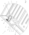
- FIG. 1 shows a temperature control arrangement 1 according to the invention, which comprises a battery housing 2 for accommodating battery modules for an electrically powered vehicle.
- the battery housing 2 is located underneath a vehicle interior and arranged between the axles of an electrically powered vehicle not shown here.
- the temperature control arrangement 1 further comprises a temperature control plate 3.
- the temperature control plate 3 is welded all the way around to the side of the battery housing 2 facing away from the vehicle, i.e. the underside of the battery housing 2, to form a first weld seam 4.
- the first weld seam 4 is located on the side of the temperature control plate 3 facing away from the battery housing 2.
- the temperature control plate 3 has a fluid channel 5, which has a channel opening 6 designed as a fluid inlet and a channel opening 7 designed as a fluid outlet.
- the temperature control plate 3 further comprises a connection opening 8 designed as a fluid inlet and a connection opening 9 designed as a fluid outlet.
- a cap 10 is joined to the temperature control plate 3, wherein the cap 10 connects the channel opening 6 designed as a fluid inlet and the connection opening 8 designed as a fluid inlet in a fluid-conducting manner by forming an overflow channel 11.
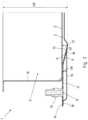
- the overflow channel 11 formed by the cap 10 and the temperature control plate 3 is particularly also shown in the sectional view in Figure 2
- a cap 10 is only arranged at the inlet openings 6, 8 and not at the outlet openings 7, 9.
- the tempering fluid can flow into the overflow channel 11 through the connection opening 8 designed as a fluid inlet and into the fluid channel 5 through the channel opening 6 designed as a fluid inlet.
- the heated or cooled tempering fluid flows through the channel opening 7 designed as a fluid outlet into the second overflow channel formed by the tempering plate 3 and the second cap (not shown) and from there through the connection opening 9 designed as a fluid outlet back into the fluid guide of the vehicle.
- a closed fluid circuit is thus formed for cooling or heating the battery modules located in the battery housing 2.
- the shape of the overflow channel 11 is essentially determined by the design of the cap 10.
- the cap 10, and thus the overflow channel 11, can thus be adapted to certain structural or fluidic specifications without the need to adapt the other components of the temperature control plate 3.
- the temperature control arrangement 1 according to the invention thus offers a high degree of flexibility with regard to the design and dimensioning of the fluid supply to the temperature control plate 3.
- the fluid channel 5 has a bulge 12 in front of the respective channel opening 6, 7.
- the fluid channel 5 has its maximum height hF.
- the height of the fluid channel 5 decreases linearly until the fluid channel 5 ends or the temperature control plate 3 comes into contact with the battery housing 2.
- a beveled area 13 is thus formed.
- the channel openings 6, 7 are arranged in the beveled area 13 of the fluid channel 5. This has proven to be particularly advantageous for the fluid guidance as well as for joining the cap 10.
- An angle ⁇ between 5° and 30°, particularly preferably between 15° and 25°, is preferably formed between the bevelled region 13 of the fluid channel 5 and the battery housing 2.
- the fluid channel 5 is limited by the battery housing 2.
- the tempering fluid (not shown in detail) flowing in the fluid channel 5 thus comes into direct contact with the battery housing 2. This ensures optimal heat transfer between the tempering fluid and the battery housing 2.
- FIG 2 further shows that the temperature control plate 3 and the cap 10 are located opposite each other at least in sections in the overflow channel 11.
- the temperature control plate 3 seals the fluid channel 5 laterally and on Figure 2
- the top of the fluid channel 5 is covered by the battery housing 2.
- the temperature control plate 3 rests against the battery housing 2 and is welded to it.
- the temperature control plate 3 covers the top of the overflow channel 11 formed by the cap 10. Relative to the flowing Tempering fluid thus causes a displacement of the tempering plate 3 from the upper side of the overflow channel 11 to the lower side of the fluid channel 5.
- the temperature control plate 3 has a projection 14 that projects beyond the battery housing 2. Both connection openings 8, 9 are arranged within the projection 14.
- connection openings 8, 9 are each connected to a connecting piece 15.
- the connecting pieces 15 are connected to a fluid guide of the motor vehicle (not shown in detail).
- the connecting pieces 15 each extend transversely to the side of the temperature control plate 3 facing the battery housing 2. In the embodiment shown here, the connecting pieces 15 run essentially parallel to a narrow side 16 of the battery housing 2.
- the temperature control arrangement 1 thus offers the further advantage that the design of the fluid supply and fluid discharge concept does not additionally increase the installation height hB of the temperature control arrangement 1.
- the cap 10 partially covers the first weld seam 4, whereby the cap 10 is welded fluid-tight to the temperature control plate 3 to form a second weld seam 17.
- the first weld seam 4 and the second weld seam 17 cross each other.
- the first weld seam 4 is visible through the cap 10 for illustration purposes.
- the cap 10 has a flattened portion 18 on its outer contour.
- the flattened portion 18 provides a suitable joining surface for welding the cap 10 to the temperature control plate 3.
- the fluid channel 5 has a maximum height hF and the cap 10 has a maximum height hK.
- the maximum height hK of the cap 10 is smaller in the embodiment shown than the maximum height hF of the fluid channel 5. This has also has the advantage that the installation height hB of the temperature control arrangement 1 is not additionally increased.
- the temperature control arrangement 1 has two caps 10, these can be connected with the same material or formed as one piece.
- a corresponding design is shown in Figure 3 shown.
- the two caps 10 are formed in one piece and connected to each other via a connecting web 19. This simplifies the arrangement of the caps 10 on the temperature control plate 3 and the joining process of the caps 10 to the temperature control plate 3.
Landscapes
- Engineering & Computer Science (AREA)
- Chemical & Material Sciences (AREA)
- Chemical Kinetics & Catalysis (AREA)
- Electrochemistry (AREA)
- General Chemical & Material Sciences (AREA)
- Manufacturing & Machinery (AREA)
- Mechanical Engineering (AREA)
- Sustainable Energy (AREA)
- Sustainable Development (AREA)
- Power Engineering (AREA)
- Transportation (AREA)
- Life Sciences & Earth Sciences (AREA)
- Automation & Control Theory (AREA)
- Aviation & Aerospace Engineering (AREA)
- Physics & Mathematics (AREA)
- Thermal Sciences (AREA)
- General Engineering & Computer Science (AREA)
- Secondary Cells (AREA)
- Battery Mounting, Suspending (AREA)
Abstract
Description
- Die vorliegende Erfindung betrifft eine Temperieranordnung mit den Merkmalen des Oberbegriffs von Anspruch 1.
- Die Erfindung betrifft weiterhin ein Verfahren zur Herstellung einer Temperieranordnung mit den Merkmalen des Anspruchs 14.
- Elektrisch angetriebene Fahrzeuge weisen üblicherweise Batteriemodule für die Bereitstellung der benötigten elektrischen Energie auf. Diese Batteriemodule sind zumeist in einem Batteriegehäuse angeordnet, welches zwischen den Achsen des Fahrzeugs angeordnet ist.
- Um die in den Batteriemodulen gespeicherte Energie optimal nutzen zu können, müssen die Batteriemodule in definierten Temperaturbereichen gehalten werden. So muss bei hoher Belastung die in den Batteriemodulen entstehende Wärme abgeführt werden, um ein Überhitzen der Batterie zu verhindern. Bei niedrigen Außentemperaturen oder als Vorbereitung für den Aufladevorgang der Batteriemodule kann auch ein Erwärmen erforderlich sein.
- Um eine entsprechende Temperierung der Batteriemodule zu gewährleisten, ist es im Stand der Technik bekannt Temperierplatten mit dem Batteriegehäuse zu verbinden. Die Temperierplatten weisen bevorzugt Fluidkanäle auf, durch die ein Temperierfluid strömt, welches Wärme von dem Batteriegehäuse und somit von dem in dem Batteriegehäuse angeordneten Batteriemodulen aufnehmen oder an diese abgeben kann.
- Hinsichtlich der Ausgestaltung der Fluidzuführung der Temperieranordnungen gibt es in Stand der Technik unterschiedliche Konzepte. Beispielsweise offenbart die
DE 10 2020 113 425 B3 ein Verbindungselement, welches mit einer Kanalöffnung des Fluidkanals und mit einer Fluidführung des Kraftfahrzeugs verbunden ist. Das Verbindungselement hat jedoch zwei wesentliche Nachteile. Zum einen gestaltet sich die Kopplung des Verbindungselements mit der Temperierplatte aufwendig und zum anderen ist die Fertigung des Verbindungselements aufgrund seiner Komplexität kostenaufwendig. - Ausgehend vom Stand der Technik ist daher die Aufgabe der vorliegenden Erfindung, eine verbesserte Temperieranordnung sowie ein Verfahren zu deren Herstellung bereitzustellen.
- Der gegenständliche Teil dieser Aufgabe wird durch eine Temperieranordnung gemäß Anspruch 1 gelöst. Den verfahrenstechnischen Teil der Aufgabe löst das Verfahren zur Herstellung einer Temperieranordnung gemäß Anspruch 14.
- Vorteilhafte Ausgestaltungen und Weiterbildungen der erfindungsgemäßen Temperieranordnung sind Gegenstand der abhängigen Ansprüche.
- Die erfindungsgemäße Temperieranordnung umfasst ein Batteriegehäuse zur Aufnahme von Batteriemodulen für ein elektrisch angetriebenes Fahrzeug. Unter Batteriemodulen werden im Rahmen der Erfindung auch Batterieelemente und/oder Batteriezellen verstanden.
- Weiterhin umfasst die Temperieranordnung eine Temperierplatte, die mit dem Batteriegehäuse verbunden ist. Über die Temperierplatte können die im Batteriegehäuse angeordneten Batteriemodule temperiert, mithin gekühlt oder erwärmt werden. Dazu weist die Temperierplatte wenigstens einen Fluidkanal auf, wobei der Fluidkanal wenigstens eine Kanalöffnung aufweist, über die ein Temperierfluid in den Fluidkanal ein- bzw. ausgeführt werden kann.
- Die Temperierplatte weist wenigstens eine Anschlussöffnung auf. Über die Anschlussöffnung kann die Temperierplatte mit einer Fluidführung des Kraftfahrzeugs verbunden werden. Erfindungswesentlich ist, dass eine Kappe mit der Temperierplatte gefügt ist, wobei die Kappe die Kanalöffnung und die Anschlussöffnung fluidleitend durch Ausbildung eines Überströmkanals verbindet. Das von der Fluidführung bereitgestellte Temperierfluid kann somit durch die Anschlussöffnung, den Überströmkanal und die Kanalöffnung in den Fluidkanal strömen. Eine umgekehrte Strömungsrichtung ist ebenfalls möglich.
- Erfindungsgemäß liegen sich die Temperierplatte und die Kappe zumindest abschnittsweise in dem Überströmkanal gegenüber. Die Formgebung des Überströmkanals ist somit wesentlich von der Ausgestaltung der Kappe abhängig. Die Kappe, und damit der Überströmkanal, kann somit an bestimmte bautechnische oder strömungstechnische Vorgaben angepasst werden, ohne dass eine Anpassung der übrigen Bauteilkomponenten der Temperierplatte erforderlich ist. Die erfindungsgemäße Temperieranordnung bietet somit ein hohes Maß an Flexibilität im Hinblick auf die Gestaltung und Dimensionierung der Fluidzuführung und -abführung der Temperierplatte.
- Die Kappe ist dabei bevorzugt einstückig aus einem Aluminium oder Edelstahlblech warm- oder kaltgeformt. Es handelt sich somit um ein einfach und kostengünstig herzustellendes Bauteil. Die Kappe ist vorzugsweise derart geformt, dass die äußere Kontur der Kappe bei erfindungsgemäßer Anordnung der Kappe auf der Temperierplatte nahtlos, mithin ohne Ausbildung eines Spalts, auf der Temperierplatte aufliegt. Dies vereinfacht den anschließenden Fügeprozess und sorgt für einen fluiddichten Sitz der Kappe auf der Temperierplatte.
- Vorzugsweise weist die Kappe an ihrer äußeren Kontur eine Abflachung auf. Die Abflachung bietet eine geeignete Fügefläche für die Verschweißung der Kappe mit der Tem perierplatte.
- Die Temperierplatte und das Batteriegehäuse sind insbesondere aus Aluminium und/oder Edelstahl ausgebildet.
- Bevorzugt wird der Fluidkanal durch das Batteriegehäuse begrenzt. Dies hat den Vorteil, dass das durch den Fluidkanal strömende Temperierungsfluid direkt mit dem Batteriegehäuse in Kontakt kommt. So wird ein optimaler Wärmeübergang zwischen dem Batteriegehäuse und dem Temperierfluid gewährleistet. Ein weiterer Vorteil ist, dass die Temperierplatte aus einem Werkstück bzw. Blech ausgebildet werden kann. Die Fluidkanäle der Temperierplatte können über einen Warm- oder einen Kaltformvorgang ausgebildet werden.
- Alternativ ist die Temperierplatte als eine zumindest abschnittsweise doppelwandige Temperierplatte ausgebildet. In diesem Fall weist die Temperierplatte eine obere Platte und eine untere Platte auf, wobei der Fluidkanal durch die obere Platte begrenzt ist. Die Kanalöffnung ist bevorzugt in der oberen Platte ausgebildet. Die untere Platte der Temperierplatte liegt am Batteriegehäuse an. Diese Ausführungsvariante hat den Vorteil, dass das Temperierfluid nicht direkt mit dem Batteriegehäuse in Kontakt kommt. Die Wärmeübertragung erfolgt somit zwischen der unteren Platte und dem Batteriegehäuse. Dies kann beispielsweise vorteilhaft sein, wenn die Oberfläche des Batteriegehäuses nicht für einen Kontakt mit dem Temperierfluid ausgelegt ist.
- Vorzugsweise ist die Temperierplatte umlaufend mit dem Batteriegehäuse unter Ausbildung einer ersten Schweißnaht verschweißt. Dabei befindet sich die erste Schweißnaht auf der dem Batteriegehäuse abgewandten Seite der Temperierplatte. Mittels einer entsprechenden Schweißverbindung kann ein sicherer Halt zwischen der Temperierplatte und dem Batteriegehäuse gewährleistet werden. Zudem handelt es sich um ein kostengünstiges Fügeverfahren.
- In einer vorteilhaften Ausführungsvariante der Temperieranordnung bedeckt die Kappe die erste Schweißnaht, wobei die Kappe unter Ausbildung einer zweiten Schweißnaht fluiddicht mit der Temperierplatte verschweißt ist. Dies hat zur Folge, dass sich die erste Schweißnaht und die zweite Schweißnaht kreuzen. Die Tatsache, dass die Temperierplatte mit dem Batteriegehäuse verschweißt wird, bevor die Kappe auf der Temperierplatte angeordnet wird, hat den Vorteil, dass eine sichere Verbindung zwischen dem Batteriegehäuse und der Temperierplatte auch im Bereich der Kappe gewährleistet ist. Die äußere Kontur der Kappe kann zudem eine Aussparung aufweisen, dergestalt, dass eine etwaige über die Temperierplatte überstehende Wulst der ersten Schweißnaht bei Anordnung der Kappe auf der Temperierplatte in der Aussparung liegt.
- Bevorzugt weist die Temperierplatte einen Vorsprung auf, der über das Batteriegehäuse hinausragt, wobei die wenigstens eine Anschlussöffnung innerhalb des Vorsprungs angeordnet ist. Somit kann die Fluidführung mit der Anschlussöffnung verbunden werden, ohne dass dies eine Erhöhung der Aufbauhöhe der Temperieranordnung zur Folge hat.
- Dazu ist vorzugsweise ein Verbindungsstutzen mit der Anschlussöffnung verbunden. Über den Verbindungsstutzen wird die Anschlussöffnung mit der Fluidführung des Kraftfahrzeugs verbunden. Der Verbindungsstutzen erstreckt sich dabei insbesondere quer zu der dem Batteriegehäuse zugewandten Seite der Temperierplatte. Im Gegensatz zu gängigen Lösungen im Stand der Technik ragt der Verbindungsstutzen somit nicht über das Batteriegehäuse hinaus, sondern verläuft ausgehend von der Anschlussöffnung im Wesentlichen parallel zu einer Schmalseite des Batteriegehäuses. Die Aufbauhöhe der Temperieranordnung wird somit durch den Anschlussstutzen bzw. die daran angeschlossene Fluidführung nicht weiter erhöht. Diese Ausgestaltung löst somit eine weitere Aufgabe, nämlich ausgehend vom Stand der Technik eine Temperieranordnung mit einer möglichst geringen Aufbauhöhe bereitzustellen.
- Bevorzugt weist die Temperierplatte zwei Anschlussöffnungen auf. In diesem Fall ist eine Anschlussöffnung als Fluideinlass und eine Anschlussöffnung als Fluidauslass ausgebildet. Weiterhin Bevorzugt weist der Fluidkanal zwei Kanalöffnungen auf, wobei eine Kanalöffnung als Fluideinlass und eine Kanalöffnung als Fluidauslass ausgebildet ist. In dieser Ausführungsvariante kann die Temperieranordnung zwei Kappen aufweisen. Eine Kappe verbindet die als Fluideinlass ausgebildete Anschlussöffnung mit der als Fluideinlass ausgebildeten Kanalöffnung fluidtechnisch. Die andere Kappe verbindet die als Fluidauslass ausgebildete Anschlussöffnung mit der als Fluidauslass ausgebildeten Kanalöffnung fluidtechnisch. Das Temperierfluid kann somit durch die als Fluideinlass ausgebildete Anschlussströmung in den Überströmkanal einströmen und durch die als Fluideinlass ausgebildete Kanalöffnung in den Fluidkanal gelangen. Nach der Temperierung des Batteriegehäuses strömt das erwärmte oder gekühlte Temperierfluid durch die als Fluidauslass ausgebildete Kanalöffnung in den durch die Temperierplatte und die zweite Kappe ausgebildeten zweiten Überströmkanal und von diesem durch die als Fluidauslass ausgebildete Anschlussöffnung zurück in die Fluidführung des Fahrzeugs. Mithin ist ein abgeschlossener Fluidkreislauf ausgebildet.
- Weist die Temperieranordnung zwei Kappen auf, können diese materialeinheitlich verbunden sein. Dies vereinfacht zum einen die Anordnung der Kappen und zum anderen den Fügeprozess mit der Temperierplatte.
- Sowohl der Fluidkanal als auch die Kappe weisen eine maximale Bauhöhe auf. Bevorzugt ist die maximale Bauhöhe der Kappe kleiner oder gleich der maximalen Bauhöhe des Fluidkanals. So wird durch die Kappe die Aufbauhöhe der Temperieranordnung nicht zusätzlich erhöht.
- Vorzugsweise weist der Fluidkanal vor der Kanalöffnung eine Ausbuchtung auf. In dieser Ausbuchtung liegt bevorzugt die maximale Bauhöhe des Fluidkanals. Ausgehend vom Punkt der maximalen Bauhöhe nimmt diese insbesondere linear ab, bis der Fluidkanal endet bzw. die Temperierplatte mit dem Batteriegehäuse zur Anlage kommt. Mithin ist ein abgeschrägter Bereich des Fluidkanals ausgebildet. Die Kanalöffnung ist bevorzugt in diesem angeschrägten Bereich des Fluidkanals angeordnet. Dies hat sich besonders Vorteilhaft für die Fluidführung als auch für das Fügen der Kappe herausgestellt.
- Zwischen dem abgeschrägten Bereich des Fluidkanals und dem Batteriegehäuse ist bevorzugt einen Winkel zwischen 5° und 30°, besonders bevorzugt zwischen 15° und 25° ausgebildet.
- Die erfindungsgemäße Temperieranordnung kann mit einem Verfahren hergestellt werden, welches die nachfolgend beschriebenen Schritte umfasst.
- Zunächst wird das Batteriegehäuse bereitgestellt. Anschließend wird die Temperierplatte an dem Batteriegehäuse angeordnet, wobei die Temperierplatte einen Fluidkanal aufweist, der Fluidkanal eine Kanalöffnung aufweist und die Temperierplatte eine Anschlussöffnung aufweist.
- In einem nächsten Schritt wird die Temperierplatte umlaufend mit dem Batteriegehäuse unter Ausbildung der ersten Schweißnaht verschweißt. Die Schweißnaht befindet sich auf der dem Batteriegehäuse abgewandten Seite der Temperierplatte.
- Anschließend wird die Kappe auf der Temperierplatte angeordnet, wobei die Kappe die erste Schweißnaht teilweise bedeckt und die Kappe die Kanalöffnung und die Anschlussöffnung unter Ausbildung eines Überströmkanals fluidtechnisch verbindet.
- Die Kappe wird umlaufend und fluiddicht mit der Temperierplatte unter Ausbildung der zweiten Schweißnaht verschweißt. Dies hat zur Folge, dass sich die erste Schweißnaht und die zweite Schweißnaht kreuzen.
- Die Erfindung ist nachfolgend anhand von in den Zeichnungen dargestellten Ausführungsbeispielen näher beschrieben. Es zeigen:
- Figur 1
- eine erfindungsgemäße Temperieranordnung in einer Perspektive,
- Figur 2
- die erfindungsgemäße Temperieranordnung in einer Schnittdarstellung und
- Figur 3
- eine Ausführungsvariante der Kappe.
- In den Figuren werden für gleiche oder funktionell einander entsprechende Bauteile bzw. Bauteilkomponenten die gleichen Bezugszeichen verwendet, auch wenn aus Gründen der Vereinfachung auf eine wiederholte Beschreibung verzichtet wird.
-
Figur 1 zeigt eine erfindungsgemäße Temperieranordnung 1, welche ein Batteriegehäuse 2 zur Aufnahme von Batteriemodulen für ein elektrisch angetriebenes Fahrzeug umfasst. Das Batteriegehäuse 2 ist unterhalb eines Fahrzeuginnenraums und zwischen den Achsen eines hier nicht dargestellten elektrisch angetriebenen Fahrzeugs angeordnet. - Die Temperieranordnung 1 umfasst ferner eine Temperierplatte 3. Die Temperierplatte 3 ist umlaufend mit der dem Fahrzeug abgewandten Seite des Batteriegehäuses 2, mithin der Unterseite des Batteriegehäuses 2, unter Ausbildung einer ersten Schweißnaht 4 verschweißt. Die erste Schweißnaht 4 befindet sich auf der dem Batteriegehäuse 2 abgewandten Seite der Temperierplatte 3.
- Die Temperierplatte 3 weist einen Fluidkanal 5 auf, welcher eine als Fluideinlass ausgebildete Kanalöffnung 6 und eine als Fluidauslass ausgebildete Kanalöffnung 7 aufweist.
- Die Temperierplatte 3 weist weiterhin eine als Fluideinlass ausgebildete Anschlussöffnung 8 sowie eine als Fluidauslass ausgebildete Anschlussöffnung 9 auf. Erfindungsgemäß ist eine Kappe 10 mit der Temperierplatte 3 gefügt, wobei die Kappe 10 die als Fluideinlass ausgebildete Kanalöffnung 6 und die als Fluideinlass ausgebildete Anschlussöffnung 8 fluidleitend durch Ausbildung eines Überströmkanals 11 verbindet. Der durch die Kappe 10 und die Temperierplatte 3 ausgebildete Überströmkanal 11 ist insbesondere auch in der Schnittdarstellung in
Figur 2 zu sehen. Aus Darstellungsgründen ist in dem gezeigten Ausführungsbeispiel inFigur 1 lediglich an den Einlassöffnungen 6, 8 eine Kappe 10 angeordnet und nicht an den Auslassöffnungen 7, 9. - Das in den Figuren nicht dargestellte Temperierfluid kann durch die als Fluideinlass ausgebildete Anschlussöffnung 8 in den Überströmkanal 11 einströmen und durch die als Fluideinlass ausgebildete Kanalöffnung 6 in den Fluidkanal 5 gelangen. Nach der Temperierung des Batteriegehäuses 2 strömt das erwärmte oder gekühlte Temperierfluid durch die als Fluidauslass ausgebildete Kanalöffnung 7 in den durch die Temperierplatte 3 und die nicht dargestellte zweite Kappe ausgebildeten zweiten Überströmkanal und von diesem durch die als Fluidauslass ausgebildete Anschlussöffnung 9 zurück in die Fluidführung des Fahrzeugs. Mithin ist ein abgeschlossener Fluidkreislauf zum Kühlen oder Erwärmen der in dem Batteriegehäuse 2 befindlichen Batteriemodule ausgebildet.
- Die Formgebung des Überströmkanals 11 ist wesentlich von der Ausgestaltung der Kappe 10 geprägt. Die Kappe 10, und damit der Überströmkanal 11, kann somit an bestimmte bautechnische oder strömungstechnische Vorgaben angepasst werden, ohne dass eine Anpassung der übrigen Bauteilkomponenten der Temperierplatte 3 erforderlich ist. Die erfindungsgemäße Temperieranordnung 1 bietet somit ein hohes Maß an Flexibilität im Hinblick auf die Gestaltung und Dimensionierung der Fluidzuführung der Temperierplatte 3.
- Der Fluidkanal 5 weist vor der jeweiligen Kanalöffnung 6, 7 eine Ausbuchtung 12 auf. In dieser Ausbuchtung 12 weist der Fluidkanals 5 seine maximale Bauhöhe hF auf. Ausgehend vom Punkt der maximalen Bauhöhe hF nimmt die Bauhöhe des Fluidkanals 5 linear ab, bis der Fluidkanal 5 endet bzw. die Temperierplatte 3 mit dem Batteriegehäuse 2 zur Anlage kommt. Mithin ist ein abgeschrägter Bereich 13 ausgebildet. Die Kanalöffnungen 6, 7 sind in dem abgeschrägten Bereich 13 des Fluidkanals 5 angeordnet. Dies hat sich besonders Vorteilhaft für die Fluidführung als auch für das Fügen der Kappe 10 herausgestellt.
- Zwischen dem abgeschrägten Bereich 13 des Fluidkanals 5 und dem Batteriegehäuse 2 ist bevorzugt einen Winkel α zwischen 5° und 30°, besonders bevorzugt zwischen 15° und 25° ausgebildet.
- Der Fluidkanal 5 wird durch das Batteriegehäuse 2 begrenzt. Das im Fluidkanal 5 strömende und nicht näher dargestellte Temperierfluid kommt somit direkt mit dem Batteriegehäuse 2 in Kontakt. Dies sorgt für eine optimale Wärmeübertragung zwischen dem Temperierfluid und dem Batteriegehäuse 2.
-
Figur 2 zeigt ferner, dass sich die Temperierplatte 3 und die Kappe 10 erfindungsgemäß zumindest abschnittsweise in dem Überströmkanal 11 gegenüberliegen. Die Temperierplatte 3 dichtet den Fluidkanal 5 seitlich und aufFigur 2 bezogen nach unten hin ab. Die Oberseite des Fluidkanals 5 wird durch das Batteriegehäuse 2 abgedeckt. Auf der dem Fluidkanal 5 abgewandten Seite des abgeschrägten Bereichs 13 liegt die Temperierplatte 3 am Batteriegehäuse 2 an und ist mit diesem verschweißt. Die Temperierplatte 3 deckt hier die Oberseite des durch die Kappe 10 ausgebildeten Überströmkanal 11 ab. Relativ zum strömenden Temperierfluid findet somit eine Verlagerung der Temperierplatte 3 von der Oberseite des Überströmkanals 11 zur Unterseite des Fluidkanals 5 statt. - Die Temperierplatte 3 weist einen Vorsprung 14 auf, der über das Batteriegehäuse 2 hinausragt. Beide Anschlussöffnungen 8, 9 sind innerhalb des Vorsprungs 14 angeordnet.
- Die Anschlussöffnungen 8, 9 sind jeweils mit einem Verbindungsstutzen 15 verbunden. Die Verbindungsstutzen 15 sind mit einer nicht näher dargestellten Fluidführung des Kraftfahrzeugs verbunden.
- Die Verbindungsstutzen 15 erstrecken sich jeweils quer zu der dem Batteriegehäuse 2 zugewandten Seite der Temperierplatte 3. Im hier gezeigten Ausführungsbeispiel verlaufen die Verbindungsstutzen 15 im Wesentlichen parallel zu einer Schmalseite 16 des Batteriegehäuses 2. Die Temperieranordnung 1 bietet somit den weiteren Vorteil, dass die die Ausgestaltung des Fluidzuführungs- und Fluidabführungskonzepts die Aufbauhöhe hB der Temperieranordnung 1 nicht zusätzlich erhöht.
- Die Kappe 10 bedeckt die erste Schweißnaht 4 teilweise, wobei die Kappe 10 unter Ausbildung einer zweiten Schweißnaht 17 fluiddicht mit der Temperierplatte 3 verschweißt ist. Die erste Schweißnaht 4 und die zweite Schweißnaht 17 kreuzen sich. In
Figur 1 ist die erste Schweißnaht 4 aus Darstellungsgründen durch die Kappe 10 hindurch sichtbar. Durch die nachträgliche Anordnung der Kappe 10 auf der ersten Schweißnaht 4 kann eine sichere Verbindung der Temperierplatte 3 mit dem Batteriegehäuse 2 auch im Bereich des Überströmkanals 11 sichergestellt werden. - Die Kappe 10 weist an ihrer äußeren Kontur eine Abflachung 18 auf. Die Abflachung 18 bietet eine geeignete Fügefläche für die Verschweißung der Kappe 10 mit der Temperierplatte 3.
- Der Fluidkanal 5 weist eine maximale Bauhöhe hF auf und die Kappe 10 eine maximale Bauhöhe hK. Die maximale Bauhöhe hK der Kappe 10 ist im gezeigten Ausführungsbeispiel kleiner als die maximale Bauhöhe hF des Fluidkanals 5. Dies hat ebenfalls den Vorteil, dass die Aufbauhöhe hB der Temperieranordnung 1 nicht zusätzlich erhöht wird.
- Weist die Temperieranordnung 1 zwei Kappen 10 auf, können diese materialeinheitlich verbunden oder einstückig ausgebildet sein. Eine entsprechende Ausgestaltung ist in
Figur 3 gezeigt. Die zwei Kappen 10 sind einstückig ausgebildet und über einen Verbindungssteg 19 miteinander verbunden. Dies vereinfacht zum einen die Anordnung der Kappen 10 auf der Temperierplatte 3 und zum anderen den Fügeprozess der Kappen 10 mit der Temperierplatte 3. -
- 1 -
- Temperieranordnung
- 2 -
- Batteriegehäuse
- 3 -
- Temperierplatte
- 4 -
- erste Schweißnaht
- 5 -
- Fluidkanal
- 6 -
- Kanalöffnung
- 7 -
- Kanalöffnung
- 8 -
- Anschlussöffnung
- 9 -
- Anschlussöffnung
- 10 -
- Kappe
- 11 -
- Überströmkanal
- 12 -
- Ausbuchtung
- 13 -
- abgeschrägter Bereich
- 14 -
- Vorsprung
- 15 -
- Verbindungsstutzen
- 16 -
- Schmalseite
- 17 -
- zweite Schweißnaht
- 18 -
- Abflachung
- 19 -
- Verbindungssteg
- hB -
- Aufbauhöhe
- hK -
- maximale Höhe Fluidkanal
- hF -
- maximale Höhe Kappe
Claims (14)
- Temperieranordnung (1) umfassendein Batteriegehäuse (2) zur Aufnahme von Batteriemodulen für ein elektrisch angetriebenes Fahrzeug undeine Temperierplatte (3), wobei die Temperierplatte (3) wenigstens einen Fluidkanal (5) aufweist und der Fluidkanal (5) wenigstens eine Kanalöffnung (6, 7) aufweist, wobei die Temperierplatte (3) mit dem Batteriegehäuse (2) verbunden ist,dadurch gekennzeichnet, dassdie Temperierplatte (3) wenigstens eine Anschlussöffnung (8, 9) aufweist, wobei eine Kappe (10) mit der Temperierplatte (3) gefügt ist und die Kappe (10) die Kanalöffnung (6, 7) und die Anschlussöffnung (8, 9) fluidleitend durch Ausbildung eines Überströmkanals (11) verbindet, wobei sich die Temperierplatte (3) und die Kappe (10) zumindest abschnittsweise in dem Überströmkanal (11) gegenüberliegen.
- Temperieranordnung (1) nach Anspruch 1, dadurch gekennzeichnet, dass der Fluidkanal (5) durch das Batteriegehäuse (2) begrenzt wird.
- Temperieranordnung (1) nach Anspruch 1, dadurch gekennzeichnet, dass die Temperierplatte (3) als eine zumindest abschnittsweise doppelwandige Temperierplatte (3) ausgebildet ist, welche eine obere Platte und eine untere Platte aufweist, wobei der Fluidkanal (5) durch die obere Platte und die untere Platte begrenzt ist und die Kanalöffnung (6, 7) in der oberen Platte ausgebildet ist.
- Temperieranordnung (1) nach einem der Ansprüche 1 bis 3, dadurch gekennzeichnet, dass die Temperierplatte (3) umlaufend mit dem Batteriegehäuse (2) unter Ausbildung einer ersten Schweißnaht (4) verschweißt ist und sich die erste Schweißnaht (4) auf der dem Batteriegehäuse (2) abgewandten Seite der Temperierplatte (3) befindet.
- Temperieranordnung (1) nach Anspruch 4, dadurch gekennzeichnet, dass die Kappe (10) die erste Schweißnaht (4) teilweise bedeckt, wobei die Kappe (10) unter Ausbildung einer zweiten Schweißnaht (17) fluiddicht mit der Temperierplatte (3) verschweißt ist, dergestalt, dass sich die erste Schweißnaht (4) und die zweite Schweißnaht (17) kreuzen.
- Temperieranordnung (1) nach einem der Ansprüche 1 bis 5, dadurch gekennzeichnet, dass die Temperierplatte (3) einen Vorsprung (14) aufweist, der über das Batteriegehäuse (2) hinausragt, wobei die wenigstens eine Anschlussöffnung (8, 9) innerhalb des Vorsprungs (14) angeordnet ist.
- Temperieranordnung (1) nach einem der Ansprüche 1 bis 6, dadurch gekennzeichnet, dass die Temperierplatte (3) zwei Anschlussöffnungen (8, 9) aufweist, wobei eine Anschlussöffnung (8) als Fluideinlass und eine Anschlussöffnung (9) als Fluidauslass ausgebildet ist.
- Temperieranordnung (1) nach einem der Ansprüche 1 bis 7, dadurch gekennzeichnet, dass der Fluidkanal (5) zwei Kanalöffnungen (6, 7) aufweist, wobei eine Kanalöffnung (6) als Fluideinlass und eine Kanalöffnung (7) als Fluidauslass ausgebildet ist.
- Temperieranordnung (1) nach Anspruch 7 und 8, dadurch gekennzeichnet, dass die Temperieranordnung (1) zwei Kappen (10) aufweist, wobei eine Kappe (10) die als Fluideinlass ausgebildete Anschlussöffnung (8) mit der als Fluideinlass ausgebildeten Kanalöffnung (6) fluidtechnisch verbindet und eine Kappe (10) die als Fluidauslass ausgebildete Anschlussöffnung (9) mit der als Fluidauslass ausgebildeten Kanalöffnung (7) fluidtechnisch verbindet.
- Temperieranordnung (1) nach Anspruch 9, dadurch gekennzeichnet, dass die zwei Kappen (10) materialeinheitlich verbunden sind.
- Temperieranordnung (1) nach einem der Ansprüche 1 bis 10, dadurch gekennzeichnet, dass ein Verbindungsstutzen (15) mit der Anschlussöffnung (8, 9) verbunden ist.
- Temperieranordnung (1) nach Anspruch 11, dadurch gekennzeichnet, dass sich der Verbindungsstutzen (15) quer zu der dem Batteriegehäuse (2) zugewandten Seite der Temperierplatte (3) erstreckt.
- Temperieranordnung (1) nach einem der Ansprüche 1 bis 12, dadurch gekennzeichnet, dass der Fluidkanal (5) eine maximale Bauhöhe (hF) aufweist und die Kappe (10) eine maximale Bauhöhe (hK) aufweist, wobei die maximale Bauhöhe der Kappe (10) kleiner oder gleich der maximalen Bauhöhe des Fluidkanals (5) ist.
- Verfahren zur Herstellung einer Temperieranordnung (1) gemäß einem der Ansprüche 1 bis 13, wobei das Verfahren die folgenden Schritte umfasst:• Bereitstellen eines Batteriegehäuses (2) zur Aufnahme von Batteriemodulen für ein elektrisch angetriebenes Fahrzeug,einer Temperierplatte (3), wobei die Temperierplatte (3) einen Fluidkanal (5) aufweist, der Fluidkanal (5) eine Kanalöffnung (6, 7) aufweist und die Temperierplatte (3) eine Anschlussöffnung (8, 9) aufweist undeiner Kappe (10),• Anordnung der Temperierplatte (3) an dem Batteriegehäuse (2),• umlaufende Verschweißung der Temperierplatte (3) mit dem Batteriegehäuse (2) unter Ausbildung einer ersten Schweißnaht (4), wobei sich die erste Schweißnaht (4) auf der dem Batteriegehäuse (2) abgewandten Seite der Temperierplatte (3) befindet,• Anordnung der Kappe (10) auf der Temperierplatte (3), wobei die Kappe (10) die erste Schweißnaht (4) teilweise bedeckt und die Kappe (10) die Kanalöffnung (6, 7) und die Anschlussöffnung (8, 9) unter Ausbildung eines Überströmkanals (11) fluidtechnisch verbindet und• umlaufende fluiddichte Verschweißung der Kappe (10) mit der Temperierplatte (3) unter Ausbildung einer zweiten Schweißnaht (17), dergestalt, dass sich die erste Schweißnaht (4) und die zweite Schweißnaht (17) kreuzen.
Priority Applications (5)
| Application Number | Priority Date | Filing Date | Title |
|---|---|---|---|
| EP23173842.8A EP4464547B1 (de) | 2023-05-17 | 2023-05-17 | Temperieranordnung und verfahren zur herstellung einer temperieranordnung |
| ES23173842T ES3017335T3 (en) | 2023-05-17 | 2023-05-17 | Temperature control arrangement and method for producing a temperature control arrangement |
| HUE23173842A HUE071062T2 (hu) | 2023-05-17 | 2023-05-17 | Hõmérséklet-szabályozó berendezés és eljárás a hõmérséklet-szabályozó berendezés elõállítására |
| US18/666,324 US20240387904A1 (en) | 2023-05-17 | 2024-05-16 | Temperature control arrangement and method of manufacturing a temperature control arrangement |
| CN202410605635.8A CN119009242A (zh) | 2023-05-17 | 2024-05-16 | 调温装置和用于制造调温装置的方法 |
Applications Claiming Priority (1)
| Application Number | Priority Date | Filing Date | Title |
|---|---|---|---|
| EP23173842.8A EP4464547B1 (de) | 2023-05-17 | 2023-05-17 | Temperieranordnung und verfahren zur herstellung einer temperieranordnung |
Publications (2)
| Publication Number | Publication Date |
|---|---|
| EP4464547A1 true EP4464547A1 (de) | 2024-11-20 |
| EP4464547B1 EP4464547B1 (de) | 2025-03-05 |
Family
ID=86386895
Family Applications (1)
| Application Number | Title | Priority Date | Filing Date |
|---|---|---|---|
| EP23173842.8A Active EP4464547B1 (de) | 2023-05-17 | 2023-05-17 | Temperieranordnung und verfahren zur herstellung einer temperieranordnung |
Country Status (5)
| Country | Link |
|---|---|
| US (1) | US20240387904A1 (de) |
| EP (1) | EP4464547B1 (de) |
| CN (1) | CN119009242A (de) |
| ES (1) | ES3017335T3 (de) |
| HU (1) | HUE071062T2 (de) |
Citations (5)
| Publication number | Priority date | Publication date | Assignee | Title |
|---|---|---|---|---|
| US10608305B2 (en) * | 2017-01-19 | 2020-03-31 | Dana Canada Corporation | Counter-flow heat exchanger with in-line fittings |
| DE102020107366A1 (de) * | 2020-03-18 | 2021-09-23 | Audi Aktiengesellschaft | Batteriegehäuse für eine Traktionsbatterie eines Kraftfahrzeugs, entsprechende Traktionsbatterie sowie ein Verfahren zum Herstellen eines Batteriegehäuses |
| US11155150B2 (en) * | 2018-03-01 | 2021-10-26 | Shape Corp. | Cooling system integrated with vehicle battery tray |
| DE102020113425B3 (de) | 2020-05-18 | 2021-11-18 | Benteler Automobiltechnik Gmbh | Temperiervorrichtung für Batteriemodule |
| US11239512B2 (en) * | 2017-05-16 | 2022-02-01 | Dana Canada Corporation | Counterflow heat exchanger with side entry fittings |
-
2023
- 2023-05-17 EP EP23173842.8A patent/EP4464547B1/de active Active
- 2023-05-17 ES ES23173842T patent/ES3017335T3/es active Active
- 2023-05-17 HU HUE23173842A patent/HUE071062T2/hu unknown
-
2024
- 2024-05-16 US US18/666,324 patent/US20240387904A1/en active Pending
- 2024-05-16 CN CN202410605635.8A patent/CN119009242A/zh active Pending
Patent Citations (5)
| Publication number | Priority date | Publication date | Assignee | Title |
|---|---|---|---|---|
| US10608305B2 (en) * | 2017-01-19 | 2020-03-31 | Dana Canada Corporation | Counter-flow heat exchanger with in-line fittings |
| US11239512B2 (en) * | 2017-05-16 | 2022-02-01 | Dana Canada Corporation | Counterflow heat exchanger with side entry fittings |
| US11155150B2 (en) * | 2018-03-01 | 2021-10-26 | Shape Corp. | Cooling system integrated with vehicle battery tray |
| DE102020107366A1 (de) * | 2020-03-18 | 2021-09-23 | Audi Aktiengesellschaft | Batteriegehäuse für eine Traktionsbatterie eines Kraftfahrzeugs, entsprechende Traktionsbatterie sowie ein Verfahren zum Herstellen eines Batteriegehäuses |
| DE102020113425B3 (de) | 2020-05-18 | 2021-11-18 | Benteler Automobiltechnik Gmbh | Temperiervorrichtung für Batteriemodule |
Also Published As
| Publication number | Publication date |
|---|---|
| ES3017335T3 (en) | 2025-05-12 |
| HUE071062T2 (hu) | 2025-07-28 |
| CN119009242A (zh) | 2024-11-22 |
| US20240387904A1 (en) | 2024-11-21 |
| EP4464547B1 (de) | 2025-03-05 |
Similar Documents
| Publication | Publication Date | Title |
|---|---|---|
| EP3295509B1 (de) | Energiespeicher eines kraftfahrzeugs | |
| EP2575418B1 (de) | Elektronikkühler und Verfahren zum Herstellen eines Elektronikkühlers | |
| DE69503972T2 (de) | Verstärkte Endplatte für Wärmetauscher | |
| DE10130369A1 (de) | Vorrichtung zum Kühlen einer Fahrzeugeinrichtung, insbesondere Batterie oder Brennstoffzelle | |
| DE102021124621A1 (de) | Kühlkörper | |
| DE202019102427U1 (de) | Plattenartiger Fluidbehälter | |
| EP4464547B1 (de) | Temperieranordnung und verfahren zur herstellung einer temperieranordnung | |
| WO2020127097A1 (de) | Temperierelement, batteriespeichervorrichtung, verfahren zum herstellen eines temperierelements und verfahren zum herstellen einer batteriespeichervorrichtung | |
| DE102018124053B4 (de) | Hochvolt (HV)-Batterie mit einer Kühleinrichtung zum Kühlen elektrischer Module derselben | |
| DE19750067A1 (de) | Verfahren zum Fügen eines Bauteils an einen Hohlkörper und dadurch herstellbarer Halter-Rohrelement-Komplex | |
| DE102005002063A1 (de) | Stapelscheiben -Wärmetauscher | |
| DE102019209155A1 (de) | Energiespeicheranordnung | |
| EP4160788A1 (de) | Batteriemodul einer traktionsbatterie eines kraftfahrzeugs und verfahren zum herstellen desselben | |
| EP1890102A1 (de) | Gewölbter Bodenteil für einen Sammelkasten eines Wärmeaustauschers | |
| EP3088834B1 (de) | Wärmeübertrager | |
| EP2994712B1 (de) | Wärmeübertrager | |
| DE102021210826A1 (de) | Kühler mit zwei weitgehend parallelen Strömungsräumen und drei weitgehend parallelen Platten | |
| EP4425085B1 (de) | Wärmeübertragerplatte | |
| DE102021111737B4 (de) | Batteriezelle | |
| EP4421437B1 (de) | Wärmeübertragerplatte und verfahren zur herstellung einer wärmeübertragerplatte | |
| EP2175211A2 (de) | Solarabsorbermodul und Wärmetauscher | |
| DE102014217546A1 (de) | Kühl- und/oder Heizvorrichtung eines Batteriemoduls | |
| DE102023129267A1 (de) | Wärmeübertrager mit zwei Arten von Platten | |
| DE102023114998A1 (de) | Kühlbauteil und Verfahren zur Herstellung desselben | |
| DE102023211570A1 (de) | Turbulenzblech und Stapelscheibenwärmeübertrager |
Legal Events
| Date | Code | Title | Description |
|---|---|---|---|
| PUAI | Public reference made under article 153(3) epc to a published international application that has entered the european phase |
Free format text: ORIGINAL CODE: 0009012 |
|
| STAA | Information on the status of an ep patent application or granted ep patent |
Free format text: STATUS: REQUEST FOR EXAMINATION WAS MADE |
|
| 17P | Request for examination filed |
Effective date: 20240605 |
|
| AK | Designated contracting states |
Kind code of ref document: A1 Designated state(s): AL AT BE BG CH CY CZ DE DK EE ES FI FR GB GR HR HU IE IS IT LI LT LU LV MC ME MK MT NL NO PL PT RO RS SE SI SK SM TR |
|
| GRAP | Despatch of communication of intention to grant a patent |
Free format text: ORIGINAL CODE: EPIDOSNIGR1 |
|
| STAA | Information on the status of an ep patent application or granted ep patent |
Free format text: STATUS: GRANT OF PATENT IS INTENDED |
|
| INTG | Intention to grant announced |
Effective date: 20241209 |
|
| RIN1 | Information on inventor provided before grant (corrected) |
Inventor name: LANDERMANN, LARS Inventor name: FRISCHKORN, CONRAD |
|
| GRAS | Grant fee paid |
Free format text: ORIGINAL CODE: EPIDOSNIGR3 |
|
| GRAA | (expected) grant |
Free format text: ORIGINAL CODE: 0009210 |
|
| STAA | Information on the status of an ep patent application or granted ep patent |
Free format text: STATUS: THE PATENT HAS BEEN GRANTED |
|
| AK | Designated contracting states |
Kind code of ref document: B1 Designated state(s): AL AT BE BG CH CY CZ DE DK EE ES FI FR GB GR HR HU IE IS IT LI LT LU LV MC ME MK MT NL NO PL PT RO RS SE SI SK SM TR |
|
| REG | Reference to a national code |
Ref country code: GB Ref legal event code: FG4D Free format text: NOT ENGLISH |
|
| REG | Reference to a national code |
Ref country code: CH Ref legal event code: EP |
|
| REG | Reference to a national code |
Ref country code: DE Ref legal event code: R096 Ref document number: 502023000644 Country of ref document: DE |
|
| REG | Reference to a national code |
Ref country code: IE Ref legal event code: FG4D Free format text: LANGUAGE OF EP DOCUMENT: GERMAN |
|
| REG | Reference to a national code |
Ref country code: ES Ref legal event code: FG2A Ref document number: 3017335 Country of ref document: ES Kind code of ref document: T3 Effective date: 20250512 |
|
| PG25 | Lapsed in a contracting state [announced via postgrant information from national office to epo] |
Ref country code: RS Free format text: LAPSE BECAUSE OF FAILURE TO SUBMIT A TRANSLATION OF THE DESCRIPTION OR TO PAY THE FEE WITHIN THE PRESCRIBED TIME-LIMIT Effective date: 20250605 |
|
| PG25 | Lapsed in a contracting state [announced via postgrant information from national office to epo] |
Ref country code: FI Free format text: LAPSE BECAUSE OF FAILURE TO SUBMIT A TRANSLATION OF THE DESCRIPTION OR TO PAY THE FEE WITHIN THE PRESCRIBED TIME-LIMIT Effective date: 20250305 |
|
| PGFP | Annual fee paid to national office [announced via postgrant information from national office to epo] |
Ref country code: DE Payment date: 20250527 Year of fee payment: 3 |
|
| REG | Reference to a national code |
Ref country code: NL Ref legal event code: MP Effective date: 20250305 |
|
| REG | Reference to a national code |
Ref country code: LT Ref legal event code: MG9D |
|
| PG25 | Lapsed in a contracting state [announced via postgrant information from national office to epo] |
Ref country code: NO Free format text: LAPSE BECAUSE OF FAILURE TO SUBMIT A TRANSLATION OF THE DESCRIPTION OR TO PAY THE FEE WITHIN THE PRESCRIBED TIME-LIMIT Effective date: 20250605 |
|
| PGFP | Annual fee paid to national office [announced via postgrant information from national office to epo] |
Ref country code: HU Payment date: 20250528 Year of fee payment: 3 |
|
| PG25 | Lapsed in a contracting state [announced via postgrant information from national office to epo] |
Ref country code: HR Free format text: LAPSE BECAUSE OF FAILURE TO SUBMIT A TRANSLATION OF THE DESCRIPTION OR TO PAY THE FEE WITHIN THE PRESCRIBED TIME-LIMIT Effective date: 20250305 |
|
| PG25 | Lapsed in a contracting state [announced via postgrant information from national office to epo] |
Ref country code: LV Free format text: LAPSE BECAUSE OF FAILURE TO SUBMIT A TRANSLATION OF THE DESCRIPTION OR TO PAY THE FEE WITHIN THE PRESCRIBED TIME-LIMIT Effective date: 20250305 |
|
| PGFP | Annual fee paid to national office [announced via postgrant information from national office to epo] |
Ref country code: FR Payment date: 20250528 Year of fee payment: 3 |
|
| PG25 | Lapsed in a contracting state [announced via postgrant information from national office to epo] |
Ref country code: GR Free format text: LAPSE BECAUSE OF FAILURE TO SUBMIT A TRANSLATION OF THE DESCRIPTION OR TO PAY THE FEE WITHIN THE PRESCRIBED TIME-LIMIT Effective date: 20250606 Ref country code: BG Free format text: LAPSE BECAUSE OF FAILURE TO SUBMIT A TRANSLATION OF THE DESCRIPTION OR TO PAY THE FEE WITHIN THE PRESCRIBED TIME-LIMIT Effective date: 20250305 |
|
| PGFP | Annual fee paid to national office [announced via postgrant information from national office to epo] |
Ref country code: AT Payment date: 20250721 Year of fee payment: 3 |
|
| PGFP | Annual fee paid to national office [announced via postgrant information from national office to epo] |
Ref country code: CZ Payment date: 20250514 Year of fee payment: 3 |
|
| REG | Reference to a national code |
Ref country code: HU Ref legal event code: AG4A Ref document number: E071062 Country of ref document: HU |
|
| PG25 | Lapsed in a contracting state [announced via postgrant information from national office to epo] |
Ref country code: NL Free format text: LAPSE BECAUSE OF FAILURE TO SUBMIT A TRANSLATION OF THE DESCRIPTION OR TO PAY THE FEE WITHIN THE PRESCRIBED TIME-LIMIT Effective date: 20250305 |
|
| PG25 | Lapsed in a contracting state [announced via postgrant information from national office to epo] |
Ref country code: SE Free format text: LAPSE BECAUSE OF FAILURE TO SUBMIT A TRANSLATION OF THE DESCRIPTION OR TO PAY THE FEE WITHIN THE PRESCRIBED TIME-LIMIT Effective date: 20250305 |
|
| PG25 | Lapsed in a contracting state [announced via postgrant information from national office to epo] |
Ref country code: SM Free format text: LAPSE BECAUSE OF FAILURE TO SUBMIT A TRANSLATION OF THE DESCRIPTION OR TO PAY THE FEE WITHIN THE PRESCRIBED TIME-LIMIT Effective date: 20250305 |
|
| PG25 | Lapsed in a contracting state [announced via postgrant information from national office to epo] |
Ref country code: PT Free format text: LAPSE BECAUSE OF FAILURE TO SUBMIT A TRANSLATION OF THE DESCRIPTION OR TO PAY THE FEE WITHIN THE PRESCRIBED TIME-LIMIT Effective date: 20250707 |
|
| PGFP | Annual fee paid to national office [announced via postgrant information from national office to epo] |
Ref country code: ES Payment date: 20250630 Year of fee payment: 3 |
|
| PG25 | Lapsed in a contracting state [announced via postgrant information from national office to epo] |
Ref country code: IT Free format text: LAPSE BECAUSE OF FAILURE TO SUBMIT A TRANSLATION OF THE DESCRIPTION OR TO PAY THE FEE WITHIN THE PRESCRIBED TIME-LIMIT Effective date: 20250305 Ref country code: PL Free format text: LAPSE BECAUSE OF FAILURE TO SUBMIT A TRANSLATION OF THE DESCRIPTION OR TO PAY THE FEE WITHIN THE PRESCRIBED TIME-LIMIT Effective date: 20250305 |
|
| PG25 | Lapsed in a contracting state [announced via postgrant information from national office to epo] |
Ref country code: EE Free format text: LAPSE BECAUSE OF FAILURE TO SUBMIT A TRANSLATION OF THE DESCRIPTION OR TO PAY THE FEE WITHIN THE PRESCRIBED TIME-LIMIT Effective date: 20250305 |
|
| PG25 | Lapsed in a contracting state [announced via postgrant information from national office to epo] |
Ref country code: SK Free format text: LAPSE BECAUSE OF FAILURE TO SUBMIT A TRANSLATION OF THE DESCRIPTION OR TO PAY THE FEE WITHIN THE PRESCRIBED TIME-LIMIT Effective date: 20250305 |
|
| PG25 | Lapsed in a contracting state [announced via postgrant information from national office to epo] |
Ref country code: IS Free format text: LAPSE BECAUSE OF FAILURE TO SUBMIT A TRANSLATION OF THE DESCRIPTION OR TO PAY THE FEE WITHIN THE PRESCRIBED TIME-LIMIT Effective date: 20250705 |
|
| REG | Reference to a national code |
Ref country code: DE Ref legal event code: R097 Ref document number: 502023000644 Country of ref document: DE |
|
| PLBE | No opposition filed within time limit |
Free format text: ORIGINAL CODE: 0009261 |
|
| STAA | Information on the status of an ep patent application or granted ep patent |
Free format text: STATUS: NO OPPOSITION FILED WITHIN TIME LIMIT |
|
| PG25 | Lapsed in a contracting state [announced via postgrant information from national office to epo] |
Ref country code: DK Free format text: LAPSE BECAUSE OF FAILURE TO SUBMIT A TRANSLATION OF THE DESCRIPTION OR TO PAY THE FEE WITHIN THE PRESCRIBED TIME-LIMIT Effective date: 20250305 |
|
| REG | Reference to a national code |
Ref country code: CH Ref legal event code: L10 Free format text: ST27 STATUS EVENT CODE: U-0-0-L10-L00 (AS PROVIDED BY THE NATIONAL OFFICE) Effective date: 20260114 |
|
| PG25 | Lapsed in a contracting state [announced via postgrant information from national office to epo] |
Ref country code: LU Free format text: LAPSE BECAUSE OF NON-PAYMENT OF DUE FEES Effective date: 20250517 |
|
| REG | Reference to a national code |
Ref country code: BE Ref legal event code: MM Effective date: 20250531 |
|
| PG25 | Lapsed in a contracting state [announced via postgrant information from national office to epo] |
Ref country code: MC Free format text: LAPSE BECAUSE OF FAILURE TO SUBMIT A TRANSLATION OF THE DESCRIPTION OR TO PAY THE FEE WITHIN THE PRESCRIBED TIME-LIMIT Effective date: 20250305 |
|
| 26N | No opposition filed |
Effective date: 20251208 |
|
| PG25 | Lapsed in a contracting state [announced via postgrant information from national office to epo] |
Ref country code: RO Free format text: LAPSE BECAUSE OF FAILURE TO SUBMIT A TRANSLATION OF THE DESCRIPTION OR TO PAY THE FEE WITHIN THE PRESCRIBED TIME-LIMIT Effective date: 20250305 |
|
| PG25 | Lapsed in a contracting state [announced via postgrant information from national office to epo] |
Ref country code: IE Free format text: LAPSE BECAUSE OF NON-PAYMENT OF DUE FEES Effective date: 20250517 |
|
| PG25 | Lapsed in a contracting state [announced via postgrant information from national office to epo] |
Ref country code: BE Free format text: LAPSE BECAUSE OF NON-PAYMENT OF DUE FEES Effective date: 20250531 |