EP4464499A1 - Production method and device for curved resin pipe - Google Patents
Production method and device for curved resin pipe Download PDFInfo
- Publication number
- EP4464499A1 EP4464499A1 EP22920372.4A EP22920372A EP4464499A1 EP 4464499 A1 EP4464499 A1 EP 4464499A1 EP 22920372 A EP22920372 A EP 22920372A EP 4464499 A1 EP4464499 A1 EP 4464499A1
- Authority
- EP
- European Patent Office
- Prior art keywords
- bent
- cavity
- resin
- resin pipe
- assist material
- Prior art date
- Legal status (The legal status is an assumption and is not a legal conclusion. Google has not performed a legal analysis and makes no representation as to the accuracy of the status listed.)
- Granted
Links
Images






Classifications
-
- B—PERFORMING OPERATIONS; TRANSPORTING
- B29—WORKING OF PLASTICS; WORKING OF SUBSTANCES IN A PLASTIC STATE IN GENERAL
- B29C—SHAPING OR JOINING OF PLASTICS; SHAPING OF MATERIAL IN A PLASTIC STATE, NOT OTHERWISE PROVIDED FOR; AFTER-TREATMENT OF THE SHAPED PRODUCTS, e.g. REPAIRING
- B29C45/00—Injection moulding, i.e. forcing the required volume of moulding material through a nozzle into a closed mould; Apparatus therefor
- B29C45/17—Component parts, details or accessories; Auxiliary operations
- B29C45/1703—Introducing an auxiliary fluid into the mould
- B29C45/1704—Introducing an auxiliary fluid into the mould the fluid being introduced into the interior of the injected material which is still in a molten state, e.g. for producing hollow articles
-
- B—PERFORMING OPERATIONS; TRANSPORTING
- B29—WORKING OF PLASTICS; WORKING OF SUBSTANCES IN A PLASTIC STATE IN GENERAL
- B29C—SHAPING OR JOINING OF PLASTICS; SHAPING OF MATERIAL IN A PLASTIC STATE, NOT OTHERWISE PROVIDED FOR; AFTER-TREATMENT OF THE SHAPED PRODUCTS, e.g. REPAIRING
- B29C45/00—Injection moulding, i.e. forcing the required volume of moulding material through a nozzle into a closed mould; Apparatus therefor
- B29C45/17—Component parts, details or accessories; Auxiliary operations
- B29C45/1703—Introducing an auxiliary fluid into the mould
- B29C45/1704—Introducing an auxiliary fluid into the mould the fluid being introduced into the interior of the injected material which is still in a molten state, e.g. for producing hollow articles
- B29C45/1706—Introducing an auxiliary fluid into the mould the fluid being introduced into the interior of the injected material which is still in a molten state, e.g. for producing hollow articles using particular fluids or fluid generating substances
-
- B—PERFORMING OPERATIONS; TRANSPORTING
- B29—WORKING OF PLASTICS; WORKING OF SUBSTANCES IN A PLASTIC STATE IN GENERAL
- B29C—SHAPING OR JOINING OF PLASTICS; SHAPING OF MATERIAL IN A PLASTIC STATE, NOT OTHERWISE PROVIDED FOR; AFTER-TREATMENT OF THE SHAPED PRODUCTS, e.g. REPAIRING
- B29C45/00—Injection moulding, i.e. forcing the required volume of moulding material through a nozzle into a closed mould; Apparatus therefor
- B29C45/17—Component parts, details or accessories; Auxiliary operations
- B29C45/26—Moulds
- B29C45/261—Moulds having tubular mould cavities
-
- B—PERFORMING OPERATIONS; TRANSPORTING
- B29—WORKING OF PLASTICS; WORKING OF SUBSTANCES IN A PLASTIC STATE IN GENERAL
- B29C—SHAPING OR JOINING OF PLASTICS; SHAPING OF MATERIAL IN A PLASTIC STATE, NOT OTHERWISE PROVIDED FOR; AFTER-TREATMENT OF THE SHAPED PRODUCTS, e.g. REPAIRING
- B29C45/00—Injection moulding, i.e. forcing the required volume of moulding material through a nozzle into a closed mould; Apparatus therefor
- B29C45/17—Component parts, details or accessories; Auxiliary operations
- B29C45/76—Measuring, controlling or regulating
- B29C45/78—Measuring, controlling or regulating of temperature
-
- B—PERFORMING OPERATIONS; TRANSPORTING
- B29—WORKING OF PLASTICS; WORKING OF SUBSTANCES IN A PLASTIC STATE IN GENERAL
- B29D—PRODUCING PARTICULAR ARTICLES FROM PLASTICS OR FROM SUBSTANCES IN A PLASTIC STATE
- B29D23/00—Producing tubular articles
-
- F—MECHANICAL ENGINEERING; LIGHTING; HEATING; WEAPONS; BLASTING
- F16—ENGINEERING ELEMENTS AND UNITS; GENERAL MEASURES FOR PRODUCING AND MAINTAINING EFFECTIVE FUNCTIONING OF MACHINES OR INSTALLATIONS; THERMAL INSULATION IN GENERAL
- F16L—PIPES; JOINTS OR FITTINGS FOR PIPES; SUPPORTS FOR PIPES, CABLES OR PROTECTIVE TUBING; MEANS FOR THERMAL INSULATION IN GENERAL
- F16L9/00—Rigid pipes
- F16L9/12—Rigid pipes of plastics with or without reinforcement
- F16L9/127—Rigid pipes of plastics with or without reinforcement the walls consisting of a single layer
-
- B—PERFORMING OPERATIONS; TRANSPORTING
- B29—WORKING OF PLASTICS; WORKING OF SUBSTANCES IN A PLASTIC STATE IN GENERAL
- B29C—SHAPING OR JOINING OF PLASTICS; SHAPING OF MATERIAL IN A PLASTIC STATE, NOT OTHERWISE PROVIDED FOR; AFTER-TREATMENT OF THE SHAPED PRODUCTS, e.g. REPAIRING
- B29C45/00—Injection moulding, i.e. forcing the required volume of moulding material through a nozzle into a closed mould; Apparatus therefor
- B29C45/17—Component parts, details or accessories; Auxiliary operations
- B29C45/1703—Introducing an auxiliary fluid into the mould
- B29C45/1704—Introducing an auxiliary fluid into the mould the fluid being introduced into the interior of the injected material which is still in a molten state, e.g. for producing hollow articles
- B29C2045/1719—Introducing an auxiliary fluid into the mould the fluid being introduced into the interior of the injected material which is still in a molten state, e.g. for producing hollow articles making tubular articles
-
- B—PERFORMING OPERATIONS; TRANSPORTING
- B29—WORKING OF PLASTICS; WORKING OF SUBSTANCES IN A PLASTIC STATE IN GENERAL
- B29C—SHAPING OR JOINING OF PLASTICS; SHAPING OF MATERIAL IN A PLASTIC STATE, NOT OTHERWISE PROVIDED FOR; AFTER-TREATMENT OF THE SHAPED PRODUCTS, e.g. REPAIRING
- B29C45/00—Injection moulding, i.e. forcing the required volume of moulding material through a nozzle into a closed mould; Apparatus therefor
- B29C45/17—Component parts, details or accessories; Auxiliary operations
- B29C45/72—Heating or cooling
- B29C45/73—Heating or cooling of the mould
- B29C2045/7343—Heating or cooling of the mould heating or cooling different mould parts at different temperatures
-
- B—PERFORMING OPERATIONS; TRANSPORTING
- B29—WORKING OF PLASTICS; WORKING OF SUBSTANCES IN A PLASTIC STATE IN GENERAL
- B29K—INDEXING SCHEME ASSOCIATED WITH SUBCLASSES B29B, B29C OR B29D, RELATING TO MOULDING MATERIALS OR TO MATERIALS FOR MOULDS, REINFORCEMENTS, FILLERS OR PREFORMED PARTS, e.g. INSERTS
- B29K2905/00—Use of metals, their alloys or their compounds, as mould material
-
- B—PERFORMING OPERATIONS; TRANSPORTING
- B29—WORKING OF PLASTICS; WORKING OF SUBSTANCES IN A PLASTIC STATE IN GENERAL
- B29L—INDEXING SCHEME ASSOCIATED WITH SUBCLASS B29C, RELATING TO PARTICULAR ARTICLES
- B29L2023/00—Tubular articles
- B29L2023/004—Bent tubes
-
- B—PERFORMING OPERATIONS; TRANSPORTING
- B29—WORKING OF PLASTICS; WORKING OF SUBSTANCES IN A PLASTIC STATE IN GENERAL
- B29L—INDEXING SCHEME ASSOCIATED WITH SUBCLASS B29C, RELATING TO PARTICULAR ARTICLES
- B29L2023/00—Tubular articles
- B29L2023/22—Tubes or pipes, i.e. rigid
Definitions
- the present invention relates to a method and a device for manufacturing a bent resin pipe and particularly relates to a method and a device for manufacturing a bent resin pipe that can more reliably correct uneven thickness of a bent portion in manufacturing the bent resin pipe by resin injection molding using an assist material, such as a gas assist molding method.
- a known gas assist molding method includes, in molding a resin pipe by resin injection molding, injecting molten resin into a mold and subsequently injecting a high-pressure gas, such as nitrogen gas, into the mold (see, for example, Patent Document 1).
- a high-pressure gas such as nitrogen gas
- water, a metal ball, or a resin ball may be injected, as an assist material, into the mold at high pressure.
- An object of the present invention is to provide a method and a device for manufacturing a bent resin pipe that can more reliably correct uneven thickness of a bent portion in manufacturing the bent resin pipe by resin injection molding using an assist material, such as a gas assist molding method.
- a method for manufacturing a bent resin pipe includes manufacturing a bent resin pipe by injecting molten resin into a cavity that extends while bending and is formed in a mold, subsequently injecting an assist material into the cavity, and curing the molten resin injected.
- a bent inner portion of a pre-selected bent portion of the cavity may be caused to have a lower temperature than a bent outer portion of the pre-selected bent portion.
- a device for manufacturing a bent resin pipe includes a mold in which a cavity that extends while bending is formed, an injection molding machine configured to inject molten resin into the cavity, and an assist material injection unit configured to inject an assist material into the cavity into which the resin is injected.
- a bent inner portion or a bent outer portion of a pre-selected bent portion of the cavity may be made up of a piece portion whose temperature is adjustable, a control unit configured to control a temperature of a piece portion may be included, and controlling, in injecting the assist material into the cavity, the temperature of the piece portion from the control unit may cause the bent inner portion to have a lower temperature than the bent outer portion.
- a bent inner portion of a pre-selected bent portion of the cavity is caused to have a lower temperature than a bent outer portion.
- An embodiment of a manufacturing device 7 for a bent resin pipe illustrated in FIGS. 1 to 4 includes a mold 10, an injection molding machine 8 that injects molten resin R into a cavity 11 of the mold 10, and an assist material injection unit 9 that injects an assist material S into the cavity 11.
- a part of the mold 10 is made up of a piece portion 15 whose temperature is adjustable and includes a control unit 17 for controlling the temperature of the piece portion 15.
- a bent resin pipe 1 illustrated in FIGS. 7 to 9 is manufactured using the manufacturing device 7.
- the bent resin pipe 1 is a cylindrical body extending while including bent portions 4 (4A, 4B) having a smaller radius of curvature and bent portions 5 having a larger radius of curvature, and also including a linear portion 3. Both ends in the longitudinal direction of a pipe passage 1a of the bent resin pipe 1 are formed as opening portions 2.
- a dot-dash line CL in the drawings indicates a center line passing through the center of a transverse cross-section of the pipe passage 1a.
- the bent resin pipe 1 may not include the linear portion 3, and a number of the bent portions 4 and 5 is not limited.
- thermoplastic resin R an injection molding machine having various known specifications for injecting the thermoplastic resin R can be used.
- the resin R to be used an appropriate type is selected according to the performance and the like required for the bent resin pipe 1 to be manufactured.
- polyamide, polyphenylene sulfide, or the like is used as the resin R.
- an assist material injection unit having various known specifications for injecting the assist material S into the cavity 11 can be used.
- the assist material S to be used may be a known material.
- An appropriate material is selected from, according to the shape and the like of the bent resin pipe 1 to be manufactured, a gas such as nitrogen gas, a liquid such as water, and a solid such as a metal ball or a resin ball.
- the mold 10 is made up of a pair of molds 10a and 10b assembled.
- the respective molds 10a and 10b are closed and opened with a parting line PL acting as a boundary.
- a runner 18a connected to the cavity 11 via a gate 18b is formed in the mold 10.
- the runner 18a is connected to nozzles of the injection molding machine 8 and the assist material injection unit 9 via sprues formed in the mold 10.
- a discharge portion for the assist material S injected into the cavity 11 is also provided in the mold 10.
- At least one of a bent inner portion 14a or a bent outer portion 14b of a pre-selected bent portion 12 (12A, 12B) of the cavity 11 is made up of the piece portion 15 whose temperature is adjustable.
- the mold 10 includes the piece portion 15 incorporated into at least one of the bent inner portion 14a or the bent outer portion 14b of the pre-selected bent portion 12 (12A, 12B).
- the bent inner portion 14a is made up of the piece portion 15.
- the piece portion 15 is made up of a pair of piece portions 15a and 15b corresponding to the pair of molds 10a and 10b.
- the one piece portion 15a is incorporated into the one mold 10a, and the other piece portion 15b is incorporated into the other mold 10b.
- bent portion 12A is illustrated in detail as representative in the drawings.
- the bent portion 12 (12A, 12B) of the cavity 11 corresponds to the bent portion 4 (4A, 4B) having the smaller radius of curvature of the bent resin pipe 1, and the bent portion 13 of the cavity 11 corresponds to the bent portion 5 having the larger radius of curvature of the bent resin pipe 1.
- the bent portion 12 having a relatively small radius of curvature and bend angle is selected, and at least part of the selected bent portion 12 is made up of the piece portion 15.
- a bend angle Ca of the bent inner portion 14a of the selected bent portion 12 is, for example, 90° or less, and is more preferably 75° or less.
- a radius of curvature Cr of the bent inner portion 14a is, for example, 20 mm or less, and is more preferably 10 mm or less.
- the piece portion 15 constitutes, for example, an approximate range of 15 mm or more and 20 mm or less in the front-rear direction (extension direction of the cavity 11) of a bend apex P of the bent inner portion 14a. If the range (length) constituted by the piece portion 15 is too small, the uneven thickness of the bent resin pipe 1 at the bent portion 4 cannot be corrected. On the other hand, if the range (length) constituted by the piece portion 15 is too large, the uneven thickness is likely to occur at portions other than the bent portion 4.
- the range constituted by the piece portion 15 (such as the range in the extension direction of the cavity 11) is set to an appropriate value by performing a preliminary test or computer simulation.
- the piece portion 15 is preferably formed of a metal having higher thermal conductivity than a metal that forms portions of the mold 10 other than the piece portion 15. Portions of the mold 10 other than the piece portion 15 are formed of, for example, general carbon steel, and the piece portion 15 is formed of, for example, beryllium copper alloy.
- a known computer is used as the control unit 17 for controlling the temperature of the piece portion 15.
- a dedicated flow path through which a medium such as water flows is formed in the piece portion 15, and the temperature of the piece portion 15 is controlled to a desired temperature range by adjusting the temperature of the medium as a result of a temperature controller of the medium being controlled by the control unit 17.
- water is used as the medium, and the cooling temperature of the water is adjusted by the control unit 17 to cool the piece portion 15 to the desired temperature range.
- the control unit 17 controls the temperature of the piece portion 15 to cause the bent inner portion 14a to have a lower temperature than the bent outer portion 14b.
- Causing the thermal conductivity of the piece portion 15 to be higher than that of the other portions of the mold 10 is advantageous to rapidly increase a temperature difference between the piece portion 15 and the other portions (the bent outer portion 14b).
- the molten resin R is injected from the injection molding machine 8 into the mold 10.
- the injected resin R is injected into the cavity 11, as illustrated in FIG. 5 , through the sprue, the runner 18a, and the gate 18b that are formed in the mold 10.
- the cavity 11 is filled with the molten resin R.
- the assist material S is injected at a predetermined high pressure from the assist material injection unit 9 into the mold 10.
- the injected assist material S passes at high pressure through the interior of the cavity 11 filled with the injected molten resin R, in the extension direction of the cavity 11.
- the assist material S injected at high pressure tends to pass while being unevenly distributed to an inner side of the bend, which is the shortest route in the cavity 11.
- the resin R of the bent inner portion 14a of the bent portion 12A, 12B is scraped away to a greater extent by the assist material S passing at high pressure. Therefore, the thickness of the resin R of the wall surface of the bent inner portion 14a is thinner than the thickness of the resin R of the bent outer portion 14b, resulting in the uneven thickness.
- the temperature control of the piece portion 15 is performed.
- the assist material S passes through the bent portion 13 in the same manner as described above.
- the radius of curvature Cr of the bent portion 13 is relatively large, the resin R of the wall surface of the bent inner portion 14a is less likely to be scraped away by the assist material S passing at high pressure. Therefore, in the bent portion 13, the uneven thickness of the resin R is less likely to occur, and a standard thickness can be ensured.
- the bent portion 12A, 12B is selected as the portion into which the piece portion 15 is incorporated.
- the temperature of the piece portion 15 is controlled by the control unit 17 to cause the bent inner portion 14a of the pre-selected bent portion 12A, 12B to have a lower temperature than the bent outer portion 14b. All portions of the cavity 11 other than the piece portion 15 are at substantially the same temperature, and in the cavity 11, only the bent inner portion 14a of the bent portion 12A, 12B is at the relatively low temperature.
- the molten resin R filled in the cavity 11 becomes harder at the bent inner portion 14a than at the bent outer portion 14b. For this reason, when the assist material S passes through the bent portion 12A, 12B, even if the assist material S tends to be unevenly distributed to the bent inner portion 14a as described above, the molten resin R filled in the bent inner portion 14a is not easily scraped away (is not easily removed) by the passing assist material S.
- the assist material S passing through the entire length of the cavity 11 forms the pipe passage 1a in the mold 10 by the resin R remaining in the cavity 11, and the resin R being cured causes the bent resin pipe 1 having a shape corresponding to the cavity 11 to be manufactured.
- the resin R of the bent inner portion 14a which is disposed so as to be relatively easily scraped away by the passing assist material S, is caused to be relatively hard, thus making it less likely to be scraped away.
- the uneven thickness of the resin R at the bent inner portion 14a and the bent outer portion 14b of the bent portion 12A, 12B is corrected to allow for manufacturing the bent resin pipe 1 illustrated in FIGS. 7 to 9 in which the uneven thickness at the bent inner portion 6a and the bent outer portion 6b of the bent portion 4A, 4B is more reliably corrected.
- the bent inner portion 14a of the bent portion 12A, 12B is cooled to cause, in injecting the assist material S into the cavity 11, the bent inner portion 14a to have a lower temperature than the bent outer portion 14b.
- the method for controlling the temperature of the cavity 11 is not limited to this embodiment. If a temperature is within a range in which the non-defective bent resin pipe 1 can be manufactured, the bent inner portion 14a may be caused to have a lower temperature than the bent outer portion 14b in injecting the assist material S into the cavity 11 by, for example, additionally heating the bent outer portion 14b of the bent portion 12A, 12B.
- This temperature control also causes the molten resin R filled in the cavity 11 to be harder at the bent inner portion 14a than at the bent outer portion 14b. Therefore, the molten resin R filled in the bent inner portion 14a is less likely to be scraped away (less likely to be removed) by the passing assist material S.
- An embodiment of the present invention can mass-produce even the bent resin pipe 1 having a complicated shape.
- Using the manufactured bent resin pipe 1 can have necessary pressure resistance while reducing weight as compared with a metal pipe.
- the bent resin pipe 1 can also be manufactured having an inner diameter of 10 mm or more and 20 mm or less under an internal pressure of 5 MPa or more when in use. Since the bent resin pipe 1 can also be used as a low-pressure pipe, weight can significantly be reduced by replacing a general-purpose bent metal pipe with the bent resin pipe 1.
- the temperature control of the piece portion 15 preferably sets a temperature difference between the bent inner portion 14a and the bent outer portion 14b to 20°C or more and 40°C or less. If the temperature difference is less than 20°C, the difference in the hardness of the molten resin R between the bent inner portion 14a and the bent outer portion 14b cannot be made large, and it is thus difficult to obtain the effect of correcting the uneven thickness at the bent portion 4A, 4B of the manufactured bent resin pipe 1.
- the fluidity of the resin R filled in the bent inner portion 14a becomes too low, or the resin R filled in the bent outer portion 14b is excessively heated to cause a problem such as burning, which increases a risk of adversely affecting the quality of the manufactured bent resin pipe 1.
- the temperature of the bent inner portion 14a is preferably set to 30°C or more and 70°C or less and more preferably set to approximately 40°C or more and 50°C or less by the temperature control of the piece portion 15.
- the mold 10 having specifications illustrated in FIGS. 13 and 14 can also be used.
- a heat insulating layer 16 is interposed between the piece portion 15 and the portions of the mold 10 other than the piece portion 15.
- the piece portion 15 is incorporated as a part of the mold 10 with the heat insulating layer 16 interposed therebetween.
- the heat insulating layer 16 a material is used that has a thermal conductivity lower than that of the portions of the mold 10 other than the piece portion 15.
- the heat insulating layer 16 is formed using a material having a thermal conductivity lower than that of the general carbon steel.
- the heat insulating layer 16 is formed of a known ceramic (having a thermal conductivity of approximately 0.61 W/m/C).
Landscapes
- Engineering & Computer Science (AREA)
- Mechanical Engineering (AREA)
- Manufacturing & Machinery (AREA)
- General Engineering & Computer Science (AREA)
- Moulds For Moulding Plastics Or The Like (AREA)
- Injection Moulding Of Plastics Or The Like (AREA)
Abstract
Description
- The present invention relates to a method and a device for manufacturing a bent resin pipe and particularly relates to a method and a device for manufacturing a bent resin pipe that can more reliably correct uneven thickness of a bent portion in manufacturing the bent resin pipe by resin injection molding using an assist material, such as a gas assist molding method.
- A known gas assist molding method includes, in molding a resin pipe by resin injection molding, injecting molten resin into a mold and subsequently injecting a high-pressure gas, such as nitrogen gas, into the mold (see, for example, Patent Document 1). Instead of the high-pressure gas, water, a metal ball, or a resin ball may be injected, as an assist material, into the mold at high pressure.
- When a bent resin pipe is manufactured by resin injection molding using an assist material, the assist material injected into a cavity of a mold tends to pass through a bent portion of the cavity along the shortest route. Thus, the injected assist material passes through the bent portion of the cavity while being unevenly distributed on the inner side of the bend, and the thickness of the resin at a bent inner portion becomes thinner than that at a bent outer portion, resulting in uneven thickness. Accordingly, it becomes difficult for the manufactured bent resin pipe to have pressure resistance to withstand a preset target internal pressure. In response to this, providing a rib formation portion at the bent inner portion of the cavity and forming a rib at the bent inner portion of the manufactured bent resin pipe to reinforce the inner portion to have pressure resistance is proposed (see Patent Document 2). Unfortunately, this proposed method causes the bent inner portion of the bent resin pipe to remain relatively thin and have a shape in which the rib that is essentially unnecessary protrudes. Thus, there is room for improvement in reliably correcting the uneven thickness of the bent portion.
-
- Patent Document 1:
JP 2003-181868 A - Patent Document 2:
JP 2020-82621 A - An object of the present invention is to provide a method and a device for manufacturing a bent resin pipe that can more reliably correct uneven thickness of a bent portion in manufacturing the bent resin pipe by resin injection molding using an assist material, such as a gas assist molding method.
- To achieve the above object, a method for manufacturing a bent resin pipe according to an embodiment of the present invention includes manufacturing a bent resin pipe by injecting molten resin into a cavity that extends while bending and is formed in a mold, subsequently injecting an assist material into the cavity, and curing the molten resin injected. In the method, in injecting the assist material into the cavity, a bent inner portion of a pre-selected bent portion of the cavity may be caused to have a lower temperature than a bent outer portion of the pre-selected bent portion.
- A device for manufacturing a bent resin pipe according to an embodiment of the present invention includes a mold in which a cavity that extends while bending is formed, an injection molding machine configured to inject molten resin into the cavity, and an assist material injection unit configured to inject an assist material into the cavity into which the resin is injected. In the device, at least one of a bent inner portion or a bent outer portion of a pre-selected bent portion of the cavity may be made up of a piece portion whose temperature is adjustable, a control unit configured to control a temperature of a piece portion may be included, and controlling, in injecting the assist material into the cavity, the temperature of the piece portion from the control unit may cause the bent inner portion to have a lower temperature than the bent outer portion.
- According to an embodiment of the present invention, in injecting an assist material into a cavity into which molten resin has been injected, a bent inner portion of a pre-selected bent portion of the cavity is caused to have a lower temperature than a bent outer portion. This causes, when the injected assist material passes through, the injected molten resin to be harder at the bent inner portion than at the bent outer portion. For this reason, even if the assist material tends to be unevenly distributed to the bent inner portion when passing through the bent portion, the molten resin filled in the bent inner portion is less likely to be removed (less likely to be scraped away) by the passing assist material. As a result, uneven thickness of the bent portion can be more reliably corrected.
-
-
FIG. 1 is an explanatory diagram illustrating a manufacturing device for a bent resin pipe according to an embodiment of the present invention. -
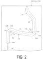
FIG. 2 is an explanatory diagram illustrating, in a plan view, a mold illustrated inFIG. 1 . -
FIG. 3 is an explanatory diagram illustrating the inside of the mold as a partially enlarged view ofFIG. 2 . -
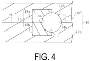
FIG. 4 is a cross-sectional view taken along a line A-A ofFIG. 3 . -
FIG. 5 is an explanatory diagram illustrating a state in which molten resin is injected into a cavity ofFIG. 3 . -
FIG. 6 is an explanatory diagram illustrating a state in which an assist material is injected into the cavity ofFIG. 5 . -
FIG. 7 is an explanatory diagram illustrating, in a plan view, the manufactured bent resin pipe according to an embodiment of the present invention. -
FIG. 8 is an explanatory diagram illustrating the inside of the bent resin pipe as a partially enlarged view ofFIG. 7 . -
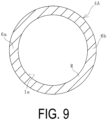
FIG. 9 is a cross-sectional view taken along a line B-B ofFIG. 8 . -
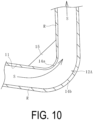
FIG. 10 is an explanatory view illustrating a state in which the assist material is injected into the cavity filled with the resin without controlling the temperature of a piece portion. -
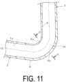
FIG. 11 is an explanatory diagram illustrating, in a plan view, the inside of a bent portion of the manufactured bent resin pipe subsequent to a step ofFIG. 10 . -
FIG. 12 is a cross-sectional view taken along a line C-C ofFIG. 11 . -
FIG. 13 is an explanatory diagram illustrating, in a plan view, a modified example of the piece portion. -
FIG. 14 is a cross-sectional view taken along a line D-D ofFIG. 13 . - A method and a device for manufacturing a bent resin pipe according to an embodiment of the present invention will be described based on an embodiment illustrated in the drawings.
- An embodiment of a
manufacturing device 7 for a bent resin pipe illustrated inFIGS. 1 to 4 includes amold 10, an injection molding machine 8 that injects molten resin R into acavity 11 of themold 10, and an assistmaterial injection unit 9 that injects an assist material S into thecavity 11. A part of themold 10 is made up of apiece portion 15 whose temperature is adjustable and includes acontrol unit 17 for controlling the temperature of thepiece portion 15. - A
bent resin pipe 1 illustrated inFIGS. 7 to 9 is manufactured using themanufacturing device 7. Thebent resin pipe 1 is a cylindrical body extending while including bent portions 4 (4A, 4B) having a smaller radius of curvature andbent portions 5 having a larger radius of curvature, and also including alinear portion 3. Both ends in the longitudinal direction of a pipe passage 1a of thebent resin pipe 1 are formed as opening portions 2. A dot-dash line CL in the drawings indicates a center line passing through the center of a transverse cross-section of the pipe passage 1a. Thebent resin pipe 1 may not include thelinear portion 3, and a number of thebent portions 4 and 5 is not limited. - As the injection molding machine 8, an injection molding machine having various known specifications for injecting the thermoplastic resin R can be used. As the resin R to be used, an appropriate type is selected according to the performance and the like required for the
bent resin pipe 1 to be manufactured. For example, when manufacturing thebent resin pipe 1 for an air conditioner to be mounted on an automobile, for example, polyamide, polyphenylene sulfide, or the like is used as the resin R. - As the assist
material injection unit 9, an assist material injection unit having various known specifications for injecting the assist material S into thecavity 11 can be used. The assist material S to be used may be a known material. An appropriate material is selected from, according to the shape and the like of thebent resin pipe 1 to be manufactured, a gas such as nitrogen gas, a liquid such as water, and a solid such as a metal ball or a resin ball. - The
cavity 11 that extends while bending is formed in themold 10. According to this embodiment, themold 10 is made up of a pair ofmolds respective molds - A runner 18a connected to the
cavity 11 via agate 18b is formed in themold 10. The runner 18a is connected to nozzles of the injection molding machine 8 and the assistmaterial injection unit 9 via sprues formed in themold 10. A discharge portion for the assist material S injected into thecavity 11 is also provided in themold 10. - The
cavity 11, which forms a hollow, extends while bending in a shape identical to that of thebent resin pipe 1 to be manufactured. At least one of a bentinner portion 14a or a bentouter portion 14b of a pre-selected bent portion 12 (12A, 12B) of thecavity 11 is made up of thepiece portion 15 whose temperature is adjustable. Specifically, themold 10 includes thepiece portion 15 incorporated into at least one of the bentinner portion 14a or the bentouter portion 14b of the pre-selected bent portion 12 (12A, 12B). - In this embodiment, only the bent
inner portion 14a is made up of thepiece portion 15. Thepiece portion 15 is made up of a pair ofpiece portions molds piece portion 15a is incorporated into the onemold 10a, and theother piece portion 15b is incorporated into theother mold 10b. - A configuration in which, of the bent
inner portion 14a and the bentouter portion 14b, only the bentouter portion 14b is made up of thepiece portion 15 can be adopted, or a configuration in which the bentinner portion 14a and the bentouter portion 14b are made up of thepiece portion 15 can be adopted. Since thebent portions bent portion 12A is illustrated in detail as representative in the drawings. - The bent portion 12 (12A, 12B) of the
cavity 11 corresponds to the bent portion 4 (4A, 4B) having the smaller radius of curvature of thebent resin pipe 1, and thebent portion 13 of thecavity 11 corresponds to thebent portion 5 having the larger radius of curvature of thebent resin pipe 1. Thus, the bent portion 12 having a relatively small radius of curvature and bend angle is selected, and at least part of the selected bent portion 12 is made up of thepiece portion 15. - A bend angle Ca of the bent
inner portion 14a of the selected bent portion 12 is, for example, 90° or less, and is more preferably 75° or less. A radius of curvature Cr of the bentinner portion 14a is, for example, 20 mm or less, and is more preferably 10 mm or less. - The
piece portion 15 constitutes, for example, an approximate range of 15 mm or more and 20 mm or less in the front-rear direction (extension direction of the cavity 11) of a bend apex P of the bentinner portion 14a. If the range (length) constituted by thepiece portion 15 is too small, the uneven thickness of thebent resin pipe 1 at the bent portion 4 cannot be corrected. On the other hand, if the range (length) constituted by thepiece portion 15 is too large, the uneven thickness is likely to occur at portions other than the bent portion 4. The range constituted by the piece portion 15 (such as the range in the extension direction of the cavity 11) is set to an appropriate value by performing a preliminary test or computer simulation. - The
piece portion 15 is preferably formed of a metal having higher thermal conductivity than a metal that forms portions of themold 10 other than thepiece portion 15. Portions of themold 10 other than thepiece portion 15 are formed of, for example, general carbon steel, and thepiece portion 15 is formed of, for example, beryllium copper alloy. - A known computer is used as the
control unit 17 for controlling the temperature of thepiece portion 15. For example, a dedicated flow path through which a medium such as water flows is formed in thepiece portion 15, and the temperature of thepiece portion 15 is controlled to a desired temperature range by adjusting the temperature of the medium as a result of a temperature controller of the medium being controlled by thecontrol unit 17. In this embodiment, water is used as the medium, and the cooling temperature of the water is adjusted by thecontrol unit 17 to cool thepiece portion 15 to the desired temperature range. - More specifically, in injecting the assist material S into the
cavity 11, thecontrol unit 17 controls the temperature of thepiece portion 15 to cause the bentinner portion 14a to have a lower temperature than the bentouter portion 14b. Causing the thermal conductivity of thepiece portion 15 to be higher than that of the other portions of themold 10 is advantageous to rapidly increase a temperature difference between thepiece portion 15 and the other portions (the bentouter portion 14b). - Next, an example of procedures of a method for manufacturing the bent resin pipe according to an embodiment of the present invention will be described.
- As illustrated in
FIGS. 1 and2 , in a state in which the pair ofmolds mold 10. The injected resin R is injected into thecavity 11, as illustrated inFIG. 5 , through the sprue, the runner 18a, and thegate 18b that are formed in themold 10. Thecavity 11 is filled with the molten resin R. - Next, the assist material S is injected at a predetermined high pressure from the assist
material injection unit 9 into themold 10. The injected assist material S passes at high pressure through the interior of thecavity 11 filled with the injected molten resin R, in the extension direction of thecavity 11. - As illustrated in
FIG. 6 , at thebent portion cavity 11, the assist material S injected at high pressure tends to pass while being unevenly distributed to an inner side of the bend, which is the shortest route in thecavity 11. As a result, under normal conditions, the resin R of the bentinner portion 14a of thebent portion inner portion 14a is thinner than the thickness of the resin R of the bentouter portion 14b, resulting in the uneven thickness. To correct the uneven thickness, in this embodiment, the temperature control of thepiece portion 15 is performed. - The assist material S passes through the
bent portion 13 in the same manner as described above. However, since the radius of curvature Cr of thebent portion 13 is relatively large, the resin R of the wall surface of the bentinner portion 14a is less likely to be scraped away by the assist material S passing at high pressure. Therefore, in thebent portion 13, the uneven thickness of the resin R is less likely to occur, and a standard thickness can be ensured. Thus, only thebent portion piece portion 15 is incorporated. - In this embodiment, in injecting the assist material S into the
cavity 11, the temperature of thepiece portion 15 is controlled by thecontrol unit 17 to cause the bentinner portion 14a of the pre-selectedbent portion outer portion 14b. All portions of thecavity 11 other than thepiece portion 15 are at substantially the same temperature, and in thecavity 11, only the bentinner portion 14a of thebent portion - By controlling the temperature of the
piece portion 15 in this manner, when the assist material S passes through, the molten resin R filled in thecavity 11 becomes harder at the bentinner portion 14a than at the bentouter portion 14b. For this reason, when the assist material S passes through thebent portion inner portion 14a as described above, the molten resin R filled in the bentinner portion 14a is not easily scraped away (is not easily removed) by the passing assist material S. - The assist material S passing through the entire length of the
cavity 11 forms the pipe passage 1a in themold 10 by the resin R remaining in thecavity 11, and the resin R being cured causes thebent resin pipe 1 having a shape corresponding to thecavity 11 to be manufactured. In this embodiment, the resin R of the bentinner portion 14a, which is disposed so as to be relatively easily scraped away by the passing assist material S, is caused to be relatively hard, thus making it less likely to be scraped away. As a result, the uneven thickness of the resin R at the bentinner portion 14a and the bentouter portion 14b of thebent portion bent resin pipe 1 illustrated inFIGS. 7 to 9 in which the uneven thickness at the bentinner portion 6a and the bentouter portion 6b of thebent portion - When the bent
inner portion 14a and the bentouter portion 14b of thebent portion piece portion 15, as illustrated inFIGS. 10 to 12 , more of the resin R is scraped away by the passing assist material S at the bentinner portion 14a than at the bentouter portion 14b. Thus, the uneven thickness occurs at thebent portion inner portion 6a. - In this embodiment, the bent
inner portion 14a of thebent portion cavity 11, the bentinner portion 14a to have a lower temperature than the bentouter portion 14b. However, the method for controlling the temperature of thecavity 11 is not limited to this embodiment. If a temperature is within a range in which the non-defectivebent resin pipe 1 can be manufactured, the bentinner portion 14a may be caused to have a lower temperature than the bentouter portion 14b in injecting the assist material S into thecavity 11 by, for example, additionally heating the bentouter portion 14b of thebent portion cavity 11 to be harder at the bentinner portion 14a than at the bentouter portion 14b. Therefore, the molten resin R filled in the bentinner portion 14a is less likely to be scraped away (less likely to be removed) by the passing assist material S. - An embodiment of the present invention can mass-produce even the
bent resin pipe 1 having a complicated shape. Using the manufacturedbent resin pipe 1 can have necessary pressure resistance while reducing weight as compared with a metal pipe. For example, thebent resin pipe 1 can also be manufactured having an inner diameter of 10 mm or more and 20 mm or less under an internal pressure of 5 MPa or more when in use. Since thebent resin pipe 1 can also be used as a low-pressure pipe, weight can significantly be reduced by replacing a general-purpose bent metal pipe with thebent resin pipe 1. - The temperature control of the
piece portion 15 preferably sets a temperature difference between the bentinner portion 14a and the bentouter portion 14b to 20°C or more and 40°C or less. If the temperature difference is less than 20°C, the difference in the hardness of the molten resin R between the bentinner portion 14a and the bentouter portion 14b cannot be made large, and it is thus difficult to obtain the effect of correcting the uneven thickness at thebent portion bent resin pipe 1. On the other hand, if the temperature difference exceeds 40°C, the fluidity of the resin R filled in the bentinner portion 14a becomes too low, or the resin R filled in the bentouter portion 14b is excessively heated to cause a problem such as burning, which increases a risk of adversely affecting the quality of the manufacturedbent resin pipe 1. - To correct the uneven thickness at the
bent portion inner portion 14a, the temperature of the bentinner portion 14a is preferably set to 30°C or more and 70°C or less and more preferably set to approximately 40°C or more and 50°C or less by the temperature control of thepiece portion 15. - The
mold 10 having specifications illustrated inFIGS. 13 and14 can also be used. In themold 10, aheat insulating layer 16 is interposed between thepiece portion 15 and the portions of themold 10 other than thepiece portion 15. Thepiece portion 15 is incorporated as a part of themold 10 with theheat insulating layer 16 interposed therebetween. - As the
heat insulating layer 16, a material is used that has a thermal conductivity lower than that of the portions of themold 10 other than thepiece portion 15. For example, when themold 10 is formed of general carbon steel (having a thermal conductivity of approximately 49.81 W/m/C), theheat insulating layer 16 is formed using a material having a thermal conductivity lower than that of the general carbon steel. For example, theheat insulating layer 16 is formed of a known ceramic (having a thermal conductivity of approximately 0.61 W/m/C). - By interposing the
heat insulating layer 16 in this manner, heat transfer between thepiece portion 15 and the portions of themold 10 other than thepiece portion 15 is blocked to some extent. This makes it advantageous to reduce an influence on thepiece portion 15 from the temperature of the peripheral portion of themold 10 to quickly bring thepiece portion 15 to a desired temperature and also makes it advantageous to stably maintain thepiece portion 15 at the desired temperature. -
- 1 Bent resin pipe
- 1a Pipe passage
- 2 Opening portion
- 3 Linear portion
- 4 (4A, 4B) Bent portion
- 5 Bent portion
- 6a Bent inner portion
- 6b Bent outer portion
- 7 Manufacturing device
- 8 Injection molding machine
- 9 Assist material injection unit
- 10 (10a, 10b) Mold
- 11 Cavity
- 12 (12A, 12B) Bent portion
- 13 Bent portion
- 14a Bent inner portion
- 14b Bent outer portion
- 15 (15a, 15b) Piece portion
- 16 Heat insulating layer
- 17 Control unit
- 18a Runner
- 18b Gate
- R Resin
- S Assist material
Claims (7)
- A method for manufacturing a bent resin pipe, the method comprising manufacturing a bent resin pipe by injecting molten resin into a cavity that extends while bending and is formed in a mold, subsequently injecting an assist material into the cavity, and curing the resin injected,
in injecting the assist material into the cavity, a bent inner portion of a pre-selected bent portion of the cavity being caused to have a lower temperature than a bent outer portion of the pre-selected bent portion. - The method for manufacturing a bent resin pipe according to claim 1, wherein a temperature difference between the bent inner portion and the bent outer portion is 20°C or more and 40°C or less.
- The method for manufacturing a bent resin pipe according to claim 1 or 2, wherein a temperature of the bent inner portion is 30°C or more and 70°C or less.
- The method for manufacturing a bent resin pipe according to any one of claims 1 to 3, wherein the bent inner portion of the pre-selected bent portion has a bend angle of 90° or less and a radius of curvature of 20 mm or less.
- A device for manufacturing a bent resin pipe, the device comprising:a mold in which a cavity that extends while bending is formed;an injection molding machine configured to inject molten resin into the cavity; andan assist material injection unit configured to inject an assist material into the cavity into which the resin is injected;at least one of a bent inner portion or a bent outer portion of a pre-selected bent portion of the cavity is made up of a piece portion whose temperature is adjustable,a control unit configured to control the temperature of the piece portion is included, andcontrolling, in injecting the assist material into the cavity, the temperature of the piece portion from the control unit causes the bent inner portion to have a lower temperature than the bent outer portion.
- The device for manufacturing a bent resin pipe according to claim 5, wherein the piece portion is formed of a metal having a higher thermal conductivity than a metal forming a portion of the mold other than the piece portion.
- The device for manufacturing a bent resin pipe according to claim 5 or 6, whereina heat insulating layer is interposed between the piece portion and the portion of the mold other than the piece portion, andthe piece portion is incorporated as a part of the mold.
Applications Claiming Priority (2)
| Application Number | Priority Date | Filing Date | Title |
|---|---|---|---|
| JP2022003815A JP7502663B2 (en) | 2022-01-13 | 2022-01-13 | Manufacturing method and device for bent resin pipe |
| PCT/JP2022/031503 WO2023135848A1 (en) | 2022-01-13 | 2022-08-22 | Production method and device for curved resin pipe |
Publications (3)
| Publication Number | Publication Date |
|---|---|
| EP4464499A1 true EP4464499A1 (en) | 2024-11-20 |
| EP4464499A4 EP4464499A4 (en) | 2025-06-25 |
| EP4464499B1 EP4464499B1 (en) | 2026-05-06 |
Family
ID=87278798
Family Applications (1)
| Application Number | Title | Priority Date | Filing Date |
|---|---|---|---|
| EP22920372.4A Active EP4464499B1 (en) | 2022-01-13 | 2022-08-22 | Production method and device for curved resin pipe |
Country Status (5)
| Country | Link |
|---|---|
| US (1) | US12617137B2 (en) |
| EP (1) | EP4464499B1 (en) |
| JP (1) | JP7502663B2 (en) |
| CN (1) | CN118284503B (en) |
| WO (1) | WO2023135848A1 (en) |
Families Citing this family (1)
| Publication number | Priority date | Publication date | Assignee | Title |
|---|---|---|---|---|
| CN121969477A (en) * | 2023-10-20 | 2026-05-01 | 横滨橡胶株式会社 | Method for manufacturing curved resin tube and curved resin tube |
Family Cites Families (24)
| Publication number | Priority date | Publication date | Assignee | Title |
|---|---|---|---|---|
| CH278661A (en) * | 1948-07-02 | 1951-10-31 | Huet Andre | Process for the manufacture of a bent tube, apparatus for carrying out this process and bent tube obtained by this process. |
| GB678002A (en) * | 1948-09-10 | 1952-08-27 | Andre Huet | Improved method of, and apparatus for, bending tubes |
| US3763293A (en) * | 1971-06-09 | 1973-10-02 | Bischoff Chemical Corp | Process of molding giant articles of structured plastic |
| US4097573A (en) * | 1972-01-12 | 1978-06-27 | Rieber & Son A/S | Method for bending thermoplastic pipes |
| JP2844942B2 (en) * | 1991-02-21 | 1999-01-13 | 豊田合成株式会社 | Method for manufacturing resin hollow molded products |
| JPH0623724U (en) * | 1992-08-27 | 1994-03-29 | 積水化学工業株式会社 | Mold for injection molding of bent tubular body |
| JPH0825397A (en) * | 1993-07-30 | 1996-01-30 | Nippon G Ii Plast Kk | Production of hollow molded product |
| JP3036335B2 (en) * | 1993-12-14 | 2000-04-24 | 日産自動車株式会社 | Hollow injection molding equipment |
| JP3194336B2 (en) * | 1994-04-29 | 2001-07-30 | 豊田合成株式会社 | Method for producing rod-shaped hollow molded article and molded article |
| EP0806272B1 (en) * | 1994-11-25 | 2002-06-05 | Asahi Kasei Kabushiki Kaisha | Improved injection molding method for producing hollow articles and mold used for said method |
| JPH08281690A (en) * | 1995-04-20 | 1996-10-29 | Sharp Corp | Hollow molding method |
| JP3113811B2 (en) * | 1995-12-28 | 2000-12-04 | 株式会社イノアックコーポレーション | Structure of synthetic resin vehicle roof rail with hollow part and method of manufacturing the same |
| JP3946813B2 (en) * | 1997-04-30 | 2007-07-18 | 日本ジーイープラスチックス株式会社 | Molding method to improve sink marks |
| JP3369962B2 (en) * | 1998-04-28 | 2003-01-20 | 東海興業株式会社 | Method and apparatus for molding resin products by gas assist molding method |
| JP2003181868A (en) | 2001-12-18 | 2003-07-02 | Toshiba Corp | Mold, gas assist molding method and apparatus |
| US7303387B2 (en) * | 2004-06-10 | 2007-12-04 | Advanced Plastics Technologies Luxembourg S.A. | System for controlling mold temperatures |
| JP5242486B2 (en) * | 2009-04-10 | 2013-07-24 | アァルピィ東プラ株式会社 | Method for producing hollow body |
| JP2012025090A (en) * | 2010-07-27 | 2012-02-09 | Nissan Motor Co Ltd | Molding method of molding section in weather strip |
| US9321195B2 (en) | 2011-07-26 | 2016-04-26 | Sanoh Industrial Co., Ltd. | Method and device for producing a pipe member |
| TW201609337A (en) * | 2014-09-03 | 2016-03-16 | 艾弗洛斯公司 | Injection molding with localized heating in flow challenge regions |
| JP6611643B2 (en) | 2016-03-05 | 2019-11-27 | ジヤトコ株式会社 | Manufacturing method of hollow tube |
| JP7131338B2 (en) | 2018-11-29 | 2022-09-06 | 横浜ゴム株式会社 | Method for manufacturing bent resin pipe |
| JP7131339B2 (en) * | 2018-11-29 | 2022-09-06 | 横浜ゴム株式会社 | Method for manufacturing bent resin pipe |
| JP7373979B2 (en) * | 2019-11-29 | 2023-11-06 | ダイキョーニシカワ株式会社 | resin pipe |
-
2022
- 2022-01-13 JP JP2022003815A patent/JP7502663B2/en active Active
- 2022-08-22 WO PCT/JP2022/031503 patent/WO2023135848A1/en not_active Ceased
- 2022-08-22 EP EP22920372.4A patent/EP4464499B1/en active Active
- 2022-08-22 CN CN202280074332.7A patent/CN118284503B/en active Active
- 2022-08-22 US US18/705,746 patent/US12617137B2/en active Active
Also Published As
| Publication number | Publication date |
|---|---|
| US12617137B2 (en) | 2026-05-05 |
| JP7502663B2 (en) | 2024-06-19 |
| CN118284503B (en) | 2025-02-28 |
| US20240326304A1 (en) | 2024-10-03 |
| CN118284503A (en) | 2024-07-02 |
| EP4464499B1 (en) | 2026-05-06 |
| WO2023135848A1 (en) | 2023-07-20 |
| JP2023103007A (en) | 2023-07-26 |
| EP4464499A4 (en) | 2025-06-25 |
Similar Documents
| Publication | Publication Date | Title |
|---|---|---|
| CN1121917C (en) | Hot chamber high-pressure metal mold casting method, mold combination and sprue insert combination | |
| US7458803B2 (en) | Composite injection molding component | |
| JP4495744B2 (en) | Nozzle connection structure of hot runner system for injection machine | |
| US12617137B2 (en) | Method and device for manufacturing bent resin pipe | |
| CN102686334A (en) | Casting method and casting device for casting | |
| DE112009001002B4 (en) | Method for reducing thermal contraction cracks during casting of super nickel alloys (SNL) | |
| EP1375107B1 (en) | Nozzle tip for hot runners injection moulds | |
| CN112893781A (en) | Core for manufacturing hollow products comprising a plurality of layers of filling material and method | |
| KR101265126B1 (en) | Apparatus and Method for Controlling Temperature of Mold | |
| CN107735194B (en) | Casting device and casting method | |
| KR20140022094A (en) | Hollow member molding apparatus and molding method | |
| JP5419394B2 (en) | Slab manufacturing method | |
| JP2010105363A (en) | Temperature controller for molding die device, and molding die system | |
| CN113613858A (en) | Injection mold, resin container production apparatus, and plug unit | |
| JP6902261B2 (en) | Injection molding mold | |
| JP2003071873A (en) | Valve gate type mold equipment | |
| KR102473584B1 (en) | Hot Runner System | |
| KR20180137834A (en) | Temperature adjusting apparatus for plastic injection mold | |
| JP4508150B2 (en) | Mold for casting and cooling method thereof | |
| JPH08267211A (en) | Method for controlling deformation of plunger sleeve for die casting | |
| CN117867263B (en) | Heat treatment method for oversized integrated die-casting die insert | |
| CN103567252B (en) | The manufacture craft of heavy wall copper pipe | |
| JP2009241327A (en) | Method for manufacturing mold and planar member for optics | |
| JP3369962B2 (en) | Method and apparatus for molding resin products by gas assist molding method | |
| CN208978215U (en) | A kind of controllable extrusion die with interior foaming layer profile wall thickness |
Legal Events
| Date | Code | Title | Description |
|---|---|---|---|
| STAA | Information on the status of an ep patent application or granted ep patent |
Free format text: STATUS: THE INTERNATIONAL PUBLICATION HAS BEEN MADE |
|
| PUAI | Public reference made under article 153(3) epc to a published international application that has entered the european phase |
Free format text: ORIGINAL CODE: 0009012 |
|
| STAA | Information on the status of an ep patent application or granted ep patent |
Free format text: STATUS: REQUEST FOR EXAMINATION WAS MADE |
|
| 17P | Request for examination filed |
Effective date: 20240704 |
|
| AK | Designated contracting states |
Kind code of ref document: A1 Designated state(s): AL AT BE BG CH CY CZ DE DK EE ES FI FR GB GR HR HU IE IS IT LI LT LU LV MC MK MT NL NO PL PT RO RS SE SI SK SM TR |
|
| DAV | Request for validation of the european patent (deleted) | ||
| DAX | Request for extension of the european patent (deleted) | ||
| A4 | Supplementary search report drawn up and despatched |
Effective date: 20250523 |
|
| RIC1 | Information provided on ipc code assigned before grant |
Ipc: B29L 23/00 20060101ALN20250519BHEP Ipc: B29C 45/26 20060101ALI20250519BHEP Ipc: B29C 45/17 20060101ALI20250519BHEP Ipc: F16L 9/127 20060101ALI20250519BHEP Ipc: B29D 23/00 20060101ALI20250519BHEP Ipc: B29C 45/78 20060101ALI20250519BHEP Ipc: B29C 45/37 20060101ALI20250519BHEP Ipc: B29C 45/73 20060101AFI20250519BHEP |
|
| GRAP | Despatch of communication of intention to grant a patent |
Free format text: ORIGINAL CODE: EPIDOSNIGR1 |
|
| STAA | Information on the status of an ep patent application or granted ep patent |
Free format text: STATUS: GRANT OF PATENT IS INTENDED |
|
| RIC1 | Information provided on ipc code assigned before grant |
Ipc: B29C 45/73 20060101AFI20260202BHEP Ipc: B29C 45/37 20060101ALI20260202BHEP Ipc: B29C 45/78 20060101ALI20260202BHEP Ipc: B29D 23/00 20060101ALI20260202BHEP Ipc: F16L 9/127 20060101ALI20260202BHEP Ipc: B29C 45/17 20060101ALI20260202BHEP Ipc: B29C 45/26 20060101ALI20260202BHEP Ipc: B29L 23/00 20060101ALN20260202BHEP |
|
| INTG | Intention to grant announced |
Effective date: 20260220 |
|
| GRAS | Grant fee paid |
Free format text: ORIGINAL CODE: EPIDOSNIGR3 |
|
| GRAA | (expected) grant |
Free format text: ORIGINAL CODE: 0009210 |
|
| STAA | Information on the status of an ep patent application or granted ep patent |
Free format text: STATUS: THE PATENT HAS BEEN GRANTED |
|
| P01 | Opt-out of the competence of the unified patent court (upc) registered |
Free format text: CASE NUMBER: UPC_APP_0010308_4464499/2026 Effective date: 20260318 |
|
| AK | Designated contracting states |
Kind code of ref document: B1 Designated state(s): AL AT BE BG CH CY CZ DE DK EE ES FI FR GB GR HR HU IE IS IT LI LT LU LV MC MK MT NL NO PL PT RO RS SE SI SK SM TR |
|
| REG | Reference to a national code |
Ref country code: CH Ref legal event code: F10 Free format text: ST27 STATUS EVENT CODE: U-0-0-F10-F00 (AS PROVIDED BY THE NATIONAL OFFICE) Effective date: 20260506 Ref country code: GB Ref legal event code: FG4D |