EP4464452A1 - Sputter measurement system - Google Patents
Sputter measurement system Download PDFInfo
- Publication number
- EP4464452A1 EP4464452A1 EP24166430.9A EP24166430A EP4464452A1 EP 4464452 A1 EP4464452 A1 EP 4464452A1 EP 24166430 A EP24166430 A EP 24166430A EP 4464452 A1 EP4464452 A1 EP 4464452A1
- Authority
- EP
- European Patent Office
- Prior art keywords
- sputter
- camera
- spot light
- molten portion
- measurement system
- Prior art date
- Legal status (The legal status is an assumption and is not a legal conclusion. Google has not performed a legal analysis and makes no representation as to the accuracy of the status listed.)
- Granted
Links
Images


Classifications
-
- B—PERFORMING OPERATIONS; TRANSPORTING
- B23—MACHINE TOOLS; METAL-WORKING NOT OTHERWISE PROVIDED FOR
- B23K—SOLDERING OR UNSOLDERING; WELDING; CLADDING OR PLATING BY SOLDERING OR WELDING; CUTTING BY APPLYING HEAT LOCALLY, e.g. FLAME CUTTING; WORKING BY LASER BEAM
- B23K26/00—Working by laser beam, e.g. welding, cutting or boring
- B23K26/02—Positioning or observing the workpiece, e.g. with respect to the point of impact; Aligning, aiming or focusing the laser beam
- B23K26/03—Observing, e.g. monitoring, the workpiece
- B23K26/032—Observing, e.g. monitoring, the workpiece using optical means
-
- B—PERFORMING OPERATIONS; TRANSPORTING
- B23—MACHINE TOOLS; METAL-WORKING NOT OTHERWISE PROVIDED FOR
- B23K—SOLDERING OR UNSOLDERING; WELDING; CLADDING OR PLATING BY SOLDERING OR WELDING; CUTTING BY APPLYING HEAT LOCALLY, e.g. FLAME CUTTING; WORKING BY LASER BEAM
- B23K9/00—Arc welding or cutting
- B23K9/095—Monitoring or automatic control of welding parameters
- B23K9/0956—Monitoring or automatic control of welding parameters using sensing means, e.g. optical
-
- B—PERFORMING OPERATIONS; TRANSPORTING
- B23—MACHINE TOOLS; METAL-WORKING NOT OTHERWISE PROVIDED FOR
- B23K—SOLDERING OR UNSOLDERING; WELDING; CLADDING OR PLATING BY SOLDERING OR WELDING; CUTTING BY APPLYING HEAT LOCALLY, e.g. FLAME CUTTING; WORKING BY LASER BEAM
- B23K37/00—Auxiliary devices or processes, not specially adapted for a procedure covered by only one of the other main groups of this subclass
-
- B—PERFORMING OPERATIONS; TRANSPORTING
- B23—MACHINE TOOLS; METAL-WORKING NOT OTHERWISE PROVIDED FOR
- B23K—SOLDERING OR UNSOLDERING; WELDING; CLADDING OR PLATING BY SOLDERING OR WELDING; CUTTING BY APPLYING HEAT LOCALLY, e.g. FLAME CUTTING; WORKING BY LASER BEAM
- B23K31/00—Processes relevant to this subclass, specially adapted for particular articles or purposes, but not covered by any single one of main groups B23K1/00 - B23K28/00
- B23K31/12—Processes relevant to this subclass, specially adapted for particular articles or purposes, but not covered by any single one of main groups B23K1/00 - B23K28/00 relating to investigating the properties, e.g. the weldability, of materials
- B23K31/125—Weld quality monitoring
-
- B—PERFORMING OPERATIONS; TRANSPORTING
- B23—MACHINE TOOLS; METAL-WORKING NOT OTHERWISE PROVIDED FOR
- B23K—SOLDERING OR UNSOLDERING; WELDING; CLADDING OR PLATING BY SOLDERING OR WELDING; CUTTING BY APPLYING HEAT LOCALLY, e.g. FLAME CUTTING; WORKING BY LASER BEAM
- B23K9/00—Arc welding or cutting
- B23K9/095—Monitoring or automatic control of welding parameters
- B23K9/0953—Monitoring or automatic control of welding parameters using computing means
-
- G—PHYSICS
- G01—MEASURING; TESTING
- G01N—INVESTIGATING OR ANALYSING MATERIALS BY DETERMINING THEIR CHEMICAL OR PHYSICAL PROPERTIES
- G01N15/00—Investigating characteristics of particles; Investigating permeability, pore-volume or surface-area of porous materials
- G01N15/02—Investigating particle size or size distribution
- G01N15/0205—Investigating particle size or size distribution by optical means
-
- G—PHYSICS
- G01—MEASURING; TESTING
- G01N—INVESTIGATING OR ANALYSING MATERIALS BY DETERMINING THEIR CHEMICAL OR PHYSICAL PROPERTIES
- G01N21/00—Investigating or analysing materials by the use of optical means, i.e. using sub-millimetre waves, infrared, visible or ultraviolet light
- G01N21/84—Systems specially adapted for particular applications
- G01N21/88—Investigating the presence of flaws or contamination
- G01N21/8806—Specially adapted optical and illumination features
-
- G—PHYSICS
- G01—MEASURING; TESTING
- G01N—INVESTIGATING OR ANALYSING MATERIALS BY DETERMINING THEIR CHEMICAL OR PHYSICAL PROPERTIES
- G01N21/00—Investigating or analysing materials by the use of optical means, i.e. using sub-millimetre waves, infrared, visible or ultraviolet light
- G01N21/84—Systems specially adapted for particular applications
- G01N21/88—Investigating the presence of flaws or contamination
- G01N21/8851—Scan or image signal processing specially adapted therefor, e.g. for scan signal adjustment, for detecting different kinds of defects, for compensating for structures, markings, edges
-
- G—PHYSICS
- G02—OPTICS
- G02B—OPTICAL ELEMENTS, SYSTEMS OR APPARATUS
- G02B13/00—Optical objectives specially designed for the purposes specified below
- G02B13/22—Telecentric objectives or lens systems
-
- G—PHYSICS
- G01—MEASURING; TESTING
- G01N—INVESTIGATING OR ANALYSING MATERIALS BY DETERMINING THEIR CHEMICAL OR PHYSICAL PROPERTIES
- G01N21/00—Investigating or analysing materials by the use of optical means, i.e. using sub-millimetre waves, infrared, visible or ultraviolet light
- G01N21/84—Systems specially adapted for particular applications
- G01N21/88—Investigating the presence of flaws or contamination
- G01N21/8851—Scan or image signal processing specially adapted therefor, e.g. for scan signal adjustment, for detecting different kinds of defects, for compensating for structures, markings, edges
- G01N2021/8854—Grading and classifying of flaws
- G01N2021/8874—Taking dimensions of defect into account
Definitions
- the present disclosure relates to a technology for measuring a sputter generated during welding.
- a molten metal particle in the form of a droplet flies from a surface of a molten portion that is melted during the welding. Since the sputter may decrease quality of the product after the welding, it is desirable to suppress generation of the sputter. For this purpose, first, it is desired to measure generation of the sputter.
- Japanese Patent Laying-Open No. 2019-188421 discloses an apparatus that can measure the number of sputters by performing image processing on data obtained by capturing an image of a welded portion using a camera during welding.
- the sputters flying from the molten portion include not only a sputter involving a large amount of emission of light but also a sputter involving a small amount of emission of light. Therefore, when the sputters are simply captured in image by the camera, an image of the sputter involving a small amount of emission of light among the sputters flying from the molten portion cannot be captured, with the result that the sputter and the size of the sputter may be unable to be measured.
- the present disclosure has been made to solve the above-described problem, and has an object to precisely measure a size of a sputter even when an amount of emission of light by the sputter is small.
- a sputter measurement system is a sputter measurement system that measures a size of a sputter flying from a molten portion that is melted during welding, the sputter measurement system including: a camera that captures an image of an observation region including the molten portion; a spot light source that applies spot light toward the observation region from a lateral side with respect to the observation region when viewed from the camera; and a controller that measures the size of the sputter based on the image captured by the camera.
- the sputter measurement system according to item 1 further includes a telecentric lens disposed between the molten portion and the camera.
- a position of the molten portion is included in a depth-of-field range of the telecentric lens, the sputter measurement system further including a member disposed between the molten portion and the spot light source, the member being provided with a slit for matching an application range of the spot light with the depth-of-field range of the telecentric lens.
- Fig. 1 is a diagram schematically showing an exemplary overall configuration of a sputter measurement system 1 according to the present embodiment.
- Base members 2, 3 each composed of a metal are welded by laser light 5 emitted from a laser generation apparatus (not shown) for the sake of processing.
- a portion to which laser light 5 is applied during the welding is melted to become a molten portion 6.
- a welding proceeding direction Y direction in the figure
- a welding bead extending in the Y direction in the figure is formed.
- the Y direction represents the above-described welding proceeding direction
- the Z direction represents a normal direction of each of base members 2, 3
- the X direction represents a direction orthogonal to the Y direction and the Z direction.
- sputters 7 may fly from molten portion 6. Each of sputters 7 may decrease quality of the product after the welding. For example, in the case where the welding is performed to connect between a cell terminal of a power storage battery and a bus bar, flying of sputter 7 can be a factor of short-circuiting or disconnecting a wiring therearound due to sputter 7 breaking a resin coating material that covers the wiring, or can be a factor of short-circuiting a circuit of a substrate therearound due to sputter 7 being adhered between welding pins of the substrate. Therefore, it is desirable to suppress generation of sputter 7 itself or to ensure that no problem is caused even when sputter 7 is generated. For this purpose, first, it is desired to measure generation of the sputter.
- sputter measurement system 1 is configured to measure the size (dimension) of sputter 7 flying from molten portion 6.
- sputter measurement system 1 includes spot light sources 10R, 10L, a camera 30, a telecentric lens 40, and a controller 100.
- Camera 30 captures, at a high speed, an image of an observation region including molten portion 6 that is melted by laser light 5. Camera 30 outputs, to controller 100, image data obtained by the image capturing. It should be noted that a blackout curtain 4 that does not reflect light is disposed on the rear side with respect to the observation region when viewed from camera 30.
- Telecentric lens 40 is disposed in an optical path between molten portion 6 and camera 30.
- Telecentric lens 40 is a special lens that can produce light having a main optical axis parallel to the optical axis of the lens, unlike an ordinary lens. Due to its optical characteristic, telecentric lens 40 has a region (hereinafter also referred to as "depth-of-field region R1") in which the size of the image of the target is not changed even when a distance between camera 30 and the target is changed.
- the size of the image of sputter 7 is not changed regardless of the position of sputter 7 (even when the position of sputter 7 is deviated from the focal position due to flying) as long as sputter 7 is included in depth-of-field region R1 of telecentric lens 40, and distortion of the image due to parallax is not caused.
- the sputters flying from molten portion 6 include not only a sputter involving a large amount of emission of light but also a sputter involving a small amount of emission of light. Therefore, when sputters 7 are simply captured in image by camera 30, an image of the sputter involving a small amount of emission of light among sputters 7 flying from molten portion 6 cannot be captured, with the result that the sputter and the size of the sputter may be unable to be measured.
- spot light sources 10R, 10L include spot light sources 10R, 10L.
- Each of spot light sources 10R, 10L emits spot light that spreads in the form of a cone as irradiation light for observation of each of the sputters.
- Spot light sources 10R, 10L are disposed at positions facing each other with molten portion 6 being interposed therebetween.
- spot light source 10R emits spot light toward the right side of the observation region including molten portion 6 when viewed from camera 30.
- spot light source 10R includes: a light source 11R that generates light having a high luminance in accordance with a command from controller 100; and a light source lens 12R that converts the light generated by light source 11R into spot light and that emits the spot light toward molten portion 6.
- the optical axis of light source lens 12R is orthogonal to the optical axis of camera 30.
- spot light source 10L emits spot light toward the left side of the observation region including molten portion 6 when viewed from camera 30.
- spot light source 10L includes: a light source 11L that generates light having a high luminance in accordance with a command from controller 100; and a light source lens 12L that converts the light generated by light source 11L into spot light and that emits the spot light toward molten portion 6.
- the optical axis of light source lens 12L is orthogonal to the optical axis of camera 30.
- Controller 100 includes a CPU (Central Processing Unit), and a memory such as a ROM (Read Only Memory) and a RAM (Random Access Memory). During the welding of base members 2, 3, controller 100 measures the size of sputter 7 flying from molten portion 6 based on image data captured by camera 30 with spot light sources 10R, 10L being each operated to laterally apply the spot light to the observation region including molten portion 6.
- CPU Central Processing Unit
- ROM Read Only Memory
- RAM Random Access Memory
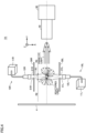
- Fig. 2 is a diagram schematically showing a principle of measuring sputter 7 by sputter measurement system 1.
- Sputter 7 is measured in an in-process manner during the welding of base members 2, 3.
- the observation region captured in image by camera 30 includes: a depth-of-field region R1 of telecentric lens 40; a remote region R2 far away from camera 30 with respect to depth-of-field region R1; and a close region R3 close to camera 30 with respect to depth-of-field region R1. It should be noted that depth-of-field region R1 is in a range of several mm from the focal position.
- a relative position between molten portion 6 and telecentric lens 40 in the Y direction is adjusted such that molten portion 6 is included in depth-of-field region R1 of telecentric lens 40. Further, a relative position between molten portion 6 and each of light source lenses 12R, 12L in the Y direction is adjusted to apply spot light 21R and spot light 21L to the observation region including molten portion 6. Further, in the present embodiment, a relative position between molten portion 6 and each of light source lenses 12R, 12L in the X direction or an application angle (spreading) of each of spot light 21R and spot light 21L is adjusted to substantially match the application range of each of spot light 21R and spot light 21L with depth-of-field region R1.
- spot light 21R and spot light 21L are applied onto the left and right sides of sputter 7.
- diffused light scattered light
- parallel light passing through telecentric lens 40 in the diffused light is captured in image by camera 30. Therefore, the shape of sputter 7 on each of the left and right sides is captured in image as a bright spot.
- spot light 21R and spot light 21L onto the respective lateral sides of sputter 7 that is the measurement target, the shape of sputter 7 on each of the left and right sides is captured in image by camera 30.
- Controller 100 measures the size of sputter 7 in accordance with the shape of sputter 7 on each of the respective lateral sides as captured in image by camera 30. As a result, even when the amount of emission of light by sputter 7 is small, sputter 7 and the size of sputter 7 can be precisely measured.
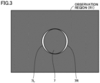
- Fig. 3 is a diagram showing an exemplary image of the observation region captured by camera 30.
- Bright spot portions 7R, 7L included in the image of the observation region are images of shapes of edges, on the right and left sides, of sputter 7 existing in depth-of-field region R1.
- Controller 100 estimates an entire shape of sputter 7 in accordance with the shapes of bright spot portions 7R, 7L, and measures the size (dimension) of sputter 7 in accordance with the estimated entire shape.
- the measured size of the sputter is substantially unchanged regardless of whether the sputter is far from or close to the camera. Therefore, even when sputter 7 is moved due to flying, the size (dimension) of sputter 7 can be precisely measured as long as sputter 7 exists in depth-of-field region R1.
- the application range of each of spot light 21R and spot light 21L is adjusted to be substantially matched with depth-of-field region R1. Therefore, the sputter in each of remote region R2 and close region R3 is not irradiated with spot light 21R and spot light 21L, with the result that the sputter is not captured in the image of the observation region.
- sputter 7 existing in each of remote region R2 and close region R3 in each of which the size of the image is changed depending on whether or not sputter 7 is far from or close to the camera is excluded from the dimension measurement target. Therefore, precision in the measurement of sputter 7 is suppressed from being decreased.
- spot light 21R and spot light 21L are applied onto the lateral sides of sputter 7 to generate the diffused light (scattered light) on each of the lateral sides of sputter 7, the shape of sputter 7 on each of the lateral sides is measured by capturing the diffused light in image by camera 30, and the size of the sputter is measured in accordance with the measured shape of the sputter on each of the lateral sides.
- the size of sputter 7 can be measured even when the amount of emission of light by sputter 7 is small.
- telecentric lens 40 is disposed between molten portion 6 and camera 30. Therefore, the size of the sputter can be precisely measured regardless of whether the sputter is far from or close to the camera.
- the application range of each of spot light 21R and spot light 21L is matched with depth-of-field region R1 by adjusting the relative position between molten portion 6 and each of light source lenses 12R, 12L in the X direction or by adjusting the application angle of each of spot light 21R and spot light 21L.
- the method of matching the application range of each of spot light 21R and spot light 21L with depth-of-field region R1 is not limited to such a method.
- Fig. 4 is a diagram schematically showing a principle of measuring a sputter 7 by a sputter measurement system 1A according to a modification 1.
- Sputter measurement system 1A is obtained by adding slit plates 50R, 50L to sputter measurement system 1 shown in Fig. 1 .
- Slit plate 50R is disposed between molten portion 6 and light source lens 12R, and is provided with a slit 51R for matching the application range of spot light 21R with depth-of-field region R1 of telecentric lens 40.
- Slit plate 50L is disposed between molten portion 6 and light source lens 12L, and is provided with a slit 51L for matching the application range of spot light 21L with depth-of-field region R1 of telecentric lens 40.
- the application range of each of spot light 21R and spot light 21L may be matched with depth-of-field region R1.
- the left and right sides of the sputter are irradiated by two spot light sources 10R, 10L on the left and right in the above-described embodiment, either one of the left and right sides of the sputter may be irradiated by one spot light source. Also in this way, the shape of the sputter on one of the left and right sides can be measured, the entire shape of sputter 7 can be estimated in accordance with the measured shape on the side, and the size of sputter 7 can be measured in accordance with the estimated entire shape.
Landscapes
- Engineering & Computer Science (AREA)
- Physics & Mathematics (AREA)
- Mechanical Engineering (AREA)
- General Physics & Mathematics (AREA)
- Chemical & Material Sciences (AREA)
- Optics & Photonics (AREA)
- Health & Medical Sciences (AREA)
- Life Sciences & Earth Sciences (AREA)
- Analytical Chemistry (AREA)
- Biochemistry (AREA)
- General Health & Medical Sciences (AREA)
- Immunology (AREA)
- Pathology (AREA)
- Plasma & Fusion (AREA)
- Quality & Reliability (AREA)
- Dispersion Chemistry (AREA)
- Theoretical Computer Science (AREA)
- Computer Vision & Pattern Recognition (AREA)
- Signal Processing (AREA)
- Length Measuring Devices By Optical Means (AREA)
Abstract
Description
- This nonprovisional application is based on
Japanese Patent Application No. 2023-080762 filed on May 16, 2023 - The present disclosure relates to a technology for measuring a sputter generated during welding.
- When welding a metal, there may occur a phenomenon in which a molten metal particle (sputter) in the form of a droplet flies from a surface of a molten portion that is melted during the welding. Since the sputter may decrease quality of the product after the welding, it is desirable to suppress generation of the sputter. For this purpose, first, it is desired to measure generation of the sputter.
- As an exemplary apparatus for measuring generation of the sputter, for example,
Japanese Patent Laying-Open No. 2019-188421 - The sputters flying from the molten portion include not only a sputter involving a large amount of emission of light but also a sputter involving a small amount of emission of light. Therefore, when the sputters are simply captured in image by the camera, an image of the sputter involving a small amount of emission of light among the sputters flying from the molten portion cannot be captured, with the result that the sputter and the size of the sputter may be unable to be measured.
- The present disclosure has been made to solve the above-described problem, and has an object to precisely measure a size of a sputter even when an amount of emission of light by the sputter is small.
- (Item 1) A sputter measurement system according to the present disclosure is a sputter measurement system that measures a size of a sputter flying from a molten portion that is melted during welding, the sputter measurement system including: a camera that captures an image of an observation region including the molten portion; a spot light source that applies spot light toward the observation region from a lateral side with respect to the observation region when viewed from the camera; and a controller that measures the size of the sputter based on the image captured by the camera.
- (Item 2) The sputter measurement system according to
item 1 further includes a telecentric lens disposed between the molten portion and the camera. - (Item 3) In the sputter measurement system according to
item 2, a position of the molten portion is included in a depth-of-field range of the telecentric lens, the sputter measurement system further including a member disposed between the molten portion and the spot light source, the member being provided with a slit for matching an application range of the spot light with the depth-of-field range of the telecentric lens. - The foregoing and other objects, features, aspects and advantages of the present invention will become more apparent from the following detailed description of the present invention when taken in conjunction with the accompanying drawings.
-
-
Fig. 1 is a diagram schematically showing an exemplary overall configuration of a sputter measurement system. -
Fig. 2 is a first diagram schematically showing a principle of measuring a sputter. -
Fig. 3 is a diagram showing an exemplary image of an observation region captured by a camera. -
Fig. 4 is a second diagram schematically showing a principle of measuring a sputter. -
Fig. 1 is a diagram schematically showing an exemplary overall configuration of asputter measurement system 1 according to the present embodiment.Base members laser light 5 emitted from a laser generation apparatus (not shown) for the sake of processing. A portion to whichlaser light 5 is applied during the welding is melted to become amolten portion 6. By moving the laser generation apparatus in a welding proceeding direction (Y direction in the figure), a welding bead extending in the Y direction in the figure is formed. It should be noted that in the figure, the Y direction represents the above-described welding proceeding direction, the Z direction represents a normal direction of each ofbase members - During the welding of
base members sputters 7 may fly frommolten portion 6. Each ofsputters 7 may decrease quality of the product after the welding. For example, in the case where the welding is performed to connect between a cell terminal of a power storage battery and a bus bar, flying ofsputter 7 can be a factor of short-circuiting or disconnecting a wiring therearound due tosputter 7 breaking a resin coating material that covers the wiring, or can be a factor of short-circuiting a circuit of a substrate therearound due tosputter 7 being adhered between welding pins of the substrate. Therefore, it is desirable to suppress generation ofsputter 7 itself or to ensure that no problem is caused even whensputter 7 is generated. For this purpose, first, it is desired to measure generation of the sputter. - In view of such a point,
sputter measurement system 1 according to the present embodiment is configured to measure the size (dimension) ofsputter 7 flying frommolten portion 6. Specifically,sputter measurement system 1 includesspot light sources camera 30, atelecentric lens 40, and acontroller 100. -
Camera 30 captures, at a high speed, an image of an observation region includingmolten portion 6 that is melted bylaser light 5.Camera 30 outputs, to controller 100, image data obtained by the image capturing. It should be noted that ablackout curtain 4 that does not reflect light is disposed on the rear side with respect to the observation region when viewed fromcamera 30. -
Telecentric lens 40 is disposed in an optical path betweenmolten portion 6 andcamera 30.Telecentric lens 40 is a special lens that can produce light having a main optical axis parallel to the optical axis of the lens, unlike an ordinary lens. Due to its optical characteristic,telecentric lens 40 has a region (hereinafter also referred to as "depth-of-field region R1") in which the size of the image of the target is not changed even when a distance betweencamera 30 and the target is changed. Therefore, by capturing the image of the target, i.e.,sputter 7 usingcamera 30 withtelecentric lens 40 being interposed therebetween, the size of the image ofsputter 7 is not changed regardless of the position of sputter 7 (even when the position ofsputter 7 is deviated from the focal position due to flying) as long assputter 7 is included in depth-of-field region R1 oftelecentric lens 40, and distortion of the image due to parallax is not caused. - The sputters flying from
molten portion 6 include not only a sputter involving a large amount of emission of light but also a sputter involving a small amount of emission of light. Therefore, whensputters 7 are simply captured in image bycamera 30, an image of the sputter involving a small amount of emission of light amongsputters 7 flying frommolten portion 6 cannot be captured, with the result that the sputter and the size of the sputter may be unable to be measured. - In view of such a point,
sputter measurement system 1 according to the present embodiment includesspot light sources spot light sources Spot light sources molten portion 6 being interposed therebetween. -
Spot light source 10R emits spot light toward the right side of the observation region includingmolten portion 6 when viewed fromcamera 30. Specifically,spot light source 10R includes: alight source 11R that generates light having a high luminance in accordance with a command fromcontroller 100; and alight source lens 12R that converts the light generated bylight source 11R into spot light and that emits the spot light towardmolten portion 6. The optical axis oflight source lens 12R is orthogonal to the optical axis ofcamera 30. -
Spot light source 10L emits spot light toward the left side of the observation region includingmolten portion 6 when viewed fromcamera 30. Specifically,spot light source 10L includes: alight source 11L that generates light having a high luminance in accordance with a command fromcontroller 100; and alight source lens 12L that converts the light generated bylight source 11L into spot light and that emits the spot light towardmolten portion 6. The optical axis oflight source lens 12L is orthogonal to the optical axis ofcamera 30. -
Controller 100 includes a CPU (Central Processing Unit), and a memory such as a ROM (Read Only Memory) and a RAM (Random Access Memory). During the welding ofbase members controller 100 measures the size ofsputter 7 flying frommolten portion 6 based on image data captured bycamera 30 withspot light sources molten portion 6. -
Fig. 2 is a diagram schematically showing a principle of measuringsputter 7 bysputter measurement system 1.Sputter 7 is measured in an in-process manner during the welding ofbase members - The observation region captured in image by
camera 30 includes: a depth-of-field region R1 oftelecentric lens 40; a remote region R2 far away fromcamera 30 with respect to depth-of-field region R1; and a close region R3 close tocamera 30 with respect to depth-of-field region R1. It should be noted that depth-of-field region R1 is in a range of several mm from the focal position. - During the measurement of
sputter 7, a relative position betweenmolten portion 6 andtelecentric lens 40 in the Y direction is adjusted such thatmolten portion 6 is included in depth-of-field region R1 oftelecentric lens 40. Further, a relative position betweenmolten portion 6 and each oflight source lenses spot light 21R andspot light 21L to the observation region includingmolten portion 6. Further, in the present embodiment, a relative position betweenmolten portion 6 and each oflight source lenses spot light 21R andspot light 21L is adjusted to substantially match the application range of each ofspot light 21R andspot light 21L with depth-of-field region R1. - When
sputter 7 does not exist in the observation region, the target to which each ofspot light 21R andspot light 21L is applied does not exist in the observation region, and onlyblackout curtain 4 is captured in image bycamera 30, with the result that the entire image of the observation region becomes a dark spot. - On the other hand, when
sputter 7 exists in depth-of-field region R1 oftelecentric lens 40,spot light 21R andspot light 21L are applied onto the left and right sides ofsputter 7. Thus, diffused light (scattered light) is generated on each of the left and right sides ofsputter 7, and parallel light passing throughtelecentric lens 40 in the diffused light is captured in image bycamera 30. Therefore, the shape ofsputter 7 on each of the left and right sides is captured in image as a bright spot. In other words, in the present embodiment, by applyingspot light 21R and spot light 21L onto the respective lateral sides ofsputter 7 that is the measurement target, the shape ofsputter 7 on each of the left and right sides is captured in image bycamera 30.Controller 100 measures the size ofsputter 7 in accordance with the shape ofsputter 7 on each of the respective lateral sides as captured in image bycamera 30. As a result, even when the amount of emission of light bysputter 7 is small,sputter 7 and the size ofsputter 7 can be precisely measured. -
Fig. 3 is a diagram showing an exemplary image of the observation region captured bycamera 30.Bright spot portions sputter 7 existing in depth-of-field region R1.Controller 100 estimates an entire shape ofsputter 7 in accordance with the shapes ofbright spot portions sputter 7 in accordance with the estimated entire shape. - When
sputter 7 exists in depth-of-field region R1 oftelecentric lens 40, the measured size of the sputter is substantially unchanged regardless of whether the sputter is far from or close to the camera. Therefore, even whensputter 7 is moved due to flying, the size (dimension) ofsputter 7 can be precisely measured as long assputter 7 exists in depth-of-field region R1. - Returning to
Fig. 2 , when the sputter exists in remote region R2 or close region R3, the size of the image of the sputter is changed depending on whether the sputter is far from or close to camera 30 (distance to camera 30), with the result that it becomes difficult to precisely measure the size of the sputter. - In view of this point, in the present embodiment, as described above, the application range of each of
spot light 21R and spot light 21L is adjusted to be substantially matched with depth-of-field region R1. Therefore, the sputter in each of remote region R2 and close region R3 is not irradiated withspot light 21R and spot light 21L, with the result that the sputter is not captured in the image of the observation region. Thus, sputter 7 existing in each of remote region R2 and close region R3 in each of which the size of the image is changed depending on whether or not sputter 7 is far from or close to the camera is excluded from the dimension measurement target. Therefore, precision in the measurement ofsputter 7 is suppressed from being decreased. - As described above, in
sputter measurement system 1 according to the present embodiment, spot light 21R and spot light 21L are applied onto the lateral sides ofsputter 7 to generate the diffused light (scattered light) on each of the lateral sides ofsputter 7, the shape ofsputter 7 on each of the lateral sides is measured by capturing the diffused light in image bycamera 30, and the size of the sputter is measured in accordance with the measured shape of the sputter on each of the lateral sides. As a result, the size ofsputter 7 can be measured even when the amount of emission of light bysputter 7 is small. - Further, in
sputter measurement system 1 according to the present embodiment,telecentric lens 40 is disposed betweenmolten portion 6 andcamera 30. Therefore, the size of the sputter can be precisely measured regardless of whether the sputter is far from or close to the camera. - In the above-described embodiment, the application range of each of
spot light 21R and spot light 21L is matched with depth-of-field region R1 by adjusting the relative position betweenmolten portion 6 and each oflight source lenses spot light 21R and spot light 21L. However, the method of matching the application range of each ofspot light 21R and spot light 21L with depth-of-field region R1 is not limited to such a method. -
Fig. 4 is a diagram schematically showing a principle of measuring asputter 7 by asputter measurement system 1A according to amodification 1.Sputter measurement system 1A is obtained by addingslit plates measurement system 1 shown inFig. 1 . -
Slit plate 50R is disposed betweenmolten portion 6 andlight source lens 12R, and is provided with aslit 51R for matching the application range ofspot light 21R with depth-of-field region R1 oftelecentric lens 40. -
Slit plate 50L is disposed betweenmolten portion 6 andlight source lens 12L, and is provided with aslit 51L for matching the application range ofspot light 21L with depth-of-field region R1 oftelecentric lens 40. - Thus, by disposing
slit plate 50R betweenmolten portion 6 andlight source lens 12R and disposingslit plate 50L betweenmolten portion 6 andlight source lens 12L, the application range of each ofspot light 21R and spot light 21L may be matched with depth-of-field region R1. - Although the left and right sides of the sputter are irradiated by two
spot light sources sputter 7 can be estimated in accordance with the measured shape on the side, and the size ofsputter 7 can be measured in accordance with the estimated entire shape. - Although the embodiments of the present invention have been described and illustrated in detail, it is clearly understood that the same is by way of illustration and example only and is not to be taken by way of limitation. The scope of the present invention is defined by the terms of the claims, and is intended to include any modifications within the scope and meaning equivalent to the terms of the claims.
Claims (3)
- A sputter measurement system that measures a size of a sputter (7) flying from a molten portion (6) that is melted during welding, the sputter measurement system comprising:a camera (30) that captures an image of an observation region including the molten portion (6);a spot light source (10R, 10L) that applies spot light (21R, 21L) toward the observation region from a lateral side with respect to the observation region when viewed from the camera (30); anda controller (100) that measures the size of the sputter (7) based on the image captured by the camera (30).
- The sputter measurement system according to claim 1, further comprising a telecentric lens (40) disposed between the molten portion (6) and the camera (30).
- The sputter measurement system according to claim 2, wherein a position of the molten portion (6) is included in a depth-of-field range of the telecentric lens (40),
the sputter measurement system further comprising a member (50R, 50L) disposed between the molten portion (6) and the spot light source (10R, 10L), the member (50R, 50L) being provided with a slit (51R, 51L) for matching an application range of the spot light (21R, 21L) with the depth-of-field range of the telecentric lens (40).
Applications Claiming Priority (1)
| Application Number | Priority Date | Filing Date | Title |
|---|---|---|---|
| JP2023080762A JP7659586B2 (en) | 2023-05-16 | 2023-05-16 | Sputter Measurement System |
Publications (2)
| Publication Number | Publication Date |
|---|---|
| EP4464452A1 true EP4464452A1 (en) | 2024-11-20 |
| EP4464452B1 EP4464452B1 (en) | 2025-06-18 |
Family
ID=90482095
Family Applications (1)
| Application Number | Title | Priority Date | Filing Date |
|---|---|---|---|
| EP24166430.9A Active EP4464452B1 (en) | 2023-05-16 | 2024-03-26 | Sputter measurement system |
Country Status (5)
| Country | Link |
|---|---|
| US (1) | US20240383077A1 (en) |
| EP (1) | EP4464452B1 (en) |
| JP (1) | JP7659586B2 (en) |
| KR (1) | KR20240165870A (en) |
| CN (1) | CN118989725A (en) |
Citations (3)
| Publication number | Priority date | Publication date | Assignee | Title |
|---|---|---|---|---|
| JP2017060968A (en) * | 2015-09-25 | 2017-03-30 | 株式会社Nishihara | Image processing apparatus, image processing method, laser or TIG welding apparatus, and laser or TIG welding apparatus control method |
| JP2019188421A (en) | 2018-04-20 | 2019-10-31 | 大陽日酸株式会社 | Sputtering counting method, computer program, and sputtering counting device |
| US20220134473A1 (en) * | 2019-08-20 | 2022-05-05 | Trumpf Laser- Und Systemtechnik Gmbh | Method for determining spatter characteristics in laser machining and associated machining machine and computer program product |
Family Cites Families (2)
| Publication number | Priority date | Publication date | Assignee | Title |
|---|---|---|---|---|
| JP2010025566A (en) | 2008-07-15 | 2010-02-04 | Toyota Motor Corp | Foreign matter detection device of material for electrode |
| JP7082355B2 (en) | 2020-10-20 | 2022-06-08 | 石川県 | Modeling state estimation system, method, computer program, and learning method of learning model |
-
2023
- 2023-05-16 JP JP2023080762A patent/JP7659586B2/en active Active
-
2024
- 2024-03-26 EP EP24166430.9A patent/EP4464452B1/en active Active
- 2024-05-09 KR KR1020240060988A patent/KR20240165870A/en active Pending
- 2024-05-14 CN CN202410591700.6A patent/CN118989725A/en active Pending
- 2024-05-15 US US18/664,771 patent/US20240383077A1/en active Pending
Patent Citations (3)
| Publication number | Priority date | Publication date | Assignee | Title |
|---|---|---|---|---|
| JP2017060968A (en) * | 2015-09-25 | 2017-03-30 | 株式会社Nishihara | Image processing apparatus, image processing method, laser or TIG welding apparatus, and laser or TIG welding apparatus control method |
| JP2019188421A (en) | 2018-04-20 | 2019-10-31 | 大陽日酸株式会社 | Sputtering counting method, computer program, and sputtering counting device |
| US20220134473A1 (en) * | 2019-08-20 | 2022-05-05 | Trumpf Laser- Und Systemtechnik Gmbh | Method for determining spatter characteristics in laser machining and associated machining machine and computer program product |
Also Published As
| Publication number | Publication date |
|---|---|
| JP2024164985A (en) | 2024-11-28 |
| EP4464452B1 (en) | 2025-06-18 |
| KR20240165870A (en) | 2024-11-25 |
| JP7659586B2 (en) | 2025-04-09 |
| US20240383077A1 (en) | 2024-11-21 |
| CN118989725A (en) | 2024-11-22 |
Similar Documents
| Publication | Publication Date | Title |
|---|---|---|
| CN103909346B (en) | Big width laser marking device | |
| US6355908B1 (en) | Method and apparatus for focusing a laser | |
| US4984885A (en) | Method and apparatus for high power optical fiber injection and alignment | |
| CN106216831B (en) | Laser-processing system and laser focusing method | |
| US11571767B2 (en) | Laser processing device and laser processing method | |
| US10807196B2 (en) | Method for manufacturing laser processed product | |
| CN113305418A (en) | Coaxial focus searching device for laser processing and laser processing method | |
| EP4464452B1 (en) | Sputter measurement system | |
| KR20210106280A (en) | Electrode fabricating device | |
| CN102175153B (en) | Laser beam focusing focal spot detection system | |
| US12427600B2 (en) | Sputter measurement system | |
| TW201728393A (en) | Laser processing method | |
| KR102493466B1 (en) | Apparatus for auto focus control, and method for manufacturing semiconductor device | |
| CN111168234B (en) | Beam shaping system and method | |
| US8093540B2 (en) | Method of focus and automatic focusing apparatus and detecting module thereof | |
| CN120933149B (en) | Installation method of confocal imaging-assisted secondary ion extraction system | |
| KR20150126810A (en) | Apparatus for Laser Marking with Function of Automatic Regulation of Focus | |
| CN220679690U (en) | Preparation system of PCB board counterpoint target | |
| KR20190109345A (en) | Apparatus for Laser Marking with Function of Automatic Regulation of Focus | |
| US20160158887A1 (en) | Device for machining material using a laser beam | |
| JP2024151408A (en) | Sputter Measurement System | |
| US20230286078A1 (en) | Beam machining head and method for beam machining | |
| KR20170126835A (en) | Apparatus for Laser Marking with Function of Automatic Regulation of Focus | |
| JP2985687B2 (en) | Non-contact parallel adjustment method | |
| JP2024151409A (en) | Sputter Measurement System |
Legal Events
| Date | Code | Title | Description |
|---|---|---|---|
| PUAI | Public reference made under article 153(3) epc to a published international application that has entered the european phase |
Free format text: ORIGINAL CODE: 0009012 |
|
| STAA | Information on the status of an ep patent application or granted ep patent |
Free format text: STATUS: REQUEST FOR EXAMINATION WAS MADE |
|
| 17P | Request for examination filed |
Effective date: 20240326 |
|
| AK | Designated contracting states |
Kind code of ref document: A1 Designated state(s): AL AT BE BG CH CY CZ DE DK EE ES FI FR GB GR HR HU IE IS IT LI LT LU LV MC ME MK MT NL NO PL PT RO RS SE SI SK SM TR |
|
| GRAP | Despatch of communication of intention to grant a patent |
Free format text: ORIGINAL CODE: EPIDOSNIGR1 |
|
| STAA | Information on the status of an ep patent application or granted ep patent |
Free format text: STATUS: GRANT OF PATENT IS INTENDED |
|
| RIC1 | Information provided on ipc code assigned before grant |
Ipc: B23K 26/03 20060101AFI20250323BHEP |
|
| INTG | Intention to grant announced |
Effective date: 20250407 |
|
| GRAS | Grant fee paid |
Free format text: ORIGINAL CODE: EPIDOSNIGR3 |
|
| GRAA | (expected) grant |
Free format text: ORIGINAL CODE: 0009210 |
|
| STAA | Information on the status of an ep patent application or granted ep patent |
Free format text: STATUS: THE PATENT HAS BEEN GRANTED |
|
| P01 | Opt-out of the competence of the unified patent court (upc) registered |
Free format text: CASE NUMBER: APP_20557/2025 Effective date: 20250430 |
|
| AK | Designated contracting states |
Kind code of ref document: B1 Designated state(s): AL AT BE BG CH CY CZ DE DK EE ES FI FR GB GR HR HU IE IS IT LI LT LU LV MC ME MK MT NL NO PL PT RO RS SE SI SK SM TR |
|
| REG | Reference to a national code |
Ref country code: GB Ref legal event code: FG4D |
|
| REG | Reference to a national code |
Ref country code: CH Ref legal event code: EP |
|
| REG | Reference to a national code |
Ref country code: DE Ref legal event code: R096 Ref document number: 602024000209 Country of ref document: DE |
|
| REG | Reference to a national code |
Ref country code: CH Ref legal event code: EP |
|
| REG | Reference to a national code |
Ref country code: IE Ref legal event code: FG4D |
|
| PG25 | Lapsed in a contracting state [announced via postgrant information from national office to epo] |
Ref country code: FI Free format text: LAPSE BECAUSE OF FAILURE TO SUBMIT A TRANSLATION OF THE DESCRIPTION OR TO PAY THE FEE WITHIN THE PRESCRIBED TIME-LIMIT Effective date: 20250618 |
|
| REG | Reference to a national code |
Ref country code: LT Ref legal event code: MG9D |
|
| PG25 | Lapsed in a contracting state [announced via postgrant information from national office to epo] |
Ref country code: GR Free format text: LAPSE BECAUSE OF FAILURE TO SUBMIT A TRANSLATION OF THE DESCRIPTION OR TO PAY THE FEE WITHIN THE PRESCRIBED TIME-LIMIT Effective date: 20250919 Ref country code: NO Free format text: LAPSE BECAUSE OF FAILURE TO SUBMIT A TRANSLATION OF THE DESCRIPTION OR TO PAY THE FEE WITHIN THE PRESCRIBED TIME-LIMIT Effective date: 20250918 |
|
| PG25 | Lapsed in a contracting state [announced via postgrant information from national office to epo] |
Ref country code: BG Free format text: LAPSE BECAUSE OF FAILURE TO SUBMIT A TRANSLATION OF THE DESCRIPTION OR TO PAY THE FEE WITHIN THE PRESCRIBED TIME-LIMIT Effective date: 20250618 |
|
| PG25 | Lapsed in a contracting state [announced via postgrant information from national office to epo] |
Ref country code: HR Free format text: LAPSE BECAUSE OF FAILURE TO SUBMIT A TRANSLATION OF THE DESCRIPTION OR TO PAY THE FEE WITHIN THE PRESCRIBED TIME-LIMIT Effective date: 20250618 |
|
| PG25 | Lapsed in a contracting state [announced via postgrant information from national office to epo] |
Ref country code: RS Free format text: LAPSE BECAUSE OF FAILURE TO SUBMIT A TRANSLATION OF THE DESCRIPTION OR TO PAY THE FEE WITHIN THE PRESCRIBED TIME-LIMIT Effective date: 20250918 |
|
| REG | Reference to a national code |
Ref country code: NL Ref legal event code: MP Effective date: 20250618 |
|
| PG25 | Lapsed in a contracting state [announced via postgrant information from national office to epo] |
Ref country code: LV Free format text: LAPSE BECAUSE OF FAILURE TO SUBMIT A TRANSLATION OF THE DESCRIPTION OR TO PAY THE FEE WITHIN THE PRESCRIBED TIME-LIMIT Effective date: 20250618 |
|
| PG25 | Lapsed in a contracting state [announced via postgrant information from national office to epo] |
Ref country code: NL Free format text: LAPSE BECAUSE OF FAILURE TO SUBMIT A TRANSLATION OF THE DESCRIPTION OR TO PAY THE FEE WITHIN THE PRESCRIBED TIME-LIMIT Effective date: 20250618 |
|
| PG25 | Lapsed in a contracting state [announced via postgrant information from national office to epo] |
Ref country code: PT Free format text: LAPSE BECAUSE OF FAILURE TO SUBMIT A TRANSLATION OF THE DESCRIPTION OR TO PAY THE FEE WITHIN THE PRESCRIBED TIME-LIMIT Effective date: 20251020 |
|
| REG | Reference to a national code |
Ref country code: AT Ref legal event code: MK05 Ref document number: 1803779 Country of ref document: AT Kind code of ref document: T Effective date: 20250618 |
|
| PG25 | Lapsed in a contracting state [announced via postgrant information from national office to epo] |
Ref country code: IS Free format text: LAPSE BECAUSE OF FAILURE TO SUBMIT A TRANSLATION OF THE DESCRIPTION OR TO PAY THE FEE WITHIN THE PRESCRIBED TIME-LIMIT Effective date: 20251018 |
|
| PG25 | Lapsed in a contracting state [announced via postgrant information from national office to epo] |
Ref country code: AT Free format text: LAPSE BECAUSE OF FAILURE TO SUBMIT A TRANSLATION OF THE DESCRIPTION OR TO PAY THE FEE WITHIN THE PRESCRIBED TIME-LIMIT Effective date: 20250618 Ref country code: SM Free format text: LAPSE BECAUSE OF FAILURE TO SUBMIT A TRANSLATION OF THE DESCRIPTION OR TO PAY THE FEE WITHIN THE PRESCRIBED TIME-LIMIT Effective date: 20250618 |
|
| PG25 | Lapsed in a contracting state [announced via postgrant information from national office to epo] |
Ref country code: CZ Free format text: LAPSE BECAUSE OF FAILURE TO SUBMIT A TRANSLATION OF THE DESCRIPTION OR TO PAY THE FEE WITHIN THE PRESCRIBED TIME-LIMIT Effective date: 20250618 |
|
| PG25 | Lapsed in a contracting state [announced via postgrant information from national office to epo] |
Ref country code: PL Free format text: LAPSE BECAUSE OF FAILURE TO SUBMIT A TRANSLATION OF THE DESCRIPTION OR TO PAY THE FEE WITHIN THE PRESCRIBED TIME-LIMIT Effective date: 20250618 |
|
| PG25 | Lapsed in a contracting state [announced via postgrant information from national office to epo] |
Ref country code: EE Free format text: LAPSE BECAUSE OF FAILURE TO SUBMIT A TRANSLATION OF THE DESCRIPTION OR TO PAY THE FEE WITHIN THE PRESCRIBED TIME-LIMIT Effective date: 20250618 |
|
| PG25 | Lapsed in a contracting state [announced via postgrant information from national office to epo] |
Ref country code: SK Free format text: LAPSE BECAUSE OF FAILURE TO SUBMIT A TRANSLATION OF THE DESCRIPTION OR TO PAY THE FEE WITHIN THE PRESCRIBED TIME-LIMIT Effective date: 20250618 |
|
| PG25 | Lapsed in a contracting state [announced via postgrant information from national office to epo] |
Ref country code: ES Free format text: LAPSE BECAUSE OF FAILURE TO SUBMIT A TRANSLATION OF THE DESCRIPTION OR TO PAY THE FEE WITHIN THE PRESCRIBED TIME-LIMIT Effective date: 20250618 |
|
| REG | Reference to a national code |
Ref country code: DE Ref legal event code: R097 Ref document number: 602024000209 Country of ref document: DE |
|
| PG25 | Lapsed in a contracting state [announced via postgrant information from national office to epo] |
Ref country code: DK Free format text: LAPSE BECAUSE OF FAILURE TO SUBMIT A TRANSLATION OF THE DESCRIPTION OR TO PAY THE FEE WITHIN THE PRESCRIBED TIME-LIMIT Effective date: 20250618 |
|
| PGFP | Annual fee paid to national office [announced via postgrant information from national office to epo] |
Ref country code: DE Payment date: 20260211 Year of fee payment: 3 |
|
| PG25 | Lapsed in a contracting state [announced via postgrant information from national office to epo] |
Ref country code: IT Free format text: LAPSE BECAUSE OF FAILURE TO SUBMIT A TRANSLATION OF THE DESCRIPTION OR TO PAY THE FEE WITHIN THE PRESCRIBED TIME-LIMIT Effective date: 20250618 |
|
| PGFP | Annual fee paid to national office [announced via postgrant information from national office to epo] |
Ref country code: FR Payment date: 20260211 Year of fee payment: 3 |
|
| PLBE | No opposition filed within time limit |
Free format text: ORIGINAL CODE: 0009261 |
|
| STAA | Information on the status of an ep patent application or granted ep patent |
Free format text: STATUS: NO OPPOSITION FILED WITHIN TIME LIMIT |
|
| REG | Reference to a national code |
Ref country code: CH Ref legal event code: L10 Free format text: ST27 STATUS EVENT CODE: U-0-0-L10-L00 (AS PROVIDED BY THE NATIONAL OFFICE) Effective date: 20260430 |