EP4464221A1 - Cleaning brush and intelligent cleaning apparatus - Google Patents
Cleaning brush and intelligent cleaning apparatus Download PDFInfo
- Publication number
- EP4464221A1 EP4464221A1 EP22918176.3A EP22918176A EP4464221A1 EP 4464221 A1 EP4464221 A1 EP 4464221A1 EP 22918176 A EP22918176 A EP 22918176A EP 4464221 A1 EP4464221 A1 EP 4464221A1
- Authority
- EP
- European Patent Office
- Prior art keywords
- limiting
- cleaning brush
- guide sleeve
- shaft rod
- brush according
- Prior art date
- Legal status (The legal status is an assumption and is not a legal conclusion. Google has not performed a legal analysis and makes no representation as to the accuracy of the status listed.)
- Pending
Links
Images


Classifications
-
- A—HUMAN NECESSITIES
- A47—FURNITURE; DOMESTIC ARTICLES OR APPLIANCES; COFFEE MILLS; SPICE MILLS; SUCTION CLEANERS IN GENERAL
- A47L—DOMESTIC WASHING OR CLEANING; SUCTION CLEANERS IN GENERAL
- A47L11/00—Machines for cleaning floors, carpets, furniture, walls, or wall coverings
-
- A—HUMAN NECESSITIES
- A46—BRUSHWARE
- A46B—BRUSHES
- A46B13/00—Brushes with driven brush bodies or carriers
- A46B13/001—Cylindrical or annular brush bodies
-
- A—HUMAN NECESSITIES
- A47—FURNITURE; DOMESTIC ARTICLES OR APPLIANCES; COFFEE MILLS; SPICE MILLS; SUCTION CLEANERS IN GENERAL
- A47L—DOMESTIC WASHING OR CLEANING; SUCTION CLEANERS IN GENERAL
- A47L11/00—Machines for cleaning floors, carpets, furniture, walls, or wall coverings
- A47L11/24—Floor-sweeping machines, motor-driven
-
- A—HUMAN NECESSITIES
- A47—FURNITURE; DOMESTIC ARTICLES OR APPLIANCES; COFFEE MILLS; SPICE MILLS; SUCTION CLEANERS IN GENERAL
- A47L—DOMESTIC WASHING OR CLEANING; SUCTION CLEANERS IN GENERAL
- A47L11/00—Machines for cleaning floors, carpets, furniture, walls, or wall coverings
- A47L11/40—Parts or details of machines not provided for in groups A47L11/02 - A47L11/38, or not restricted to one of these groups, e.g. handles, arrangements of switches, skirts, buffers, levers
-
- A—HUMAN NECESSITIES
- A47—FURNITURE; DOMESTIC ARTICLES OR APPLIANCES; COFFEE MILLS; SPICE MILLS; SUCTION CLEANERS IN GENERAL
- A47L—DOMESTIC WASHING OR CLEANING; SUCTION CLEANERS IN GENERAL
- A47L11/00—Machines for cleaning floors, carpets, furniture, walls, or wall coverings
- A47L11/40—Parts or details of machines not provided for in groups A47L11/02 - A47L11/38, or not restricted to one of these groups, e.g. handles, arrangements of switches, skirts, buffers, levers
- A47L11/4036—Parts or details of the surface treating tools
- A47L11/4041—Roll shaped surface treating tools
-
- A—HUMAN NECESSITIES
- A47—FURNITURE; DOMESTIC ARTICLES OR APPLIANCES; COFFEE MILLS; SPICE MILLS; SUCTION CLEANERS IN GENERAL
- A47L—DOMESTIC WASHING OR CLEANING; SUCTION CLEANERS IN GENERAL
- A47L9/00—Details or accessories of suction cleaners, e.g. mechanical means for controlling the suction or for effecting pulsating action; Storing devices specially adapted to suction cleaners or parts thereof; Carrying-vehicles specially adapted for suction cleaners
- A47L9/02—Nozzles
- A47L9/04—Nozzles with driven brushes or agitators
-
- A—HUMAN NECESSITIES
- A47—FURNITURE; DOMESTIC ARTICLES OR APPLIANCES; COFFEE MILLS; SPICE MILLS; SUCTION CLEANERS IN GENERAL
- A47L—DOMESTIC WASHING OR CLEANING; SUCTION CLEANERS IN GENERAL
- A47L9/00—Details or accessories of suction cleaners, e.g. mechanical means for controlling the suction or for effecting pulsating action; Storing devices specially adapted to suction cleaners or parts thereof; Carrying-vehicles specially adapted for suction cleaners
- A47L9/02—Nozzles
- A47L9/04—Nozzles with driven brushes or agitators
- A47L9/0455—Bearing means therefor
-
- A—HUMAN NECESSITIES
- A47—FURNITURE; DOMESTIC ARTICLES OR APPLIANCES; COFFEE MILLS; SPICE MILLS; SUCTION CLEANERS IN GENERAL
- A47L—DOMESTIC WASHING OR CLEANING; SUCTION CLEANERS IN GENERAL
- A47L9/00—Details or accessories of suction cleaners, e.g. mechanical means for controlling the suction or for effecting pulsating action; Storing devices specially adapted to suction cleaners or parts thereof; Carrying-vehicles specially adapted for suction cleaners
- A47L9/02—Nozzles
- A47L9/04—Nozzles with driven brushes or agitators
- A47L9/0461—Dust-loosening tools, e.g. agitators, brushes
- A47L9/0466—Rotating tools
- A47L9/0477—Rolls
-
- A—HUMAN NECESSITIES
- A46—BRUSHWARE
- A46B—BRUSHES
- A46B2200/00—Brushes characterized by their functions, uses or applications
- A46B2200/30—Brushes for cleaning or polishing
-
- A—HUMAN NECESSITIES
- A47—FURNITURE; DOMESTIC ARTICLES OR APPLIANCES; COFFEE MILLS; SPICE MILLS; SUCTION CLEANERS IN GENERAL
- A47L—DOMESTIC WASHING OR CLEANING; SUCTION CLEANERS IN GENERAL
- A47L2201/00—Robotic cleaning machines, i.e. with automatic control of the travelling movement or the cleaning operation
-
- Y—GENERAL TAGGING OF NEW TECHNOLOGICAL DEVELOPMENTS; GENERAL TAGGING OF CROSS-SECTIONAL TECHNOLOGIES SPANNING OVER SEVERAL SECTIONS OF THE IPC; TECHNICAL SUBJECTS COVERED BY FORMER USPC CROSS-REFERENCE ART COLLECTIONS [XRACs] AND DIGESTS
- Y02—TECHNOLOGIES OR APPLICATIONS FOR MITIGATION OR ADAPTATION AGAINST CLIMATE CHANGE
- Y02E—REDUCTION OF GREENHOUSE GAS [GHG] EMISSIONS, RELATED TO ENERGY GENERATION, TRANSMISSION OR DISTRIBUTION
- Y02E10/00—Energy generation through renewable energy sources
- Y02E10/50—Photovoltaic [PV] energy
Definitions
- the present disclosure relates to the field of cleaning device technologies, and particularly, to a cleaning brush and an intelligent cleaning device.
- a cleaning brush is an important functional part of a cleaning device.
- An end cover of the cleaning brush is used to block an entanglement such as hairs or silk threads wound during a working process of the cleaning device, so as to avoid the phenomenon of jamming of a power output end and a bearing end of a motor due to entanglement because of excessive extension of the entanglement to the end of the cleaning brush.
- An end cover of the existing cleaning brush has a relatively small size, such that a longer end of a shaft rod of the cleaning brush is exposed outside the end cover; and the end cover is located outside a cylindrical member sleeving a shaft cover of the cleaning brush. Consequently, it is easy for an entanglement wound around the cylindrical member to wind from the end of the cylindrical member to the end of the shaft rod, resulting in a relatively deep entangling position. In addition, the end cover must be detached to remove the entanglement from the inside of the cylinder member, which is laborious. In addition, due to the relatively small size of the end cover of the existing cleaning brush, it is difficult to find the missing installation of the end cover of the cleaning brush in the assembly process, so it is necessary to provide a responsible missing-installation prevention structure.
- a main object of the present disclosure is to overcome at least one defect of the prior art, a cleaning brush that may prevent the entanglement from being wound to the shaft rod and is convenient for cleaning the entanglement is provided.
- Another object of the present disclosure is to overcome at least one defect of the prior art, and an intelligent cleaning device including the above cleaning brush is provided.
- a cleaning brush includes a shaft rod, a cylindrical member and at least one end member, wherein the shaft rod is provided with two first ends opposite in an axial direction; the cylindrical member coaxially sleeves the shaft rod and is provided with two second ends opposite in an axial direction, and a brush piece is arranged on an outer surface of the cylindrical member; the at least one end member is installed on at least one of the first ends, and the end member is provided with a blocking structure for preventing an entanglement from excessively extending away from the cleaning brush; the end member and the first end are provided with installation structures matching each other respectively; and the second end of the cylindrical member, which corresponds to the end member, covers at least a portion of the end member.
- the second end of the cylindrical member which corresponds to the end member, covers the first end on which the end member is installed.
- the blocking structure of the end member is located outside the second end of the cylindrical member, which corresponds to the end member.
- the installation structure includes a guide hole and a guide shaft.
- a guide hole is coaxially formed in an end surface of the first end; and the guide shaft is connected to the end member and used for being inserted into the guide hole.
- the installation structure includes a guide sleeve.
- the guide sleeve is arranged at an end of the end member facing the shaft rod and used for sleeving the first end; a sidewall of the first end is provided with at least one first limiting structure; and an inner wall of the guide sleeve is provided with at least one second limiting structure matching the at least one first limiting structure.
- a distance between the blocking structure corresponding to the same first end and an end of the guide sleeve away from the end member accounts for more than 5% of the length of the shaft rod.
- one of the first limiting structure and the second limiting structure is a limiting rib, and the other is a limiting groove, the limiting rib matching the limiting groove in shape.
- the limiting rib and the limiting groove are in spiral shapes matching each other.
- a spiral direction of the spiral limiting rib and the spiral limiting groove is opposite to a rotation direction of the shaft rod.
- an outer wall of the guide sleeve is provided with at least one first assembly identifier used for marking a rotation direction of the end member while being assembled with the shaft rod.
- the second limiting structure is the limiting rib, the limiting rib being arranged on the inner wall of the guide sleeve by welding or an integrated molding process, or being formed from a part of structure of the guide sleeve through a stamping process; or the second limiting structure is the limiting groove, the limiting groove being a groove formed in the inner wall of the guide sleeve, or being a through groove penetrating through the guide sleeve.
- the first end is provided with a plurality of the first limiting structures, which is uniformly arranged at intervals in a circumferential direction of the shaft rod.
- the guide sleeve is provided with a plurality of the second limiting structures, which is uniformly arranged at intervals in a circumferential direction of the guide sleeve.
- the outer wall of the outer wall of the guide sleeve is provided with at least one second assembly identifier, the at least one second assembly identifier corresponding to the at least one second limiting structure in position and used for marking a position of the at least one second limiting structure.
- the blocking structure is a blocking ring, the blocking ring surrounding the outer circumference of the end member and being a closed-loop structure.
- the end member is installed one each of the two first ends of the shaft rod, one of the two end members is provided with a transmission structure, and the other is used for installation of a bearing structure.
- the transmission structure includes a columnar structure with a regularly polygonal cross-section, an axis of the columnar structure coinciding with an axis of the end member and an axis of the shaft rod; and the transmission structure is used to cooperate with an output end of a driving mechanism.
- an end of the guide shaft of the end member which is away from the shaft rod, extends out of the end member and serves as a matching section matching the bearing structure; and the bearing structure is detachably arranged on the matching section of the guide shaft.
- the matching section is provided with a positioning groove in a circumferential direction, the positioning groove cooperating with the bearing structure by fixing each other's positions to prevent the bearing structure from displacing.
- the cylindrical member is a flexible member or a rigid member.
- an intelligent cleaning device which includes the cleaning brush proposed in the present disclosure and described in the above implementations.
- the cleaning brush provided by the present disclosure includes the shaft rod, the cylindrical member and the end member.
- the end member is installed on the first end.
- the end member is provided with the blocking structure used for preventing an entanglement from excessively extending away from the cleaning brush.
- the end member and the first end are provided with installation structures matching each other respectively.
- FIG. 1 a schematic diagram of a three-dimensional structure of a cleaning brush proposed in the present disclosure is representatively shown.
- the cleaning brush proposed in the present disclosure is illustrated by taking an example of being applied to an intelligent cleaning robot.
- various modifications, additions, replacements, deletions or other changes are made to the following specific implementations, but these changes still fall within the scope of the principles of the cleaning brush proposed in the present disclosure.
- the cleaning brush proposed in the present disclosure mainly includes a shaft rod 100 (not shown in the figure), a cylindrical member 200 and two end members 300.
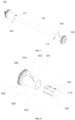
- FIG. 2 representatively shows a schematic three-dimensional exploded view of the cleaning brush
- FIG. 3 representatively shows a front view of FIG. 1
- FIG. 4 representatively shows a sectional view of a shaft side of FIG. 3
- FIG. 5 representatively shows a front view of FIG. 2
- FIG. 6 representatively shows a sectional view of a shaft side of FIG. 5
- FIG. 7 representatively shows a schematic diagram of a three-dimensional structure of the shaft rod 100 and the end members 300;
- FIG. 8 representatively shows an enlarged schematic diagram of an exploded state of part of the structure shown in FIG. 7 , and specifically shows an exploded state of one end member 300 and one first end 110 of the shaft rod.
- the shaft rod 100 has two first ends 110 opposite in an axial direction, that is, two ends of the shaft rod 100 are the first ends 110 respectively.
- the cylindrical member 200 coaxially sleeves the shaft rod 100 and is provided with two second ends 210 opposite in an axial direction, that is, two ends of the cylindrical member 200 are second ends 210 respectively.
- a brush piece is arranged on an outer surface of the cylindrical member 200.
- the two end members 300 are installed on the two first ends 110 of the shaft rod 100 respectively.
- Each end member 300 is provided with a blocking structure 310 capable of preventing an entanglement such as hairs and silk threads from excessively extending away from the cleaning brush.
- the end member 300 and the first end 110 corresponding to the end member 300 are provided with installation structures 400 matching each other respectively.
- the second end 210 of the cylindrical member 200 which corresponds to the end member 300, covers at least a portion of the end member 300, see a coverage area A shown in FIG. 4 for details.
- the cleaning brush proposed in the present disclosure includes at least one end member 300, the at least one end member 300 being installed on at least one first end 110 of the shaft rod 100.
- the second end 210 of the cylindrical member 200 which corresponds to the end member 300, may cover the first end 110, on which the end member 300 is installed.
- the first end 110 on which the end member 300 is installed is all located within a coverage range of the second end 210 corresponding to the first end, that is, the first end 110 does not extend out of the second end 210, and also the length of the shaft rod 100 is less than the length of the cylindrical member 200.
- the first end 110 on which the end member 300 is installed may also partially extend out of the coverage range of the corresponding second end 210, that is, the first end 110 may extend out of the coverage area A shown in FIG. 4 , but is not limited thereto in this implementation, as long as it is ensured that the second end 210 covers at least part of the end member 300.
- the blocking structure 310 of the end member 300 may be located outside the second end 210 of the cylindrical member 200, which corresponds to the end member 300. In other words, the blocking structure 310 of the end member 300 may be located outside the coverage area A shown in FIG. 4 .
- the installation structure 400 may include a guide hole 411 and a guide shaft 412.
- the guide hole 411 is coaxially formed in an end surface of the first end 110.
- the guide shaft 412 is connected to the end member 300 and used for being inserted into the guide hole 411.
- the guide shaft 412 and the guide hole 411 cooperate with each other by means of insertion, so that an axial guidance function and a radial limiting function are provided in the installation of the end members 300 and the shaft rod 100 in the present disclosure.
- the installation structure 400 may further include a guide sleeve 420.
- the guide sleeve 420 is arranged at an end of the end member 300 facing the shaft rod 100 and can sleeve the first end 110.
- a sidewall of the first end 110 is provided with a first limiting structure
- an inner wall of the guide sleeve 420 is provided with a second limiting structure matching the first limiting structure. Accordingly, the cleaning brush can achieve no relative rotation between the shaft rod 100 and the end members 300 by means of the cooperation between the first limiting structure and the second limiting structure.
- the installation structure 400 may include a guide hole 411, a guide shaft 412 and a guide sleeve 420 at the same time.
- the guide sleeve 420 may be arranged around the periphery of at least part of sections of the guide shaft 412 at intervals.
- the installation structure 400 may also include a guide hole 411 and a guide shaft 412 only, or a guide sleeve 420 alone, or realize installation and fixation of the end member 300 and the first end 110 of the shaft rod 100 by means of other structures.
- the distance L1 between the blocking structure 310 corresponding to the same first end 110 and an end of the guide sleeve 420 away from the end member 300 may account for more than 5%, e.g., 5%, 8%, 10% or 15% of the length L0 of the shaft rod 100.
- the cleaning brush of the present disclosure is characterized in that through the design that the guide sleeve 420 partially intervenes between the first end 110 and the second end 210, each end member 300 has a relatively large size (including a size of the guide sleeve 420), so as to increase a space of the end member 300 for an entanglement to wind, and further prevent the entanglement from being wound to the shaft rod 100.
- the design of a length relationship of the above related members is adopted, so that the length of a part of each end member 300 which matches the shaft rod 100 is extended, resulting in a size increase and easy processing and production.
- the first limiting structure may be a limiting groove 431
- the second limiting structure may be a limiting rib 432
- the limiting groove 431 matches the limiting rib 432 in shape. Accordingly, in the process of the guide sleeve 420 sleeving the first end 110 of the shaft rod 100, the limiting rib 432 and the limiting groove 431 cooperate with each other to provide guiding and limiting functions during the above installation process.
- the first limiting structure may also be a limiting rib 432
- the second limiting structure may also be a limiting groove 431.
- one of the first limiting structure and the second limiting structure may be a limiting rib 432, and the other may be a limiting groove 431 whose shape matches that of the limiting rib 432.
- the first limiting structure and the second limiting structure can also adopt other forms of limiting cooperation structures, but are not limited to this.
- the limiting rib 432 and the limiting groove 431 are in spiral shapes which match each other. Accordingly, in the disassembly and assembly processes of the end members 300 and the shaft rod 100, a relative displacement in an axial direction and a relative rotation in a circumferential direction exist therebetween.
- a spiral direction of the spiral limiting rib 432 and the spiral limiting groove 431 may be opposite to a rotation direction of the shaft rod 100.
- an outer wall of the guide sleeve 420 may be provided with at least one first assembly identifier 421 which can mark a rotation direction (i.e., the spiral direction of the limiting rib 432 and the limiting groove 431) when the end members 300 and the shaft rod 100 are assembled.
- the outer wall of the guide sleeve 420 may be provided with a deformation groove, which can prevent a shrinkage deformation of injection molded parts such as the guide sleeve 420 and the end members 300.
- the deformation groove may adopt a special shape, e.g., approximately a triangle, an arrow, etc., as the first assembly identifier 421 to mark the rotation direction when the end members 300 and the shaft rod 100 are assembled while preventing the shrinkage deformation.
- the limiting rib 432 may be arranged on an inner wall of the guide sleeve 420 through an integrated molding process in a case that the second limiting structure is the limiting rib 432.
- the limiting rib 432 may also be arranged on the inner wall of the guide sleeve 420 through other processes, e.g., by welding, or formed from part of the structure of the guide sleeve 420 by stamping, etc.
- a limiting groove 431 may be a groove formed in the inner wall of the guide sleeve 420 or a through groove penetrating through the guide sleeve 420, in a case that the second limiting structure is the limiting groove 431.
- the first end 110 may be provided with a plurality of first limiting structures, which is uniformly arranged at intervals in a circumferential direction of the shaft rod 100.
- the guide sleeve 420 may be provided with a plurality of the second limiting structures, which is uniformly arranged at intervals in a circumferential direction of the guide sleeve 420.
- the number of the limiting rib 432 may be one or more, and the number of the limiting ribs 432 is not greater than the number of the limiting grooves 431, but may be less than the number of the limiting grooves 431.
- the outer wall of the guide sleeve 420 may be provided with at least one second assembly identifier 422, and the at least one second assembly identifier 422 may correspond to at least one second limiting structure in position and accordingly is capable of marking a position of the at least one second limiting structure.
- the outer wall of the guide sleeve 420 may be provided with only one second assembly identifier 422 which corresponds to any second limiting structure; or the outer wall of the guide sleeve 420 may be provided with a plurality of second assembly identifiers 422 which correspond to the plurality of second limiting structures respectively.
- each end member 300 may be a blocking ring which may surround the outer circumference of the end member 300 and is a closed-loop structure.
- the end member 300 is installed on each of the two first ends 110 of the shaft rod 100.
- one of the two end members 300 is provided with a transmission structure 320, the transmission structure 320 being used to transmit a torque.
- the other of the two end members 300 is used for installation of a bearing structure 500.
- the end member 300 provided with the transmission structure 320 is connected to a driving mechanism of the cleaning device through the transmission structure 320, and the end member 300 on which the bearing structure 500 is installed is rotatably connected to other structures (e.g., a device body) of the cleaning device through the bearing structure 500.
- the driving side end cover rotates around the guide hole 411.
- the driving side end cover may move in an axial direction while rotating, thereby completing the entire assembly and disassembly of the end cover.
- the bearing side end cover may also be assembled and disassembled according to the same movement logic.
- the transmission structure 320 may include a columnar structure with a regularly polygonal cross-section, an axis of the columnar structure coinciding with an axis of the end member 300 and an axis of the shaft rod 100, the transmission structure being accordingly used to cooperate with an output end of a driving mechanism, e.g., a final-stage output gear of a gearbox.
- a driving mechanism e.g., a final-stage output gear of a gearbox.
- an end of the guide shaft 412 arranged on the end member 300 which is away from the shaft rod 100, extends out of the end member 300 and serves as a matching section 4121 matching the bearing structure 500; and the bearing structure 500 is detachably arranged on the matching section 4121 of the guide shaft 412.
- the matching section 4121 of the guide shaft 412 may be provided with a positioning groove 4122 in a circumferential direction.
- the outer diameter of the matching section 4121 is designed to be smaller than the outer diameter of other section of the guide shaft 412, such that the matching section 4121 forms the positioning groove 4122.
- the positioning groove 4122 cooperates with the bearing structure 500 by fixing each other's positions for preventing the bearing structure 500 from displacing.
- a friction structure 300 for example, but not limited to friction lines or fraction bulges, may be arranged on the end member 300, such that it is easier to screw the end member 300 during assembly.
- the cylindrical member 200 may be a flexible member or a rigid member.
- the brush piece may be arranged on the outer surface of the cylindrical member 200 by means of sticking, insertion and the like.
- the cylindrical member 200 is the flexible member, the brush piece and the cylindrical member 200 may also be integrally formed.
- the brush piece may also be a blade, bristles or in other forms.
- the first end is provided with a plurality of the first limiting structures, which is uniformly arranged at intervals in a circumferential direction of the shaft rod.
- the guide sleeve is provided with a plurality of the second limiting structures, which is uniformly arranged at intervals in a circumferential direction of the guide sleeve.
- the outer wall of the guide sleeve is provided with at least one second assembly identifier, the at least one second assembly identifier corresponding to the at least one second limiting structure in position and used for marking a position of the at least one second limiting structure.
- the blocking structure is a blocking ring, the blocking ring surrounding the outer circumference of the end member and being a closed-loop structure.
- the end member is installed on each of the two first ends of the shaft rod, one of the two end members is provided with a transmission structure, and the other is used for installation of a bearing structure.
- the transmission structure includes a columnar structure with a regularly polygonal cross-section, an axis of the columnar structure coinciding with an axis of the end member and an axis of the shaft rod; and the transmission structure is used to cooperate with an output end of a driving mechanism.
- one end of the guide shaft of one of the end members which is away from the shaft rod, extends out of the end member and serves as a matching section matching the bearing structure; and the bearing structure is detachably arranged on the matching section of the guide shaft.
- the matching section is provided with a positioning groove in a circumferential direction, the positioning groove cooperating with the bearing structure by fixing each other's positions to prevent the bearing structure from displacing.
- the cylindrical member may be a flexible member or a rigid member.
- the intelligent cleaning device proposed in the present disclosure includes a cleaning brush proposed in the present disclosure and detailed in the above implementations.
- the cleaning brush purposed by the present disclosure includes the shaft rod 100, the cylindrical member 200 and the end members 300.
- Each end member 300 is installed on the first end 110 of the shaft rod 100.
- Each end member 300 is provided with the blocking structure 310 for preventing an entanglement from excessively extending away from the cleaning brush.
- the end member 300 and the first end 110 are provided with installation structures 400 matching each other respectively.
- the second end 210 of the cylindrical member 200 which corresponds to the end member 300, covers at least a portion of the end member 300.
Landscapes
- Engineering & Computer Science (AREA)
- Mechanical Engineering (AREA)
- Cleaning In General (AREA)
- Brushes (AREA)
- Feeding Of Articles By Means Other Than Belts Or Rollers (AREA)
- Cleaning Implements For Floors, Carpets, Furniture, Walls, And The Like (AREA)
Abstract
Description
- The present disclosure claims priority to
Chinese Patent Application No. 202210022939.2 filed on January 10, 2022 - The present disclosure relates to the field of cleaning device technologies, and particularly, to a cleaning brush and an intelligent cleaning device.
- A cleaning brush is an important functional part of a cleaning device. An end cover of the cleaning brush is used to block an entanglement such as hairs or silk threads wound during a working process of the cleaning device, so as to avoid the phenomenon of jamming of a power output end and a bearing end of a motor due to entanglement because of excessive extension of the entanglement to the end of the cleaning brush.
- An end cover of the existing cleaning brush has a relatively small size, such that a longer end of a shaft rod of the cleaning brush is exposed outside the end cover; and the end cover is located outside a cylindrical member sleeving a shaft cover of the cleaning brush. Consequently, it is easy for an entanglement wound around the cylindrical member to wind from the end of the cylindrical member to the end of the shaft rod, resulting in a relatively deep entangling position. In addition, the end cover must be detached to remove the entanglement from the inside of the cylinder member, which is laborious. In addition, due to the relatively small size of the end cover of the existing cleaning brush, it is difficult to find the missing installation of the end cover of the cleaning brush in the assembly process, so it is necessary to provide a responsible missing-installation prevention structure.
- A main object of the present disclosure is to overcome at least one defect of the prior art, a cleaning brush that may prevent the entanglement from being wound to the shaft rod and is convenient for cleaning the entanglement is provided.
- Another object of the present disclosure is to overcome at least one defect of the prior art, and an intelligent cleaning device including the above cleaning brush is provided.
- To this end, the present disclosure adopts the following technical solutions.
- According to an aspect of the present disclosure, a cleaning brush is provided. The cleaning brush includes a shaft rod, a cylindrical member and at least one end member, wherein the shaft rod is provided with two first ends opposite in an axial direction; the cylindrical member coaxially sleeves the shaft rod and is provided with two second ends opposite in an axial direction, and a brush piece is arranged on an outer surface of the cylindrical member; the at least one end member is installed on at least one of the first ends, and the end member is provided with a blocking structure for preventing an entanglement from excessively extending away from the cleaning brush; the end member and the first end are provided with installation structures matching each other respectively; and the second end of the cylindrical member, which corresponds to the end member, covers at least a portion of the end member.
- According to one implementation of the present disclosure, the second end of the cylindrical member, which corresponds to the end member, covers the first end on which the end member is installed.
- According to one implementation of the present disclosure, the blocking structure of the end member is located outside the second end of the cylindrical member, which corresponds to the end member.
- According to one implementation of the present disclosure, the installation structure includes a guide hole and a guide shaft. A guide hole is coaxially formed in an end surface of the first end; and the guide shaft is connected to the end member and used for being inserted into the guide hole.
- According to one implementation of the present disclosure, the installation structure includes a guide sleeve. The guide sleeve is arranged at an end of the end member facing the shaft rod and used for sleeving the first end; a sidewall of the first end is provided with at least one first limiting structure; and an inner wall of the guide sleeve is provided with at least one second limiting structure matching the at least one first limiting structure.
- According to one implementation of the present disclosure, along the axial direction of the shaft rod, a distance between the blocking structure corresponding to the same first end and an end of the guide sleeve away from the end member accounts for more than 5% of the length of the shaft rod.
- According one implementation of the present disclosure, one of the first limiting structure and the second limiting structure is a limiting rib, and the other is a limiting groove, the limiting rib matching the limiting groove in shape.
- According to one implementation of the present disclosure, the limiting rib and the limiting groove are in spiral shapes matching each other.
- According to one implementation of the present disclosure, a spiral direction of the spiral limiting rib and the spiral limiting groove is opposite to a rotation direction of the shaft rod.
- According to one implementation of the present disclosure, an outer wall of the guide sleeve is provided with at least one first assembly identifier used for marking a rotation direction of the end member while being assembled with the shaft rod.
- According to one implementation of the present disclosure, the second limiting structure is the limiting rib, the limiting rib being arranged on the inner wall of the guide sleeve by welding or an integrated molding process, or being formed from a part of structure of the guide sleeve through a stamping process; or the second limiting structure is the limiting groove, the limiting groove being a groove formed in the inner wall of the guide sleeve, or being a through groove penetrating through the guide sleeve.
- According to one implementation of the present disclosure, the first end is provided with a plurality of the first limiting structures, which is uniformly arranged at intervals in a circumferential direction of the shaft rod.
- According to one implementation of the present disclosure, the guide sleeve is provided with a plurality of the second limiting structures, which is uniformly arranged at intervals in a circumferential direction of the guide sleeve.
- According to one implementation of the present disclosure, the outer wall of the outer wall of the guide sleeve is provided with at least one second assembly identifier, the at least one second assembly identifier corresponding to the at least one second limiting structure in position and used for marking a position of the at least one second limiting structure.
- According to one implementation of the present disclosure, the blocking structure is a blocking ring, the blocking ring surrounding the outer circumference of the end member and being a closed-loop structure.
- According to one implementation of the present disclosure, the end member is installed one each of the two first ends of the shaft rod, one of the two end members is provided with a transmission structure, and the other is used for installation of a bearing structure.
- According to one implementation of the present disclosure, the transmission structure includes a columnar structure with a regularly polygonal cross-section, an axis of the columnar structure coinciding with an axis of the end member and an axis of the shaft rod; and the transmission structure is used to cooperate with an output end of a driving mechanism.
- According to one implementation of the present disclosure, an end of the guide shaft of the end member, which is away from the shaft rod, extends out of the end member and serves as a matching section matching the bearing structure; and the bearing structure is detachably arranged on the matching section of the guide shaft.
- According to one implementation of the present disclosure, the matching section is provided with a positioning groove in a circumferential direction, the positioning groove cooperating with the bearing structure by fixing each other's positions to prevent the bearing structure from displacing.
- According to one implementation of the present disclosure, the cylindrical member is a flexible member or a rigid member.
- According to another aspect of the present disclosure, an intelligent cleaning device is provided, which includes the cleaning brush proposed in the present disclosure and described in the above implementations.
- From the above technical solutions, it can be seen that the cleaning brush and the intelligent cleaning device proposed in the present disclosure have the following advantages and positive effects.
- The cleaning brush provided by the present disclosure includes the shaft rod, the cylindrical member and the end member. The end member is installed on the first end. The end member is provided with the blocking structure used for preventing an entanglement from excessively extending away from the cleaning brush. The end member and the first end are provided with installation structures matching each other respectively. The second end of the cylindrical member, which corresponds to the end member, covers at least a portion of the end member. With the above design, in the present disclosure, at least a portion of the end member intervenes between the shaft rod and the corresponding end of the cylindrical member, avoiding an entanglement wound on the cylindrical member from being wound to the shaft rod directly. Instead, the entanglement is wound on the end member and can thus be removed with the disassembly of the end member, such that cleaning is more convenient.
- Various objects, features, and advantages of the present disclosure will become more apparent by considering the following detailed description of preferred embodiments of the present disclosure in conjunction with the accompanying drawings. The accompanying drawings are merely exemplary illustrations of the present disclosure, and are not necessarily drawn to scale. In the accompanying drawings, the same reference numerals always refer to the same or similar components, in which:
-
FIG. 1 is a schematic diagram of a three-dimensional structure of a cleaning brush shown according to an exemplary embodiment; -
FIG. 2 is a schematic three-dimensional exploded view of the cleaning brush shown inFIG. 1 ; -
FIG. 3 is a front view ofFIG. 1 ; -
FIG. 4 is a sectional view of a shaft side ofFIG. 3 ; -
FIG. 5 is a front view ofFIG. 2 ; -
FIG. 6 is a sectional view of a shaft side ofFIG. 5 ; -
FIG. 7 is a schematic diagram of a three-dimensional structure of a shaft rod and an end member of the cleaning brush shown inFIG. 1 ; -
FIG. 8 is an enlarged schematic diagram of an exploded state of part of the structure shown inFIG. 7 . - Reference numerals represent the following components:
- 100: shaft rod;
- 110: first end;
- 200: cylindrical member;
- 210: second end;
- 300: end member;
- 310: blocking structure;
- 320: transmission structure;
- 330: friction structure;
- 400: installation structure;
- 411: guide hole;
- 412: guide shaft;
- 4121: matching section;
- 4122: positioning groove;
- 420: guide sleeve;
- 421: first assembly identifier;
- 422: second assembly identifier;
- 431: limiting groove;
- 432: limiting rib;
- 500: bearing structure;
- A: coverage area;
- L0: length;
- L1: distance.
- Typical embodiments embodying the features and advantages of the present disclosure will be described in detail in the following description. It should be understood that the present disclosure can have various variations in different embodiments, none of which departs from the scope of the present disclosure; and the descriptions and drawings therein are essentially for illustrative purposes and not intended to limit the present disclosure.
- The following description of different exemplary embodiments of the present disclosure is given with reference to the accompanying drawings. The accompanying drawings form a part of the present disclosure, and different exemplary structures, systems and steps that may implement a plurality of aspects of the present disclosure are shown in examples. It should be understood that other specific schemes of components, structures, exemplary apparatuses, systems and steps may be used, and structural and functional modifications may be made without departing from the scope of the present disclosure. Further, although the terms "above", "between", "within" and the like may be used in the present description to describe different exemplary features and components of the present disclosure, but these terms are used herein only for convenience, for example, according to orientations in examples described in the accompanying drawings. Nothing in the present description should be construed to mean that a particular three-dimensional orientation of the structure is required to fall within the scope of the present disclosure.
- Referring to
FIG. 1 , a schematic diagram of a three-dimensional structure of a cleaning brush proposed in the present disclosure is representatively shown. In this exemplary implementation, the cleaning brush proposed in the present disclosure is illustrated by taking an example of being applied to an intelligent cleaning robot. As easily understood by a person skilled in the art, in order to apply relevant designs of the present disclosure to other types of cleaning devices, various modifications, additions, replacements, deletions or other changes are made to the following specific implementations, but these changes still fall within the scope of the principles of the cleaning brush proposed in the present disclosure. - As shown in
FIG. 1 , in this implementation, the cleaning brush proposed in the present disclosure mainly includes a shaft rod 100 (not shown in the figure), acylindrical member 200 and twoend members 300. Referring toFIGs. 2 to 8 ,FIG. 2 representatively shows a schematic three-dimensional exploded view of the cleaning brush;FIG. 3 representatively shows a front view ofFIG. 1 ;FIG. 4 representatively shows a sectional view of a shaft side ofFIG. 3 ;FIG. 5 representatively shows a front view ofFIG. 2 ;FIG. 6 representatively shows a sectional view of a shaft side ofFIG. 5 ;FIG. 7 representatively shows a schematic diagram of a three-dimensional structure of theshaft rod 100 and theend members 300; andFIG. 8 representatively shows an enlarged schematic diagram of an exploded state of part of the structure shown inFIG. 7 , and specifically shows an exploded state of oneend member 300 and onefirst end 110 of the shaft rod. The structures, connection modes and functional relationships of main components of the cleaning brush proposed in the present disclosure will be described in detail below in conjunction with the above accompanying drawings. - As shown in
FIGs. 1 to 4 , in one implementation of the present disclosure, theshaft rod 100 has twofirst ends 110 opposite in an axial direction, that is, two ends of theshaft rod 100 are the first ends 110 respectively. Thecylindrical member 200 coaxially sleeves theshaft rod 100 and is provided with twosecond ends 210 opposite in an axial direction, that is, two ends of thecylindrical member 200 aresecond ends 210 respectively. A brush piece is arranged on an outer surface of thecylindrical member 200. The twoend members 300 are installed on the twofirst ends 110 of theshaft rod 100 respectively. Eachend member 300 is provided with a blockingstructure 310 capable of preventing an entanglement such as hairs and silk threads from excessively extending away from the cleaning brush. In addition, theend member 300 and thefirst end 110 corresponding to theend member 300 are provided withinstallation structures 400 matching each other respectively. On this basis, thesecond end 210 of thecylindrical member 200, which corresponds to theend member 300, covers at least a portion of theend member 300, see a coverage area A shown inFIG. 4 for details. With the above design, in the present disclosure, at least part of theend member 300 intervenes between theshaft rod 110 and the corresponding end of thecylindrical member 200, avoiding an entanglement wound on thecylindrical member 200 from being wound to theshaft rod 100. Instead, the entanglement is wound on theend members 300 and can thus be removed with the disassembly of theend members 300, such that cleaning is more convenient. In addition, during the assembly process of the cleaning brush, it is easier to find that the cleaning brush is provided with noend member 300 if theend member 300 is not assembled. - It should be noted that each implementation of the present description is illustrated by taking the two
first ends 110 of theshaft rod 100 being provided with theend members 300 respectively as an example. It should be understood that in some implementations, it is also possible to install anend member 300 only on onefirst end 110 of theshaft rod 100 in the present disclosure. In other words, in various possible implementations conforming to the design conception of the present disclosure, the cleaning brush proposed in the present disclosure includes at least oneend member 300, the at least oneend member 300 being installed on at least onefirst end 110 of theshaft rod 100. - As shown in
FIGs. 2 ,4 and6 , in one implementation of the present disclosure, thesecond end 210 of thecylindrical member 200, which corresponds to theend member 300, may cover thefirst end 110, on which theend member 300 is installed. In other words, thefirst end 110 on which theend member 300 is installed is all located within a coverage range of thesecond end 210 corresponding to the first end, that is, thefirst end 110 does not extend out of thesecond end 210, and also the length of theshaft rod 100 is less than the length of thecylindrical member 200. In some implementations, thefirst end 110 on which theend member 300 is installed may also partially extend out of the coverage range of the correspondingsecond end 210, that is, thefirst end 110 may extend out of the coverage area A shown inFIG. 4 , but is not limited thereto in this implementation, as long as it is ensured that thesecond end 210 covers at least part of theend member 300. - As shown in
FIGs. 1 to 6 , in one implementation of the present disclosure, the blockingstructure 310 of theend member 300 may be located outside thesecond end 210 of thecylindrical member 200, which corresponds to theend member 300. In other words, the blockingstructure 310 of theend member 300 may be located outside the coverage area A shown inFIG. 4 . - As shown in
FIGs. 2 ,FIG. 4 andFIG. 6 , in one implementation of the present disclosure, theinstallation structure 400 may include aguide hole 411 and aguide shaft 412. Specifically, theguide hole 411 is coaxially formed in an end surface of thefirst end 110. Theguide shaft 412 is connected to theend member 300 and used for being inserted into theguide hole 411. With the above design, theguide shaft 412 and theguide hole 411 cooperate with each other by means of insertion, so that an axial guidance function and a radial limiting function are provided in the installation of theend members 300 and theshaft rod 100 in the present disclosure. - As shown in
FIGs. 1 to 6 , in one implementation of the present disclosure, theinstallation structure 400 may further include aguide sleeve 420. Specifically, theguide sleeve 420 is arranged at an end of theend member 300 facing theshaft rod 100 and can sleeve thefirst end 110. On this basis, a sidewall of thefirst end 110 is provided with a first limiting structure, and an inner wall of theguide sleeve 420 is provided with a second limiting structure matching the first limiting structure. Accordingly, the cleaning brush can achieve no relative rotation between theshaft rod 100 and theend members 300 by means of the cooperation between the first limiting structure and the second limiting structure. - In addition, as shown in
FIGs. 2 ,FIG. 4 andFIG. 6 , in one implementation of the present disclosure, theinstallation structure 400 may include aguide hole 411, aguide shaft 412 and aguide sleeve 420 at the same time. On this basis, theguide sleeve 420 may be arranged around the periphery of at least part of sections of theguide shaft 412 at intervals. In some implementations, theinstallation structure 400 may also include aguide hole 411 and aguide shaft 412 only, or aguide sleeve 420 alone, or realize installation and fixation of theend member 300 and thefirst end 110 of theshaft rod 100 by means of other structures. - As shown in
FIG. 4 , in one implementation of the present disclosure, along the axial direction of theshaft rod 100, the distance L1 between the blockingstructure 310 corresponding to the samefirst end 110 and an end of theguide sleeve 420 away from theend member 300 may account for more than 5%, e.g., 5%, 8%, 10% or 15% of the length L0 of theshaft rod 100. Accordingly, compared with the existing cleaning brush in which an end cover has a relatively small size, the cleaning brush of the present disclosure is characterized in that through the design that theguide sleeve 420 partially intervenes between thefirst end 110 and thesecond end 210, eachend member 300 has a relatively large size (including a size of the guide sleeve 420), so as to increase a space of theend member 300 for an entanglement to wind, and further prevent the entanglement from being wound to theshaft rod 100. In other words, according to the present disclosure, the design of a length relationship of the above related members is adopted, so that the length of a part of eachend member 300 which matches theshaft rod 100 is extended, resulting in a size increase and easy processing and production. - As shown in
FIGs. 6 and8 , in one implementation of the present disclosure, the first limiting structure may be a limitinggroove 431, the second limiting structure may be a limitingrib 432, and the limitinggroove 431 matches the limitingrib 432 in shape. Accordingly, in the process of theguide sleeve 420 sleeving thefirst end 110 of theshaft rod 100, the limitingrib 432 and the limitinggroove 431 cooperate with each other to provide guiding and limiting functions during the above installation process. In some implementations, the first limiting structure may also be a limitingrib 432, and the second limiting structure may also be a limitinggroove 431. In other words, in various possible implementations conforming to the design conception of the present disclosure, one of the first limiting structure and the second limiting structure may be a limitingrib 432, and the other may be a limitinggroove 431 whose shape matches that of the limitingrib 432. In addition, the first limiting structure and the second limiting structure can also adopt other forms of limiting cooperation structures, but are not limited to this. - As shown in
FIG. 6 andFIG. 8 , in one implementation of the present disclosure, the limitingrib 432 and the limitinggroove 431 are in spiral shapes which match each other. Accordingly, in the disassembly and assembly processes of theend members 300 and theshaft rod 100, a relative displacement in an axial direction and a relative rotation in a circumferential direction exist therebetween. - Based on the design of the spiral shape of the limiting
rib 432 and the limitinggroove 431, in one implementation of the present disclosure, a spiral direction of thespiral limiting rib 432 and thespiral limiting groove 431 may be opposite to a rotation direction of theshaft rod 100. With the above design, in a case that theshaft rod 100 rotates in the cleaning device in a rotation direction, the limitingrib 432 can be further prevented from being disengaged from the limitinggroove 431 as the spiral direction of the limitingrib 432 and the limitinggroove 431 is opposite to this rotation direction, thereby ensuring the installation stability and reliability of theshaft rod 100 and theend members 300. - As shown in
FIG. 7 and FIG. 8 , based on the design of the spiral design of the limitingrib 432 and the limitinggroove 431, in one implementation of the present disclosure, an outer wall of theguide sleeve 420 may be provided with at least onefirst assembly identifier 421 which can mark a rotation direction (i.e., the spiral direction of the limitingrib 432 and the limiting groove 431) when theend members 300 and theshaft rod 100 are assembled. - As shown in
FIG. 7 and FIG. 8 , based on the design that theguide sleeve 420 is provided with thefirst assembly identifier 421, in one implementation of the present disclosure, the outer wall of theguide sleeve 420 may be provided with a deformation groove, which can prevent a shrinkage deformation of injection molded parts such as theguide sleeve 420 and theend members 300. On this basis, the deformation groove may adopt a special shape, e.g., approximately a triangle, an arrow, etc., as thefirst assembly identifier 421 to mark the rotation direction when theend members 300 and theshaft rod 100 are assembled while preventing the shrinkage deformation. - As shown in
FIG. 4 andFIG. 6 , in one implementation of the present disclosure, the limitingrib 432 may be arranged on an inner wall of theguide sleeve 420 through an integrated molding process in a case that the second limiting structure is the limitingrib 432. In one implementation, the limitingrib 432 may also be arranged on the inner wall of theguide sleeve 420 through other processes, e.g., by welding, or formed from part of the structure of theguide sleeve 420 by stamping, etc. Moreover, a limitinggroove 431 may be a groove formed in the inner wall of theguide sleeve 420 or a through groove penetrating through theguide sleeve 420, in a case that the second limiting structure is the limitinggroove 431. - In one implementation of the present disclosure, the
first end 110 may be provided with a plurality of first limiting structures, which is uniformly arranged at intervals in a circumferential direction of theshaft rod 100. - In one implementation of the present disclosure, the
guide sleeve 420 may be provided with a plurality of the second limiting structures, which is uniformly arranged at intervals in a circumferential direction of theguide sleeve 420. - As described above, by taking the first limiting structure and the second limiting structure being the limiting
groove 431 and the limitingrib 432 respectively as an example, in a case of a plurality of limitinggrooves 431, the number of the limitingrib 432 may be one or more, and the number of the limitingribs 432 is not greater than the number of the limitinggrooves 431, but may be less than the number of the limitinggrooves 431. - As shown in
FIG. 5 andFIG. 8 , in one implementation of the present disclosure, the outer wall of theguide sleeve 420 may be provided with at least onesecond assembly identifier 422, and the at least onesecond assembly identifier 422 may correspond to at least one second limiting structure in position and accordingly is capable of marking a position of the at least one second limiting structure. In some implementations, in a case that the inner wall of theguide sleeve 420 is provided with a plurality of second limiting structures, the outer wall of theguide sleeve 420 may be provided with only onesecond assembly identifier 422 which corresponds to any second limiting structure; or the outer wall of theguide sleeve 420 may be provided with a plurality ofsecond assembly identifiers 422 which correspond to the plurality of second limiting structures respectively. - As shown in
FIGs. 1 to 6 , in one implementation of the present disclosure, the blockingstructure 310 of eachend member 300 may be a blocking ring which may surround the outer circumference of theend member 300 and is a closed-loop structure. - As shown in
FIGs. 1 to 7 , in one implementation of the present disclosure, theend member 300 is installed on each of the twofirst ends 110 of theshaft rod 100. On this basis, one of the twoend members 300 is provided with atransmission structure 320, thetransmission structure 320 being used to transmit a torque. The other of the twoend members 300 is used for installation of abearing structure 500. On this basis, theend member 300 provided with thetransmission structure 320 is connected to a driving mechanism of the cleaning device through thetransmission structure 320, and theend member 300 on which thebearing structure 500 is installed is rotatably connected to other structures (e.g., a device body) of the cleaning device through the bearingstructure 500. Accordingly, in a case that the end member 300 (i.e., a driving side end cover) provided with thetransmission structure 320 is installed, the driving side end cover rotates around theguide hole 411. In addition, due to thespiral limiting groove 431 and thespiral limiting rib 432, the driving side end cover may move in an axial direction while rotating, thereby completing the entire assembly and disassembly of the end cover. Similarly, in a case that the end member 300 (i.e., a bearing side end cover) for installation of thebearing structure 500 is installed, the bearing side end cover may also be assembled and disassembled according to the same movement logic. Meanwhile, since the spiral direction of thespiral limiting rib 432 and thespiral limiting groove 431 is opposite to the rotation direction of the shaft rod 100 (i.e., a working direction of a main brush), spiral loosening will not occur during work. With the above design, in the assembly process of the cleaning brush, cooperation structures (e.g., laminated structures and bearing structures 500) installed or provided on the twoend members 300 respectively are not disposed in a case that theend members 300 are not assembled, such that main brush parts (e.g., theshaft rod 100 and the cylindrical member 200) cannot be installed in place after missing installation of theend members 300, thereby achieving a more thorough missing installation prevention function. In addition, in a case that theend members 300 are installed at the twofirst ends 110 of theshaft rod 100 respectively, hesame installation structure 400 is adopted between the twofirst ends 110 of theshaft rod 100 and between the twoend members 300, which is convenient for foolproof production, thereby being conducive to reducing a processing error rate and increasing a production yield. - As shown in
FIG. 1 and FIG. 2 , based on the design that oneend member 300 is provided with thetransmission structure 320, in one implementation of the present disclosure, thetransmission structure 320 may include a columnar structure with a regularly polygonal cross-section, an axis of the columnar structure coinciding with an axis of theend member 300 and an axis of theshaft rod 100, the transmission structure being accordingly used to cooperate with an output end of a driving mechanism, e.g., a final-stage output gear of a gearbox. - As shown in
FIGs. 2 to 6 , based on the design that the bearingstructure 500 is installed on theother end member 300, in one implementation of the present disclosure, an end of theguide shaft 412 arranged on theend member 300, which is away from theshaft rod 100, extends out of theend member 300 and serves as amatching section 4121 matching thebearing structure 500; and thebearing structure 500 is detachably arranged on thematching section 4121 of theguide shaft 412. - As shown in
FIG. 5 and FIG. 6 , based on the design that theguide shaft 412 is provided with thematching section 4121, in one implementation of the present disclosure, thematching section 4121 of theguide shaft 412 may be provided with apositioning groove 4122 in a circumferential direction. For example, the outer diameter of thematching section 4121 is designed to be smaller than the outer diameter of other section of theguide shaft 412, such that thematching section 4121 forms thepositioning groove 4122. On this basis, thepositioning groove 4122 cooperates with the bearingstructure 500 by fixing each other's positions for preventing thebearing structure 500 from displacing. - As shown in
FIG. 8 , in one implementation of the present disclosure, afriction structure 300, for example, but not limited to friction lines or fraction bulges, may be arranged on theend member 300, such that it is easier to screw theend member 300 during assembly. - In one implementation of the present disclosure, the
cylindrical member 200 may be a flexible member or a rigid member. In addition, the brush piece may be arranged on the outer surface of thecylindrical member 200 by means of sticking, insertion and the like. In a case that thecylindrical member 200 is the flexible member, the brush piece and thecylindrical member 200 may also be integrally formed. In some implementations, the brush piece may also be a blade, bristles or in other forms. - It should be noted herein that the cleaning brush shown in the drawings and described in the present description is only a few examples of many types of cleaning brushes capable of adopting the principles of the present disclosure. It should be clearly understood that the principles of the present disclosure are in no way limited to any detail or any part of the cleaning brush shown in the drawings or described in the present description.
- For example:
in an implementation of the present disclosure, the first end is provided with a plurality of the first limiting structures, which is uniformly arranged at intervals in a circumferential direction of the shaft rod. - In an implementation of the present disclosure, the guide sleeve is provided with a plurality of the second limiting structures, which is uniformly arranged at intervals in a circumferential direction of the guide sleeve.
- In an implementation of the present disclosure, the outer wall of the guide sleeve is provided with at least one second assembly identifier, the at least one second assembly identifier corresponding to the at least one second limiting structure in position and used for marking a position of the at least one second limiting structure.
- In an implementation of the present disclosure, the blocking structure is a blocking ring, the blocking ring surrounding the outer circumference of the end member and being a closed-loop structure.
- In an implementation of the present disclosure, the end member is installed on each of the two first ends of the shaft rod, one of the two end members is provided with a transmission structure, and the other is used for installation of a bearing structure.
- In an implementation of the present disclosure, the transmission structure includes a columnar structure with a regularly polygonal cross-section, an axis of the columnar structure coinciding with an axis of the end member and an axis of the shaft rod; and the transmission structure is used to cooperate with an output end of a driving mechanism.
- In an implementation of the present disclosure, one end of the guide shaft of one of the end members, which is away from the shaft rod, extends out of the end member and serves as a matching section matching the bearing structure; and the bearing structure is detachably arranged on the matching section of the guide shaft.
- In an implementation of the present disclosure, the matching section is provided with a positioning groove in a circumferential direction, the positioning groove cooperating with the bearing structure by fixing each other's positions to prevent the bearing structure from displacing.
- In an implementation of the present disclosure, the cylindrical member may be a flexible member or a rigid member.
- Based on the above detailed description of several exemplary implementations of the cleaning brush proposed in the present disclosure, an exemplary implementation of the intelligent cleaning device proposed in the present disclosure will be described below.
- In one implementation of the present disclosure, the intelligent cleaning device proposed in the present disclosure includes a cleaning brush proposed in the present disclosure and detailed in the above implementations.
- It should be noted herein that the intelligent cleaning device shown in the drawings and described in the present description is only a few examples of many types of intelligent cleaning device capable of adopting the principles of the present disclosure. It should be clearly understood that the principles of the present disclosure are in no way limited to any detail or any part of the intelligent cleaning device shown in the drawings or described in the present description.
- In summary, the cleaning brush purposed by the present disclosure includes the
shaft rod 100, thecylindrical member 200 and theend members 300. Eachend member 300 is installed on thefirst end 110 of theshaft rod 100. Eachend member 300 is provided with the blockingstructure 310 for preventing an entanglement from excessively extending away from the cleaning brush. Theend member 300 and thefirst end 110 are provided withinstallation structures 400 matching each other respectively. Thesecond end 210 of thecylindrical member 200, which corresponds to theend member 300, covers at least a portion of theend member 300. With the above design, in the present disclosure, at least part of theend member 300 intervenes between theshaft rod 100 and the corresponding end of thecylindrical member 200, avoiding an entanglement wound on thecylindrical member 200 from being wound to theshaft rod 100. Instead, the entanglement is wound on theend member 300 and can thus be removed with the disassembly of theend member 300, such that cleaning is more convenient. - The exemplary implementations of the cleaning brush and the intelligent cleaning device proposed in the present disclosure are described and/or illustrated above in detail. However, the implementations of the present disclosure are not limited to the particular implementations described herein. On the contrary, components and/or steps of each implementation may be used independently and separately from the other components and/or steps described herein. Each component and/or each step in one implementation may also be used in conjunction with other components and/or steps of other implementations. In the course of introducing the elements/components/etc. described and/or illustrated herein, the terms "a/an", "one" and "the" are used to indicate the presence of one or more elements/components/etc. The terms "comprising", "including" and "provided with" are used to denote open-ended inclusion and means that additional elements/components/etc. may exist in addition to those listed. In addition, the terms "first" and "second" in the claims and description are used only as marks and are not numerical restrictions on their objects.
- Although the cleaning brush and the intelligent cleaning device proposed in the present disclosure have been described according to different particular embodiments, a person skilled in the art will recognize that the implementation of the present disclosure may be modified within the spirit and scope of the claims.
Claims (23)
- A cleaning brush, comprising:a shaft rod, provided with two first ends opposite in an axial direction;a cylindrical member, coaxially sleeving the shaft rod and provided with two second ends opposite in the axial direction, a brush piece being arranged on an outer surface of the cylindrical member; andat least one end member, installed on at least one of the first ends, the end member being provided with a blocking structure for preventing an entanglement from excessively extending away from the cleaning brush, the end member and the first end being provided with installation structures matching each other respectively, whereinthe second end, corresponding to the end member, of the cylindrical member, covers at least a portion of the end member.
- The cleaning brush according to claim 1, whereinthe second end, corresponding to the end member, of the cylindrical member, covers the first end with the end member installed thereon; and/orthe blocking structure of the end member is located outside the second end, corresponding to the end member, of the cylindrical member.
- The cleaning brush according to claim 1, wherein the installation structure comprises:a guide hole, coaxially defined in an end surface of the first end; anda guide shaft, connected to the end member and configured for being inserted into the guide hole.
- The cleaning brush according to any one of claim 1-3, wherein the installation structure comprises:a guide sleeve, arranged at an end of the end member facing the shaft rod and configured for sleeving the first end, whereina sidewall of the first end is provided with at least one first limiting structure, and an inner wall of the guide sleeve is provided with at least one second limiting structure matching the at least one first limiting structure.
- The cleaning brush according to claim 4, wherein a distance between the blocking structure and an end of the guide sleeve away from the end member is greater than 5% of a length of the shaft rod along the axial direction of the shaft rod, and the blocking structure and the guide sleeve correspond to a same first end.
- The cleaning brush according to claim 4, wherein one of the first limiting structure and the second limiting structure is a limiting rib, the other one of the first limiting structure and the second limiting structure is a limiting groove, and the limiting rib matches the limiting groove in shape.
- The cleaning brush according to claim 6, wherein the limiting rib and the limiting groove are in spiral shapes and match each other in shape.
- The cleaning brush according to claim 7, whereina spiral direction of the spiral limiting rib and the spiral limiting groove is opposite to a rotation direction of the shaft rod; and/oran outer wall of the guide sleeve is provided with at least one first assembly identifier for marking a rotation direction when the end member and the shaft rod are assembled.
- The cleaning brush according to claim 6, whereinthe second limiting structure is the limiting rib, the limiting rib is arranged on the inner wall of the guide sleeve by welding or an integrated molding process, or is formed from a part of structure of the guide sleeve through a stamping process; orthe second limiting structure is the limiting groove, the limiting groove is a groove defined in the inner wall of the guide sleeve, or is a through groove running through the guide sleeve.
- The cleaning brush according to claim 4, whereinthe first end is provided with a plurality of the first limiting structures uniformly arranged at intervals in a circumferential direction of the shaft rod; and/orthe guide sleeve is provided with a plurality of the second limiting structures uniformly arranged at intervals in a circumferential direction of the guide sleeve.
- The cleaning brush according to claim 4, wherein
the sidewall of the first end is provided with at least one third limiting structure, and the inner wall of the guide sleeve is provided with at least one fourth limiting structure matched with the third limiting structure; wherein, one of the third limiting structure and the fourth limiting structure is a bump clip, and the other one of the third limiting structure and the fourth limiting structure is a clamping slot matched with the bump clip. - The cleaning brush according to claim 11, wherein
the first end is provided with a plurality of first limiting structures and a plurality of third limiting structures, the plurality of first limiting structures and the plurality of third limiting structures are of equal quantity, wherein the plurality of first limiting structures and the plurality of third limiting structures are alternately arranged at intervals in sequence along a circumferential direction of the shaft rod. - The cleaning brush according to claim 12, wherein
the plurality of first limiting structures and the plurality of third limiting structures are uniformly arranged at intervals along the circumference direction of the shaft rod. - The cleaning brush according to claim 11, wherein
the guide sleeve is provided with a plurality of second limiting structures and a plurality of fourth limiting structures, the plurality of second limiting structures and the plurality of fourth limiting structures are of equal quantity, wherein the plurality of second limiting structures and the plurality of fourth limiting structures are alternately arranged at intervals in sequence along a circumferential direction of the guide sleeve. - The cleaning brush according to claim 14, wherein
the plurality of second limiting structures and the plurality of fourth limiting structures are uniformly arranged at intervals along the circumference direction of the guide sleeve. - The cleaning brush according to claim 11, wherein:the fourth limiting structure is the bump clip, and the bump clip is arranged on the inner wall of the guide sleeve by welding or an integrated molding process, or is formed from a part of structure of the guide sleeve through a stamping process; orthe fourth limiting structure is the clamping slot, and the clamping slot is a groove defined on the inner wall of the guide sleeve, or is a through groove running through the guide sleeve.
- The cleaning brush according to claim 4, wherein an outer wall of the guide sleeve is provided with at least one second assembly identifier, the at least one second assembly identifier corresponds to the at least one second limiting structure in position and is configured for marking a position of the at least one second limiting structure.
- The cleaning brush according to any one of claims 1 to 3, wherein the blocking structure is a blocking ring, and the blocking ring surrounds an outer circumference of the end member and being a closed-loop structure.
- The cleaning brush according to any one of claims 1 to 3, wherein the end member is installed on each of the two first ends of the shaft rod, one of the two end members is provided with a transmission structure, and the other one of the two end members is configured for installation of a bearing structure.
- The cleaning brush according to claim 19, wherein the transmission structure comprises a columnar structure with a regularly polygonal cross-section, an axis of the columnar structure coincides with an axis of the end member and an axis of the shaft rod, and the transmission structure is configured to cooperate with an output end of a driving mechanism.
- The cleaning brush according to claim 19, wherein an end of the guide shaft, of one of the end members, away from the shaft rod, extends out of the end member and serves as a matching section matching the bearing structure; and the bearing structure is detachably arranged on the matching section of the guide shaft.
- The cleaning brush according to claim 21, wherein the matching section is provided with a positioning groove in a circumferential direction, the positioning groove and the bearing structure form a positioning engagement to prevent the bearing structure from displacing.
- An intelligent cleaning device, comprising the cleaning brush according to any one of claims 1 to 22.
Applications Claiming Priority (2)
| Application Number | Priority Date | Filing Date | Title |
|---|---|---|---|
| CN202210022939.2A CN114247670B (en) | 2022-01-10 | 2022-01-10 | Cleaning brushes and smart cleaning devices |
| PCT/CN2022/110958 WO2023130720A1 (en) | 2022-01-10 | 2022-08-08 | Cleaning brush and intelligent cleaning apparatus |
Publications (2)
| Publication Number | Publication Date |
|---|---|
| EP4464221A1 true EP4464221A1 (en) | 2024-11-20 |
| EP4464221A4 EP4464221A4 (en) | 2025-12-17 |
Family
ID=80799533
Family Applications (1)
| Application Number | Title | Priority Date | Filing Date |
|---|---|---|---|
| EP22918176.3A Pending EP4464221A4 (en) | 2022-01-10 | 2022-08-08 | CLEANING BRUSH AND SMART CLEANING DEVICE |
Country Status (6)
| Country | Link |
|---|---|
| EP (1) | EP4464221A4 (en) |
| JP (1) | JP7852059B2 (en) |
| KR (1) | KR20240129025A (en) |
| CN (2) | CN116602593A (en) |
| AU (1) | AU2022431360B2 (en) |
| WO (1) | WO2023130720A1 (en) |
Cited By (1)
| Publication number | Priority date | Publication date | Assignee | Title |
|---|---|---|---|---|
| EP4464222A4 (en) * | 2022-01-10 | 2025-12-17 | Beijing Roborock Technology Co Ltd | CLEANING BRUSH AND SMART CLEANING DEVICE |
Families Citing this family (5)
| Publication number | Priority date | Publication date | Assignee | Title |
|---|---|---|---|---|
| CN116602593A (en) * | 2022-01-10 | 2023-08-18 | 北京石头世纪科技股份有限公司 | Cleaning brush and intelligent cleaning equipment |
| CN220069620U (en) * | 2022-12-30 | 2023-11-24 | 北京石头世纪科技股份有限公司 | Cleaning brushes and automatic cleaning equipment |
| CN220327406U (en) * | 2022-12-30 | 2024-01-12 | 北京石头世纪科技股份有限公司 | Cleaning brush and automatic cleaning device |
| CN116998954A (en) * | 2022-12-30 | 2023-11-07 | 北京石头世纪科技股份有限公司 | Automatic cleaning equipment |
| WO2024139709A1 (en) * | 2022-12-30 | 2024-07-04 | 北京石头世纪科技股份有限公司 | Automatic cleaning device |
Family Cites Families (30)
| Publication number | Priority date | Publication date | Assignee | Title |
|---|---|---|---|---|
| JP2003080922A (en) * | 2001-06-25 | 2003-03-19 | Calsonic Kansei Corp | Motor installing structure |
| DE102006019458A1 (en) * | 2006-04-26 | 2007-10-31 | Jensen-Senking Gmbh | Continuous flow washing machine has drum which is divided into separate chambers by thread of Archimedes screw attached to its walls |
| JP4164529B2 (en) * | 2007-02-19 | 2008-10-15 | キヤノン株式会社 | Electrophotographic photosensitive drum |
| KR101497197B1 (en) * | 2010-02-16 | 2015-02-27 | 아이로보트 코퍼레이션 | Vacuum brush |
| GB2505127B (en) * | 2011-04-29 | 2015-02-11 | Irobot Corp | An autonomous mobile robot |
| AU2012343391B2 (en) * | 2011-12-02 | 2016-11-17 | Kao Corporation | Cleaning tool |
| DE102012205269A1 (en) * | 2012-03-30 | 2013-10-02 | Invent Umwelt- Und Verfahrenstechnik Ag | horizontal agitator |
| CN203493580U (en) * | 2013-09-06 | 2014-03-26 | 深圳市银星智能科技股份有限公司 | Cleaning brush, cleaning assembly using same and ground cleaning device |
| KR20150116133A (en) * | 2014-04-04 | 2015-10-15 | 에이스전자(주) | Brush cleaner |
| CN203809169U (en) * | 2014-04-24 | 2014-09-03 | 安徽江淮汽车股份有限公司 | Corrugated pipe |
| JP6186312B2 (en) * | 2014-07-02 | 2017-08-23 | 日立アプライアンス株式会社 | Electric vacuum cleaner |
| CN105361809B (en) * | 2014-08-22 | 2018-03-09 | 莱克电气股份有限公司 | Vacuum cleaner roller brush device |
| WO2016191522A1 (en) * | 2015-05-28 | 2016-12-01 | Neato Robotics, Inc. | Brush entanglement prevention apparatus in autonomous robotic vacuum cleaner |
| CN105982625B (en) * | 2016-04-14 | 2019-07-09 | 北京小米移动软件有限公司 | Automatic cleaning equipment and its cleaning components |
| CN207356040U (en) * | 2017-04-13 | 2018-05-15 | 苏州普发科技有限公司 | A kind of brush bar of cleaner head |
| JP2019159217A (en) * | 2018-03-16 | 2019-09-19 | 京セラドキュメントソリューションズ株式会社 | Fixing device and image forming apparatus |
| CN208892424U (en) * | 2018-04-04 | 2019-05-24 | 天佑电器(苏州)有限公司 | Floor brush assembly and dust collector with same |
| CN209450441U (en) * | 2018-07-12 | 2019-10-01 | 莱克电气股份有限公司 | A rolling brush device and a vacuum cleaner |
| KR102807469B1 (en) * | 2019-08-21 | 2025-05-16 | 삼성전자주식회사 | A vaccum cleaner |
| JP7400288B2 (en) * | 2019-09-23 | 2023-12-19 | 株式会社プロテリアル | How to remove pipe fittings and pipes |
| CN112741554B (en) * | 2019-10-30 | 2024-07-09 | 苏州宝时得电动工具有限公司 | Cleaning robot |
| JP2021122786A (en) * | 2020-02-05 | 2021-08-30 | 三菱ケミカル・クリンスイ株式会社 | Water purifier |
| CN112515551A (en) * | 2020-09-29 | 2021-03-19 | 深圳市银星智能科技股份有限公司 | Antiwind cleaning round brush and cleaning robot |
| CN112587037B (en) * | 2020-12-24 | 2025-08-08 | 珠海格力电器股份有限公司 | Roller brush assembly and sweeping robot |
| CN215016790U (en) * | 2021-02-02 | 2021-12-07 | 深圳市云视机器人有限公司 | Cleaning device round brush subassembly |
| CN113876270A (en) * | 2021-10-20 | 2022-01-04 | 永州雅力德科技有限公司 | Novel rolling brush for cleaning equipment |
| CN113876271A (en) * | 2021-10-20 | 2022-01-04 | 永州雅力德科技有限公司 | Integrated roller brush for cleaning equipment |
| CN217411582U (en) * | 2022-01-10 | 2022-09-13 | 北京石头世纪科技股份有限公司 | Cleaning brush and intelligent cleaning equipment |
| CN217338427U (en) * | 2022-01-10 | 2022-09-02 | 北京石头世纪科技股份有限公司 | Cleaning brush and intelligent cleaning equipment |
| CN116602593A (en) * | 2022-01-10 | 2023-08-18 | 北京石头世纪科技股份有限公司 | Cleaning brush and intelligent cleaning equipment |
-
2022
- 2022-01-10 CN CN202310799315.6A patent/CN116602593A/en active Pending
- 2022-01-10 CN CN202210022939.2A patent/CN114247670B/en active Active
- 2022-08-08 KR KR1020247025705A patent/KR20240129025A/en active Pending
- 2022-08-08 EP EP22918176.3A patent/EP4464221A4/en active Pending
- 2022-08-08 JP JP2024541761A patent/JP7852059B2/en active Active
- 2022-08-08 AU AU2022431360A patent/AU2022431360B2/en active Active
- 2022-08-08 WO PCT/CN2022/110958 patent/WO2023130720A1/en not_active Ceased
Cited By (1)
| Publication number | Priority date | Publication date | Assignee | Title |
|---|---|---|---|---|
| EP4464222A4 (en) * | 2022-01-10 | 2025-12-17 | Beijing Roborock Technology Co Ltd | CLEANING BRUSH AND SMART CLEANING DEVICE |
Also Published As
| Publication number | Publication date |
|---|---|
| WO2023130720A1 (en) | 2023-07-13 |
| KR20240129025A (en) | 2024-08-27 |
| CN116602593A (en) | 2023-08-18 |
| CN114247670A (en) | 2022-03-29 |
| JP7852059B2 (en) | 2026-04-27 |
| JP2025502195A (en) | 2025-01-24 |
| AU2022431360B2 (en) | 2026-02-05 |
| EP4464221A4 (en) | 2025-12-17 |
| CN114247670B (en) | 2023-07-18 |
| AU2022431360A1 (en) | 2024-08-15 |
Similar Documents
| Publication | Publication Date | Title |
|---|---|---|
| AU2022431360B2 (en) | Cleaning brush and intelligent cleaning apparatus | |
| EP4464222A1 (en) | Cleaning brush and smart cleaning apparatus | |
| CN217338427U (en) | Cleaning brush and intelligent cleaning equipment | |
| US20230277022A1 (en) | Cleaning brush and intelligent cleaning device having the same | |
| CN104868691A (en) | Step actuator | |
| KR102002855B1 (en) | Spinning reel | |
| JP2004536718A (en) | Pre-winding device as a tool for mounting screw inserts | |
| CN203434817U (en) | Wire nozzle structure of winding machine | |
| JP2009261368A (en) | Fishing spinning reel and sleeve-like bearing | |
| CN212726617U (en) | Micromotor rotor and medical micromotor | |
| CN112440222B (en) | Bearing outer ring assembly fixture | |
| CN216504691U (en) | Positioning module for assembling angle sensor | |
| CN224138873U (en) | A motor stator winding fixture | |
| CN215479393U (en) | Airing machine spiral structure and airing machine | |
| CN209150897U (en) | Electric pushrod | |
| KR20200080121A (en) | A handle assembly of a spinning reel and a spinning reel | |
| CN223785897U (en) | A stroke head structure for a tubular motor | |
| CN222751579U (en) | Umbrella stick connecting piece | |
| CN223536773U (en) | Bearing sleeve seat of overhead travelling crane of object clamping machine | |
| CN217231211U (en) | Coiling mechanism and clothes airing pole with same | |
| US20240423183A1 (en) | Line guide mechanism for spinning reel | |
| CN220373144U (en) | Torque control device for medical instrument | |
| CN217808019U (en) | Positioning winding shaft for multi-station transmission flexible shaft steel wire | |
| CN218517692U (en) | Material jar structure with adjustable cover half side cooperation length | |
| CN216489545U (en) | Quick positioning structure for wire sleeve |
Legal Events
| Date | Code | Title | Description |
|---|---|---|---|
| STAA | Information on the status of an ep patent application or granted ep patent |
Free format text: STATUS: THE INTERNATIONAL PUBLICATION HAS BEEN MADE |
|
| PUAI | Public reference made under article 153(3) epc to a published international application that has entered the european phase |
Free format text: ORIGINAL CODE: 0009012 |
|
| STAA | Information on the status of an ep patent application or granted ep patent |
Free format text: STATUS: REQUEST FOR EXAMINATION WAS MADE |
|
| 17P | Request for examination filed |
Effective date: 20240808 |
|
| AK | Designated contracting states |
Kind code of ref document: A1 Designated state(s): AL AT BE BG CH CY CZ DE DK EE ES FI FR GB GR HR HU IE IS IT LI LT LU LV MC MK MT NL NO PL PT RO RS SE SI SK SM TR |
|
| DAV | Request for validation of the european patent (deleted) | ||
| DAX | Request for extension of the european patent (deleted) | ||
| A4 | Supplementary search report drawn up and despatched |
Effective date: 20251114 |
|
| RIC1 | Information provided on ipc code assigned before grant |
Ipc: A47L 11/24 20060101AFI20251110BHEP Ipc: A47L 11/40 20060101ALI20251110BHEP Ipc: B08B 11/00 20060101ALI20251110BHEP Ipc: A46B 13/00 20060101ALI20251110BHEP Ipc: A47L 9/04 20060101ALI20251110BHEP Ipc: B08B 1/12 20240101ALI20251110BHEP Ipc: B08B 1/34 20240101ALI20251110BHEP Ipc: A47L 11/00 20060101ALI20251110BHEP |