EP4464209A1 - Air fryer - Google Patents
Air fryer Download PDFInfo
- Publication number
- EP4464209A1 EP4464209A1 EP23210209.5A EP23210209A EP4464209A1 EP 4464209 A1 EP4464209 A1 EP 4464209A1 EP 23210209 A EP23210209 A EP 23210209A EP 4464209 A1 EP4464209 A1 EP 4464209A1
- Authority
- EP
- European Patent Office
- Prior art keywords
- smoke
- overflowing
- smoke box
- cooking cavity
- air fryer
- Prior art date
- Legal status (The legal status is an assumption and is not a legal conclusion. Google has not performed a legal analysis and makes no representation as to the accuracy of the status listed.)
- Granted
Links
Images




Classifications
-
- A—HUMAN NECESSITIES
- A47—FURNITURE; DOMESTIC ARTICLES OR APPLIANCES; COFFEE MILLS; SPICE MILLS; SUCTION CLEANERS IN GENERAL
- A47J—KITCHEN EQUIPMENT; COFFEE MILLS; SPICE MILLS; APPARATUS FOR MAKING BEVERAGES
- A47J37/00—Baking; Roasting; Grilling; Frying
- A47J37/06—Roasters; Grills; Sandwich grills
- A47J37/0623—Small-size cooking ovens, i.e. defining an at least partially closed cooking cavity
- A47J37/0629—Small-size cooking ovens, i.e. defining an at least partially closed cooking cavity with electric heating elements
- A47J37/0641—Small-size cooking ovens, i.e. defining an at least partially closed cooking cavity with electric heating elements with forced air circulation, e.g. air fryers
-
- A—HUMAN NECESSITIES
- A23—FOODS OR FOODSTUFFS; TREATMENT THEREOF, NOT COVERED BY OTHER CLASSES
- A23B—PRESERVATION OF FOODS, FOODSTUFFS OR NON-ALCOHOLIC BEVERAGES; CHEMICAL RIPENING OF FRUIT OR VEGETABLES
- A23B4/00—Preservation of meat, sausages, fish or fish products
- A23B4/044—Smoking; Smoking devices
- A23B4/052—Smoke generators ; Smoking apparatus
-
- A—HUMAN NECESSITIES
- A47—FURNITURE; DOMESTIC ARTICLES OR APPLIANCES; COFFEE MILLS; SPICE MILLS; SUCTION CLEANERS IN GENERAL
- A47J—KITCHEN EQUIPMENT; COFFEE MILLS; SPICE MILLS; APPARATUS FOR MAKING BEVERAGES
- A47J37/00—Baking; Roasting; Grilling; Frying
- A47J37/06—Roasters; Grills; Sandwich grills
- A47J37/0623—Small-size cooking ovens, i.e. defining an at least partially closed cooking cavity
- A47J37/0664—Accessories
-
- A—HUMAN NECESSITIES
- A47—FURNITURE; DOMESTIC ARTICLES OR APPLIANCES; COFFEE MILLS; SPICE MILLS; SUCTION CLEANERS IN GENERAL
- A47J—KITCHEN EQUIPMENT; COFFEE MILLS; SPICE MILLS; APPARATUS FOR MAKING BEVERAGES
- A47J37/00—Baking; Roasting; Grilling; Frying
- A47J37/06—Roasters; Grills; Sandwich grills
- A47J37/0694—Broiling racks
Definitions
- the present disclosure relates to the field of air fryers, and particularly relates to an air fryer.
- an air fryer does not have a smoking function
- users usually use other cooking utensils to smoke foods after they heat the foods with the air fryer, and thus the operation is complicated.
- the present disclosure aims to solve at least one of the problems that exist in the prior art or related art.
- an aspect of the present disclosure proposes an air fryer.
- an aspect according to the present disclosure proposes an air fryer, comprising: a machine, provided with a cooking cavity and an oil receiving tray, and the oil receiving tray is located at one side of the cooking cavity, and the oil receiving tray is provided with an overflowing portion; a smoke box, provided in the machine, and the smoke box communicates with the cooking cavity through the overflowing portion; and a heating member, provided in the machine, and the heating member is at least configured to supply heat to the smoke box.
- the air fryer provided by the present disclosure comprises the machine, the smoke box and the heating member.
- the machine is provided with the cooking cavity and the oil receiving tray, the oil receiving tray is provided with the overflowing portion, and the smoke box communicates with the cooking cavity through the overflowing portion.
- food materials are placed in the cooking cavity and cooked in the cooking cavity, to meet use needs such as air-frying, heating and baking food materials.
- the smoke box communicates with the cooking cavity through the overflowing portion of the oil receiving tray, the heating member heats the smoke box, the smoking materials in the smoke box are carbonized due to high temperature and give off smoke, and the smoke can flow to the cooking cavity to smoke the food materials.
- the food materials are placed in the cooking cavity.
- the smoking materials in some embodiments, wood chips
- the smoke generated in the smoke box can be discharged to the cooking cavity to smoke the food materials in the cooking cavity, to increase the flavor of the food materials and enriching the functions of the air fryer, and thus, the air fryer further has a smoking mode while also having conventional cooking modes (such as the air frying mode and the baking mode), and this can satisfy users' various use needs and thus improves the use performance and the market competitiveness of the product.
- the food materials will generate oil when placed in the cooking cavity for cooking, the oil flows to the oil receiving tray along the food materials, that is, the oil receiving tray has the function of carrying the oil of the food materials, and decreases or even prevents the oil from flowing to the smoke box from the cooking cavity, and thus can lower the pollution to the smoking materials in the smoke box, and lowers the possibility of generating oily smoke by the oil in a high temperature environment.
- the smoking materials are placed in the smoke box, the carbonization of the smoking materials needs a temperature between 260°C and 400°C, and thus the cooking cavity and the smoke box are two relatively independent structures, the oil receiving tray has the function of containing and receiving the oil, and the oil generated by the cooking materials are separated from the smoke box, and this can prevent that the oil enters the smoke box, and then is decomposed and gives off smoke in a high temperature environment, and further affects user experience and the tastes of foods.
- the oil receiving tray is configured to separate the smoking materials from the cooking cavity, to prevent the circulation air in the cooking cavity from blowing the smoking materials away.
- the arrangement enriches the functions of the oil receiving tray, and thus the oil receiving tray has both functions of carrying the oil of foods and guiding the smoke to the cooking cavity.
- the smoke box communicates with the cooking cavity through the overflowing portion, that is, the smoking materials in the smoke box are carbonized due to high temperature and then give off smoke, the smoke flows to the overflowing portion of the oil receiving tray and flows to the cooking cavity through the overflowing portion. And, the overflowing portion communicates with the smoke box, and the overflowing portion communicates with the cooking cavity.
- the above air fryer according to the present disclosure can further comprise the following additional features:
- the oil receiving tray is located between the cooking cavity and the smoke box.
- the relative positions of the oil receiving tray, the cooking cavity and the smoke box are further defined, and the oil receiving tray is located between the cooking cavity and the smoke box, that is, the oil receiving tray separates the cooking cavity from the smoke box, the oil receiving tray has the function of containing and receiving the oil, and the oil generated by the cooking materials is separated from the smoke box, and this can prevent that the oil enters into the smoke box and then is decomposed and gives off smoke in a high temperature environment, and further affects user experience and the tastes of foods.
- the oil receiving tray is configured to separate the smoking materials from the cooking cavity, to prevent the circulation air in the cooking cavity from blowing the smoking materials away.
- the overflowing portion of the oil receiving tray can further satisfy the use need of communicating the smoke box with the cooking cavity.
- the arrangement reuses the structure of the oil receiving tray, and reduces the device input for guiding the smoke while ensuring the effectiveness and feasibility of carrying the oil of foods and guiding the smoke to the cooking cavity, and helps reduce the production costs of products.
- the heating member and the smoke box are located at the same side of the oil receiving tray.
- the cooperating structure of the heating member, the smoke box and the oil receiving tray is further defined, and the heating member and the smoke box are located at the same side of the oil receiving tray, that is, the oil receiving tray separates the cooking cavity from the heating member and the smoke box, the oil receiving tray has the function of containing and receiving the oil, and the oil generated by the cooking materials is separated from the smoke box and the heating member.
- the oil receiving tray separates the cooking cavity from the heating member and the smoke box
- the oil receiving tray has the function of containing and receiving the oil
- the oil generated by the cooking materials is separated from the smoke box and the heating member.
- the smoke box is located between the oil receiving tray and the heating member.
- the cooperating structure of the smoke box, the oil receiving tray and the heating member is further defined, and the smoke box is located between the oil receiving tray and the heating member. That is, compared with the heating member, the smoke box is closer to the oil receiving tray.
- the heat generated when the heating member works can be concentrated and conducted to the smoke box, and this helps improve the smoke discharging speed of the smoke box.
- the heating member is located at the peripheral side of the smoke box.
- the cooperating structure of the smoke box, the oil receiving tray and the heating member is further defined, and the heating member is located at the peripheral side of the smoke box.
- the machine comprises: a machine body, and the smoke box is provided in the machine body; a carrier, provided in the machine body, and the carrier is provided with the cooking cavity and the oil receiving tray; and the air fryer further comprises a hot air apparatus for supplying hot air to the cooking cavity.
- the structure of the air fryer is further defined, the machine comprises the machine body and the carrier, and the air fryer further comprises the hot air apparatus.
- the carrier is provided with the cooking cavity and the oil receiving tray, and the food materials are placed in the cooking cavity of the carrier. That is, the carrier has both functions of carrying the food materials and carrying the oil of the food materials.
- the hot air apparatus communicates with the cooking cavity, the hot air apparatus works and then can heat the air, to form the hot air, the hot air circulates and flows in the cooking cavity under the effect of the fan of the hot air apparatus to heat the food materials.
- the carrier comprises: a frying tray, and the inner surface of the frying tray encloses the cooking cavity; and a frying barrel, connected to the outer surface of the frying tray, and at least a portion of the frying barrel forms the oil receiving tray.
- the structure of the carrier is further defined, the carrier comprises the frying tray and the frying barrel, the frying barrel is connected to the outer surface of the frying tray, that is, the frying barrel is located at the outer side of the frying tray.
- the inner surface of the frying tray encloses the cooking cavity. That is, the cooking cavity has a double-layered wall surface structure formed by a double-layered housing. It can be understood that at least a portion of the frying barrel forms the oil receiving tray, the oil generated by cooking the food materials in the frying tray can be contained and received by the frying barrel, and the smoke can further flow to the cooking cavity of the frying tray through the frying barrel.
- an overflowing cavity is enclosed by the outer surface of the frying tray and inner surface of the frying barrel, and the overflowing cavity communicates with the overflowing portion.
- the structure of the carrier is further defined, the overflowing cavity is enclosed by the outer surface of the frying tray and inner surface of the frying barrel, and the overflowing cavity communicates with the overflowing portion. That is, the smoke generated in the working process of the smoke box flows to the overflowing cavity through the overflowing portion, and then flows to the cooking cavity through the overflowing cavity.
- the overflowing cavity has a larger volume than the overflowing portion, and this helps increase the contact area between the smoke and the cooking cavity, and further helps improve the balance and the consistency of smoking the food materials at different positions inside the cooking cavity, and helps improve the smoking tastes of the food materials.
- the frying tray is provided with a baffle and a first overflowing port, the first overflowing port is located at the peripheral side of the baffle, and the overflowing portion is disposed corresponding to the baffle.
- the structure of the frying tray is further defined, the frying tray is provided with the baffle and the first overflowing port, the overflowing portion is disposed corresponding to the baffle, and the first overflowing port is located at the peripheral side of the baffle.
- the baffle, the first overflowing port and the overflowing portion cooperate with each other to change the flowing path of the smoke.
- the smoke generated in the smoke box flows to the baffle through the overflowing portion, the baffle can block the smoke from flowing along the current direction, the smoke will make a turn and flows to the first overflowing port at the peripheral side of the baffle along the baffle, and flows to the cooking cavity through the first overflowing port.
- the food materials when the food materials are cooked, the food materials can generate the oil, the oil flows to the first overflowing port along the food materials, and flows to the oil receiving tray through the first overflowing port, that is, the oil receiving tray has the function of carrying the oil of the food materials.
- the baffle Since the baffle is disposed corresponding to the overflowing portion, the baffle has the function of blocking the oil from flowing to the overflowing portion, to prevent the occurrence of the circumstance that the oil enters the smoke box through the overflowing portion. If the oil flows to the smoke box through the overflowing portion, the oil will generate oily smoke in a high temperature environment, and this will affect the tastes of the food materials and cause pollution to the environment.
- the baffle is disposed corresponding to the overflowing portion, and thus, even if the oil flows to the baffle, the baffle will change the flowing path of the oil, the oil will flow to the first overflowing port away from the overflowing portion under the guiding of the baffle and will be received in the oil receiving tray. That is, the oil will not flow to the smoke box through the overflowing portion.
- the first overflowing port has both functions of allowing the smoke to enter the cooking cavity and allowing the oil to flow to the oil receiving tray.
- a portion of the oil receiving tray protrudes towards the direction of the cooking cavity to form a protruding structure
- the protruding structure is provided with the overflowing portion
- the portion of the oil receiving tray located at the peripheral side of the protruding structure is disposed corresponding to the first overflowing port.
- the structure of the oil receiving tray is further defined, and a portion of the oil receiving tray protrudes towards the direction of the cooking cavity to form the protruding structure, and the protruding structure is provided with the overflowing portion, i.e., the protruding structure serves as the mounting carrier of the overflowing portion.
- the overflowing portion should be higher than the portion of the oil receiving tray located at the peripheral side of the protruding structure, that is, only when the accumulated oil is higher than the position of the overflowing portion, the oilcan flow to the overflowing portion.
- the arrangement can prevent the occurrence of the circumstance that the oil flows to the smoke box through the overflowing portion, and prevent polluting the smoking materials in the smoke box, and can prevent the generation of the oily smoke.
- the protruding structure is provided with the overflowing portion, the portion of the oil receiving tray located at the peripheral side of the protruding structure is disposed corresponding to the first overflowing port, that is, the height of the region of the oil receiving tray used for containing and receiving the oil is smaller than the height of the overflowing portion.
- the overflowing cavity is enclosed by the outer surface of the frying tray and the inner surface of the frying barrel, and thus, the smoke generated in the smoke box flows to the overflowing cavity through the overflowing portion, and flows to the first overflowing port located at the peripheral side of the baffle through the overflowing cavity, to flow to the top of the food materials from the bottom of the food materials through the first overflowing port and then thoroughly smoke the food materials, and thus, different positions of the food materials can be effectively smoked, and the balance and the consistency of the smoking effect can be ensured and the tastes of the food materials can be ensured.
- At least one of the machine body and the carrier is provided with a smoke flow channel, and the smoke flow channel communicates the overflowing portion with the smoke box.
- the structures of the machine body and the carrier are further defined, and at least one of the machine body and the carrier is provided with the smoke flow channel, i.e., the machine body is provided with the smoke flow channel, or the carrier is provided with the smoke flow channel, or both of the machine body and the carrier are provided with the smoke flow channel.
- the smoke flow channel communicates with the overflowing portion
- the smoke flow channel communicates with the smoke box, i.e., the smoke flow channel communicates the overflowing portion with the smoke box.
- the smoke generated in the smoke box flows to the smoke flow channel, and flows to the overflowing portion through the smoke flow channel, and then flows to the cooking cavity through the overflowing portion.
- the machine body When the machine body is provided with the smoke flow channel, the machine body is used as the mounting carrier of the smoke flow channel, has the functions of mounting and fixing the smoke flow channel, and can ensure the cooperating dimensions of the smoke flow channel, the overflowing portion and the smoke box.
- the carrier When the carrier is provided with the smoke flow channel, the carrier is used as the mounting carrier of the smoke flow channel, has the functions of mounting and fixing the smoke flow channel, and can ensure the cooperating dimensions of the smoke flow channel, the overflowing portion and the smoke box.
- the number of the smoke flow channel is multiple, and the plurality of smoke flow channels are arranged at intervals along the circumferential direction of the cooking cavity.
- the number of the smoke flow channels is multiple
- the cooperating structure of the plurality of smoke flow channels and the cooking cavity is that the plurality of smoke flow channels are arranged at intervals along the circumferential direction of the cooking cavity, and this arrangement helps the smoke flow to the cooking cavity at the same time from multiple directions and multiple angles through the plurality of smoke flow channels to smoke the food materials thoroughly, and ensures that the food materials at different positions can all contact the smoke thoroughly to ensure the balance and the consistency of the smoked food materials, and can ensure the tastes of the cooked food materials.
- the air fryer further comprises a filter, provided in the smoke flow channel.
- the structure of the air fryer is further defined, and the air fryer further comprises the filter, the filter is provided in the smoke flow channel, the filter has a function of filtering sundries, and prevents the sundries and the like from dropping into the smoke box through the smoke flow channel, and thus can ensure the effectiveness of generating the smoke by the smoke box. If the sundries drop into the smoke box, the sundries will be decomposed and give off smoke under the effect of the high temperature, and this will affect user experience and the tastes of foods.
- the filter when the machine body is provided with the smoke flow channel, the filter is disposed and the filter is located between the overflowing portion and the smoke box, the filter can prevent the occurrence of the circumstance that users touch the high-temperature smoke box and the heating member by mistake, and thus the safety and reliability of the air fryer in use can be improved.
- the machine body is provided with a sealing member, the sealing member abuts the outer surface of the carrier, and the sealing member is disposed surrounding the overflowing portion.
- the machine body through reasonably configuring the structure of the machine body, the machine body is provided with the sealing member, the sealing member abuts the outer surface of the carrier, the sealing member is configured to seal the connection portion between the machine body and the carrier, and this prevents the occurrence of the circumstance that the smoke escapes from the connection portion between the machine body and the carrier, and the smoke is directly guided to the overflowing portion.
- the sealing member is disposed surrounding the overflowing portion, and thus can seal the connection portion between the machine body and the carrier from multiple directions and multiple angles, and can ensure the sealing performance of the smoke flow channel.
- the machine body is further provided with a first passage and a first outlet, and the first passage communicates the cooking cavity with the first outlet.
- the structure of the machine body is further defined, and the machine body is further provided with the second passage and the second outlet, and the second passage communicates with the second outlet.
- the hot air apparatus comprises the motor, at least a portion of the motor is located in the second passage, the airstream in the second passage will be discharged out of the air fryer through the second outlet, the flowing of the airstream will take the heat generated when the motor works, to achieve the function of cooling the motor and dissipating heat for the motor. That is, the second passage has the function of heat dissipation.
- the second passage and the first passage are arranged at an interval, that is, the first passage and the second passage are two relatively independent passages, the airstream in the first passage will not flow to the second passage, and the airstream in the second passage will not flow to the first passage.
- the arrangement can prevent the occurrence of the circumstance that the smoke in the first passage flows back to the second passage, and meanwhile can prevent the hot air in the second passage from flowing back to the first passage.
- the structure of the air fryer is further defined, the air fryer further comprises a circuit board, the circuit board is provided in the second passage, and the circuit board is electrically connected to the hot air apparatus; the circuit board has the function of controlling the working of the hot air apparatus.
- the circuit board generates heat when it works, the circuit board is placed in the second passage, the airstream in the second passage will be discharged out of the air fryer through the second outlet, the flowing of the airstream will take the heat generated when the circuit board works, and thus the function of cooling the circuit board and dissipating heat for the circuit board is achieved.
- the hot air apparatus further comprises: a drive shaft, connected to the motor, and the drive shaft passes through the second passage and extends into the first passage; a first fan blade, located in the first passage, and the first fan blade is connected to the drive shaft; a second fan blade, located in the second passage, and the second fan blade is connected to the drive shaft; and a heat generating member, provided in the first passage.
- the drive shaft is connected to the motor, the drive shaft passes through the second passage and extends into the first passage, and the drive shaft is connected to the first fan blade.
- the motor works and thus can drive the drive shaft to rotate, the rotating of the drive shaft can drive the first fan blade to rotate, and the rotating of the first fan blade can drive the hot air to circulate between the cooking cavity and the first passage.
- the drive shaft is connected to the motor, and the drive shaft is further connected to the second fan blade which is located in the second passage.
- the motor works and thus can drive the drive shaft to rotate, the rotating of the drive shaft can drive the second fan blade to rotate, and the rotating of the second fan blade can drive the airstream in the second passage to flow to the second outlet, to meet the use need of dissipating heat for the motor, and thus, the temperature rise of the motor can be lowered, and this helps extend the service life of the motor.
- the heat generating member works to heat the airstream in the first passage, and the hot air is generated therein.
- the heat generating member comprises a heat generating tube, a heat generating sheet, a heat generating plate, etc., which will not be listed herein.
- both the first fan blade and the second fan blade are connected to the drive shaft, that is, the motor can drive the first fan blade and the second fan blade to work at the same time, and thus, the use need on the working of the first fan blade and the second fan blade is ensured and the device input for driving the first fan blade and the second fan blade to work is further reduced, and thus the production cost of the air fryer is reduced.
- the machine body comprises: a housing, and the housing is provided with the first outlet, the second outlet, the first passage and the second passage, the first passage communicates the cooking cavity with the first outlet, and the second passage communicates with the second outlet; a partition plate, provided in the housing, and the partition plate comprises a first end surface and a second end surface which are disposed opposite to each other in the height direction of the machine body, the first end surface forms a portion of the wall surface of the first passage, the second end surface forms a portion of the wall surface of the second passage, and the partition plate is located between the first outlet and the second outlet; and the hot air apparatus comprises the motor, and at least a portion of the motor is located in the second passage.
- the structure of the machine body is further detailed, the machine body comprises the housing and the partition plate, and the partition plate is provided in the housing.
- the smoke box when the food materials do not need to be smoked, can be taken out of the machine body, to directly cook the food materials in the cooking cavity and further achieve conventional cooking operations such air-frying and baking.
- the arrangement can satisfy diversified use needs, the functions of the product are enriched, the purpose of achieving multiple cooking functions can be achieved, and the use performance and the market competitiveness of the product are improved.
- the accommodating groove communicates with the overflowing portion, and the smoke flows to the overflowing portion through the notch of the accommodating groove.
- the entrance, the meshes and the accommodating groove form an air passage, and the smoking materials can contact the air thoroughly.
- the portion of the machine body located at the entrance and the smoke box is a flame retardant part, and this can reduce the probability of the occurrence of the burning of the machine body at high temperature and helps improve the safety and reliability of the air fryer in use.
- the entrance is located at the side of the smoke box away from the overflowing portion.
- the arrangement position of the entrance is further defined, and the entrance is located at the side of the smoke box away from the overflowing portion, and this arrangement makes the air flow to the overflowing portion from the side of the smoke box away from the overflowing portion, and extends the flowing path of the air in the accommodating groove, and thus makes the smoking materials contact the air thoroughly, and helps improve the burning rate of the smoking materials.
- the grid placing boards are provided in the accommodating groove, and the smoking materials are placed on the grid placing boards.
- gas can flow to the bottom of the smoking materials through the grid placing boards, and then flow to the top of the smoking materials, to thoroughly heat the smoking materials. This helps burn the smoking materials thoroughly.
- the grid placing boards and the meshes are arranged at intervals, i.e., there are gaps between the grid placing boards and the meshes, and this helps the gas flow to the smoking materials at different positions on the grid placing boards, and helps burn the smoking materials, and thus the smoking materials can be heated thoroughly.
- the aperture of the grid placing boards is arranged to be greater than the aperture of the meshes, the meshes have the function of carrying the ashes, to lower the occurrence of the circumstance that the ashes drop out of the air fryer through the entrance.
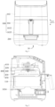
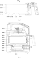
- the air fryer 10 comprises a machine 100, a smoke box 200 and a heating member 300.
- the air fryer 10 comprises the machine 100, the smoke box 200 and the heating member 300.
- the food materials are placed in the cooking cavity 110.
- the smoking materials in some embodiments, wood chips
- the smoke generated in the smoke box 200 can be discharged to the cooking cavity 110 to smoke the food materials in the cooking cavity 110, to increase the flavor of the food materials and enriching the functions of the air fryer 10, and thus, the air fryer 10 further has a smoking mode while also having conventional cooking modes (such as the air frying mode and the baking mode), and this can satisfy users' diversified use needs and thus improves the use performance and the market competitiveness of the product.
- the smoke box 200 communicates with the cooking cavity 110 through the overflowing portion 122, that is, the smoking materials in the smoke box 200 is carbonized due to high temperature and then gives off smoke, the smoke flows to the overflowing portion 122 of the oil receiving tray 120 and flows to the cooking cavity 110 through the overflowing portion 122. And, the overflowing portion 122 communicates with the smoke box 200, and the overflowing portion 122 communicates with the cooking cavity 110.
- the smoke box 200 is located between the oil receiving tray 120 and the heating member 300.
- the cooperating structure of the smoke box 200, the oil receiving tray 120 and the heating member 300 is further defined, and the smoke box 200 is located between the oil receiving tray 120 and the heating member 300. That is, compared with the heating member 300, the smoke box 200 is closer to the oil receiving tray 120.
- the heat generated when the heating member 300 works can be concentrated and conducted to the smoke box 200, and this helps improve the smoke discharging speed of the smoke box 200.
- the cooperating structure of the smoke box 200, the oil receiving tray 120 and the heating member 300 is further defined, and the heating member 300 is located at the peripheral side of the smoke box 200.
- the occupation rate of the inner space of the air fryer 10 in the height direction of the air fryer 10 can be reduced while the effectiveness and the feasibility of heating the smoke box 200 by the heating member 300 is ensured.
- the number of the heating member 300 is multiple, and the plurality of heating members 300 are arranged at intervals along the circumferential direction of the smoke box 200.
- the smoke box 200 is provided in the machine body 102.
- the carrier 104 is provided in the machine body 102, and the carrier 104 is provided with the cooking cavity 110 and the oil receiving tray 120.
- the hot air apparatus 400 is configured to supply hot air to the cooking cavity 110.
- the structure of the air fryer 10 is further defined, the machine 100 comprises the machine body 102 and the carrier 104, and the air fryer 10 further comprises the hot air apparatus 400.
- the carrier 104 is provided with the cooking cavity 110 and the oil receiving tray 120, and the food materials are placed in the cooking cavity 110 of the carrier 104. That is, the carrier 104 has both functions of carrying the food materials and carrying the oil of the food materials.
- the carrier 104 comprises a frying tray 1042 and a frying barrel 1044.
- the inner surface of the frying tray 1042 encloses the cooking cavity 110.
- the frying barrel 1044 is connected to the outer surface of the frying tray 1042, and at least a portion of the frying barrel 1044 forms the oil receiving tray 120.
- the structure of the carrier 104 is further defined, the carrier 104 comprises the frying tray 1042 and the frying barrel 1044, the frying barrel 1044is connected to the outer surface of the frying tray 1042, that is, the frying barrel 1044 is located at the outer side of the frying tray 1042.
- the inner surface of the frying tray 1042 encloses the cooking cavity 110. That is, the cooking cavity 110 has a double-layered wall surface structure formed by a double-layered housing.
- the frying barrel 1044 forms the oil receiving tray 120, the oil generated by cooking the food materials in the frying tray 1042 can be contained and received by the frying barrel 1044, and the smoke can further flow to the cooking cavity 110 of the frying tray 1042 through the frying barrel 1044.
- an overflowing cavity 1046 is enclosed by the outer surface of the frying tray 1042 and inner surface of the frying barrel 1044, and the overflowing cavity 1046 communicates with the overflowing portion 122.
- the structure of the carrier 104 is further defined, the overflowing cavity 1046 is enclosed by the outer surface of the frying tray 1042 and inner surface of the frying barrel 1044, and the overflowing cavity 1046 communicates with the overflowing portion 122. That is, the smoke generated in the working process of the smoke box 200 flows to the overflowing cavity 1046 through the overflowing portion 122, and then flows to the cooking cavity 110 through the overflowing cavity 1046.
- the overflowing cavity 1046 has a larger volume than the overflowing portion 122, and this helps increase the contact area between the smoke and the cooking cavity 110, and further helps improve the balance and the consistency of smoking the food materials at different positions inside the cooking cavity 110, and helps improve the smoked tastes of the food materials.
- the structure of the frying tray 1042 is further defined, the frying tray 1042 is provided with the baffle 1048 and the first overflowing port 1050, the overflowing portion 122 is disposed corresponding to the baffle 1048, and the first overflowing port 1050 is located at the peripheral side of the baffle 1048.
- the baffle 1048 is disposed corresponding to the overflowing portion 122, and thus, even if the oil flows to the baffle 1048, the baffle 1048 will change the flowing path of the oil, the oil will flow to the first overflowing port 1050 away from the overflowing portion 122 under the guiding of the baffle 1048 and will be received in the oil receiving tray 120. That is, the oil will not flow to the smoke box 200 through the overflowing portion 122.
- the first overflowing port 1050 has both functions of allowing the smoke to enter the cooking cavity 110 and allowing the oil to flow to the oil receiving tray 120.
- the structure of the oil receiving tray 120 is further defined, and a portion of the oil receiving tray 120 protrudes towards the direction of the cooking cavity 110 to form the protruding structure 124, and the protruding structure 124 is provided with the overflowing portion 122, i.e., the protruding structure 124 serves as the mounting carrier of the overflowing portion 122.
- the protruding structure 124 is provided with the overflowing portion 122, the portion of the oil receiving tray 120 located at the peripheral side of the protruding structure 124 is disposed corresponding to the first overflowing port 1050, that is, the height of the region of the oil receiving tray 120 used for containing and receiving the oil is smaller than the height of the overflowing portion 122.
- the overflowing cavity 1046 is enclosed by the outer surface of the frying tray 1042 and the inner surface of the frying barrel 1044, and thus, the smoke generated in the smoke box 200 flows to the overflowing cavity 1046 through the overflowing portion 122, and flows to the first overflowing port 1050 located at the peripheral side of the baffle 1048 through the overflowing cavity 1046, to flow to the top of the food materials from the bottom of the food materials through the first overflowing port 1050 and then thoroughly smoke the food materials, and thus, different positions of the food materials can be effectively smoked, and the balance and the consistency of the smoking effect can be ensured and the tastes of the food materials can be ensured.
- the frying tray 1042 is provided with a grid region, and a plurality of the first overflowing ports 1050 are formed in the grid region.
- the overflowing portion 122 is provided at the side of the protruding structure 124 facing the cooking cavity 110.
- At least one of the machine body 102 and the carrier 104 is provided with a smoke flow channel 106, and the smoke flow channel 106 communicates the overflowing portion 122 with the smoke box 200.
- the machine body 102 When the machine body 102 is provided with the smoke flow channel 106, the machine body 102 is used as the mounting carrier of the smoke flow channel 106, has the functions of mounting and fixing the smoke flow channel 106, and can ensure the cooperating dimensions of the smoke flow channel 106, the overflowing portion 122 and the smoke box 200.
- the carrier 104 When the carrier 104 is provided with the smoke flow channel 106, the carrier 104 is used as the mounting carrier of the smoke flow channel 106, has the functions of mounting and fixing the smoke flow channel 106, and can ensure the cooperating dimensions of the smoke flow channel 106, the overflowing portion 122 and the smoke box 200.
- the number of the smoke flow channel 106 is multiple, and the plurality of smoke flow channels 106 are arranged at intervals along the circumferential direction of the cooking cavity 110.
- the machine body 102 is provided with a sealing member 600, the sealing member 600 abuts the outer surface of the carrier 104, and the sealing member 600 is disposed surrounding the overflowing portion 122.
- the machine body 102 is provided with the sealing member 600, the sealing member 600 abuts the outer surface of the carrier 104, the sealing member 600 is configured to seal the connection portion between the machine body 102 and the carrier 104, and this prevents the occurrence of the circumstance that the smoke escapes from the connection portion between the machine body 102 and the carrier 104, and the smoke is directly guided to the overflowing portion 122.
- the sealing member 600 is disposed surrounding the overflowing portion 122, and thus can seal the connection portion between the machine body 102 and the carrier 104 from multiple directions and multiple angles, and can ensure the sealing performance of the smoke flow channel 106.
- the sealing member 600 is disposed surrounding the overflowing portion 122; however, in some other embodiments, the sealing member 600 is disposed surrounding the notch of the accommodating groove 240 of the smoke box 200.
- the sealing member 600 comprises a sealing ring, and the sealing ring is a rubber ring, a plastic ring, etc.
- the machine body 102 is further provided with a first passage 1022 and a first outlet 1024.
- the first passage 1022 communicates the cooking cavity 110 with the first outlet 1024.
- the structure of the machine body 102 is further defined, and the machine body 102 is further provided with the first passage 1022 and the first outlet 1024, the first passage 1022 communicates with the first outlet 1024, and the first passage 1022 communicates with the cooking cavity 110, and thus, the smoke in the cooking cavity 110 can flow to the first passage 1022, and is discharged out of the air fryer 10 through the first outlet 1024. That is, the first passage 1022 has the function of discharging the smoke. The use needs of the air fryer 10 can be satisfied.
- the first outlet 1024 is located above the cooking cavity 110.
- the first outlet 1024 is located at the side of the cooking cavity 110.
- the first outlet 1024 is located in the bottom of the cooking cavity 110.
- the hot air apparatus 400 comprises a motor 410, the machine body 102 is further provided with a second passage 1026 and a second outlet 1028.
- At least a portion of the motor 410 is located in the second passage 1026.
- the second passage 1026 and the first passage 1022 are arranged at an interval, and the second passage 1026 communicates with the second outlet 1028.
- the structure of the machine body 102 is further defined, and the machine body 102 is further provided with the second passage 1026 and the second outlet 1028, and the second passage 1026 communicates with the second outlet 1028.
- the hot air apparatus 400 comprises the motor 410, at least a portion of the motor 410is located in the second passage 1026, the airstream in the second passage 1026 will be discharged out of the air fryer 10 through the second outlet 1028, the flowing of the airstream will take the heat generated when the motor 410 works, to achieve the function of cooling the motor 410 and dissipating heat for the motor 410. That is, the second passage 1026 has the function of heat dissipation.
- the second passage 1026 and the first passage 1022 are arranged at an interval, that is, the first passage 1022 and the second passage 1026 are two relatively independent passages, the airstream in the first passage 1022 will not flow to the second passage 1026, and the airstream in the second passage 1026 will not flow to the first passage 1022.
- the arrangement can prevent the occurrence of the circumstance that the smoke in the first passage 1022 flows back to the second passage 1026, and meanwhile can prevent the hot air in the second passage 1026 from flowing back to the first passage 1022.
- the air fryer 10 further comprises: a circuit board, provided in the second passage 1026, and the circuit board is electrically connected to the hot air apparatus 400.
- the structure of the air fryer 10 is further defined, the air fryer 10 further comprises the circuit board, the circuit board is provided in the second passage 1026, and the circuit board is electrically connected to the hot air apparatus 400; the circuit board has the function of controlling the working of the hot air apparatus 400.
- the circuit board generates heat when it works, the circuit board is placed in the second passage 1026, the airstream in the second passage 1026 will be discharged out of the air fryer 10 through the second outlet 1028, the flowing of the airstream will take the heat generated when the circuit board works, and thus the function of cooling the circuit board and dissipating heat for the circuit board is achieved.
- the hot air apparatus 400 further comprises a drive shaft 420, a first fan blade 430, a second fan blade 440 and a heat generating member 450.
- the drive shaft 420 is connected to the motor 410, and the drive shaft 420 passes through the second passage 1026 and extends into the first passage 1022.
- the first fan blade 430 is located in the first passage 1022, and the first fan blade 430 is connected to the drive shaft 420.
- the second fan blade 440 is located in the second passage 1026, and the second fan blade 440 is connected to the drive shaft 420.
- the heat generating member 450 is provided in the first passage 1022.
- the hot air apparatus 400 further comprises the drive shaft 420, the first fan blade 430, the second fan blade 440 and the heat generating member 450.
- the drive shaft 420 is connected to the motor 410, the drive shaft 420 passes through the second passage 1026 and extends into the first passage 1022, and the drive shaft 420 is connected to the first fan blade 430.
- the motor 410 works and thus can drive the drive shaft 420 to rotate, the rotating of the drive shaft 420 can drive the first fan blade 430 to rotate, and the rotating of the first fan blade 430 can drive the hot air to circulate between the cooking cavity 110 and the first passage 1022.
- the drive shaft 420 is connected to the motor 410, and the drive shaft 420 is further connected to the second fan blade 440 which is located in the second passage 1026.
- the motor 410 works and thus can drive the drive shaft 420 to rotate, the rotating of the drive shaft 420 can drive the second fan blade 440 to rotate, and the rotating of the second fan blade 440 can drive the airstream in the second passage 1026 to flow to the second outlet 1028, to meet the use need of dissipating heat for the motor 410, and thus, the temperature rise of the motor 410 can be lowered, and this helps extend the service life of the motor 410.
- an air inlet is further provided in the machine body 102, and the air inlet communicates with the second passage 1026.
- the heat generating member 450 works to heat the airstream in the first passage 1022, and the hot air is generated therein.
- the heat generating member 450 comprises a heat generating tube, a heat generating sheet, a heat generating plate, etc., which will not be listed herein.
- both the first fan blade 430 and the second fan blade 440 are connected to the drive shaft 420, that is, the motor 410 can drive the first fan blade 430 and the second fan blade 440 to work at the same time, and thus, the use need on the working of the first fan blade 430 and the second fan blade 440 is ensured and the device input for driving the first fan blade 430 and the second fan blade 440 to work is further reduced, and thus the production cost of the air fryer 10is reduced.
- both the first fan blade 430 and the second fan blade 440 comprise: a deflector, and the deflector is connected to the drive shaft 420; a plurality of fan blades, and the plurality of fan blades are connected to the same side of the deflector, and the plurality of fan blades are arranged at intervals in the circumferential direction of the drive shaft 420; and, the deflector of the first fan blade 430 is disposed opposite to the deflector of the second fan blade 440.
- the first fan blade 430 and the second fan blade 440 are in a mirror arrangement which takes the plane perpendicular to the axial direction of the drive shaft 420 as a symmetry plane.
- the motor 410 drives the first fan blade 430 and the second fan blade 440 to move at the same time, the first fan blade 430 can drive the hot air to circulate between the first passage 1022 and the cooking cavity 110, and the second fan blade 440 can dissipate heat for the motor 410 and the circuit board.
- the machine body 102 comprises: a housing 1030, and the housing 1030 is provided with the first outlet 1024, the second outlet 1028, the first passage 1022 and the second passage 1026, the first passage 1022 communicates the cooking cavity 110 with the first outlet 1024, and the second passage 1026 communicates with the second outlet 1028; a partition plate 1031, provided in the housing 1030, and the partition plate 1031 comprises a first end surface and a second end surface which are disposed opposite to each other in the height direction of the machine body 102, the first end surface forms a portion of the wall surface of the first passage 1022, the second end surface forms a portion of the wall surface of the second passage 1026, and the partition plate 1031 is located between the first outlet 1024 and the second outlet 1028; and the hot air apparatus 400 comprises the motor 410, and at least a portion of the motor 410 is located in the second passage 1026.
- the structure of the machine body 102 is further detailed, the machine body 102 comprises the housing 1030 and the partition plate 1031, and the partition plate 1031 is provided in the housing 1030.
- the partition plate 1031 comprises the first end surface and the second end surface, the first end surface and second end surface are arranged at an interval and opposite to each other in the height direction of the machine body 102.
- the first end surface forms a portion of the wall surface of the first passage 1022
- the second end surface forms a portion of the wall surface of the second passage 1026. That is, the first passage 1022 and the second passage 1026 are located at the two opposite sides of the partition plate 1031.
- the partition plate 1031 is located between the first outlet 1024 and the second outlet 1028, that is, the partition plate 1031 has the function of partitioning the first outlet 1024 from the second outlet 1028, and this can effectively prevent the airstream discharged out of the first outlet 1024 from flowing into the second outlet 1028, and can further effectively prevent the airstream discharged out of the second outlet 1028 from flowing into the first outlet 1024.
- This arrangement can prevent the occurrence of the circumstance that the smoke in the first passage 1022 flows back to the second passage 1026, and can further prevent the hot air in the second passage 1026 from flowing back to the first passage 1022.
- the machine body 102 comprises a cavity 1033 with a first opening 1032, and the carrier 104 can be detachably provided in the cavity 1033 through the first opening 1032.
- the cooperating structure of the machine body 102 and the carrier 104 is further defined, the machine body 102 comprises the cavity 1033 with the first opening 1032, the carrier 104 is detachably provided in the cavity 1033 through the first opening 1032, that is, the carrier 104 can be inserted into the cavity 1033 through the first opening 1032 in the machine body 102 to seal the cavity 1033, and the carrier 104 can further be separated from the machine body 102 through the first opening 1032 in the machine body 102 to open the cavity 1033.
- the carrier 104 is provided with the cooking cavity 110 and the oil receiving tray 120, the cooking cavity 110 and the oil receiving tray 120 are further separated from the machine body 102 when the carrier 104 is separated from the machine body 102.
- a smoke cavity 1034 is enclosed by the carrier 104 and the wall of the cavity 1033, and the smoke box 200 is detachably connected to the smoke cavity 1034.
- the smoke cavity 1034 is enclosed by the carrier 104 and the wall of the cavity 1033, i.e., when the carrier 104 is inserted into the cavity 1033 through the first opening 1032, the smoke cavity 1034 for accommodating the smoke box 200 is enclosed between the carrier 104 and the wall of the cavity 1033.
- the smoke cavity 1034 has the function of mounting and fixing the smoke box 200.
- the smoke cavity 1034 is partitioned from the cavity 1033 by the carrier 104; when the carrier 104 is separated from the machine body 102 through the first opening 1032 in the machine body 102, the smoke box 200 is completely exposed in the cavity 1033, and at the point, users can disassemble and assemble the smoke box 200 through the first opening 1032, and can further put smoking materials in the smoke box 200 through the first opening 1032.
- the smoke box 200 is detachably connected to the smoke cavity 1034, i.e., the disassembling and assembling of the smoke box 200 and the mounting position of the smoke box 200 with respect to the smoke cavity 1034 can be determined according to actual circumstances, and this can adapt to the use needs on the air fryers 10 of different models, and thus achieves strong product adaptability and improves the service performance of the product.
- the smoke box 200 is detachably connected to the smoke cavity 1034, and this helps wash and clean the smoke box 200, and can ensure the sanitation and safety of the air fryer 10 in use.
- the carrier 104 when the smoking mode of the air fryer 10 is used, the carrier 104 can be separated from the machine body 102 through the first opening 1032 in the machine body 102, the smoking materials are put into the smoke box 200, and then, the carrier 104 is inserted into the cavity 1033 through the first opening 1032 in the machine body 102.
- the carrier 104 can be separated from the machine body 102 through the first opening 1032 in the machine body 102, then the smoke box 200 is taken out for cleaning.
- the smoke box 200 can be taken out of the machine body 102, to directly cook the food materials in the cooking cavity 110 and further achieve conventional cooking operations such air-frying and baking.
- the arrangement can satisfy diversified use needs, the functions of the product are enriched, the purpose of achieving multiple cooking functions can be achieved, and the use performance and the market competitiveness of the product are improved.
- connection method between the smoke box 200 and the machine body 102 comprises, but is not limited to, snapping, screwing, magnetic attaching and fastening connection through a fastener (in some embodiments, a screw, a bolt or a rivet).
- the machine body 102 is further provided with a second opening 1035, and the smoke box 200 is inserted into the smoke cavity 1034 through the second opening 1035.
- the structure of the machine body 102 is further defined, and the machine body 102 is further provided with the second opening 1035, the second opening1035 communicates with the smoke cavity 1034, the smoke box 200 can be inserted into the smoke cavity 1034 through the second opening 1035, and the smoke box 200 can further be drawn out from the smoke cavity 1034 through the second opening 1035.
- the smoke box 200 can be separated from the smoke cavity 1034 through the second opening 1035 to clean the smoke box 200 or put smoking materials in the smoke box 200.
- the smoke box 200 is provided with an accommodating groove 240, and the accommodating groove 240 communicates with the overflowing portion 122.
- the structure of the smoke box 200 is further defined, the smoke box 200 is provided with the accommodating groove 240, the smoking materials can be put into the accommodating groove 240, and can further be taken out of the accommodating groove 240.
- the accommodating groove 240 communicates with the overflowing portion 122, and the smoke flows to the overflowing portion 122 through the notch of the accommodating groove 240.
- the air fryer 10 further comprises a smoke cover 800.
- the smoke cover 800 is detachably connected to the smoke box 200.
- the smoke cover 800 is provided with a through hole 810, and the accommodating groove 240 communicates with the overflowing portion 122 via the through hole 810.
- the structure of the air fryer 10 is further defined, and the air fryer 10 further comprises the smoke cover 800, and the smoke cover 800 is detachably connected to the smoke box 200, i.e., the assembling and disassembling of the smoke cover 800 and the smoke box 200 and the mounting position of the smoke cover 800 with respect to the smoke box 200 can be determined according to actual circumstances, and this can further meet the use needs on the air fryers 10 of different models, and achieves strong product adaptability and improves the service performance of the product.
- the smoke cover 800 is provided with the through hole 810, the through hole 810 communicates with the accommodating groove 240, and the through hole 810 communicates with the overflowing portion 122, i.e., the accommodating groove 240 communicates with the overflowing portion122 via the through hole 810.
- the smoke in the accommodating groove 240 flows out of the smoke box 200 via the through hole 810, and then flows to the overflowing portion 122.
- the smoke cover 800 is arranged covering the smoke box 200, and thus the smoke cover 800 can prevent the scattering of the particles of the smoking materials in the smoke box 200, and the smoke box 200 cooperates with the smoke cover 800 to limit the smoking materials, to prevent the overflow of the smoking materials, especially when the smoke box 200 is drawn.
- the accommodating groove 240 of the air fryer 10 communicates with the external atmosphere.
- the accommodating groove 240 of the air fryer 10 through reasonably communicating the accommodating groove 240 of the air fryer 10 with the external atmosphere, i.e., the air in the environment can flow to the accommodating groove 240, and the gas flows to the overflowing portion 122 after passing through the smoking materials.
- the gas passes through the smoke box 200 and can contact the smoking materials thoroughly, and this helps burn the smoking materials and can burn the smoking materials thoroughly, and the smoke materials are burned completely. This helps improve the smoking efficiency of the smoking materials.
- the machine 100 is further provided with an entrance 130
- the smoke box 200 is provided with meshes 210
- the meshes 210 communicate the entrance 130 with the accommodating groove 240.
- the cooperating structure of the machine 100 and the smoke box 200 is further defined.
- the machine 100 is further provided with the entrance 130.
- the smoke box 200 is provided with meshes 210.
- the entrance 130 communicates with the meshes 210 of the smoke box 200, the meshes 210 communicate with the accommodating groove 240, and the accommodating groove 240 communicates with the overflowing portion 122.
- the gas in the environment can flow into the meshes 210 through the entrance 130, and then flow to the overflowing portion 122 after going through the smoking materials.
- the gas flows through the smoke box 200, and can contact the smoking materials thoroughly, and this helps the burning of the smoking materials and can burn the smoking materials thoroughly, and the smoke materials are burned completely. This helps improve the smoking efficiency of the smoking materials.
- the entrance 130, the meshes 210 and the accommodating groove 240 form an air passage, and the smoking materials can contact the air thoroughly.
- the portion of the machine body 102 located at the entrance 130 and the smoke box 200 is a flame retardant part, and this can reduce the probability of the occurrence of the burning of the machine body 102 at high temperature and helps improve the safety and reliability of the air fryer 10 in use.
- the notch of the accommodating groove 240 forms a second overflowing port 220, and the second overflowing port 220 communicates with the overflowing portion 122.
- the entrance 130 is located at the side of the smoke box 200 away from the overflowing portion 122.
- the arrangement position of the entrance 130 is further defined, and the entrance 130 is located at the side of the smoke box 200 away from the overflowing portion 122, and this arrangement makes the air flow to the overflowing portion 122 from the side of the smoke box 200 away from the overflowing portion 122, and extends the flowing path of the air in the accommodating groove 240, and thus makes the smoking materials contact the air thoroughly, and helps improve the burning rate of the smoking materials.
- grid placing boards 230 are provided in the accommodating groove 240, the grid placing boards 230 and the meshes 210 are arranged at intervals, and the aperture of the grid placing boards 230 is greater than the aperture of the meshes 210.
- the grid placing boards 230 are provided in the accommodating groove 240, and the smoking materials are placed on the grid placing boards 230.
- the gas can flow to the bottom of the smoking materials through the grid placing boards 230, and then flow to the top of the smoking materials, to thoroughly heat the smoking materials. This helps burn the smoking materials thoroughly.
- the grid placing boards 230 and the meshes 210 are arranged at intervals, i.e., there are gaps between the grid placing boards 230 and the meshes 210, and this helps the gas flow to the smoking materials at different positions on the grid placing boards 230, and helps burn the smoking materials, and thus the smoking materials can be heated thoroughly.
- the aperture of the grid placing boards 230 is arranged to be greater than the aperture of the meshes 210, the meshes 210 have the function of carrying the ashes, to lower the occurrence of the circumstance that the ashes drop out of the air fryer 10 through the entrance 130.
- the grid placing boards 230 are provided in the accommodating groove 240, the grid placing boards 230 and the meshes 210 are arranged at intervals, and the aperture of the grid placing boards 230 is smaller than the aperture of the meshes 210.
- the grid placing boards 230 are provided in the accommodating groove 240, and the smoking materials are placed on the grid placing boards 230.
- gas can flow to the bottom of the smoking materials through the grid placing boards 230, and then flow to the top of the smoking materials, to thoroughly heat the smoking materials. This helps burn the smoking materials thoroughly.
- the grid placing boards 230 and the meshes 210 are arranged at intervals, i.e., there are gaps between the grid placing boards 230 and the meshes 210, and this helps the gas flow to the smoking materials at different positions on the grid placing boards 230, and helps burn the smoking materials, and thus the smoking materials can be heated thoroughly.
- the aperture of the grid placing board 230 is smaller than the aperture of the meshes 210, i.e., compared with the aperture of the meshes 210, the aperture of the grid placing board 230 is smaller. Since the aperture of the grid placing board 230 is smaller, the grid placing board 230 can carry both the smoking materials and the ashes after the burning of the smoking materials.
- the meshes 210 are greater, and it helps pass the gas, and the gas can contact the smoking materials thoroughly.
- the side wall of the smoke box 200 is provided with the meshes 210, and in the height direction, the accommodating groove 240 is located under the meshes 210.
- the structure of the smoke box 200 is further defined, and the side wall of the smoke box 200 is provided with the meshes 210, and thus, the gas in the environment can flow to the accommodating groove through the meshes 210, and the gas flows to the overflowing portion 122 after passing through the smoking materials.
- the gas passes through the smoke box 200, and can contact the smoking materials thoroughly, and this helps the burning of the smoking materials and can burn the smoking materials thoroughly, and the smoking materials are burned completely. This helps improve the smoking efficiency of the smoking materials.
- the side wall of the smoke box 200 is provided with the meshes 210, the modification to the smoke box 200 is reduced while the effective contact of the air with the smoking materials is ensured, and this helps reduce the modification cost.
- the accommodating groove 240 is located under the meshes 210, and thus, the ashes of the smoking materials after burning will not flow out of the smoke box through the meshes 210.
- connection portion between the inner side wall 1100 of the frying barrel and the inner bottom wall 1000 of the frying barrel is provided with a protruding portion 900, the protruding portion 900 extends towards the direction of the cooking cavity 110, and the overflowing portion 122 is provided in the protruding portion 900; the overflowing portion 122 faces the side gap of the frying tray 1042 and the frying barrel 1044, or the overflowing portion 122 faces the oil leakage-free hole of the frying tray 1042.
- the structure of the frying barrel 1044 is reasonably disposed, and the connection portion between the inner side wall 1100 of the frying barrel and the inner bottom wall 1000 of the frying barrel is provided with the protruding portion 900, and the protruding portion 900 is provided with the overflowing portion 122, i.e., the protruding portion 900 is used as the mounting carrier of the overflowing portion 122.
- the overflowing portion 122 is arranged facing the side gap of the frying barrel 1044 and the frying tray 1042, or the overflowing portion 122 faces the oil leakage-free hole in the bottom wall of the frying tray 1042.
- the protruding portion 900 extends towards the direction of the cooking cavity 110, and thus, only when the accumulated oil is higher than the position of the overflowing portion 122, the oilcan flow to the overflowing portion 122.
- the arrangement can have the function of blocking the oil from flowing to the smoke box 200through the overflowing portion 122, and prevent polluting the smoking materials in the smoke box 200, and can prevent the generation of the oily smoke.
- portion of the frying barrel 1044 at the peripheral side of the protruding portion 900 can store a certain amount of oil.
- the protruding portion 900 and the frying tray 1042 are arranged at an interval, or the protruding portion 900 abuts the frying tray 1042.
- a portion of the gas can flow to the cooking cavity 110 through the gap between the protruding portion 900 and the frying tray 1042.
- the protruding portion 900 when the protruding portion 900 abuts the frying tray 1042, the protruding portion 900 has the function of supporting and fixing the frying tray 1042, to ensure the position relation between the frying tray 1042 and the frying barrel 1044. And, since the protruding portion 900 is disposed, the position relation between the frying tray 1042 and the frying barrel 1044 can be limited only by the protruding portion 900.
- a connecting portion can further be disposed, and the connection portion connects the frying barrel 1044 and the frying tray 1042, i.e., the connecting portion cooperates with the protruding portion 900 to limit the position relation between the frying tray 1042 and the frying barrel 1044.
- the overflowing portion 122 goes through the top portion of the protruding portion 900, or goes through the side portion of the protruding portion 900, that is, the smoke can enter the cooking cavity 110 through the bottom portion or the side portion of the frying tray 1042.
- the inner bottom wall 1000 of the frying barrel is provided with a plate body 1200, the plate body 1200 extends towards the direction of the cooking cavity 110, the overflowing portion is provided between the plate body 1200 and the inner side wall of the frying barrel 1044; the overflowing portion faces the side gap of the frying tray and the frying barrel, or the overflowing portion faces the oil leakage-free hole of the frying tray.
- the overflowing portion 122 is arranged facing the side gap of the frying barrel 1044 and the frying tray 1042, or the overflowing portion 122 faces the oil leakage-free hole in the bottom wall of the frying tray 1042.
- the frying tray 1042 is provided with a third overflowing port 1300, the plate body 1200 is located between the third overflowing port 1300 and the overflowing portion 122, and the third overflowing port 1300 communicates the overflowing portion 122 with the cooking cavity 110.
- the structure of the frying barrel 1044 is reasonably disposed, and the inner bottom wall 1000 of the frying barrel is provided with the plate body 1200, and the plate body 1200 is located between the third overflowing port 1300 and the overflowing portion 122.
- the plate body 1200 extends towards the direction of the cooking cavity 110, and the plate body 1200 is located between the third overflowing port 1300 and the overflowing portion 122, and thus, only when the accumulated oil is higher than the position of the plate body 1200, the oilcan flow to the overflowing portion 122.
- the arrangement can have the function of blocking the oil from flowing to the smoke box 200 through the overflowing portion 122, and prevent polluting the smoking materials in the smoke box 200, and can prevent the generation of the oily smoke.
- portion of the frying barrel 1044 at the peripheral side of the plate body 1200 can store a certain amount of oil.
- the plate body 1200 and the frying tray 1042 are arranged at an interval, or the plate body 1200 abuts the frying tray 1042.
- a portion of the gas can flow to the cooking cavity 110 through the gap between the plate body 1200 and the frying tray 1042 and through the bottom wall or the side wall of the frying tray 1042.
- the plate body 1200 when the plate body 1200 abuts the frying tray 1042, the plate body 1200 has the function of supporting and fixing the frying tray 1042, to ensure the position relation between the frying tray 1042 and the frying barrel 1044. At the point, the gas enters the cooking cavity 110 via the side wall of the frying tray 1042. And, since the plate body 1200 is disposed, the position relation between the frying tray 1042 and the frying barrel 1044 can be limited only by the plate body 1200.
- a connecting portion can further be disposed, and the connection portion connects the frying barrel 1044 and the frying tray 1042, i.e., the connecting portion cooperates with the plate body 1200 to limit the position relation between the frying tray 1042 and the frying barrel 1044.
- the plate body 1200 can be one piece, and the plate body 1200 and the inner wall of the frying barrel 1044 are enclosed tightly.
- the plate body 1200 can be a ring, and is arranged in an enclosing manner along the circumferential direction of the cooking cavity 110.
- the heating member 300 is further configured to supply heat to the cooking cavity 110.
- the heating member 300 is further configured to supply heat to the cooking cavity 110, i.e., the heating member 300 can work for the cooking cavity 110 and the smoke box 200, and the heating member 300 has the function of assisting heating the cooking cavity 100.
- the arrangement enriches the functions of the heating member 300.
- the machine 100 is further provided with a guiding device 140, the guiding device 140 is located inside the smoke cavity 1034, and the smoke box 200 and the guiding device 140 are in sliding connection.
- the machine 100 is further provided with the guiding device 140, the guiding device 140 is located inside the smoke cavity 1034, the smoke cavity 1034 is used as a mounting carrier of the guiding device 140, and has the function of mounting and fixing the guiding device 140.
- the smoke box 200 and the guiding device 140 are in sliding connection, the guiding device 140 has the function of liming the moving path of the smoke box 200, and the smoke box 200 can slide into the smoke cavity 1034 along the guiding device 140, or slide out of the smoke cavity 1034 along the guiding device 140.
- the arrangement can achieve the sliding connection between the smoke box 200 and the machine 100, and helps users withdraw the smoke box 200 with respect to the machine 100, and helps users disassemble and assemble the smoke box 200.
- the guiding device 140 is provided with a slideway 142 and an avoidance port 144, the smoke box 200 and the slideway 142 are in sliding connection, and the slideway 142 encapsulates the outer edge of the smoke box 200; and the smoke box 200 communicates with the smoke cavity 1034 through the avoidance port 144.
- the structure of the guiding device 140 is further defined, and the guiding device 140 is provided with the sideway 142 and the avoidance port 144.
- the slideway 142 and the smoke box 200 are in sliding connection, in an embodiment, the outer edge of the smoke box 200 is in sliding connection with the slideway 142.
- the slideway 142 cooperates with the outer edge of the smoke box 200, and the smoke box 200 can slide along the slideway 142.
- the slideway 142 encapsulates the outer edge of the smoke box 200, and this arrangement ensures the effectiveness and feasibility of the sliding connection between the slideway 142 and the outer edge of the smoke box 200, and meanwhile increases the contact area and contact angle between the slideway 142 and the smoke box 200, improves the stability and the reliability of the assembling of the smoke box 200 and the guiding device 140, and the circumstance that the smoke box 200 is arranged obliquely will not appear.
- the guiding device 140 is provided with the avoidance port 144, the avoidance port 144 is configured to avoid the smoke box 200, and this can meet the use need on communicating the smoke box 200 with the smoke cavity 1034, and provides effective and reliable structural support for the communication between the smoke box 200 and the overflowing portion 122.
- the guiding device 140 extends along the direction perpendicular to the height direction of the machine 100.
- the extending direction of the guiding device 140 is further defined, the guiding device 140 extends along the direction perpendicular to the height direction of the machine 100, i.e., withdrawing the smoke box 200 along the horizontal direction, or pushing back the smoke box 200 along the horizontal direction.
- the smoke box 200 can move and can be taken out and put back.
- the smoke box 200 is provided with a handle 250, and the handle 250 protrudes out of the outer surface of the machine 100 through the second opening 1035.
- the structure of the smoke box 200 is further defined, the smoke box 200 is provided with the handle 250, and the handle 250 protrudes out of the outer surface of the machine 100 through the second opening 1035. That is, when the smoke box 200 is assembled in place, the handle 250 on the smoke box 200 will expose out of the outer surface of the machine 100. The disassembling and the assembling of the smoke box 200 can be achieved easily by holding the handle 250.
- the arrangement helps reduce the difficulty for disassembling and assembling the smoke box 200, and further helps improve efficiency of disassembling and assembling the smoke box 200.
- the smoke box 200 further comprises a heat-insulating plate 260, and the heat-insulating plate 260 is located at one side of the handle 250.
- the structure of the smoke box 200 is further defined, and the smoke box 200 further comprises the heat-insulating plate 260, and the heat-insulating plate 260 is located at one side of the handle 250.
- the heat-insulating plate 260 is located at the inner side of the handle 250, that is, the portion of the smoke box 200 located in the machine 100 forms the heat-insulating plate 260, the heat-insulating plate 260 has the function of insulating heat, to reduce the heat transmitted to the handle 250, and thus, the users will not be burned when holding the handle 250.
- the smoke box 200 is provided with the accommodating groove 240, the accommodating groove240 has the function of accommodating the smoking materials, and the heat-insulating plate 260 is located between the accommodating groove 240 and the handle 250.
- the smoke cover 800 is further provided with a stiffening rib 820 and a vented zone 830, the stiffening rib 820 is located at one side of the vented zone 830, and the vented zone 830 is provided with a through hole 810.
- the structure of the smoke cover 800 is further defined, and the smoke cover 800 is further provided with the stiffening rib 820 and the vented zone 830, the stiffening rib 820 has the function of increasing the strength of the smoke cover 800, and reducing the occurrence of breaking or even damaging the smoke cover 800.
- stiffening rib 820 is located at one side of the vented zone 830, and the vented zone 830 is provided with the through hole 810, i.e., the stiffening rib 820 can avoid the arrangement of the vented zone 830, and will not block the smoke from flowing into the overflowing portion 122.
- the number of the stiffening rib 820 is at least one, and the number of the vented zone 830 is at least one.
- both the numbers of the stiffening rib 820 and the vented zone 830 are multiple, and one vented zone 830 is provided between two adjacent stiffening ribs 820.
- the smoke box 200 is located at the side wall of the machine body 102.
- the smoke box 200 is located at the side wall of the machine body 102, i.e., the smoke box 200 is close to the side wall of the machine body 102, that is, the distance between the smoke box 200 and the side wall of the machine body 102 is relatively small, and thus, the distance for putting the smoking materials to the smoke box 200 can be shortened, and this helps put the smoking materials in the smoke box 200 and further helps clean the smoke box 200, and has the advantage of convenient operation.
- the side wall of the machine body 102 is provided with the first opening 1032 and the second opening 1035.
- the positions of the first opening 1032 and the second opening 1035 are further defined, the side wall of the machine body 102 is provided with the first opening 1032 and the second opening 1035, i.e., a carrier 104 is inserted or withdrawn via the side wall of the machine body 102, and the smoke box 200 is inserted or withdrawn from the side wall of the machine body 102.
- the arrangement has the advantage of convenient operation.
- the cavity walls of the cooking cavity 110 comprise a barrier wall 112 and an overflowing wall 114
- the overflowing wall 114 is connected to the side of the barrier wall 112 away from the first opening 1032
- the barrier wall 112 and the overflowing portion 122 face each other and are arranged at an interval.
- the structure of the cavity walls of the cooking cavity 110 is further defined, and the cavity walls of the cooking cavity 110 comprise the barrier wall 112 and the overflowing wall 114, and the barrier wall 112 and the overflowing portion 122 face each other and are arranged at an interval, and the overflowing wall 114 is connected to the side of the barrier wall 112 away from the first opening 1032.
- the overflowing portion 122, the barrier wall 112 and the overflowing wall 114 cooperate with one another to change the flowing path of the smoke.
- the smoke generated in the smoke box 200 flows to the barrier wall 112 through the overflowing portion 122, the barrier wall 112 will block the smoke from continuously flowing along the current direction, the smoke will make a turn and flow to the overflowing wall 114 at the peripheral side of the barrier wall 112 along the barrier wall 112, and then flows to the cooking cavity 110 of the overflowing wall 114.
- the food materials when the food materials are cooked, the food materials can generate oil, the oil flows to the overflowing wall 114 along the food materials, and flow to the oil receiving tray 120 through the overflowing wall 114, that is, the oil receiving tray 120 has the function of carrying the oil of the food materials. Since the barrier wall 112and the overflowing portion 122 are opposite to each other and are disposed at an interval, the barrier wall 112 has the function of blocking the oil from flowing to the overflowing portion 122, to prevent the occurrence of the circumstance that the oil enters the smoke box 200 through the overflowing portion 122. If the oil flows to the smoke box 200 through the overflowing portion 122, the oil will generate oily smoke in a high temperature environment, and this will affect the tastes of the food materials and cause pollution to the environment.
- the barrier wall 112 and the overflowing portion 122 are disposed corresponding to each other and are disposed at an interval, and thus, even if the oil flows to the barrier wall 112, the barrier wall 112 will change the flowing path of the oil, the oil will flow to the overflowing wall 114 away from the overflowing portion 122 under the guiding of the barrier wall 112 and will be received in the oil receiving tray 120. That is, the oil will not flow to the smoke box 200 through the overflowing portion 122.
- the overflowing wall 114 has both functions of allowing the smoke to enter the cooking cavity 110 and allowing the oil to flow to the oil receiving tray 120.
- barrier wall 112 and the overflowing portion 122 face each other and are arranged at interval, i.e., there is a gap between the barrier wall 112 and the overflowing portion 122, and this provides a flowing space for the smoke to flow along the barrier wall 112 to the overflowing wall 114, and the smoke can smoothly flow to the overflowing wall 114.
- the smoke box 200 forms a first central line L1 along the horizontal direction
- the carrier 104 forms a second central line L2 along the horizontal direction
- the first central line L1 is at the right side of the second central line L2. That is, the smoke box 200 is arranged close to the side wall of the machine.
- the top wall of the machine body 102 is provided with the first opening 1032, and the side wall of the machine body 102 is provided with the second opening 1035.
- the positions of the first opening 1032 and the second opening 1035 are further defined, the top wall of the machine body 102 is provided with the first opening 1032, and the side wall of the machine body 102 is provided with the second opening 1035, i.e., the carrier 104 is inserted or withdrawn via the top wall of the machine body 102, and the smoke box 200 is inserted or withdrawn from the side wall of the machine body 102.
- the arrangement has the advantage of convenient operation.
- the machine body 102 is provided with a flip cover, the flip cover is provided covering the first opening 1032.
- the flip cover is opened, the first opening 1032 is exposed, and then the carrier 104 can be inserted or withdrawn through the first opening 1032.
- Fig. 3 Fig. 4 , Fig. 8 , Fig. 11, Fig. 12 and Fig. 13 indicate the flowing directions of the gas.
- one smoke cavity 1034 is added under the cooking cavity 110, and the particles of the wood chips are placed in the smoke box 200; the smoke box 200 is heated by the heating member 300 to a certain temperature, the particles of the wood chips generate smoke under the effect of high temperature, the generated smoke enters into the cooking cavity 110 through the smoke flow channel 106 between the smoke cavity 1034 and the cooking cavity 110 to smoke foods to increase the tastes of the foods.
- the air fryer 10 comprises the cooking cavity 110 and the smoke cavity 1034, the air fryer 10 further comprises the hot air apparatus 400, and the hot air apparatus 400 comprises the fan blade and a heating device.
- the air fryer 10 further comprises the heating member 300, and the heating member 300 is provided in the smoke cavity 1034.
- the smoke box 200 is used for placing the particles of the wood chips, the cooking cavity 110 and the smoke cavity 1034 present an upper and lower position relationship, and the cooking cavity 110 communicates with the smoke cavity 1034 through the smoke flow channel 106.
- the heating member 300 is under the smoke box 200. As shown in Fig. 4 , the heating member 300 can further surround the side wall of the smoke box 200.
- the bottom portion of the cooking cavity 110 is provided with the oil receiving tray 120.
- a portion of the oil receiving tray 120 protrudes towards the direction of the cooking cavity 110 to form the protruding structure 124, the protruding structure 124 is provided with the overflowing portion 122, and the overflowing portion 122 communicates with the smoke flow channel 106.
- the smoke generated in the smoke cavity 1034 enters the cooking cavity 110 from the overflowing portion 122, to smoke foods.
- the smoke box 200 can move and be taken out.
- the smoke box 200 can further slide out or can be put back horizontally along the guiding device 140.
- the smoke cover 800 is provided on the smoke box 200, and the through hole 810 is provided in the smoke cover 800 to allow the smoke to pass through.
- the filter 500 is provided in the smoke flow channel 106.
- the partition plate 1031 is provided between the first outlet 1024 and the second outlet 1028.
- an air passage can be provided in the smoke cavity 1034, and, the entrance 130, the meshes 210 and the accommodating groove 240 form the air passage.
- the smoke cavity 1034 can further be provided at the side wall of the machine body 102.
- the enclosing panel 1500 is provided in the smoke box 200, the accommodating groove 240 is formed by the enclosing of the enclosing panel 1500, the bottom wall of the smoke box 200 is provided with the meshes 210, and the meshes 210 are located at the peripheral side of the accommodating groove 240, and the height of the side wall of the smoke box 200 is larger than the height of the enclosing panel 1500.
- the structure of the smoke box 200 is further defined, and the enclosing panel 1500 is provided in the smoke box 200, the accommodating groove 240 is formed by the enclosing of the enclosing panel 1500, and the accommodating groove 240 is used for accommodating the smoking materials.
- the meshes 210 are located at the peripheral side of the accommodating groove 240, and gas in the environment can enter the accommodating groove 240 through the meshes 210. The gas flows through the accommodating groove 240 and can contact the smoking materials thoroughly, and this helps the burning of the smoking materials and can burn the smoking materials thoroughly, and the smoking materials are burned completely. This helps improve the smoking efficiency of the smoking materials.
- the height of the side wall of the smoke box 200 is larger than the height of the enclosing panel 1500, and this helps the air flow into the accommodating groove 240.
- the arrows shown in Fig. 16, Fig. 17 , Fig. 18 and Fig. 19 indicate the flowing directions of the airflow.
Landscapes
- Engineering & Computer Science (AREA)
- Food Science & Technology (AREA)
- Life Sciences & Earth Sciences (AREA)
- Wood Science & Technology (AREA)
- Zoology (AREA)
- Chemical & Material Sciences (AREA)
- Polymers & Plastics (AREA)
- Frying-Pans Or Fryers (AREA)
Abstract
Description
- The present disclosure relates to the field of air fryers, and particularly relates to an air fryer.
- In the related art, an air fryer does not have a smoking function, users usually use other cooking utensils to smoke foods after they heat the foods with the air fryer, and thus the operation is complicated.
- The present disclosure aims to solve at least one of the problems that exist in the prior art or related art.
- Thus, an aspect of the present disclosure proposes an air fryer.
- In view of this, an aspect according to the present disclosure proposes an air fryer, comprising: a machine, provided with a cooking cavity and an oil receiving tray, and the oil receiving tray is located at one side of the cooking cavity, and the oil receiving tray is provided with an overflowing portion; a smoke box, provided in the machine, and the smoke box communicates with the cooking cavity through the overflowing portion; and a heating member, provided in the machine, and the heating member is at least configured to supply heat to the smoke box.
- The air fryer provided by the present disclosure comprises the machine, the smoke box and the heating member.
- The machine is provided with the cooking cavity and the oil receiving tray, the oil receiving tray is provided with the overflowing portion, and the smoke box communicates with the cooking cavity through the overflowing portion.
- In an embodiment, food materials are placed in the cooking cavity and cooked in the cooking cavity, to meet use needs such as air-frying, heating and baking food materials.
- And, the smoke box communicates with the cooking cavity through the overflowing portion of the oil receiving tray, the heating member heats the smoke box, the smoking materials in the smoke box are carbonized due to high temperature and give off smoke, and the smoke can flow to the cooking cavity to smoke the food materials.
- In an embodiment, the food materials are placed in the cooking cavity. The smoking materials (in some embodiments, wood chips) are placed in the smoke box. After the food materials are baked, or in the process of baking the food materials, the smoke generated in the smoke box can be discharged to the cooking cavity to smoke the food materials in the cooking cavity, to increase the flavor of the food materials and enriching the functions of the air fryer, and thus, the air fryer further has a smoking mode while also having conventional cooking modes (such as the air frying mode and the baking mode), and this can satisfy users' various use needs and thus improves the use performance and the market competitiveness of the product.
- It can be understood that the food materials will generate oil when placed in the cooking cavity for cooking, the oil flows to the oil receiving tray along the food materials, that is, the oil receiving tray has the function of carrying the oil of the food materials, and decreases or even prevents the oil from flowing to the smoke box from the cooking cavity, and thus can lower the pollution to the smoking materials in the smoke box, and lowers the possibility of generating oily smoke by the oil in a high temperature environment.
- The smoking materials are placed in the smoke box, the carbonization of the smoking materials needs a temperature between 260°C and 400°C, and thus the cooking cavity and the smoke box are two relatively independent structures, the oil receiving tray has the function of containing and receiving the oil, and the oil generated by the cooking materials are separated from the smoke box, and this can prevent that the oil enters the smoke box, and then is decomposed and gives off smoke in a high temperature environment, and further affects user experience and the tastes of foods. In addition, as the weight of the smoking materials is relatively low, the oil receiving tray is configured to separate the smoking materials from the cooking cavity, to prevent the circulation air in the cooking cavity from blowing the smoking materials away. The arrangement enriches the functions of the oil receiving tray, and thus the oil receiving tray has both functions of carrying the oil of foods and guiding the smoke to the cooking cavity.
- It can be understood that the smoke box communicates with the cooking cavity through the overflowing portion, that is, the smoking materials in the smoke box are carbonized due to high temperature and then give off smoke, the smoke flows to the overflowing portion of the oil receiving tray and flows to the cooking cavity through the overflowing portion. And, the overflowing portion communicates with the smoke box, and the overflowing portion communicates with the cooking cavity.
- The above air fryer according to the present disclosure can further comprise the following additional features:
- in the above embodiment, furthermore, the oil receiving tray is located between the cooking cavity and the smoke box.
- In the embodiment, the relative positions of the oil receiving tray, the cooking cavity and the smoke box are further defined, and the oil receiving tray is located between the cooking cavity and the smoke box, that is, the oil receiving tray separates the cooking cavity from the smoke box, the oil receiving tray has the function of containing and receiving the oil, and the oil generated by the cooking materials is separated from the smoke box, and this can prevent that the oil enters into the smoke box and then is decomposed and gives off smoke in a high temperature environment, and further affects user experience and the tastes of foods. In addition, as the weight of the smoking materials is relatively low, the oil receiving tray is configured to separate the smoking materials from the cooking cavity, to prevent the circulation air in the cooking cavity from blowing the smoking materials away. Meanwhile, the overflowing portion of the oil receiving tray can further satisfy the use need of communicating the smoke box with the cooking cavity. The arrangement reuses the structure of the oil receiving tray, and reduces the device input for guiding the smoke while ensuring the effectiveness and feasibility of carrying the oil of foods and guiding the smoke to the cooking cavity, and helps reduce the production costs of products.
- In any of the above embodiments, furthermore, the heating member and the smoke box are located at the same side of the oil receiving tray.
- In the embodiment, the cooperating structure of the heating member, the smoke box and the oil receiving tray is further defined, and the heating member and the smoke box are located at the same side of the oil receiving tray, that is, the oil receiving tray separates the cooking cavity from the heating member and the smoke box, the oil receiving tray has the function of containing and receiving the oil, and the oil generated by the cooking materials is separated from the smoke box and the heating member. Thus, the circumstances are prevented that the oil drops to the heating member and then pollutes and damages the heating member, and the oil is decomposed and gives off smoke in a high temperature environment, and this helps improve the safety and reliability of the air fryer in use.
- In any of the above embodiments, furthermore, the smoke box is located between the oil receiving tray and the heating member.
- In the embodiment, the cooperating structure of the smoke box, the oil receiving tray and the heating member is further defined, and the smoke box is located between the oil receiving tray and the heating member. That is, compared with the heating member, the smoke box is closer to the oil receiving tray. Thus, the heat generated when the heating member works can be concentrated and conducted to the smoke box, and this helps improve the smoke discharging speed of the smoke box.
- In any of the above embodiments, furthermore, the heating member is located at the peripheral side of the smoke box.
- In the embodiment, the cooperating structure of the smoke box, the oil receiving tray and the heating member is further defined, and the heating member is located at the peripheral side of the smoke box. Thus, the occupation rate of the inner space of the air fryer in the height direction of the air fryer can be reduced while the effectiveness and the feasibility of heating the smoke box by the heating member is ensured.
- In any of the above embodiments, furthermore, the machine comprises: a machine body, and the smoke box is provided in the machine body; a carrier, provided in the machine body, and the carrier is provided with the cooking cavity and the oil receiving tray; and the air fryer further comprises a hot air apparatus for supplying hot air to the cooking cavity.
- In the embodiment, the structure of the air fryer is further defined, the machine comprises the machine body and the carrier, and the air fryer further comprises the hot air apparatus.
- The carrier is provided with the cooking cavity and the oil receiving tray, and the food materials are placed in the cooking cavity of the carrier. That is, the carrier has both functions of carrying the food materials and carrying the oil of the food materials.
- The hot air apparatus communicates with the cooking cavity, the hot air apparatus works and then can heat the air, to form the hot air, the hot air circulates and flows in the cooking cavity under the effect of the fan of the hot air apparatus to heat the food materials.
- In any of the above embodiments, furthermore, the carrier comprises: a frying tray, and the inner surface of the frying tray encloses the cooking cavity; and a frying barrel, connected to the outer surface of the frying tray, and at least a portion of the frying barrel forms the oil receiving tray.
- In the embodiment, the structure of the carrier is further defined, the carrier comprises the frying tray and the frying barrel, the frying barrel is connected to the outer surface of the frying tray, that is, the frying barrel is located at the outer side of the frying tray. In addition, the inner surface of the frying tray encloses the cooking cavity. That is, the cooking cavity has a double-layered wall surface structure formed by a double-layered housing. It can be understood that at least a portion of the frying barrel forms the oil receiving tray, the oil generated by cooking the food materials in the frying tray can be contained and received by the frying barrel, and the smoke can further flow to the cooking cavity of the frying tray through the frying barrel.
- In any of the above embodiments, furthermore, an overflowing cavity is enclosed by the outer surface of the frying tray and inner surface of the frying barrel, and the overflowing cavity communicates with the overflowing portion.
- In the embodiment, the structure of the carrier is further defined, the overflowing cavity is enclosed by the outer surface of the frying tray and inner surface of the frying barrel, and the overflowing cavity communicates with the overflowing portion. That is, the smoke generated in the working process of the smoke box flows to the overflowing cavity through the overflowing portion, and then flows to the cooking cavity through the overflowing cavity.
- The overflowing cavity has a larger volume than the overflowing portion, and this helps increase the contact area between the smoke and the cooking cavity, and further helps improve the balance and the consistency of smoking the food materials at different positions inside the cooking cavity, and helps improve the smoking tastes of the food materials.
- In any of the above embodiments, furthermore, the frying tray is provided with a baffle and a first overflowing port, the first overflowing port is located at the peripheral side of the baffle, and the overflowing portion is disposed corresponding to the baffle.
- In the embodiment, the structure of the frying tray is further defined, the frying tray is provided with the baffle and the first overflowing port, the overflowing portion is disposed corresponding to the baffle, and the first overflowing port is located at the peripheral side of the baffle.
- The baffle, the first overflowing port and the overflowing portion cooperate with each other to change the flowing path of the smoke.
- In an embodiment, the smoke generated in the smoke box flows to the baffle through the overflowing portion, the baffle can block the smoke from flowing along the current direction, the smoke will make a turn and flows to the first overflowing port at the peripheral side of the baffle along the baffle, and flows to the cooking cavity through the first overflowing port.
- In addition, when the food materials are cooked, the food materials can generate the oil, the oil flows to the first overflowing port along the food materials, and flows to the oil receiving tray through the first overflowing port, that is, the oil receiving tray has the function of carrying the oil of the food materials. Since the baffle is disposed corresponding to the overflowing portion, the baffle has the function of blocking the oil from flowing to the overflowing portion, to prevent the occurrence of the circumstance that the oil enters the smoke box through the overflowing portion. If the oil flows to the smoke box through the overflowing portion, the oil will generate oily smoke in a high temperature environment, and this will affect the tastes of the food materials and cause pollution to the environment.
- It can be understood that the baffle is disposed corresponding to the overflowing portion, and thus, even if the oil flows to the baffle, the baffle will change the flowing path of the oil, the oil will flow to the first overflowing port away from the overflowing portion under the guiding of the baffle and will be received in the oil receiving tray. That is, the oil will not flow to the smoke box through the overflowing portion.
- That is, the first overflowing port has both functions of allowing the smoke to enter the cooking cavity and allowing the oil to flow to the oil receiving tray.
- In any of the above embodiments, furthermore, a portion of the oil receiving tray protrudes towards the direction of the cooking cavity to form a protruding structure, the protruding structure is provided with the overflowing portion, and the portion of the oil receiving tray located at the peripheral side of the protruding structure is disposed corresponding to the first overflowing port.
- In the embodiment, the structure of the oil receiving tray is further defined, and a portion of the oil receiving tray protrudes towards the direction of the cooking cavity to form the protruding structure, and the protruding structure is provided with the overflowing portion, i.e., the protruding structure serves as the mounting carrier of the overflowing portion.
- Since the portion of the oil receiving tray located at the peripheral side of the protruding structure is disposed corresponding to the first overflowing port, the overflowing portion should be higher than the portion of the oil receiving tray located at the peripheral side of the protruding structure, that is, only when the accumulated oil is higher than the position of the overflowing portion, the oilcan flow to the overflowing portion. In other words, the arrangement can prevent the occurrence of the circumstance that the oil flows to the smoke box through the overflowing portion, and prevent polluting the smoking materials in the smoke box, and can prevent the generation of the oily smoke.
- It can be understood that the protruding structure is provided with the overflowing portion, the portion of the oil receiving tray located at the peripheral side of the protruding structure is disposed corresponding to the first overflowing port, that is, the height of the region of the oil receiving tray used for containing and receiving the oil is smaller than the height of the overflowing portion.
- In addition, the overflowing cavity is enclosed by the outer surface of the frying tray and the inner surface of the frying barrel, and thus, the smoke generated in the smoke box flows to the overflowing cavity through the overflowing portion, and flows to the first overflowing port located at the peripheral side of the baffle through the overflowing cavity, to flow to the top of the food materials from the bottom of the food materials through the first overflowing port and then thoroughly smoke the food materials, and thus, different positions of the food materials can be effectively smoked, and the balance and the consistency of the smoking effect can be ensured and the tastes of the food materials can be ensured.
- In any of the above embodiments, furthermore, at least one of the machine body and the carrier is provided with a smoke flow channel, and the smoke flow channel communicates the overflowing portion with the smoke box.
- In the embodiment, the structures of the machine body and the carrier are further defined, and at least one of the machine body and the carrier is provided with the smoke flow channel, i.e., the machine body is provided with the smoke flow channel, or the carrier is provided with the smoke flow channel, or both of the machine body and the carrier are provided with the smoke flow channel. The smoke flow channel communicates with the overflowing portion, and the smoke flow channel communicates with the smoke box, i.e., the smoke flow channel communicates the overflowing portion with the smoke box. The smoke generated in the smoke box flows to the smoke flow channel, and flows to the overflowing portion through the smoke flow channel, and then flows to the cooking cavity through the overflowing portion.
- When the machine body is provided with the smoke flow channel, the machine body is used as the mounting carrier of the smoke flow channel, has the functions of mounting and fixing the smoke flow channel, and can ensure the cooperating dimensions of the smoke flow channel, the overflowing portion and the smoke box.
- When the carrier is provided with the smoke flow channel, the carrier is used as the mounting carrier of the smoke flow channel, has the functions of mounting and fixing the smoke flow channel, and can ensure the cooperating dimensions of the smoke flow channel, the overflowing portion and the smoke box.
- In any of the above embodiments, furthermore, the number of the smoke flow channel is multiple, and the plurality of smoke flow channels are arranged at intervals along the circumferential direction of the cooking cavity.
- In the embodiment, the number of the smoke flow channels is multiple, the cooperating structure of the plurality of smoke flow channels and the cooking cavity is that the plurality of smoke flow channels are arranged at intervals along the circumferential direction of the cooking cavity, and this arrangement helps the smoke flow to the cooking cavity at the same time from multiple directions and multiple angles through the plurality of smoke flow channels to smoke the food materials thoroughly, and ensures that the food materials at different positions can all contact the smoke thoroughly to ensure the balance and the consistency of the smoked food materials, and can ensure the tastes of the cooked food materials.
- In any of the above embodiments, furthermore, the air fryer further comprises a filter, provided in the smoke flow channel.
- In the embodiment, the structure of the air fryer is further defined, and the air fryer further comprises the filter, the filter is provided in the smoke flow channel, the filter has a function of filtering sundries, and prevents the sundries and the like from dropping into the smoke box through the smoke flow channel, and thus can ensure the effectiveness of generating the smoke by the smoke box. If the sundries drop into the smoke box, the sundries will be decomposed and give off smoke under the effect of the high temperature, and this will affect user experience and the tastes of foods.
- Meanwhile, when the machine body is provided with the smoke flow channel, the filter is disposed and the filter is located between the overflowing portion and the smoke box, the filter can prevent the occurrence of the circumstance that users touch the high-temperature smoke box and the heating member by mistake, and thus the safety and reliability of the air fryer in use can be improved.
- In any of the above embodiments, furthermore, the machine body is provided with a sealing member, the sealing member abuts the outer surface of the carrier, and the sealing member is disposed surrounding the overflowing portion.
- In the embodiment, through reasonably configuring the structure of the machine body, the machine body is provided with the sealing member, the sealing member abuts the outer surface of the carrier, the sealing member is configured to seal the connection portion between the machine body and the carrier, and this prevents the occurrence of the circumstance that the smoke escapes from the connection portion between the machine body and the carrier, and the smoke is directly guided to the overflowing portion.
- In addition, the sealing member is disposed surrounding the overflowing portion, and thus can seal the connection portion between the machine body and the carrier from multiple directions and multiple angles, and can ensure the sealing performance of the smoke flow channel.
- In any of the above embodiments, furthermore, the machine body is further provided with a first passage and a first outlet, and the first passage communicates the cooking cavity with the first outlet.
- In the embodiment, the structure of the machine body is further defined, and the machine body is further provided with the first passage and the first outlet, the first passage communicates with the first outlet, and the first passage communicates with the cooking cavity, and thus, the smoke in the cooking cavity can flow to the first passage, and is discharged out of the air fryer through the first outlet. That is, the first passage has the function of discharging the smoke. The use need of the air fryer can be satisfied.
- In any of the above embodiments, furthermore, the hot air apparatus comprises a motor, the machine body is further provided with a second passage and a second outlet, at least a portion of the motor is located in the second passage, the second passage and the first passage are arranged at an interval, and the second passage communicates with the second outlet.
- In the embodiment, the structure of the machine body is further defined, and the machine body is further provided with the second passage and the second outlet, and the second passage communicates with the second outlet.
- And, the hot air apparatus comprises the motor, at least a portion of the motor is located in the second passage, the airstream in the second passage will be discharged out of the air fryer through the second outlet, the flowing of the airstream will take the heat generated when the motor works, to achieve the function of cooling the motor and dissipating heat for the motor. That is, the second passage has the function of heat dissipation.
- In addition, the second passage and the first passage are arranged at an interval, that is, the first passage and the second passage are two relatively independent passages, the airstream in the first passage will not flow to the second passage, and the airstream in the second passage will not flow to the first passage. The arrangement can prevent the occurrence of the circumstance that the smoke in the first passage flows back to the second passage, and meanwhile can prevent the hot air in the second passage from flowing back to the first passage.
- In any of the above embodiments, furthermore, the air fryer further comprises: a circuit board, provided in the second passage, and the circuit board is electrically connected to the hot air apparatus.
- In the embodiment, the structure of the air fryer is further defined, the air fryer further comprises a circuit board, the circuit board is provided in the second passage, and the circuit board is electrically connected to the hot air apparatus; the circuit board has the function of controlling the working of the hot air apparatus. The circuit board generates heat when it works, the circuit board is placed in the second passage, the airstream in the second passage will be discharged out of the air fryer through the second outlet, the flowing of the airstream will take the heat generated when the circuit board works, and thus the function of cooling the circuit board and dissipating heat for the circuit board is achieved.
- It can be understood that electronic members are provided on the circuit board.
- In any of the above embodiments, furthermore, the hot air apparatus further comprises: a drive shaft, connected to the motor, and the drive shaft passes through the second passage and extends into the first passage; a first fan blade, located in the first passage, and the first fan blade is connected to the drive shaft; a second fan blade, located in the second passage, and the second fan blade is connected to the drive shaft; and a heat generating member, provided in the first passage.
- In the embodiment, the hot air apparatus further comprises the drive shaft, the first fan blade, the second fan blade and the heat generating member.
- The drive shaft is connected to the motor, the drive shaft passes through the second passage and extends into the first passage, and the drive shaft is connected to the first fan blade. The motor works and thus can drive the drive shaft to rotate, the rotating of the drive shaft can drive the first fan blade to rotate, and the rotating of the first fan blade can drive the hot air to circulate between the cooking cavity and the first passage.
- The drive shaft is connected to the motor, and the drive shaft is further connected to the second fan blade which is located in the second passage. The motor works and thus can drive the drive shaft to rotate, the rotating of the drive shaft can drive the second fan blade to rotate, and the rotating of the second fan blade can drive the airstream in the second passage to flow to the second outlet, to meet the use need of dissipating heat for the motor, and thus, the temperature rise of the motor can be lowered, and this helps extend the service life of the motor.
- It can be understood that an air inlet is further provided in the machine body, and the air inlet communicates with the second passage.
- It can be understood that the heat generating member works to heat the airstream in the first passage, and the hot air is generated therein. And, the heat generating member comprises a heat generating tube, a heat generating sheet, a heat generating plate, etc., which will not be listed herein.
- In addition, both the first fan blade and the second fan blade are connected to the drive shaft, that is, the motor can drive the first fan blade and the second fan blade to work at the same time, and thus, the use need on the working of the first fan blade and the second fan blade is ensured and the device input for driving the first fan blade and the second fan blade to work is further reduced, and thus the production cost of the air fryer is reduced.
- In any of the above embodiments, furthermore, the machine body comprises: a housing, and the housing is provided with the first outlet, the second outlet, the first passage and the second passage, the first passage communicates the cooking cavity with the first outlet, and the second passage communicates with the second outlet; a partition plate, provided in the housing, and the partition plate comprises a first end surface and a second end surface which are disposed opposite to each other in the height direction of the machine body, the first end surface forms a portion of the wall surface of the first passage, the second end surface forms a portion of the wall surface of the second passage, and the partition plate is located between the first outlet and the second outlet; and the hot air apparatus comprises the motor, and at least a portion of the motor is located in the second passage.
- In the embodiment, the structure of the machine body is further detailed, the machine body comprises the housing and the partition plate, and the partition plate is provided in the housing.
- The partition plate comprises the first end surface and the second end surface, the first end surface and second end surface are arranged at an interval and opposite to each other in the height direction of the machine body. The first end surface forms a portion of the wall surface of the first passage, the second end surface forms a portion of the wall surface of the second passage. That is, the first passage and the second passage are located at the two opposite sides of the partition plate.
- Since the partition plate is located between the first outlet and the second outlet, that is, the partition plate has the function of partitioning the first outlet from the second outlet, and this can effectively prevent the airstream discharged out of the first outlet from flowing into the second outlet, and can further effectively prevent the airstream discharged out of the second outlet from flowing into the first outlet. This arrangement can prevent the occurrence of the circumstance that the smoke in the first passage flows back to the second passage, and can further prevent the hot air in the second passage from flowing back to the first passage.
- In any of the above embodiments, furthermore, the machine body comprises a cavity with a first opening, and the carrier can be detachably provided in the cavity through the first opening.
- In the embodiment, the cooperating structure of the machine body and the carrier is further defined, the machine body comprises the cavity with the first opening, the carrier is detachably provided in the cavity through the first opening, that is, the carrier can be inserted into the cavity through the first opening in the machine body to seal the cavity, and the carrier can further be separated from the machine body through the first opening in the machine body to open the cavity.
- Since the carrier is provided with the cooking cavity and the oil receiving tray, the cooking cavity and the oil receiving tray are further separated from the machine body when the carrier is separated from the machine body.
- In any of the above embodiments, furthermore, a smoke cavity is enclosed by the carrier and the wall of the cavity, and the smoke box is detachably connected to the smoke cavity.
- In the embodiment, the smoke cavity is enclosed by the carrier and the wall of the cavity, i.e., when the carrier is inserted into the cavity through the first opening, the smoke cavity for accommodating the smoke box is enclosed between the carrier and the wall of the cavity. The smoke cavity has the function of mounting and fixing the smoke box.
- It can be understood that the smoke cavity is partitioned from the cavity by the carrier; when the carrier is separated from the machine body through the first opening in the machine body, the smoke box is completely exposed in the cavity, and at the point, users can disassemble and assemble the smoke box through the first opening, and can further put smoking materials in the smoke box through the first opening.
- The smoke box is detachably connected to the smoke cavity, i.e., the disassembling and assembling of the smoke box and the mounting position of the smoke box with respect to the smoke cavity can be determined according to actual circumstances, and this can adapt to the use needs on the air fryers of different models, and thus achieves strong product adaptability and improves the service performance of the product. In addition, the smoke box is detachably connected to the smoke cavity, and this helps wash and clean the smoke box, and can ensure the sanitation and safety of the air fryer in use.
- In an embodiment, when the smoking mode of the air fryer is used, the carrier can be separated from the machine body through the first opening in the machine body, the smoking materials are put into the smoke box, and then, the carrier is inserted into the cavity through the first opening in the machine body.
- In an embodiment, when the smoke box is cleaned, the carrier can be separated from the machine body through the first opening in the machine body, then the smoke box is taken out to clean the smoke box.
- In an embodiment, when the food materials do not need to be smoked, the smoke box can be taken out of the machine body, to directly cook the food materials in the cooking cavity and further achieve conventional cooking operations such air-frying and baking. The arrangement can satisfy diversified use needs, the functions of the product are enriched, the purpose of achieving multiple cooking functions can be achieved, and the use performance and the market competitiveness of the product are improved.
- In an embodiment, the connection method between the smoke box and the machine body comprises, but is not limited to, snapping, screwing, magnetic attaching and fastening connection through a fastener (in some embodiments, a screw, a bolt or a rivet).
- In any of the above embodiments, furthermore, the machine body is further provided with a second opening, and the smoke box is inserted into the smoke cavity through the second opening.
- In the embodiment, the structure of the machine body is further defined, and the machine body is further provided with the second opening, the second opening communicates with the smoke cavity, the smoke box can be inserted into the smoke cavity through the second opening, and the smoke box can further be drawn out from the smoke cavity through the second opening.
- The smoke box can be separated from the smoke cavity through the second opening to clean the smoke box or put smoking materials in the smoke box.
- In any of the above embodiments, furthermore, the smoke box is provided with an accommodating groove, and the accommodating groove communicates with the overflowing portion.
- In the embodiment, the structure of the smoke box is further defined, the smoke box is provided with the accommodating groove, the smoking materials can be put into the accommodating groove, and can further be taken out of the accommodating groove.
- The accommodating groove communicates with the overflowing portion, and the smoke flows to the overflowing portion through the notch of the accommodating groove.
- In any of the above embodiments, furthermore, the air fryer further comprises a smoke cover, the smoke cover is detachably connected to the smoke box, the smoke cover is provided with a through hole, and the accommodating groove communicates with the overflowing portion via the through hole.
- In the embodiment, the structure of the air fryer is further defined, and the air fryer further comprises the smoke cover, and the smoke cover is detachably connected to the smoke box, i.e., the assembling and disassembling of the smoke cover and the smoke box and the mounting position of the smoke cover with respect to the smoke box can be determined according to actual circumstances, and this can further meet the use needs on the air fryers of different models, and achieves strong product adaptability and improves the service performance of the product.
- In addition, the smoke cover is provided with the through hole, the through hole communicates with the accommodating groove, and the through hole communicates with the overflowing portion, i.e., the accommodating groove communicates with the overflowing portion via the through hole. The smoke in the accommodating groove flows out of the smoke box via the through hole, and then flows to the overflowing portion.
- The smoke cover is arranged covering the smoke box, and thus the smoke cover can prevent the scattering of the particles of the smoking materials in the smoke box, and the smoke box cooperates with the smoke cover to limit the smoking materials, to prevent the overflow of the smoking materials.
- In any of the above embodiments, furthermore, the machine is further provided with an entrance, the smoke box is provided with meshes, and the meshes communicate the entrance with the accommodating groove.
- In the embodiment, the cooperating structure of the machine and the smoke box is further defined. The machine is further provided with the entrance. The smoke box is provided with meshes. The entrance communicates with the meshes of the smoke box, the meshes communicate with the accommodating groove, and the accommodating groove communicates with the overflowing portion.
- It can be understood that the gas in the environment can flow into the meshes through the entrance, and then flow to the overflowing component after going through the smoking materials. The gas flows through the smoke box and can contact the smoking materials thoroughly, and this helps the burning of the smoking materials and can burn the smoking materials thoroughly, and the smoke materials are burned completely. This helps improve the smoking efficiency of the smoking materials.
- It can be understood that the entrance, the meshes and the accommodating groove form an air passage, and the smoking materials can contact the air thoroughly.
- In an embodiment, the portion of the machine body located at the entrance and the smoke box is a flame retardant part, and this can reduce the probability of the occurrence of the burning of the machine body at high temperature and helps improve the safety and reliability of the air fryer in use.
- It can be understood that the notch of the accommodating groove forms a second overflowing port, and the second overflowing port communicates with the overflowing portion.
- In any of the above embodiments, furthermore, the entrance is located at the side of the smoke box away from the overflowing portion.
- In the embodiment, the arrangement position of the entrance is further defined, and the entrance is located at the side of the smoke box away from the overflowing portion, and this arrangement makes the air flow to the overflowing portion from the side of the smoke box away from the overflowing portion, and extends the flowing path of the air in the accommodating groove, and thus makes the smoking materials contact the air thoroughly, and helps improve the burning rate of the smoking materials.
- In any of the above embodiments, furthermore, grid placing boards are provided in the accommodating groove, the grid placing boards and the meshes are arranged at intervals, and the aperture of the grid placing boards is greater than the aperture of the meshes.
- In the embodiment, through reasonably configuring the structure of the smoke box, the grid placing boards are provided in the accommodating groove, and the smoking materials are placed on the grid placing boards. When the air fryer works, gas can flow to the bottom of the smoking materials through the grid placing boards, and then flow to the top of the smoking materials, to thoroughly heat the smoking materials. This helps burn the smoking materials thoroughly.
- And, the grid placing boards and the meshes are arranged at intervals, i.e., there are gaps between the grid placing boards and the meshes, and this helps the gas flow to the smoking materials at different positions on the grid placing boards, and helps burn the smoking materials, and thus the smoking materials can be heated thoroughly.
- In addition, after burning, the smoking materials will form ashes with smaller grain sizes. The aperture of the grid placing boards is arranged to be greater than the aperture of the meshes, the meshes have the function of carrying the ashes, to lower the occurrence of the circumstance that the ashes drop out of the air fryer through the entrance.
- In any of the above embodiments, furthermore, the heating member is further configured to supply heat to the cooking cavity.
- In the embodiment, the heating member is further configured to supply heat to the cooking cavity, i.e., the heating member can work for the cooking cavity and the smoke box, and the heating member has the function of assisting heating the cooking cavity. The arrangement enriches the functions of the heating member.
- THE ADDITIONAL ASPECTS AND ADVANTAGES OF THE PRESENT DISCLOSURE WILL BE OBVIOUS IN THE FOLLOWING DESCRIPTION, OR CAN BE UNDERSTOOD THROUGH THE IMPLEMENTATION OF THE PRESENT DISCLOSURE.
- The above and/or additional aspects and advantages of the present disclosure will be obvious and understood easily from the following description of the embodiments in combination with the accompanying drawings. And,
-
Fig. 1 shows a schematic view of the structure of an air fryer according to Embodiment 1 of the present disclosure; -
Fig. 2 shows a schematic view of a portion of the structure of the air fryer according to Embodiment 1 of the present disclosure; -
Fig. 3 shows a schematic view of the structure of the flowing direction of the smoke in the air fryer according to Embodiment 1 of the present disclosure; -
Fig. 4 shows a schematic view of a portion of the structure of an air fryer according to Embodiment 2 of the present disclosure; -
Fig. 5 shows a schematic view of the structure of an air fryer according to Embodiment 3 of the present disclosure; -
Fig. 6 shows an exploded view of the air fryer according to Embodiment 3 of the present disclosure; -
Fig. 7 shows a schematic view of the structure of a carrier according to an embodiment of the present disclosure; -
Fig. 8 shows a schematic view of a portion of the structure of an air fryer according to Embodiment 4 of the present disclosure; -
Fig. 9 shows a first exploded view of an air fryer according to Embodiment 5 of the present disclosure; -
Fig. 10 shows a second exploded view of the air fryer according to Embodiment 5 of the present disclosure; -
Fig. 11 shows a schematic view of a portion of the structure of the air fryer according to Embodiment 5 of the present disclosure; -
Fig. 12 shows a schematic view of a portion of the structure of an air fryer according to Embodiment 6 of the present disclosure; -
Fig. 13 shows a schematic view of a portion of the structure of an air fryer according to Embodiment 7 of the present disclosure; -
Fig. 14 shows a schematic view of a portion of the structure of an air fryer according to Embodiment 8 of the present disclosure; -
Fig. 15 shows a schematic view of the structure of a smoke box according to Embodiment 1 of the present disclosure; -
Fig. 16 shows a schematic view of a portion of the structure of the air fryer according to Embodiment 1 of the present disclosure; -
Fig. 17 shows a schematic view of a portion of the structure of the air fryer according to Embodiment 2 of the present disclosure; -
Fig. 18 shows a schematic view of a portion of the structure of the air fryer according to Embodiment 3 of the present disclosure; -
Fig. 19 shows a schematic view of a portion of the structure of the air fryer according to Embodiment 4 of the present disclosure; and -
Fig. 20 shows a schematic view of the structure of a smoke box according to Embodiment 2 of the present disclosure. - And, the corresponding relationships between the reference signs and the component names in
Fig. 1 to Fig. 20 are as follows: - 10: air fryer, 100: machine, 102: machine body, 1022: first passage, 1024: first outlet, 1026: second passage, 1028: second outlet, 1030: housing, 1031:partition plate, 1032: first opening, 1033: cavity, 1034: smoke cavity, 1035: second opening, 104: carrier, 1042: frying tray, 1044: frying barrel, 1046: overflowing cavity, 1048: baffle, 1050: first overflowing port, 106: smoke flow channel, 110: cooking cavity, 112: barrier wall, 114: overflowing wall, 120: oil receiving tray, 122: overflowing portion, 124: protruding structure, 130: entrance, 140: guiding device, 142: slideway, 144: avoidance port, 200: smoke box, 210: mesh, 220: second overflowing port, 230: grid placing board, 240: accommodating groove, 250: handle, 260: heat-insulating plate, 300: heating member, 400: hot air apparatus, 410: motor, 420: drive shaft, 430: first fan blade, 440: second fan blade, 450: heat generating member, 500: filter, 600: sealing member, 800: smoke cover, 810: through hole, 820: stiffening rib, 830: vented zone, 900: protruding portion, 1000: inner bottom wall of the frying barrel, 1100: inner side wall of the frying barrel, 1200: plate body, 1300: third overflowing port, and 1500: enclosing panel.
- In order to understand the above-mentioned objectives, features and advantages of the present disclosure more clearly, a further detailed description of the present disclosure will be given below in combination with the accompanying drawings and specific embodiments. It should be noted that the embodiments of the present disclosure and the features in the embodiments can be combined with each other if there is no conflict.
- In the following description, numerous specific details are set forth in order to provide a thorough understanding of the present disclosure. However, the present disclosure can further be implemented in other manners than those described herein. Therefore, the protection scope of the embodiments of the present disclosure is not limited to the specific embodiments disclosed below.
- An
air fryer 10 proposed by some embodiments of the present disclosure is described below with reference toFig. 1 to Fig. 20 . - As shown in
Fig. 1, Fig. 2 ,Fig. 3, Fig. 4 ,Fig. 5, Fig. 6 ,Fig. 7, Fig. 8 ,Fig. 9, Fig. 10 ,Fig. 11, Fig. 12 ,Fig. 13 and Fig. 14 , theair fryer 10 according to some embodiments of the present disclosure comprises amachine 100, asmoke box 200 and aheating member 300. - The
machine 100 is provided with acooking cavity 110 and anoil receiving tray 120. - The
oil receiving tray 120 is located at one side of thecooking cavity 110. - The
oil receiving tray 120 is provided with an overflowingportion 122. - A
smoke box 200 is provided in themachine 100, and thesmoke box 200 communicates with thecooking cavity 110 through the overflowingportion 122. - A
heating member 300 is provided in themachine 100, and theheating member 300 is at least configured to supply heat to thesmoke box 200. - In the embodiment, the
air fryer 10 comprises themachine 100, thesmoke box 200 and theheating member 300. - The
machine 100 is provided with thecooking cavity 110 and theoil receiving tray 120, theoil receiving tray 120 is provided with the overflowingportion 122, and thesmoke box 200 communicates with thecooking cavity 110 through the overflowingportion 122. - In an embodiment, food materials are placed in the
cooking cavity 110 and cooked in thecooking cavity 110, to meet use needs such as air-frying, heating and baking food materials. - And, the
smoke box 200 communicates with thecooking cavity 110 through the overflowingportion 122 of theoil receiving tray 120, theheating member 300 heats thesmoke box 200, the smoking materials in thesmoke box 200 are carbonized due to high temperature and give off smoke, and the smoke can flow to thecooking cavity 110 to smoke the food materials. - In an embodiment, the food materials are placed in the
cooking cavity 110. The smoking materials (in some embodiments, wood chips) are placed in thesmoke box 200. After the food materials are baked, or in the process of baking the food materials, the smoke generated in thesmoke box 200 can be discharged to thecooking cavity 110 to smoke the food materials in thecooking cavity 110, to increase the flavor of the food materials and enriching the functions of theair fryer 10, and thus, theair fryer 10 further has a smoking mode while also having conventional cooking modes (such as the air frying mode and the baking mode), and this can satisfy users' diversified use needs and thus improves the use performance and the market competitiveness of the product. - It can be understood that the food materials will generate oil when placed in the
cooking cavity 110 for cooking, the oil flows to theoil receiving tray 120 along the food materials, that is, theoil receiving tray 120 has the function of carrying the oil of the food materials, and decreases or even prevents the oil from flowing to thesmoke box 200 from thecooking cavity 110, and thus can lower the pollution to the smoking materials in thesmoke box 200, and lowers the possibility of generating oily smoke by the oil in a high temperature environment. - The smoking materials are placed in the
smoke box 200, the carbonization of the smoking materials needs a temperature between 260°C and 400°C, and thus thecooking cavity 110 and thesmoke box 200 are two relatively independent structures, the oil receiving tray 120has the function of containing and receiving the oil, and the oil generated by the cooking materials are separated from thesmoke box 200, and this can prevent that the oil enters thesmoke box 200, and then is decomposed and gives off smoke in a high temperature environment, and further affects user experience and the tastes of foods. In addition, as the weight of the smoking materials is relatively low, theoil receiving tray 120 is configured to separate the smoking materials from thecooking cavity 110, to prevent the circulation air in thecooking cavity 110 from blowing the smoking materials away. The arrangement enriches the functions of theoil receiving tray 120, and thus theoil receiving tray 120 has both functions of carrying the oil of foods and guiding the smoke to thecooking cavity 110. - It can be understood that the
smoke box 200 communicates with thecooking cavity 110 through the overflowingportion 122, that is, the smoking materials in thesmoke box 200 is carbonized due to high temperature and then gives off smoke, the smoke flows to the overflowingportion 122 of theoil receiving tray 120 and flows to thecooking cavity 110 through the overflowingportion 122. And, the overflowingportion 122 communicates with thesmoke box 200, and the overflowingportion 122 communicates with thecooking cavity 110. - In some embodiments, as shown in
Fig. 3 , theoil receiving tray 120 is located between thecooking cavity 110 and thesmoke box 200. - In the embodiment, the position relations of the
oil receiving tray 120, thecooking cavity 110 and thesmoke box 200 are further defined, and theoil receiving tray 120 is located between thecooking cavity 110 and thesmoke box 200, that is, theoil receiving tray 120 separates thecooking cavity 110 from thesmoke box 200, theoil receiving tray 120 has the function of containing and receiving the oil, and the oil generated by the cooking materials are separated from thesmoke box 200, and this can prevent that the oil enters into thesmoke box 200 and then is decomposed and gives off smoke in a high temperature environment, and further affects user experience and the tastes of foods. In addition, as the weight of the smoking materials is relatively low, theoil receiving tray 120 is configured to separate the smoking materials from thecooking cavity 110, to prevent the circulation air in thecooking cavity 110 from blowing the smoking materials away. Meanwhile, the overflowingportion 122 of theoil receiving tray 120 can further satisfy the use need of communicating thesmoke box 200 with thecooking cavity 110. The arrangement reuses the structure of theoil receiving tray 120, and reduces the device input for guiding the smoke while ensuring the effectiveness and feasibility of carrying the oil of foods and guiding the smoke to thecooking cavity 110, and helps reduce the production costs of products. - In some embodiments, as shown in
Fig. 3 , theheating member 300 and thesmoke box 200 are located at the same side of theoil receiving tray 120. - In the embodiment, the cooperating structure of the
heating member 300, thesmoke box 200 and theoil receiving tray 120 is further defined, and the heating member300 and thesmoke box 200 are located at the same side of theoil receiving tray 120, that is, theoil receiving tray 120 separates thecooking cavity 110 from theheating member 300 and thesmoke box 200, theoil receiving tray 120 has the function of containing and receiving the oil, and the oil generated by the cooking materials are separated from thesmoke box 200 and theheating member 300. Thus, the circumstances are prevented that the oil drops to theheating member 300 and then pollutes and damages theheating member 300, and the oil is decomposed and gives off smoke in a high temperature environment, and this helps improve the safety and reliability of theair fryer 10 in use. - In some embodiments, as shown in
Fig. 3 , thesmoke box 200 is located between theoil receiving tray 120 and theheating member 300. - In the embodiment, the cooperating structure of the
smoke box 200, theoil receiving tray 120 and theheating member 300 is further defined, and thesmoke box 200 is located between theoil receiving tray 120 and theheating member 300. That is, compared with theheating member 300, thesmoke box 200 is closer to theoil receiving tray 120. Thus, the heat generated when theheating member 300 works can be concentrated and conducted to thesmoke box 200, and this helps improve the smoke discharging speed of thesmoke box 200. - In some embodiments, as shown in
Fig. 4 , theheating member 300 is located at the peripheral side of thesmoke box 200. - In the embodiment, the cooperating structure of the
smoke box 200, theoil receiving tray 120 and theheating member 300 is further defined, and theheating member 300 is located at the peripheral side of thesmoke box 200. Thus, the occupation rate of the inner space of theair fryer 10 in the height direction of theair fryer 10 can be reduced while the effectiveness and the feasibility of heating thesmoke box 200 by theheating member 300 is ensured. - In an embodiment, the
heating member 300 is disposed surrounding thesmoke box 200. In some embodiments, theheating member 300 is a helical structure, for another example, theheating member 300 is a ring structure, and for another example, theheating member 300 is a non-closed curve structure. - In an embodiment, the number of the
heating member 300 is multiple, and the plurality ofheating members 300 are arranged at intervals along the circumferential direction of thesmoke box 200. - In some embodiments, as shown in
Fig. 1, Fig. 2 ,Fig. 5, Fig. 6 ,Fig. 10 andFig. 14 , themachine 100 comprises themachine body 102 and thecarrier 104, and theair fryer 10 further comprises ahot air apparatus 400. - The
smoke box 200 is provided in themachine body 102. - The
carrier 104 is provided in themachine body 102, and thecarrier 104 is provided with thecooking cavity 110 and theoil receiving tray 120. - The
hot air apparatus 400 is configured to supply hot air to thecooking cavity 110. - In the embodiment, the structure of the
air fryer 10 is further defined, themachine 100 comprises themachine body 102 and thecarrier 104, and theair fryer 10 further comprises thehot air apparatus 400. - The
carrier 104 is provided with thecooking cavity 110 and theoil receiving tray 120, and the food materials are placed in thecooking cavity 110 of thecarrier 104. That is, thecarrier 104 has both functions of carrying the food materials and carrying the oil of the food materials. - The
hot air apparatus 400 communicates with thecooking cavity 110, thehot air apparatus 400 works and then can heat the air, to form the hot air, the hot air circulates and flows in thecooking cavity 110 under the effect of the fan of thehot air apparatus 400 to heat the food materials. - In some embodiments, as shown in
Fig. 7 , thecarrier 104 comprises afrying tray 1042 and afrying barrel 1044. - The inner surface of the
frying tray 1042 encloses thecooking cavity 110. - The
frying barrel 1044 is connected to the outer surface of thefrying tray 1042, and at least a portion of thefrying barrel 1044 forms theoil receiving tray 120. - In the embodiment, the structure of the
carrier 104 is further defined, thecarrier 104 comprises thefrying tray 1042 and thefrying barrel 1044, the frying barrel 1044is connected to the outer surface of thefrying tray 1042, that is, thefrying barrel 1044 is located at the outer side of thefrying tray 1042. In addition, the inner surface of thefrying tray 1042 encloses thecooking cavity 110. That is, thecooking cavity 110 has a double-layered wall surface structure formed by a double-layered housing. - It can be understood that at least a portion of the
frying barrel 1044 forms theoil receiving tray 120, the oil generated by cooking the food materials in thefrying tray 1042 can be contained and received by thefrying barrel 1044, and the smoke can further flow to thecooking cavity 110 of thefrying tray 1042 through thefrying barrel 1044. - In some embodiments, as shown in
Fig. 7 , anoverflowing cavity 1046 is enclosed by the outer surface of thefrying tray 1042 and inner surface of thefrying barrel 1044, and theoverflowing cavity 1046 communicates with the overflowingportion 122. - In the embodiment, the structure of the
carrier 104 is further defined, theoverflowing cavity 1046 is enclosed by the outer surface of thefrying tray 1042 and inner surface of thefrying barrel 1044, and theoverflowing cavity 1046 communicates with the overflowingportion 122. That is, the smoke generated in the working process of thesmoke box 200 flows to theoverflowing cavity 1046 through the overflowingportion 122, and then flows to thecooking cavity 110 through theoverflowing cavity 1046. - The
overflowing cavity 1046 has a larger volume than the overflowingportion 122, and this helps increase the contact area between the smoke and thecooking cavity 110, and further helps improve the balance and the consistency of smoking the food materials at different positions inside thecooking cavity 110, and helps improve the smoked tastes of the food materials. - In some embodiments, as shown in
Fig. 3 ,Fig. 7 ,Fig. 8 ,Fig. 9 ,Fig. 10 ,Fig. 11 ,Fig. 12 ,Fig. 13 and Fig. 14 , thefrying tray 1042 is provided with abaffle 1048 and afirst overflowing port 1050. - The
first overflowing port 1050 is located at the peripheral side of thebaffle 1048. - The overflowing
portion 122 is disposed corresponding to thebaffle 1048. - In the embodiment, the structure of the
frying tray 1042 is further defined, thefrying tray 1042 is provided with thebaffle 1048 and thefirst overflowing port 1050, the overflowingportion 122 is disposed corresponding to thebaffle 1048, and thefirst overflowing port 1050 is located at the peripheral side of thebaffle 1048. - The
baffle 1048, thefirst overflowing port 1050 and the overflowingportion 122 cooperate with each other to change the flowing path of the smoke. - In an embodiment, the smoke generated in the
smoke box 200 flows to thebaffle 1048 through the overflowingportion 122, thebaffle 1048 can block the smoke from flowing along the current direction continuously, the smoke will make a turn and flows to thefirst overflowing port 1050 at the peripheral side of thebaffle 1048 along thebaffle 1048, and flows to thecooking cavity 110 through thefirst overflowing port 1050. - In addition, when the food materials are cooked, the food materials can generate oil, the oil flows to the
first overflowing port 1050 along the food materials, and flows to theoil receiving tray 120 through thefirst overflowing port 1050, that is, theoil receiving tray 120 has the function of carrying the oil of the food materials. Since thebaffle 1048 is disposed corresponding to the overflowingportion 122, thebaffle 1048 has the function of blocking the oil from flowing to the overflowingportion 122, to prevent the occurrence of the circumstance that the oil enters thesmoke box 200 through the overflowingportion 122. If the oil flows to thesmoke box 200 through the overflowingportion 122, the oil will generate oily smoke in a high temperature environment, and this will affect the tastes of the food materials and cause pollution to the environment. - It can be understood that the
baffle 1048 is disposed corresponding to the overflowingportion 122, and thus, even if the oil flows to thebaffle 1048, thebaffle 1048 will change the flowing path of the oil, the oil will flow to thefirst overflowing port 1050 away from the overflowingportion 122 under the guiding of thebaffle 1048 and will be received in theoil receiving tray 120. That is, the oil will not flow to thesmoke box 200 through the overflowingportion 122. - That is, the
first overflowing port 1050 has both functions of allowing the smoke to enter thecooking cavity 110 and allowing the oil to flow to theoil receiving tray 120. - In some embodiments, as shown in
Fig. 7 , a portion of theoil receiving tray 120 protrudes towards the direction of thecooking cavity 110 to form a protrudingstructure 124. - The protruding
structure 124 is provided with the overflowingportion 122. - The portion of the
oil receiving tray 120 located at the peripheral side of the protrudingstructure 124 is disposed corresponding to thefirst overflowing port 1050. - In the embodiment, the structure of the
oil receiving tray 120 is further defined, and a portion of theoil receiving tray 120 protrudes towards the direction of thecooking cavity 110 to form the protrudingstructure 124, and the protrudingstructure 124 is provided with the overflowingportion 122, i.e., the protrudingstructure 124 serves as the mounting carrier of the overflowingportion 122. - Since the portion of the
oil receiving tray 120 located at the peripheral side of the protrudingstructure 124 is disposed corresponding to thefirst overflowing port 1050, the overflowingportion 122 should be higher than the portion of theoil receiving tray 120 located at the peripheral side of the protrudingstructure 124, that is, only when the accumulated oil is higher than the position of the overflowingportion 122, the oil can flow to the overflowingportion 122. In other words, the arrangement can prevent the occurrence of the circumstance that the oil flows to thesmoke box 200 through the overflowingportion 122, and prevent polluting the smoking materials in thesmoke box 200, and can prevent the generation of the oily smoke. - It can be understood that the protruding
structure 124 is provided with the overflowingportion 122, the portion of theoil receiving tray 120 located at the peripheral side of the protrudingstructure 124 is disposed corresponding to thefirst overflowing port 1050, that is, the height of the region of theoil receiving tray 120 used for containing and receiving the oil is smaller than the height of the overflowingportion 122. - In addition, the
overflowing cavity 1046 is enclosed by the outer surface of thefrying tray 1042 and the inner surface of thefrying barrel 1044, and thus, the smoke generated in thesmoke box 200 flows to theoverflowing cavity 1046 through the overflowingportion 122, and flows to thefirst overflowing port 1050 located at the peripheral side of thebaffle 1048 through theoverflowing cavity 1046, to flow to the top of the food materials from the bottom of the food materials through thefirst overflowing port 1050 and then thoroughly smoke the food materials, and thus, different positions of the food materials can be effectively smoked, and the balance and the consistency of the smoking effect can be ensured and the tastes of the food materials can be ensured. - In an embodiment, the
frying tray 1042 is provided with a grid region, and a plurality of thefirst overflowing ports 1050 are formed in the grid region. - In an embodiment, the overflowing
portion 122 is provided at the side of the protrudingstructure 124 facing thecooking cavity 110. - In an embodiment, the overflowing
portion 122 is provided at the peripheral side of the protrudingstructure 124. - In some embodiments, as shown in
Fig. 3, Fig. 4 ,Fig. 8 ,Fig. 11 andFig. 13 , at least one of themachine body 102 and thecarrier 104 is provided with asmoke flow channel 106, and thesmoke flow channel 106 communicates the overflowingportion 122 with thesmoke box 200. - In the embodiment, the structures of the
machine body 102 and thecarrier 104 are further defined, and at least one of themachine body 102 and thecarrier 104 is provided with thesmoke flow channel 106, i.e., themachine body 102 is provided with thesmoke flow channel 106, or thecarrier 104 is provided with thesmoke flow channel 106, or both of themachine body 102 and thecarrier 104 are provided with thesmoke flow channel 106. The smoke flow channell06 communicates with the overflowingportion 122, and thesmoke flow channel 106 communicates with thesmoke box 200, i.e., thesmoke flow channel 106 communicates the overflowingportion 122 with thesmoke box 200. The smoke generated in thesmoke box 200 flows to thesmoke flow channel 106, and flows to the overflowingportion 122 through thesmoke flow channel 106, and then flows to thecooking cavity 110 through the overflowingportion 122. - When the
machine body 102 is provided with thesmoke flow channel 106, themachine body 102 is used as the mounting carrier of thesmoke flow channel 106, has the functions of mounting and fixing thesmoke flow channel 106, and can ensure the cooperating dimensions of thesmoke flow channel 106, the overflowingportion 122 and thesmoke box 200. - When the
carrier 104 is provided with thesmoke flow channel 106, thecarrier 104 is used as the mounting carrier of thesmoke flow channel 106, has the functions of mounting and fixing thesmoke flow channel 106, and can ensure the cooperating dimensions of thesmoke flow channel 106, the overflowingportion 122 and thesmoke box 200. - In some embodiments, the number of the
smoke flow channel 106 is multiple, and the plurality ofsmoke flow channels 106 are arranged at intervals along the circumferential direction of thecooking cavity 110. - In the embodiment, the number of the
smoke flow channels 106 is multiple, the cooperating structure of the plurality ofsmoke flow channels 106 and thecooking cavity 110 is that the plurality ofsmoke flow channels 106 are arranged at intervals along the circumferential direction of thecooking cavity 110, and this arrangement helps the smoke flow to thecooking cavity 110 at the same time from multiple directions and multiple angles through the plurality ofsmoke flow channels 106 to smoke the food materials thoroughly, and ensures that the food materials at different positions can all contact the smoke thoroughly to ensure the balance and the consistency of the smoked food materials, and can ensure the tastes of the cooked food materials. - In some embodiments, as shown in
Fig. 10 andFig. 11 , theair fryer 10 further comprises afilter 500. - The
filter 500 is provided in thesmoke flow channel 106. - In the embodiment, the structure of the
air fryer 10 is further defined, and theair fryer 10 further comprises thefilter 500, thefilter 500 is provided in thesmoke flow channel 106, thefilter 500 has a function of filtering sundries, and prevents the sundries and the like from dropping into thesmoke box 200 through thesmoke flow channel 106, and thus can ensure the effectiveness of generating the smoke by thesmoke box 200. If the sundries drop into thesmoke box 200, the sundries will be decomposed and gives off smoke under the effect of the high temperature, and this will affect user experience and the tastes of foods. - Meanwhile, when the
machine body 102 is provided with thesmoke flow channel 106, thefilter 500 is disposed and thefilter 500 is located between the overflowingportion 122 and thesmoke box 200, thefilter 500 can prevent the occurrence of the circumstance that users touch the high-temperature smoke box 200 and theheating member 300 by mistake, and thus the safety and reliability of theair fryer 10 in use can be improved. - In an embodiment, the
filter 500 comprises a filter screen, a filter cotton, etc., which will not be listed herein. - In an embodiment, the
filter 500 is detachably connected to thesmoke flow channel 106. That is, the disassembling and assembling of thefilter 500 and the mounting position of thefilter 500 with respect to thesmoke flow channel 106 can be determined according to the actual circumstances, and this can further meet the use needs on the air fryers of different models, and thus achieves strong product adaptability and improves the service performance of the product. - In some embodiments, as shown in
Fig. 3, Fig. 4 ,Fig. 8 ,Fig. 11 andFig. 13 , themachine body 102 is provided with a sealingmember 600, the sealingmember 600 abuts the outer surface of thecarrier 104, and the sealingmember 600 is disposed surrounding the overflowingportion 122. - In the embodiment, through reasonably configuring the structure of the
machine body 102, themachine body 102 is provided with the sealingmember 600, the sealingmember 600 abuts the outer surface of thecarrier 104, the sealingmember 600 is configured to seal the connection portion between themachine body 102 and thecarrier 104, and this prevents the occurrence of the circumstance that the smoke escapes from the connection portion between themachine body 102 and thecarrier 104, and the smoke is directly guided to the overflowingportion 122. - In addition, the sealing
member 600 is disposed surrounding the overflowingportion 122, and thus can seal the connection portion between themachine body 102 and thecarrier 104 from multiple directions and multiple angles, and can ensure the sealing performance of thesmoke flow channel 106. - In some embodiments, the sealing
member 600 is disposed surrounding the overflowingportion 122; however, in some other embodiments, the sealingmember 600 is disposed surrounding the notch of theaccommodating groove 240 of thesmoke box 200. - In an embodiment, the sealing
member 600 comprises a sealing ring, and the sealing ring is a rubber ring, a plastic ring, etc. - In some embodiments, as shown in
Fig. 12 , themachine body 102 is further provided with afirst passage 1022 and afirst outlet 1024. - The
first passage 1022 communicates thecooking cavity 110 with thefirst outlet 1024. - In the embodiment, the structure of the
machine body 102 is further defined, and themachine body 102 is further provided with thefirst passage 1022 and thefirst outlet 1024, thefirst passage 1022 communicates with thefirst outlet 1024, and thefirst passage 1022 communicates with thecooking cavity 110, and thus, the smoke in thecooking cavity 110 can flow to thefirst passage 1022, and is discharged out of theair fryer 10 through thefirst outlet 1024. That is, thefirst passage 1022 has the function of discharging the smoke. The use needs of theair fryer 10 can be satisfied. - In an embodiment, the
first outlet 1024 is located above thecooking cavity 110. - In an embodiment, the
first outlet 1024 is located at the side of thecooking cavity 110. - In an embodiment, the
first outlet 1024 is located in the bottom of thecooking cavity 110. - In some embodiments, as shown in
Fig. 12 , thehot air apparatus 400 comprises amotor 410, themachine body 102 is further provided with asecond passage 1026 and asecond outlet 1028. - At least a portion of the
motor 410 is located in thesecond passage 1026. - The
second passage 1026 and thefirst passage 1022 are arranged at an interval, and thesecond passage 1026 communicates with thesecond outlet 1028. - In the embodiment, the structure of the
machine body 102 is further defined, and themachine body 102 is further provided with thesecond passage 1026 and thesecond outlet 1028, and thesecond passage 1026 communicates with thesecond outlet 1028. - And, the
hot air apparatus 400 comprises themotor 410, at least a portion of the motor 410is located in thesecond passage 1026, the airstream in thesecond passage 1026 will be discharged out of theair fryer 10 through thesecond outlet 1028, the flowing of the airstream will take the heat generated when themotor 410 works, to achieve the function of cooling themotor 410 and dissipating heat for themotor 410. That is, thesecond passage 1026 has the function of heat dissipation. - In addition, the
second passage 1026 and thefirst passage 1022 are arranged at an interval, that is, thefirst passage 1022 and thesecond passage 1026 are two relatively independent passages, the airstream in thefirst passage 1022 will not flow to thesecond passage 1026, and the airstream in thesecond passage 1026 will not flow to thefirst passage 1022. The arrangement can prevent the occurrence of the circumstance that the smoke in thefirst passage 1022 flows back to thesecond passage 1026, and meanwhile can prevent the hot air in thesecond passage 1026 from flowing back to thefirst passage 1022. - In some embodiments, the
air fryer 10 further comprises: a circuit board, provided in thesecond passage 1026, and the circuit board is electrically connected to thehot air apparatus 400. - In the embodiment, the structure of the
air fryer 10 is further defined, theair fryer 10 further comprises the circuit board, the circuit board is provided in thesecond passage 1026, and the circuit board is electrically connected to thehot air apparatus 400; the circuit board has the function of controlling the working of thehot air apparatus 400. The circuit board generates heat when it works, the circuit board is placed in thesecond passage 1026, the airstream in thesecond passage 1026 will be discharged out of theair fryer 10 through thesecond outlet 1028, the flowing of the airstream will take the heat generated when the circuit board works, and thus the function of cooling the circuit board and dissipating heat for the circuit board is achieved. - It can be understood that electronic members are provided on the circuit board.
- In some embodiments, as shown in
Fig. 2 ,Fig. 3 ,Fig. 4 ,Fig. 8 ,Fig. 11 andFig. 13 , thehot air apparatus 400 further comprises adrive shaft 420, afirst fan blade 430, asecond fan blade 440 and aheat generating member 450. - The
drive shaft 420 is connected to themotor 410, and thedrive shaft 420 passes through thesecond passage 1026 and extends into thefirst passage 1022. - The
first fan blade 430 is located in thefirst passage 1022, and thefirst fan blade 430 is connected to thedrive shaft 420. - The
second fan blade 440 is located in thesecond passage 1026, and thesecond fan blade 440 is connected to thedrive shaft 420. - The
heat generating member 450 is provided in thefirst passage 1022. - In the embodiment, the
hot air apparatus 400 further comprises thedrive shaft 420, thefirst fan blade 430, thesecond fan blade 440 and theheat generating member 450. - The
drive shaft 420 is connected to themotor 410, thedrive shaft 420 passes through thesecond passage 1026 and extends into thefirst passage 1022, and thedrive shaft 420 is connected to thefirst fan blade 430. Themotor 410 works and thus can drive thedrive shaft 420 to rotate, the rotating of thedrive shaft 420 can drive thefirst fan blade 430 to rotate, and the rotating of thefirst fan blade 430 can drive the hot air to circulate between thecooking cavity 110 and thefirst passage 1022. - The drive shaft 420is connected to the
motor 410, and thedrive shaft 420 is further connected to thesecond fan blade 440 which is located in thesecond passage 1026. Themotor 410 works and thus can drive thedrive shaft 420 to rotate, the rotating of thedrive shaft 420 can drive thesecond fan blade 440 to rotate, and the rotating of thesecond fan blade 440 can drive the airstream in thesecond passage 1026 to flow to thesecond outlet 1028, to meet the use need of dissipating heat for themotor 410, and thus, the temperature rise of themotor 410 can be lowered, and this helps extend the service life of themotor 410. - It can be understood that an air inlet is further provided in the
machine body 102, and the air inlet communicates with thesecond passage 1026. - It can be understood that the
heat generating member 450 works to heat the airstream in thefirst passage 1022, and the hot air is generated therein. And, theheat generating member 450 comprises a heat generating tube, a heat generating sheet, a heat generating plate, etc., which will not be listed herein. - In addition, both the
first fan blade 430 and thesecond fan blade 440 are connected to thedrive shaft 420, that is, themotor 410 can drive thefirst fan blade 430 and thesecond fan blade 440 to work at the same time, and thus, the use need on the working of thefirst fan blade 430 and thesecond fan blade 440 is ensured and the device input for driving thefirst fan blade 430 and thesecond fan blade 440 to work is further reduced, and thus the production cost of the air fryer 10is reduced. - In an embodiment, both the
first fan blade 430 and thesecond fan blade 440 comprise: a deflector, and the deflector is connected to thedrive shaft 420; a plurality of fan blades, and the plurality of fan blades are connected to the same side of the deflector, and the plurality of fan blades are arranged at intervals in the circumferential direction of thedrive shaft 420; and, the deflector of thefirst fan blade 430 is disposed opposite to the deflector of thesecond fan blade 440. It can be understood that thefirst fan blade 430 and thesecond fan blade 440 are in a mirror arrangement which takes the plane perpendicular to the axial direction of thedrive shaft 420 as a symmetry plane. Due to the arrangement, when themotor 410 drives thefirst fan blade 430 and thesecond fan blade 440 to move at the same time, thefirst fan blade 430 can drive the hot air to circulate between thefirst passage 1022 and thecooking cavity 110, and thesecond fan blade 440 can dissipate heat for themotor 410 and the circuit board. - In some embodiments, as shown in
Fig. 12 , themachine body 102 comprises: ahousing 1030, and thehousing 1030 is provided with thefirst outlet 1024, thesecond outlet 1028, thefirst passage 1022 and thesecond passage 1026, thefirst passage 1022 communicates thecooking cavity 110 with thefirst outlet 1024, and thesecond passage 1026 communicates with thesecond outlet 1028; apartition plate 1031, provided in thehousing 1030, and thepartition plate 1031 comprises a first end surface and a second end surface which are disposed opposite to each other in the height direction of themachine body 102, the first end surface forms a portion of the wall surface of thefirst passage 1022, the second end surface forms a portion of the wall surface of thesecond passage 1026, and thepartition plate 1031 is located between thefirst outlet 1024 and thesecond outlet 1028; and thehot air apparatus 400 comprises themotor 410, and at least a portion of themotor 410 is located in thesecond passage 1026. - In the embodiment, the structure of the
machine body 102 is further detailed, themachine body 102 comprises thehousing 1030 and thepartition plate 1031, and thepartition plate 1031 is provided in thehousing 1030. - The
partition plate 1031 comprises the first end surface and the second end surface, the first end surface and second end surface are arranged at an interval and opposite to each other in the height direction of themachine body 102. The first end surface forms a portion of the wall surface of thefirst passage 1022, the second end surface forms a portion of the wall surface of thesecond passage 1026. That is, thefirst passage 1022 and thesecond passage 1026 are located at the two opposite sides of thepartition plate 1031. - Since the
partition plate 1031 is located between thefirst outlet 1024 and thesecond outlet 1028, that is, thepartition plate 1031 has the function of partitioning thefirst outlet 1024 from thesecond outlet 1028, and this can effectively prevent the airstream discharged out of thefirst outlet 1024 from flowing into thesecond outlet 1028, and can further effectively prevent the airstream discharged out of thesecond outlet 1028 from flowing into thefirst outlet 1024. This arrangement can prevent the occurrence of the circumstance that the smoke in thefirst passage 1022 flows back to thesecond passage 1026, and can further prevent the hot air in thesecond passage 1026 from flowing back to thefirst passage 1022. - In some embodiments, as shown in
Fig. 1, Fig. 2 ,Fig. 5 andFig. 10 , themachine body 102 comprises acavity 1033 with afirst opening 1032, and thecarrier 104 can be detachably provided in thecavity 1033 through thefirst opening 1032. - In the embodiment, the cooperating structure of the
machine body 102 and thecarrier 104 is further defined, themachine body 102 comprises thecavity 1033 with thefirst opening 1032, thecarrier 104 is detachably provided in thecavity 1033 through thefirst opening 1032, that is, thecarrier 104 can be inserted into thecavity 1033 through thefirst opening 1032 in themachine body 102 to seal thecavity 1033, and thecarrier 104 can further be separated from themachine body 102 through thefirst opening 1032 in themachine body 102 to open thecavity 1033. - Since the
carrier 104 is provided with thecooking cavity 110 and theoil receiving tray 120, thecooking cavity 110 and theoil receiving tray 120 are further separated from themachine body 102 when thecarrier 104 is separated from themachine body 102. - In some embodiments, as shown in
Fig. 2 andFig. 6 , asmoke cavity 1034 is enclosed by thecarrier 104 and the wall of thecavity 1033, and thesmoke box 200 is detachably connected to thesmoke cavity 1034. - In the embodiment, the
smoke cavity 1034 is enclosed by thecarrier 104 and the wall of thecavity 1033, i.e., when thecarrier 104 is inserted into thecavity 1033 through thefirst opening 1032, thesmoke cavity 1034 for accommodating thesmoke box 200 is enclosed between thecarrier 104 and the wall of thecavity 1033. Thesmoke cavity 1034 has the function of mounting and fixing thesmoke box 200. - It can be understood that the
smoke cavity 1034 is partitioned from thecavity 1033 by thecarrier 104; when thecarrier 104 is separated from themachine body 102 through thefirst opening 1032 in themachine body 102, thesmoke box 200 is completely exposed in thecavity 1033, and at the point, users can disassemble and assemble thesmoke box 200 through thefirst opening 1032, and can further put smoking materials in thesmoke box 200 through thefirst opening 1032. - The
smoke box 200 is detachably connected to thesmoke cavity 1034, i.e., the disassembling and assembling of thesmoke box 200 and the mounting position of thesmoke box 200 with respect to thesmoke cavity 1034 can be determined according to actual circumstances, and this can adapt to the use needs on theair fryers 10 of different models, and thus achieves strong product adaptability and improves the service performance of the product. In addition, thesmoke box 200 is detachably connected to thesmoke cavity 1034, and this helps wash and clean thesmoke box 200, and can ensure the sanitation and safety of theair fryer 10 in use. - In an embodiment, when the smoking mode of the
air fryer 10 is used, thecarrier 104 can be separated from themachine body 102 through thefirst opening 1032 in themachine body 102, the smoking materials are put into thesmoke box 200, and then, thecarrier 104 is inserted into thecavity 1033 through thefirst opening 1032 in themachine body 102. - In an embodiment, when the
smoke box 200 is cleaned, thecarrier 104 can be separated from themachine body 102 through thefirst opening 1032 in themachine body 102, then thesmoke box 200 is taken out for cleaning. - In an embodiment, when the food materials do not need to be smoked, the
smoke box 200 can be taken out of themachine body 102, to directly cook the food materials in thecooking cavity 110 and further achieve conventional cooking operations such air-frying and baking. The arrangement can satisfy diversified use needs, the functions of the product are enriched, the purpose of achieving multiple cooking functions can be achieved, and the use performance and the market competitiveness of the product are improved. - In an embodiment, the connection method between the
smoke box 200 and themachine body 102 comprises, but is not limited to, snapping, screwing, magnetic attaching and fastening connection through a fastener (in some embodiments, a screw, a bolt or a rivet). - In some embodiments, as shown in
Fig. 1 ,Fig. 5 ,Fig. 6 andFig. 9 , themachine body 102 is further provided with asecond opening 1035, and thesmoke box 200 is inserted into thesmoke cavity 1034 through thesecond opening 1035. - In the embodiment, the structure of the
machine body 102 is further defined, and themachine body 102 is further provided with thesecond opening 1035, the second opening1035 communicates with thesmoke cavity 1034, thesmoke box 200 can be inserted into thesmoke cavity 1034 through thesecond opening 1035, and thesmoke box 200 can further be drawn out from thesmoke cavity 1034 through thesecond opening 1035. - The
smoke box 200 can be separated from thesmoke cavity 1034 through thesecond opening 1035 to clean thesmoke box 200 or put smoking materials in thesmoke box 200. - In some embodiments, as shown in
Fig. 6 , thesmoke box 200 is provided with anaccommodating groove 240, and theaccommodating groove 240 communicates with the overflowingportion 122. - In the embodiment, the structure of the
smoke box 200 is further defined, thesmoke box 200 is provided with theaccommodating groove 240, the smoking materials can be put into theaccommodating groove 240, and can further be taken out of theaccommodating groove 240. - The
accommodating groove 240 communicates with the overflowingportion 122, and the smoke flows to the overflowingportion 122 through the notch of theaccommodating groove 240. - In some embodiments, as shown in
Fig. 8 andFig. 9 , theair fryer 10 further comprises asmoke cover 800. - The
smoke cover 800 is detachably connected to thesmoke box 200. - The
smoke cover 800 is provided with a throughhole 810, and theaccommodating groove 240 communicates with the overflowingportion 122 via the throughhole 810. - In the embodiment, the structure of the
air fryer 10 is further defined, and theair fryer 10 further comprises thesmoke cover 800, and thesmoke cover 800 is detachably connected to thesmoke box 200, i.e., the assembling and disassembling of thesmoke cover 800 and thesmoke box 200 and the mounting position of thesmoke cover 800 with respect to thesmoke box 200 can be determined according to actual circumstances, and this can further meet the use needs on theair fryers 10 of different models, and achieves strong product adaptability and improves the service performance of the product. - In addition, the
smoke cover 800 is provided with the throughhole 810, the throughhole 810 communicates with theaccommodating groove 240, and the throughhole 810 communicates with the overflowingportion 122, i.e., theaccommodating groove 240 communicates with the overflowing portion122 via the throughhole 810. The smoke in theaccommodating groove 240 flows out of thesmoke box 200 via the throughhole 810, and then flows to the overflowingportion 122. - The
smoke cover 800 is arranged covering thesmoke box 200, and thus thesmoke cover 800 can prevent the scattering of the particles of the smoking materials in thesmoke box 200, and thesmoke box 200 cooperates with thesmoke cover 800 to limit the smoking materials, to prevent the overflow of the smoking materials, especially when thesmoke box 200 is drawn. - In some embodiments, the
accommodating groove 240 of theair fryer 10 communicates with the external atmosphere. - In the embodiment, through reasonably communicating the
accommodating groove 240 of theair fryer 10 with the external atmosphere, i.e., the air in the environment can flow to theaccommodating groove 240, and the gas flows to the overflowingportion 122 after passing through the smoking materials. The gas passes through thesmoke box 200 and can contact the smoking materials thoroughly, and this helps burn the smoking materials and can burn the smoking materials thoroughly, and the smoke materials are burned completely. This helps improve the smoking efficiency of the smoking materials. - In some embodiments, as shown in
Fig. 13 , themachine 100 is further provided with anentrance 130, thesmoke box 200 is provided withmeshes 210, and themeshes 210 communicate theentrance 130 with theaccommodating groove 240. - In the embodiment, the cooperating structure of the
machine 100 and thesmoke box 200 is further defined. Themachine 100 is further provided with theentrance 130. Thesmoke box 200 is provided withmeshes 210. Theentrance 130 communicates with themeshes 210 of thesmoke box 200, themeshes 210 communicate with theaccommodating groove 240, and theaccommodating groove 240 communicates with the overflowingportion 122. - It can be understood that the gas in the environment can flow into the
meshes 210 through theentrance 130, and then flow to the overflowingportion 122 after going through the smoking materials. The gas flows through thesmoke box 200, and can contact the smoking materials thoroughly, and this helps the burning of the smoking materials and can burn the smoking materials thoroughly, and the smoke materials are burned completely. This helps improve the smoking efficiency of the smoking materials. - It can be understood that the
entrance 130, themeshes 210 and theaccommodating groove 240 form an air passage, and the smoking materials can contact the air thoroughly. - In an embodiment, the portion of the
machine body 102 located at theentrance 130 and thesmoke box 200 is a flame retardant part, and this can reduce the probability of the occurrence of the burning of themachine body 102 at high temperature and helps improve the safety and reliability of theair fryer 10 in use. - It can be understood that the notch of the
accommodating groove 240 forms asecond overflowing port 220, and thesecond overflowing port 220 communicates with the overflowingportion 122. - In some embodiments, the
entrance 130 is located at the side of thesmoke box 200 away from the overflowingportion 122. - In the embodiment, the arrangement position of the
entrance 130 is further defined, and theentrance 130 is located at the side of thesmoke box 200 away from the overflowingportion 122, and this arrangement makes the air flow to the overflowingportion 122 from the side of thesmoke box 200 away from the overflowingportion 122, and extends the flowing path of the air in theaccommodating groove 240, and thus makes the smoking materials contact the air thoroughly, and helps improve the burning rate of the smoking materials. - In some embodiments, as shown in
Fig. 13 ,grid placing boards 230 are provided in theaccommodating groove 240, thegrid placing boards 230 and themeshes 210 are arranged at intervals, and the aperture of thegrid placing boards 230 is greater than the aperture of themeshes 210. - In the embodiment, through reasonably configuring the structure of the
smoke box 200, thegrid placing boards 230 are provided in theaccommodating groove 240, and the smoking materials are placed on thegrid placing boards 230. When theair fryer 10 works, the gas can flow to the bottom of the smoking materials through thegrid placing boards 230, and then flow to the top of the smoking materials, to thoroughly heat the smoking materials. This helps burn the smoking materials thoroughly. - And, the
grid placing boards 230 and themeshes 210 are arranged at intervals, i.e., there are gaps between thegrid placing boards 230 and themeshes 210, and this helps the gas flow to the smoking materials at different positions on thegrid placing boards 230, and helps burn the smoking materials, and thus the smoking materials can be heated thoroughly. - In addition, after burning, the smoking materials will form ashes with smaller grain sizes. The aperture of the
grid placing boards 230 is arranged to be greater than the aperture of themeshes 210, themeshes 210 have the function of carrying the ashes, to lower the occurrence of the circumstance that the ashes drop out of theair fryer 10 through theentrance 130. - In some embodiments, the
grid placing boards 230 are provided in theaccommodating groove 240, thegrid placing boards 230 and themeshes 210 are arranged at intervals, and the aperture of thegrid placing boards 230 is smaller than the aperture of themeshes 210. - In the embodiment, through reasonably configuring the structure of the
smoke box 200, thegrid placing boards 230 are provided in theaccommodating groove 240, and the smoking materials are placed on thegrid placing boards 230. When theair fryer 10 works, gas can flow to the bottom of the smoking materials through thegrid placing boards 230, and then flow to the top of the smoking materials, to thoroughly heat the smoking materials. This helps burn the smoking materials thoroughly. - And, the
grid placing boards 230 and themeshes 210 are arranged at intervals, i.e., there are gaps between thegrid placing boards 230 and themeshes 210, and this helps the gas flow to the smoking materials at different positions on thegrid placing boards 230, and helps burn the smoking materials, and thus the smoking materials can be heated thoroughly. - And, the aperture of the
grid placing board 230 is smaller than the aperture of themeshes 210, i.e., compared with the aperture of themeshes 210, the aperture of thegrid placing board 230 is smaller. Since the aperture of thegrid placing board 230 is smaller, thegrid placing board 230 can carry both the smoking materials and the ashes after the burning of the smoking materials. Themeshes 210 are greater, and it helps pass the gas, and the gas can contact the smoking materials thoroughly. In some embodiments, as shown inFig. 15 , the side wall of thesmoke box 200 is provided with themeshes 210, and in the height direction, theaccommodating groove 240 is located under themeshes 210. - In the embodiment, the structure of the
smoke box 200 is further defined, and the side wall of thesmoke box 200 is provided with themeshes 210, and thus, the gas in the environment can flow to the accommodating groove through themeshes 210, and the gas flows to the overflowingportion 122 after passing through the smoking materials. The gas passes through thesmoke box 200, and can contact the smoking materials thoroughly, and this helps the burning of the smoking materials and can burn the smoking materials thoroughly, and the smoking materials are burned completely. This helps improve the smoking efficiency of the smoking materials. Since the side wall of thesmoke box 200 is provided with themeshes 210, the modification to thesmoke box 200 is reduced while the effective contact of the air with the smoking materials is ensured, and this helps reduce the modification cost. - In addition, in the height direction, the
accommodating groove 240 is located under themeshes 210, and thus, the ashes of the smoking materials after burning will not flow out of the smoke box through themeshes 210. - In some embodiments, as shown in
Fig. 16 and Fig. 17 , the connection portion between theinner side wall 1100 of the frying barrel and theinner bottom wall 1000 of the frying barrel is provided with a protrudingportion 900, the protrudingportion 900 extends towards the direction of thecooking cavity 110, and the overflowingportion 122 is provided in the protrudingportion 900; the overflowingportion 122 faces the side gap of thefrying tray 1042 and thefrying barrel 1044, or the overflowingportion 122 faces the oil leakage-free hole of thefrying tray 1042. - In the embodiment, the structure of the
frying barrel 1044 is reasonably disposed, and the connection portion between theinner side wall 1100 of the frying barrel and theinner bottom wall 1000 of the frying barrel is provided with the protrudingportion 900, and the protrudingportion 900 is provided with the overflowingportion 122, i.e., the protrudingportion 900 is used as the mounting carrier of the overflowingportion 122. Along the vertical direction, the overflowingportion 122 is arranged facing the side gap of thefrying barrel 1044 and thefrying tray 1042, or the overflowingportion 122 faces the oil leakage-free hole in the bottom wall of thefrying tray 1042. - The protruding
portion 900 extends towards the direction of thecooking cavity 110, and thus, only when the accumulated oil is higher than the position of the overflowingportion 122, the oilcan flow to the overflowingportion 122. In other words, the arrangement can have the function of blocking the oil from flowing to the smoke box 200through the overflowingportion 122, and prevent polluting the smoking materials in thesmoke box 200, and can prevent the generation of the oily smoke. - In addition, the portion of the
frying barrel 1044 at the peripheral side of the protrudingportion 900 can store a certain amount of oil. - In some embodiments, the protruding
portion 900 and thefrying tray 1042 are arranged at an interval, or the protrudingportion 900 abuts thefrying tray 1042. - In the embodiment, as shown in
Fig. 16 , when the protrudingportion 900 and thefrying tray 1042 are arranged at an interval, a portion of the gas can flow to thecooking cavity 110 through the gap between the protrudingportion 900 and thefrying tray 1042. - In the embodiment, as shown in
Fig. 17 , when the protrudingportion 900 abuts thefrying tray 1042, the protrudingportion 900 has the function of supporting and fixing thefrying tray 1042, to ensure the position relation between thefrying tray 1042 and thefrying barrel 1044. And, since the protrudingportion 900 is disposed, the position relation between thefrying tray 1042 and thefrying barrel 1044 can be limited only by the protrudingportion 900. Apparently, a connecting portion can further be disposed, and the connection portion connects thefrying barrel 1044 and thefrying tray 1042, i.e., the connecting portion cooperates with the protrudingportion 900 to limit the position relation between thefrying tray 1042 and thefrying barrel 1044. - And, the overflowing
portion 122 goes through the top portion of the protrudingportion 900, or goes through the side portion of the protrudingportion 900, that is, the smoke can enter thecooking cavity 110 through the bottom portion or the side portion of thefrying tray 1042. - In some embodiments, as shown in
Figs. 18 and 19 , theinner bottom wall 1000 of the frying barrel is provided with aplate body 1200, theplate body 1200 extends towards the direction of thecooking cavity 110, the overflowing portion is provided between theplate body 1200 and the inner side wall of thefrying barrel 1044; the overflowing portion faces the side gap of the frying tray and the frying barrel, or the overflowing portion faces the oil leakage-free hole of the frying tray. - It can be understood that along the vertical direction, the overflowing
portion 122 is arranged facing the side gap of thefrying barrel 1044 and thefrying tray 1042, or the overflowingportion 122 faces the oil leakage-free hole in the bottom wall of thefrying tray 1042. Thus, it is ensured that the smoke flows to thecooking cavity 110, and the oil flowing out of thecooking cavity 110 will not flow to thesmoke box 200. - In some embodiments, the
frying tray 1042 is provided with athird overflowing port 1300, theplate body 1200 is located between thethird overflowing port 1300 and the overflowingportion 122, and thethird overflowing port 1300 communicates the overflowingportion 122 with thecooking cavity 110. - In the embodiment, the structure of the
frying barrel 1044 is reasonably disposed, and theinner bottom wall 1000 of the frying barrel is provided with theplate body 1200, and theplate body 1200 is located between thethird overflowing port 1300 and the overflowingportion 122. - The
plate body 1200 extends towards the direction of thecooking cavity 110, and theplate body 1200 is located between thethird overflowing port 1300 and the overflowingportion 122, and thus, only when the accumulated oil is higher than the position of theplate body 1200, the oilcan flow to the overflowingportion 122. In other words, the arrangement can have the function of blocking the oil from flowing to thesmoke box 200 through the overflowingportion 122, and prevent polluting the smoking materials in thesmoke box 200, and can prevent the generation of the oily smoke. - In addition, the portion of the
frying barrel 1044 at the peripheral side of theplate body 1200 can store a certain amount of oil. - In some embodiments, the
plate body 1200 and thefrying tray 1042 are arranged at an interval, or theplate body 1200 abuts thefrying tray 1042. - In the embodiment, as shown in
Fig. 18 , when theplate body 1200 and thefrying tray 1042 are arranged at an interval, a portion of the gas can flow to thecooking cavity 110 through the gap between theplate body 1200 and thefrying tray 1042 and through the bottom wall or the side wall of thefrying tray 1042. - In the embodiment, as shown in
Fig. 19 , when theplate body 1200 abuts thefrying tray 1042, theplate body 1200 has the function of supporting and fixing thefrying tray 1042, to ensure the position relation between thefrying tray 1042 and thefrying barrel 1044. At the point, the gas enters thecooking cavity 110 via the side wall of thefrying tray 1042. And, since theplate body 1200 is disposed, the position relation between thefrying tray 1042 and thefrying barrel 1044 can be limited only by theplate body 1200. Apparently, a connecting portion can further be disposed, and the connection portion connects thefrying barrel 1044 and thefrying tray 1042, i.e., the connecting portion cooperates with theplate body 1200 to limit the position relation between thefrying tray 1042 and thefrying barrel 1044. - And, the
plate body 1200 can be one piece, and theplate body 1200 and the inner wall of thefrying barrel 1044 are enclosed tightly. Theplate body 1200 can be a ring, and is arranged in an enclosing manner along the circumferential direction of thecooking cavity 110. - In some embodiments, the
heating member 300 is further configured to supply heat to thecooking cavity 110. - In the embodiment, the
heating member 300 is further configured to supply heat to thecooking cavity 110, i.e., theheating member 300 can work for thecooking cavity 110 and thesmoke box 200, and theheating member 300 has the function of assisting heating thecooking cavity 100. The arrangement enriches the functions of theheating member 300. - In some embodiments, as shown in
Fig. 4 andFig. 6 , themachine 100 is further provided with a guidingdevice 140, the guidingdevice 140 is located inside thesmoke cavity 1034, and thesmoke box 200 and the guidingdevice 140 are in sliding connection. - In the embodiment, through reasonably configuring the structure of the
machine 100, themachine 100 is further provided with the guidingdevice 140, the guidingdevice 140 is located inside thesmoke cavity 1034, thesmoke cavity 1034 is used as a mounting carrier of the guidingdevice 140, and has the function of mounting and fixing the guidingdevice 140. - The
smoke box 200 and the guidingdevice 140 are in sliding connection, the guidingdevice 140 has the function of liming the moving path of thesmoke box 200, and thesmoke box 200 can slide into thesmoke cavity 1034 along the guidingdevice 140, or slide out of thesmoke cavity 1034 along the guidingdevice 140. - The arrangement can achieve the sliding connection between the
smoke box 200 and themachine 100, and helps users withdraw thesmoke box 200 with respect to themachine 100, and helps users disassemble and assemble thesmoke box 200. - In some embodiments, as shown in
Fig. 6 , the guidingdevice 140 is provided with aslideway 142 and an avoidance port 144, thesmoke box 200 and theslideway 142 are in sliding connection, and theslideway 142 encapsulates the outer edge of thesmoke box 200; and thesmoke box 200 communicates with thesmoke cavity 1034 through the avoidance port 144. - In the embodiment, the structure of the guiding
device 140 is further defined, and the guidingdevice 140 is provided with the sideway 142 and the avoidance port 144. - The
slideway 142 and thesmoke box 200 are in sliding connection, in an embodiment, the outer edge of thesmoke box 200 is in sliding connection with theslideway 142. Theslideway 142 cooperates with the outer edge of thesmoke box 200, and thesmoke box 200 can slide along theslideway 142. Theslideway 142 encapsulates the outer edge of thesmoke box 200, and this arrangement ensures the effectiveness and feasibility of the sliding connection between theslideway 142 and the outer edge of thesmoke box 200, and meanwhile increases the contact area and contact angle between theslideway 142 and thesmoke box 200, improves the stability and the reliability of the assembling of thesmoke box 200 and the guidingdevice 140, and the circumstance that thesmoke box 200 is arranged obliquely will not appear. - Furthermore, the guiding
device 140 is provided with the avoidance port 144, the avoidance port 144 is configured to avoid thesmoke box 200, and this can meet the use need on communicating thesmoke box 200 with thesmoke cavity 1034, and provides effective and reliable structural support for the communication between thesmoke box 200 and the overflowingportion 122. - In some embodiments, the guiding
device 140 extends along the direction perpendicular to the height direction of themachine 100. - In the embodiment, the extending direction of the guiding
device 140 is further defined, the guidingdevice 140 extends along the direction perpendicular to the height direction of themachine 100, i.e., withdrawing thesmoke box 200 along the horizontal direction, or pushing back thesmoke box 200 along the horizontal direction. Thus, thesmoke box 200 can move and can be taken out and put back. - In some embodiments, as shown in
Fig. 6 andFig. 14 , thesmoke box 200 is provided with ahandle 250, and thehandle 250 protrudes out of the outer surface of themachine 100 through thesecond opening 1035. - In the embodiment, the structure of the
smoke box 200 is further defined, thesmoke box 200 is provided with thehandle 250, and thehandle 250 protrudes out of the outer surface of themachine 100 through thesecond opening 1035. That is, when thesmoke box 200 is assembled in place, thehandle 250 on thesmoke box 200 will expose out of the outer surface of themachine 100. The disassembling and the assembling of thesmoke box 200 can be achieved easily by holding thehandle 250. - The arrangement helps reduce the difficulty for disassembling and assembling the
smoke box 200, and further helps improve efficiency of disassembling and assembling thesmoke box 200. - In some embodiments, as shown in
Fig. 6 , thesmoke box 200 further comprises a heat-insulatingplate 260, and the heat-insulatingplate 260 is located at one side of thehandle 250. - In the embodiment, the structure of the
smoke box 200 is further defined, and thesmoke box 200 further comprises the heat-insulatingplate 260, and the heat-insulatingplate 260 is located at one side of thehandle 250. The heat-insulatingplate 260 is located at the inner side of thehandle 250, that is, the portion of thesmoke box 200 located in themachine 100 forms the heat-insulatingplate 260, the heat-insulatingplate 260 has the function of insulating heat, to reduce the heat transmitted to thehandle 250, and thus, the users will not be burned when holding thehandle 250. - It can be understood that the
smoke box 200 is provided with theaccommodating groove 240, the accommodating groove240 has the function of accommodating the smoking materials, and the heat-insulatingplate 260 is located between theaccommodating groove 240 and thehandle 250. - In some embodiments, as shown in
Fig. 9 , thesmoke cover 800 is further provided with astiffening rib 820 and a ventedzone 830, the stiffeningrib 820 is located at one side of the ventedzone 830, and the ventedzone 830 is provided with a throughhole 810. - In the embodiment, the structure of the
smoke cover 800 is further defined, and thesmoke cover 800 is further provided with the stiffeningrib 820 and the ventedzone 830, the stiffeningrib 820 has the function of increasing the strength of thesmoke cover 800, and reducing the occurrence of breaking or even damaging thesmoke cover 800. - In addition, the stiffening
rib 820 is located at one side of the ventedzone 830, and the ventedzone 830 is provided with the throughhole 810, i.e., the stiffeningrib 820 can avoid the arrangement of the ventedzone 830, and will not block the smoke from flowing into the overflowingportion 122. - In an embodiment, the number of the
stiffening rib 820 is at least one, and the number of the ventedzone 830 is at least one. - In the present embodiment, both the numbers of the
stiffening rib 820 and the ventedzone 830 are multiple, and one ventedzone 830 is provided between twoadjacent stiffening ribs 820. - In some embodiments, the
smoke box 200 is located at the side wall of themachine body 102. - In the embodiment, the
smoke box 200 is located at the side wall of themachine body 102, i.e., thesmoke box 200 is close to the side wall of themachine body 102, that is, the distance between thesmoke box 200 and the side wall of themachine body 102 is relatively small, and thus, the distance for putting the smoking materials to thesmoke box 200 can be shortened, and this helps put the smoking materials in thesmoke box 200 and further helps clean thesmoke box 200, and has the advantage of convenient operation. - In some embodiments, as shown in
Fig. 1 ,Fig. 5 ,Fig. 6 ,Fig. 9 and Fig. 10 , the side wall of themachine body 102 is provided with thefirst opening 1032 and thesecond opening 1035. - In the embodiment, the positions of the
first opening 1032 and thesecond opening 1035 are further defined, the side wall of themachine body 102 is provided with thefirst opening 1032 and thesecond opening 1035, i.e., acarrier 104 is inserted or withdrawn via the side wall of themachine body 102, and thesmoke box 200 is inserted or withdrawn from the side wall of themachine body 102. The arrangement has the advantage of convenient operation. - In some embodiments, as shown in
Fig. 14 , when the side wall of themachine body 102 is provided with thefirst opening 1032 and thesecond opening 1035, the cavity walls of thecooking cavity 110 comprise abarrier wall 112 and anoverflowing wall 114, the overflowingwall 114 is connected to the side of thebarrier wall 112 away from thefirst opening 1032, and thebarrier wall 112 and the overflowingportion 122 face each other and are arranged at an interval. - In the embodiment, the structure of the cavity walls of the
cooking cavity 110 is further defined, and the cavity walls of thecooking cavity 110 comprise thebarrier wall 112 and the overflowingwall 114, and thebarrier wall 112 and the overflowingportion 122 face each other and are arranged at an interval, and the overflowingwall 114 is connected to the side of thebarrier wall 112 away from thefirst opening 1032. - The overflowing
portion 122, thebarrier wall 112 and the overflowingwall 114 cooperate with one another to change the flowing path of the smoke. - In an embodiment, the smoke generated in the
smoke box 200 flows to thebarrier wall 112 through the overflowingportion 122, thebarrier wall 112 will block the smoke from continuously flowing along the current direction, the smoke will make a turn and flow to the overflowingwall 114 at the peripheral side of thebarrier wall 112 along thebarrier wall 112, and then flows to thecooking cavity 110 of the overflowingwall 114. - In addition, when the food materials are cooked, the food materials can generate oil, the oil flows to the overflowing
wall 114 along the food materials, and flow to theoil receiving tray 120 through the overflowingwall 114, that is, theoil receiving tray 120 has the function of carrying the oil of the food materials. Since the barrier wall 112and the overflowingportion 122 are opposite to each other and are disposed at an interval, thebarrier wall 112 has the function of blocking the oil from flowing to the overflowingportion 122, to prevent the occurrence of the circumstance that the oil enters thesmoke box 200 through the overflowingportion 122. If the oil flows to thesmoke box 200 through the overflowingportion 122, the oil will generate oily smoke in a high temperature environment, and this will affect the tastes of the food materials and cause pollution to the environment. - It can be understood that the
barrier wall 112 and the overflowingportion 122 are disposed corresponding to each other and are disposed at an interval, and thus, even if the oil flows to thebarrier wall 112, thebarrier wall 112 will change the flowing path of the oil, the oil will flow to the overflowingwall 114 away from the overflowingportion 122 under the guiding of thebarrier wall 112 and will be received in theoil receiving tray 120. That is, the oil will not flow to thesmoke box 200 through the overflowingportion 122. - That is, the overflowing
wall 114 has both functions of allowing the smoke to enter thecooking cavity 110 and allowing the oil to flow to theoil receiving tray 120. - It can be understood that the
barrier wall 112 and the overflowingportion 122 face each other and are arranged at interval, i.e., there is a gap between thebarrier wall 112 and the overflowingportion 122, and this provides a flowing space for the smoke to flow along thebarrier wall 112 to the overflowingwall 114, and the smoke can smoothly flow to the overflowingwall 114. - In an embodiment, as shown in
Fig. 14 , thesmoke box 200 forms a first central line L1 along the horizontal direction, thecarrier 104 forms a second central line L2 along the horizontal direction, and the first central line L1 is at the right side of the second central line L2. That is, thesmoke box 200 is arranged close to the side wall of the machine. - In some embodiments, the top wall of the
machine body 102 is provided with thefirst opening 1032, and the side wall of themachine body 102 is provided with thesecond opening 1035. - In the embodiment, the positions of the
first opening 1032 and thesecond opening 1035 are further defined, the top wall of themachine body 102 is provided with thefirst opening 1032, and the side wall of themachine body 102 is provided with thesecond opening 1035, i.e., thecarrier 104 is inserted or withdrawn via the top wall of themachine body 102, and thesmoke box 200 is inserted or withdrawn from the side wall of themachine body 102. The arrangement has the advantage of convenient operation. - In an embodiment, the
machine body 102 is provided with a flip cover, the flip cover is provided covering thefirst opening 1032. When the flip cover is opened, thefirst opening 1032 is exposed, and then thecarrier 104 can be inserted or withdrawn through thefirst opening 1032. - The arrows in
Fig. 3, Fig. 4 ,Fig. 8 ,Fig. 11, Fig. 12 andFig. 13 indicate the flowing directions of the gas. - In an embodiment, one
smoke cavity 1034 is added under thecooking cavity 110, and the particles of the wood chips are placed in thesmoke box 200; thesmoke box 200 is heated by theheating member 300 to a certain temperature, the particles of the wood chips generate smoke under the effect of high temperature, the generated smoke enters into thecooking cavity 110 through thesmoke flow channel 106 between thesmoke cavity 1034 and thecooking cavity 110 to smoke foods to increase the tastes of the foods. - The
air fryer 10 comprises thecooking cavity 110 and thesmoke cavity 1034, theair fryer 10 further comprises thehot air apparatus 400, and thehot air apparatus 400 comprises the fan blade and a heating device. Theair fryer 10 further comprises theheating member 300, and theheating member 300 is provided in thesmoke cavity 1034. Thesmoke box 200 is used for placing the particles of the wood chips, thecooking cavity 110 and thesmoke cavity 1034 present an upper and lower position relationship, and thecooking cavity 110 communicates with thesmoke cavity 1034 through thesmoke flow channel 106. - As shown in
Fig. 3 , theheating member 300 is under thesmoke box 200. As shown inFig. 4 , theheating member 300 can further surround the side wall of thesmoke box 200. - The bottom portion of the
cooking cavity 110 is provided with theoil receiving tray 120. A portion of theoil receiving tray 120 protrudes towards the direction of thecooking cavity 110 to form the protrudingstructure 124, the protrudingstructure 124 is provided with the overflowingportion 122, and the overflowingportion 122 communicates with thesmoke flow channel 106. - The smoke generated in the
smoke cavity 1034 enters thecooking cavity 110 from the overflowingportion 122, to smoke foods. - As shown in
Fig. 5 and Fig. 6 , thesmoke box 200 can move and be taken out. Thesmoke box 200 can further slide out or can be put back horizontally along the guidingdevice 140. - As shown in
Fig. 8 andFig. 9 , in order to prevent the scattering of the particles of the wood chips in thesmoke box 200 when thesmoke box 200 is taken out, thesmoke cover 800 is provided on thesmoke box 200, and the throughhole 810 is provided in thesmoke cover 800 to allow the smoke to pass through. - As shown in
Fig. 10 andFig. 11 , in order to prevent users from touching the high-temperature smoke box 200 or theheating member 300 and meanwhile prevent sundries from falling into thesmoke cavity 1034, thefilter 500 is provided in thesmoke flow channel 106. - As shown in
Fig. 12 , in order to prevent the smoke from flowing back to thesecond outlet 1028 from thefirst outlet 1024, thepartition plate 1031 is provided between thefirst outlet 1024 and thesecond outlet 1028. - As shown in
Fig. 13 , in order to adjust the burning state of the particles of the wood chips, an air passage can be provided in thesmoke cavity 1034, and, theentrance 130, themeshes 210 and theaccommodating groove 240 form the air passage. - As shown in
Fig. 14 , in order to conveniently take or put back thesmoke box 200, thesmoke cavity 1034 can further be provided at the side wall of themachine body 102. - In some embodiments, as shown in
Fig. 20 , theenclosing panel 1500 is provided in thesmoke box 200, theaccommodating groove 240 is formed by the enclosing of theenclosing panel 1500, the bottom wall of thesmoke box 200 is provided with themeshes 210, and themeshes 210 are located at the peripheral side of theaccommodating groove 240, and the height of the side wall of thesmoke box 200 is larger than the height of theenclosing panel 1500. - In the embodiment, the structure of the
smoke box 200 is further defined, and theenclosing panel 1500 is provided in thesmoke box 200, theaccommodating groove 240 is formed by the enclosing of theenclosing panel 1500, and theaccommodating groove 240 is used for accommodating the smoking materials. Themeshes 210 are located at the peripheral side of theaccommodating groove 240, and gas in the environment can enter theaccommodating groove 240 through themeshes 210. The gas flows through theaccommodating groove 240 and can contact the smoking materials thoroughly, and this helps the burning of the smoking materials and can burn the smoking materials thoroughly, and the smoking materials are burned completely. This helps improve the smoking efficiency of the smoking materials. - And, the height of the side wall of the
smoke box 200 is larger than the height of theenclosing panel 1500, and this helps the air flow into theaccommodating groove 240. In an embodiment, the arrows shown inFig. 16, Fig. 17 ,Fig. 18 and Fig. 19 indicate the flowing directions of the airflow. -
- 1. An air fryer, comprising: a machine, provided with a cooking cavity and an oil receiving tray, wherein the oil receiving tray is located at one side of the cooking cavity, and the oil receiving tray is provided with an overflowing portion; a smoke box, provided in the machine, wherein the smoke box communicates with the cooking cavity through the overflowing portion; and a heating member, provided in the machine, wherein the heating member is configured to at least supply heat to the smoke box.
- 2. The air fryer according to clause 1, wherein, the oil receiving tray is located between the cooking cavity and the smoke box.
- 3. The air fryer according to clause 2, wherein, the heating member and the smoke box are located at the same side of the oil receiving tray.
- 4. The air fryer according to clause 3, wherein, the smoke box is located between the oil receiving tray and the heating member.
- 5. The air fryer according to clause 3, wherein, the heating member is located at the peripheral side of the smoke box.
- 6. The air fryer according to any of clauses 1 to 5, wherein, the machine comprises:
- a machine body, wherein the smoke box is provided in the machine body;
- a carrier, provided in the machine body, wherein the carrier is provided with the cooking cavity and the oil receiving tray; and the air fryer further comprises a hot air apparatus, wherein the hot air apparatus is used for supplying hot air to the cooking cavity.
- 7. The air fryer according to clause 6, wherein, the carrier comprises: a frying tray, wherein the inner surface of the frying tray encloses the cooking cavity; and a frying barrel, connected to the outer surface of the frying tray, wherein at least a portion of the frying barrel forms the oil receiving tray.
- 8. The air fryer according to clause 7, wherein, an overflowing cavity is enclosed by the outer surface of the frying tray and the inner surface of the frying barrel, and the overflowing cavity communicates with the overflowing portion.
- 9. The air fryer according to clause 7, wherein, the frying tray is provided with a baffle and a first overflowing port, the first overflowing port is located at the peripheral side of the baffle, and the overflowing portion is disposed corresponding to the baffle.
- 10. The air fryer according to clause 9, wherein, a portion of the oil receiving tray protrudes towards the direction of the cooking cavity to form a protruding structure, the protruding structure is provided with the overflowing portion, and the portion of the oil receiving tray located at the peripheral side of the protruding structure is disposed corresponding to the first overflowing port.
- 11. The air fryer according to clause 6, wherein, at least one of the machine body and the carrier is provided with a smoke flow channel, and the smoke flow channel communicates the overflowing portion with the smoke box.
- 12. The air fryer according to clause 11, wherein, the number of the smoke flow channel is multiple, and the plurality of smoke flow channels are arranged at intervals along the circumferential direction of the cooking cavity.
- 13. The air fryer according to clause 11, further comprising: a filter, provided in the smoke flow channel.
- 14. The air fryer according to clause 6, wherein, the machine body is provided with a sealing member, the sealing member abuts the outer surface of the carrier, and the sealing member is disposed surrounding the overflowing portion.
- 15. The air fryer according to clause 6, wherein, the machine body comprises: a housing, wherein the housing is provided with a first outlet, a second outlet, a first passage and a second passage, the first passage communicates the cooking cavity with the first outlet, and the second passage communicates with the second outlet; a partition plate, provided in the housing, wherein the partition plate comprises a first end surface and a second end surface which are disposed opposite to each other in the height direction of the machine body, the first end surface forms a portion of the wall surface of the first passage, the second end surface forms a portion of the wall surface of the second passage, and the partition plate is located between the first outlet and the second outlet; and the hot air apparatus comprises the motor, and at least a portion of the motor is located in the second passage.
- 16. The air fryer according to clause 15, wherein, the machine body comprises a cavity with a first opening, and the carrier is configured to be detachably provided in the cavity through the first opening.
- 17. The air fryer according to clause 16, wherein, a smoke cavity is enclosed by the carrier and the wall of the cavity, and the smoke box is detachably connected to the smoke cavity.
- 18. The air fryer according to clause 17, wherein, the machine body is further provided with a second opening, and the smoke box is inserted into the smoke cavity through the second opening.
- 19. The air fryer according to any of clauses 1 to 5, wherein, the smoke box is provided with an accommodating groove, and the accommodating groove communicates with the overflowing portion.
- 20. The air fryer according to clause 19, wherein, the air fryer further comprises: a smoke cover, wherein the smoke cover is detachably connected to the smoke box, the smoke cover is provided with a through hole, and the accommodating groove communicates with the overflowing portion via the through hole.
- 21. The air fryer according to clause 19, wherein, the accommodating groove of the air fryer communicates with the external atmosphere.
- 22. The air fryer according to clause 21, wherein, the machine is further provided with an entrance, the smoke box is provided with meshes, and the meshes communicate the entrance with the accommodating groove.
- 23. The air fryer according to clause 22, wherein, the entrance is located at the side of the smoke box away from the overflowing portion.
- 24. The air fryer according to clause 22, wherein, grid placing boards are provided in the accommodating groove, the grid placing boards and the meshes are arranged at intervals, and the aperture of the grid placing boards is greater than the aperture of the meshes.
- 25. The air fryer according to clause 22, wherein, grid placing boards are provided in the accommodating groove, the grid placing boards and the meshes are arranged at intervals, and the aperture of the grid placing boards is smaller than the aperture of the meshes.
- 26. The air fryer according to clause 22, wherein, the side wall of the smoke box is provided with the meshes, and in the height direction, the accommodating groove is located under the meshes.
- 27. The air fryer according to any of clause 1 to clause 5, wherein, the heating member is further configured to supply heat to the cooking cavity.
- 28. The air fryer according to clause 7, wherein, the connection portion between the inner side wall of the frying barrel and the inner bottom wall of the frying barrel is provided with a protruding portion, the protruding portion extends towards the direction of the cooking cavity, and the overflowing portion is provided in the protruding portion; the overflowing portion faces the side gap of the frying tray and the frying barrel, or the overflowing portion faces an oil leakage-free hole of the frying tray.
- 29. The air fryer according to clause 28, wherein, the protruding portion and the frying tray are arranged at an interval, or the protruding portion abuts the frying tray.
- 30. The air fryer according to clause 7, wherein, the inner bottom wall of the frying barrel is provided with a plate body, the plate body extends towards the direction of the cooking cavity, the overflowing portion is provided between the plate body and the inner side wall of the frying barrel; the overflowing portion faces the side gap of the frying tray and the frying barrel, or the overflowing portion faces the oil leakage-free hole of the frying tray.
- 31. The air fryer according to clause 30, wherein, the frying tray is provided with a third overflowing port, the plate body is located between the third overflowing port and the overflowing portion, and the third overflowing port communicates the overflowing portion with the cooking cavity.
- 32. The air fryer according to clause 30, wherein, the plate body and the frying tray are arranged at an interval, or the plate body abuts the frying tray.
- 33. The air fryer according to clause 22, wherein, an enclosing panel is provided in the smoke box, the accommodating groove is formed by the enclosing of the enclosing panel; and the bottom wall of the smoke box is provided with the meshes, and the meshes are located at the peripheral side of the accommodating groove, wherein the height of the side wall of the smoke box is larger than the height of the enclosing panel.
Claims (15)
- An air fryer (10), comprising: a machine (100), provided with a cooking cavity (110) and an oil receiving tray (120), wherein the oil receiving tray (120) is located at one side of the cooking cavity (110), and the oil receiving tray (120) is provided with an overflowing portion (122); a smoke box (200), provided in the machine (100), wherein the smoke box (200) communicates with the cooking cavity (110) through the overflowing portion (122); and a heating member (300), provided in the machine (100), wherein the heating member (300) is configured to at least supply heat to the smoke box (200).
- The air fryer (10) according to claim 1, wherein, the oil receiving tray (120) is located between the cooking cavity (110) and the smoke box (200).
- The air fryer (10) according to claim 2, wherein, the heating member (300) and the smoke box (200) are located at the same side of the oil receiving tray (120).
- The air fryer (10) according to claim 3, wherein, the smoke box (200) is located between the oil receiving tray (120) and the heating member (300).
- The air fryer (10) according to claim 3, wherein, the heating member (300) is located at the peripheral side of the smoke box (200).
- The air fryer (10) according to any of claimsl to 5, wherein, the machine (100) comprises:
a machine body (102), wherein the smoke box (200) is provided in the machine body (102); a carrier (104), provided in the machine body (102), wherein the carrier (104) is provided with the cooking cavity (110) and the oil receiving tray (120); and the air fryer (10) further comprises a hot air apparatus (400), wherein the hot air apparatus (400) is used for supplying hot air to the cooking cavity (110). - The air fryer (10) according to claim 6, wherein, the carrier (104) comprises: a frying tray (1042), wherein the inner surface of the frying tray (1042) encloses the cooking cavity (110); and a frying barrel (1044), connected to the outer surface of the frying tray (1042), wherein at least a portion of the frying barrel (1044) forms the oil receiving tray (120).
- The air fryer (10) according to claim 7, wherein, an overflowing cavity (1046) is enclosed by the outer surface of the frying tray (1042) and the inner surface of the frying barrel (1044), and the overflowing cavity (1046) communicates with the overflowing portion (122).
- The air fryer (10) according to claim 7, wherein, the frying tray (1042) is provided with a baffle (1048) and a first overflowing port (1050), the first overflowing port (1050) is located at the peripheral side of the baffle (1048), and the overflowing portion (122) is disposed corresponding to the baffle (1048).
- The air fryer (10) according to claim 9, wherein, a portion of the oil receiving tray (120) protrudes towards the direction of the cooking cavity (110) to form a protruding structure (124), the protruding structure (124) is provided with the overflowing portion (122), and the portion of the oil receiving tray (120) located at the peripheral side of the protruding structure (124) is disposed corresponding to the first overflowing port (1050).
- The air fryer (10) according to claim 6, wherein, at least one of the machine body (102) and the carrier (104) is provided with a smoke flow channel (106), and the smoke flow channel (106) communicates the overflowing portion (122) with the smoke box (200).
- The air fryer (10) according to claim 11, wherein, the number of the smoke flow channel (106) is multiple, and the plurality of smoke flow channels (106) are arranged at intervals along the circumferential direction of the cooking cavity (110).
- The air fryer (10) according to claim 11, further comprising:
a filter (500), provided in the smoke flow channel (106). - The air fryer (10) according to claim 6, wherein, the machine body (102) is provided with a sealing member (600), the sealing member (600) abuts the outer surface of the carrier (104), and the sealing member (600) is disposed surrounding the overflowing portion (122).
- The air fryer (10) according to claim 6, wherein, the machine body (102) comprises: a housing (1030), wherein the housing (1030) is provided with a first outlet (1024), a second outlet (1028), a first passage (1022) and a second passage (1026), the first passage (1022) communicates the cooking cavity (110) with the first outlet (1024), and the second passage (1026) communicates with the second outlet (1028); a partition plate (1031), provided in the housing (1030), wherein the partition plate (1031) comprises a first end surface and a second end surface which are disposed opposite to each other in the height direction of the machine body (102), the first end surface forms a portion of the wall surface of the first passage (1022), the second end surface forms a portion of the wall surface of the second passage (1026), and the partition plate (1031) is located between the first outlet (1024) and the second outlet (1028); and the hot air apparatus comprises the motor (410), and at least a portion of the motor (410) is located in the second passage (1026).
Applications Claiming Priority (1)
| Application Number | Priority Date | Filing Date | Title |
|---|---|---|---|
| CN202310570893.2A CN118986156A (en) | 2023-05-19 | 2023-05-19 | Air frying pan |
Publications (2)
| Publication Number | Publication Date |
|---|---|
| EP4464209A1 true EP4464209A1 (en) | 2024-11-20 |
| EP4464209B1 EP4464209B1 (en) | 2026-05-20 |
Family
ID=88837118
Family Applications (1)
| Application Number | Title | Priority Date | Filing Date |
|---|---|---|---|
| EP23210209.5A Active EP4464209B1 (en) | 2023-05-19 | 2023-11-15 | Air fryer |
Country Status (4)
| Country | Link |
|---|---|
| US (1) | US20240382039A1 (en) |
| EP (1) | EP4464209B1 (en) |
| CN (1) | CN118986156A (en) |
| CA (1) | CA3225498A1 (en) |
Families Citing this family (1)
| Publication number | Priority date | Publication date | Assignee | Title |
|---|---|---|---|---|
| USD1087682S1 (en) * | 2022-12-27 | 2025-08-12 | Foshan Shunde Midea Electrical Heating Appliances Manufacturing Co., Ltd. | Air fryer |
Citations (2)
| Publication number | Priority date | Publication date | Assignee | Title |
|---|---|---|---|---|
| CN206080273U (en) * | 2016-07-19 | 2017-04-12 | 广东容声电器股份有限公司 | Novel air complain and quarrel loudly |
| WO2022170239A1 (en) * | 2021-02-08 | 2022-08-11 | Sunbeam Products, Inc. | Cooking expansion module |
-
2023
- 2023-05-19 CN CN202310570893.2A patent/CN118986156A/en active Pending
- 2023-11-15 EP EP23210209.5A patent/EP4464209B1/en active Active
-
2024
- 2024-01-03 CA CA3225498A patent/CA3225498A1/en active Pending
- 2024-05-15 US US18/664,997 patent/US20240382039A1/en active Pending
Patent Citations (2)
| Publication number | Priority date | Publication date | Assignee | Title |
|---|---|---|---|---|
| CN206080273U (en) * | 2016-07-19 | 2017-04-12 | 广东容声电器股份有限公司 | Novel air complain and quarrel loudly |
| WO2022170239A1 (en) * | 2021-02-08 | 2022-08-11 | Sunbeam Products, Inc. | Cooking expansion module |
Also Published As
| Publication number | Publication date |
|---|---|
| CN118986156A (en) | 2024-11-22 |
| EP4464209B1 (en) | 2026-05-20 |
| US20240382039A1 (en) | 2024-11-21 |
| CA3225498A1 (en) | 2025-07-07 |
Similar Documents
| Publication | Publication Date | Title |
|---|---|---|
| KR101450879B1 (en) | A vent grill | |
| KR102306328B1 (en) | Vertical grill with external drip tray module | |
| CN219629439U (en) | Air frying pan | |
| CN219629438U (en) | Air frying pan | |
| CN1332153C (en) | Multifunctional oven over range | |
| US20080156792A1 (en) | Microwave range having hood | |
| US6621057B2 (en) | Hooded microwave oven with independently formed exhaust and cooling airflow passages | |
| CN216135707U (en) | Multifunctional air fryer | |
| US20240382039A1 (en) | Air fryer | |
| CN209877015U (en) | Integrated stove with cooking device | |
| KR100649602B1 (en) | Cooker | |
| CN115530641A (en) | Smokeless cooking utensil | |
| CN215226921U (en) | cooking utensils | |
| KR20230007211A (en) | Cooking apparatus | |
| JP2004349041A (en) | Induction heating cooker | |
| CN209863501U (en) | Electric oven with air frying function | |
| KR101645038B1 (en) | A built-in type cooker | |
| CN216591827U (en) | Integrated kitchen with air duct system | |
| CN219661516U (en) | Frying and baking machine | |
| KR101069446B1 (en) | Hooded microwave oven | |
| KR100747815B1 (en) | Exhaust filter mounting structure of electric oven | |
| KR20050030374A (en) | Otr type microwave oven | |
| CN217464582U (en) | Fume exhaust fan | |
| CN221903333U (en) | Air frying pan | |
| CN216554536U (en) | Fan assembly for air-frying oven |
Legal Events
| Date | Code | Title | Description |
|---|---|---|---|
| PUAI | Public reference made under article 153(3) epc to a published international application that has entered the european phase |
Free format text: ORIGINAL CODE: 0009012 |
|
| STAA | Information on the status of an ep patent application or granted ep patent |
Free format text: STATUS: REQUEST FOR EXAMINATION WAS MADE |
|
| 17P | Request for examination filed |
Effective date: 20231115 |
|
| AK | Designated contracting states |
Kind code of ref document: A1 Designated state(s): AL AT BE BG CH CY CZ DE DK EE ES FI FR GB GR HR HU IE IS IT LI LT LU LV MC ME MK MT NL NO PL PT RO RS SE SI SK SM TR |
|
| GRAP | Despatch of communication of intention to grant a patent |
Free format text: ORIGINAL CODE: EPIDOSNIGR1 |
|
| STAA | Information on the status of an ep patent application or granted ep patent |
Free format text: STATUS: GRANT OF PATENT IS INTENDED |
|
| GRAS | Grant fee paid |
Free format text: ORIGINAL CODE: EPIDOSNIGR3 |
|
| INTG | Intention to grant announced |
Effective date: 20260312 |
|
| GRAA | (expected) grant |
Free format text: ORIGINAL CODE: 0009210 |
|
| STAA | Information on the status of an ep patent application or granted ep patent |
Free format text: STATUS: THE PATENT HAS BEEN GRANTED |