EP4462041A1 - Refrigeration cycle system - Google Patents
Refrigeration cycle system Download PDFInfo
- Publication number
- EP4462041A1 EP4462041A1 EP24727133.1A EP24727133A EP4462041A1 EP 4462041 A1 EP4462041 A1 EP 4462041A1 EP 24727133 A EP24727133 A EP 24727133A EP 4462041 A1 EP4462041 A1 EP 4462041A1
- Authority
- EP
- European Patent Office
- Prior art keywords
- heat exchanger
- compressor
- defrosting operation
- flow path
- refrigerant
- Prior art date
- Legal status (The legal status is an assumption and is not a legal conclusion. Google has not performed a legal analysis and makes no representation as to the accuracy of the status listed.)
- Pending
Links
Images




Classifications
-
- F—MECHANICAL ENGINEERING; LIGHTING; HEATING; WEAPONS; BLASTING
- F25—REFRIGERATION OR COOLING; COMBINED HEATING AND REFRIGERATION SYSTEMS; HEAT PUMP SYSTEMS; MANUFACTURE OR STORAGE OF ICE; LIQUEFACTION SOLIDIFICATION OF GASES
- F25B—REFRIGERATION MACHINES, PLANTS OR SYSTEMS; COMBINED HEATING AND REFRIGERATION SYSTEMS; HEAT PUMP SYSTEMS
- F25B47/00—Arrangements for preventing or removing deposits or corrosion, not provided for in another subclass
- F25B47/02—Defrosting cycles
- F25B47/022—Defrosting cycles hot gas defrosting
- F25B47/025—Defrosting cycles hot gas defrosting by reversing the cycle
-
- F—MECHANICAL ENGINEERING; LIGHTING; HEATING; WEAPONS; BLASTING
- F25—REFRIGERATION OR COOLING; COMBINED HEATING AND REFRIGERATION SYSTEMS; HEAT PUMP SYSTEMS; MANUFACTURE OR STORAGE OF ICE; LIQUEFACTION SOLIDIFICATION OF GASES
- F25B—REFRIGERATION MACHINES, PLANTS OR SYSTEMS; COMBINED HEATING AND REFRIGERATION SYSTEMS; HEAT PUMP SYSTEMS
- F25B13/00—Compression machines, plants or systems, with reversible cycle
-
- F—MECHANICAL ENGINEERING; LIGHTING; HEATING; WEAPONS; BLASTING
- F25—REFRIGERATION OR COOLING; COMBINED HEATING AND REFRIGERATION SYSTEMS; HEAT PUMP SYSTEMS; MANUFACTURE OR STORAGE OF ICE; LIQUEFACTION SOLIDIFICATION OF GASES
- F25B—REFRIGERATION MACHINES, PLANTS OR SYSTEMS; COMBINED HEATING AND REFRIGERATION SYSTEMS; HEAT PUMP SYSTEMS
- F25B49/00—Arrangement or mounting of control or safety devices
- F25B49/02—Arrangement or mounting of control or safety devices for compression type machines, plants or systems
-
- F—MECHANICAL ENGINEERING; LIGHTING; HEATING; WEAPONS; BLASTING
- F25—REFRIGERATION OR COOLING; COMBINED HEATING AND REFRIGERATION SYSTEMS; HEAT PUMP SYSTEMS; MANUFACTURE OR STORAGE OF ICE; LIQUEFACTION SOLIDIFICATION OF GASES
- F25B—REFRIGERATION MACHINES, PLANTS OR SYSTEMS; COMBINED HEATING AND REFRIGERATION SYSTEMS; HEAT PUMP SYSTEMS
- F25B1/00—Compression machines, plants or systems with non-reversible cycle
- F25B1/10—Compression machines, plants or systems with non-reversible cycle with multi-stage compression
-
- F—MECHANICAL ENGINEERING; LIGHTING; HEATING; WEAPONS; BLASTING
- F25—REFRIGERATION OR COOLING; COMBINED HEATING AND REFRIGERATION SYSTEMS; HEAT PUMP SYSTEMS; MANUFACTURE OR STORAGE OF ICE; LIQUEFACTION SOLIDIFICATION OF GASES
- F25B—REFRIGERATION MACHINES, PLANTS OR SYSTEMS; COMBINED HEATING AND REFRIGERATION SYSTEMS; HEAT PUMP SYSTEMS
- F25B2313/00—Compression machines, plants or systems with reversible cycle not otherwise provided for
- F25B2313/027—Compression machines, plants or systems with reversible cycle not otherwise provided for characterised by the reversing means
- F25B2313/02742—Compression machines, plants or systems with reversible cycle not otherwise provided for characterised by the reversing means using two four-way valves
-
- F—MECHANICAL ENGINEERING; LIGHTING; HEATING; WEAPONS; BLASTING
- F25—REFRIGERATION OR COOLING; COMBINED HEATING AND REFRIGERATION SYSTEMS; HEAT PUMP SYSTEMS; MANUFACTURE OR STORAGE OF ICE; LIQUEFACTION SOLIDIFICATION OF GASES
- F25B—REFRIGERATION MACHINES, PLANTS OR SYSTEMS; COMBINED HEATING AND REFRIGERATION SYSTEMS; HEAT PUMP SYSTEMS
- F25B2339/00—Details of evaporators; Details of condensers
- F25B2339/04—Details of condensers
- F25B2339/047—Water-cooled condensers
-
- F—MECHANICAL ENGINEERING; LIGHTING; HEATING; WEAPONS; BLASTING
- F25—REFRIGERATION OR COOLING; COMBINED HEATING AND REFRIGERATION SYSTEMS; HEAT PUMP SYSTEMS; MANUFACTURE OR STORAGE OF ICE; LIQUEFACTION SOLIDIFICATION OF GASES
- F25B—REFRIGERATION MACHINES, PLANTS OR SYSTEMS; COMBINED HEATING AND REFRIGERATION SYSTEMS; HEAT PUMP SYSTEMS
- F25B2400/00—Component parts or details not otherwise provided for in this subclass
- F25B2400/13—Economisers
-
- F—MECHANICAL ENGINEERING; LIGHTING; HEATING; WEAPONS; BLASTING
- F25—REFRIGERATION OR COOLING; COMBINED HEATING AND REFRIGERATION SYSTEMS; HEAT PUMP SYSTEMS; MANUFACTURE OR STORAGE OF ICE; LIQUEFACTION SOLIDIFICATION OF GASES
- F25B—REFRIGERATION MACHINES, PLANTS OR SYSTEMS; COMBINED HEATING AND REFRIGERATION SYSTEMS; HEAT PUMP SYSTEMS
- F25B41/00—Fluid-circulation arrangements
- F25B41/30—Expansion means; Dispositions thereof
- F25B41/39—Dispositions with two or more expansion means arranged in series, i.e. multi-stage expansion, on a refrigerant line leading to the same evaporator
Definitions
- the present disclosure relates to a refrigeration cycle system.
- Patent Literature 1 discloses a hot water heater that uses a bypass circuit and an auxiliary heater to prevent freezing of a water heat exchanger disposed in the hot water heater during defrosting operation of a heat-pump hot-water supply outdoor unit connected to the hot water heater.
- Patent Literature 1 Japanese Patent No. 5573757
- a refrigeration cycle system such as a heating and hot water supply system
- performing heating operation under low-temperature outdoor air conditions leads to gradual frost formation in the outdoor heat exchanger, reducing heating capacity over time.
- defrosting operation is performed.
- the refrigeration cycle system is in a cooling cycle and the water heat exchanger serves as an evaporator, so that the water temperature drops and the water in the water heat exchanger may freeze.
- an auxiliary heater may be provided upstream of the water heat exchanger to prevent such freezing, but this requires additional costs.
- An object of the present disclosure is to switch between a plurality of defrosting operation modes at reduced costs.
- a refrigeration cycle system includes: a first compressor (11); a first water heat exchanger (16); a second compressor (12); a four-way valve (15); a second water heat exchanger (17); an expansion valve (19); an air heat exchanger (13); a main flow path along which refrigerant flows through the first compressor (11), the first water heat exchanger (16), the second compressor (12), the four-way valve (15), the second water heat exchanger (17), the expansion valve (19), and the air heat exchanger (13) in this order during heating operation; a first flow path (25) connecting a suction side of the first compressor (11) in the main flow path and a suction side of the second compressor (12) in the main flow path; and a second flow path (24) connecting a point between the second water heat exchanger (17) and the expansion valve (19) in the main flow path and a point between the first water heat exchanger (16) and the second compressor (12) in the main flow path.
- the four-way valve (15) is switchable between connecting the second compressor (12) and the second water heat exchanger (17) and connecting the second compressor (12) and the air heat exchanger (13), and the refrigeration cycle system is configured to perform defrosting operation while switching between a plurality of defrosting operation modes. This configuration enables switching between the plurality of defrosting operation modes at reduced costs.
- the plurality of defrosting operation modes includes a mode in which both the first compressor (11) and the second compressor (12) are used and a mode in which either the first compressor (11) or the second compressor (12) is used.
- the refrigeration cycle system further includes a switching valve (14) configured to switch connection/disconnection of a flow path between the first compressor (11) and the first water heat exchanger (16) in the main flow path to/from the first flow path (25).
- the plurality of defrosting operation modes includes a first defrosting operation mode in which the refrigerant flows through the first compressor (11), the first flow path (25), the second compressor (12), the air heat exchanger (13), and the second water heat exchanger (17) in this order and then returns to the first compressor (11).
- This mode enables a defrosting operation with a reduced volume of the refrigeration cycle system 1.
- the plurality of defrosting operation modes includes a second defrosting operation mode in which the refrigerant flows through the first compressor (11), the first water heat exchanger (16), the second compressor (12), the air heat exchanger (13), and the second water heat exchanger (17) in this order and then returns to the first compressor (11).
- This mode can prevent freezing in the first and second water heat exchangers.
- the plurality of defrosting operation modes includes a third defrosting operation mode in which the refrigerant flows through the second compressor (12), the air heat exchanger (13), the second water heat exchanger (17), and the first flow path (25) in this order and then returns to the second compressor (12).
- This mode enables a defrosting operation with reduced instantaneous power consumption.
- the plurality of defrosting operation modes includes a fourth defrosting operation mode in which the refrigerant flows through the first compressor (11), the first flow path (25), the second compressor (12), and the air heat exchanger (13) in this order and then splits into one flow path and another flow path through each of which the refrigerant returns to the first compressor (11), the one flow path leading to the suction side of the first compressor (11) through the second water heat exchanger (17), the another flow path leading to the suction side of the first compressor (11) through the second flow path and the first water heat exchanger (16).
- This mode enables a high-capacity defrosting operation.
- the plurality of defrosting operation modes includes a fifth defrosting operation mode in which the refrigerant flows through the second compressor (12), the air heat exchanger (13), and the second flow path (24) in this order and then returns to the second compressor (12). This mode can prevent water temperature drop in the first and second water heat exchangers.
- the defrosting operation modes are switched according to an amount of frosting. This allows for controlling switching between the plurality of defrosting operation modes according to predetermined conditions.
- the amount of frosting is estimated by outdoor air temperature and a temperature sensor attached to the air heat exchanger (13).
- the defrosting operation modes are switched according to water temperature. This allows for controlling switching between the plurality of defrosting operation modes according to predetermined conditions.
- the refrigerant is carbon dioxide.
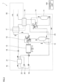
- FIG. 1 is a refrigerant circuit diagram illustrating an example configuration of a refrigeration cycle system according to an exemplary embodiment.
- the refrigeration cycle system 1 includes a refrigerant circuit 10 and a cold/hot water circuit 50.
- the refrigerant circuit 10 is filled with a natural refrigerant such as carbon dioxide or propane.
- the cold/hot water circuit 50 is filled with water, for example.
- the refrigeration cycle system 1 includes, for example, a control unit 100 as a means to control switching between a plurality of defrosting operation modes.
- the refrigerant circuit 10 includes a first compressor 11, a second compressor 12, an air heat exchanger 13, a switching valve 14, a four-way valve 15, a first water heat exchanger 16, a second water heat exchanger 17, a first expansion valve 18, a second expansion valve 19, a third expansion valve 20, an intermediate heat exchanger 21, and a bypass circuit 22.
- the refrigerant circuit 10 also includes a first flow path 25 connecting the suction side of the first compressor 11 and the suction side of the second compressor 12.
- the refrigerant circuit 10 also includes a second flow path 24 (see FIG. 6 ) connecting a point between the second water heat exchanger 17 and the second expansion valve 19 and a point between the first water heat exchanger 16 and the second compressor 12.
- the first and second compressors 11, 12 suck in refrigerant from their suction side and discharge the compressed refrigerant from their discharge side.
- the first and second compressors 11, 12 may include, at their suction side, an accumulator to separate the refrigerant into gas and liquid.
- the first compressor 11 has its discharge side connected to a third port (P3) of the switching valve 14 and has its suction side connected to a third port (P7) of the four-way valve 15.
- the second compressor 12 has its discharge side connected to a first port (P5) of the four-way valve 15 and has its suction side connected to the first water heat exchanger 16 and the bypass circuit 22.
- the flow of refrigerant is switched by switching between operation modes as described below.
- the air heat exchanger 13 exchanges heat between the refrigerant and the outdoor air.
- the air heat exchanger 13 functions as an evaporator during heating operation and as a condenser during cooling operation.
- the air heat exchanger 13 may be configured with an outdoor fan.
- the switching valve 14 switches connection/disconnection of a flow path between the first compressor 11 and the first water heat exchanger 16 and the first flow path 25.
- the switching valve 14 is a four-way valve and includes a first port (P1), a second port (P2), a third port (P3), and a fourth port (P4).
- the switching valve 14 can switch between a state where the first port (P1) and the second port (P2) are in communication with each other and the third port (P3) and the fourth port (P4) are in communication with each other, and a state where the first port (P1) and the fourth port (P4) are in communication with each other and the second port (P2) and the third port (P3) are in communication with each other.
- the four-way valve 15 includes a first port (P5), a second port (P6), a third port (P7), and a fourth port (P8).
- the four-way valve 15 can switch between a state where the first port (P5) and the second port (P6) are in communication with each other and the third port (P7) and the fourth port (P8) are in communication with each other, and a state where the first port (P5) and the fourth port (P8) are in communication with each other and the second port (P6) and the third port (P7) are in communication with each other.
- the first and second water heat exchangers 16, 17 each exchange heat between the refrigerant circuit 10 and the cold/hot water circuit 50.
- the first and second water heat exchangers 16, 17 function as condensers in the refrigerant circuit 10.
- the water flowing through the piping in the cold/hot water circuit 50 is heated by taking heat from the refrigerant circuit 10, thereby performing the heating function.
- the first, second, and third expansion valves 18, 19, 20 have a variable opening and have the function of lowering the pressure of refrigerant circulating in the refrigerant circuit 10 to expand the refrigerant.
- the intermediate heat exchanger 21 exchanges heat between the refrigerant flowing through the piping between the first and second expansion valves 18, 19 and the refrigerant decompressed by the third expansion valve 20 in the bypass circuit 22 that branches off at a branch point between the first expansion valve 18 and the intermediate heat exchanger 21.
- the refrigerant flowing in the bypass circuit 22 is regulated by the third expansion valve 20 as regards its amount passing therethrough and is thus decompressed to a lowered refrigerant temperature.
- the refrigerant with the lowered temperature passes through the intermediate heat exchanger 21 while exchanging heat with the refrigerant flowing through the piping between the first and second expansion valves 18, 19. After passing through the intermediate heat exchanger 21, the refrigerant joins the refrigerant flowing from the first water heat exchanger 16 into the second compressor 12, just before the second compressor 12.
- the configuration of the refrigerant circuit 10 is not limited to that described above.
- the refrigerant circuit 10 may be configured without the bypass circuit 22 including the third expansion valve 20 and the intermediate heat exchanger 21.
- the refrigerant circuit 10 may also be configured without the second expansion valve 19.
- the refrigerant circuit 10 may further be configured with a filter, heat sink, oil separator, and the like.
- the refrigerant circuit 10 may further be configured with a high-pressure switchgear as a protective detector.
- the switching valve 14 enables communication between the first port (P1) and the fourth port (P4) and communication between the second port (P2) and the third port (P3).
- the four-way valve 15 enables communication between the first port (P5) and the second port (P6) and communication between the third port (P7) and the fourth port (P8).
- the refrigerant circulates along the arrows shown in FIG. 1 . More specifically, the refrigerant is first compressed by the first compressor 11. The compressed refrigerant passes through the switching valve 14 and enters the first water heat exchanger 16. The refrigerant leaving the first water heat exchanger 16 is compressed by the second compressor 12 and then passes through the four-way valve 15 and enters the second water heat exchanger 17. The refrigerant leaving the second water heat exchanger 17 is decompressed by the first expansion valve 18 and enters the intermediate heat exchanger 21. The refrigerant entering the bypass circuit 22, which branches off at the branch point between the first expansion valve 18 and the intermediate heat exchanger 21, leaves the bypass circuit 22 and joins the refrigerant flowing from the first water heat exchanger 16 into the second compressor 12, just before the second compressor 12.
- the refrigerant entering the intermediate heat exchanger 21 is decompressed by the second expansion valve 19 and enters the air heat exchanger 13.
- the refrigerant leaving the air heat exchanger 13 passes through the four-way valve 15 and enters the first compressor 11.
- the first and second water heat exchangers 16, 17 function as condensers.
- the water flowing through the piping of the cold/hot water circuit 50 is heated by taking heat from the refrigerant flowing through the piping of the refrigerant circuit 10 and sent to the utilization side, thus performing the heating function.
- the cold/hot water circuit 50 exchanges heat with the refrigerant circuit 10 via the first and second water heat exchangers 16, 17 to provide heat exchange-based functions.
- the refrigerant circuit 10 and the cold/hot water circuit 50 function as a heating and hot water supply system, for example.
- a heating and hot water supply system consists of, for example, an outdoor unit and a tank unit.
- the outdoor unit includes the refrigerant circuit 10 and the tank unit includes the cold/hot water circuit 50.
- the connection between the outdoor unit and the tank unit may be made by connecting the piping of the refrigerant circuit 10 to the tank unit or by connecting the piping of the cold/hot water circuit 50 to the outdoor unit.
- FIG. 2 is a refrigerant circuit diagram illustrating an example configuration of the cold/hot water circuit 50 when the refrigeration cycle system 1 according to the present embodiment is used as a heating and hot water supply system.
- the cold/hot water circuit 50 When the cold/hot water circuit 50 is used as a heating and hot water supply system, the cold/hot water circuit 50 includes, for example, a three-way cock 51, a tank 52, a heat exchanger 53, a pump 54, and water piping 55 to 59, in addition to the first and second water heat exchangers 16, 17.
- the water flowing in the water piping 55 of the cold/hot water circuit 50 is driven by the pump 54 and circulates in the piping.
- the water flowing in the water piping passes through the first and second water heat exchangers 16, 17, during which the water is heated through a heat exchange with the refrigerant flowing in the refrigerant circuit 10.
- the hot water leaving the second water heat exchanger 17 is sent by the three-way cock 51 to the tank 52 or the water piping 56, depending on its use.
- the three-way cock 51 sends the hot water to the water piping 56.
- the water piping 56 leads to each room which uses heating, thus performing heating function in each room.
- the water that has been used for heating and is now thus cooled returns from the water piping 59.
- the water returned from the water piping 59 enters the first and second water heat exchangers 16, 17, where it is heated by heat exchange before being sent to each room again.
- the three-way cock 51 sends the hot water to the tank 52.
- the tank 52 stores hot water, and the heat exchanger 53 exchanges heat between the water flowing in the water piping 55 and the hot water stored in tank 52.
- the hot water stored in the tank 52 is heated by the heat exchanger 53 and sent to the water piping 57 for use as showering or other hot water supply.
- the water flowing in the water piping 55 is cooled by the heat exchanger 53 and enters the first and second water heat exchangers 16, 17, in which it is heated through a heat exchange before being sent to the tank 52 again.
- the tank 52 is replenished with city water or the like from the water piping 58.
- the refrigeration cycle system 1 can switch between a plurality of defrosting operation modes according to at least one of the water temperature and the amount of frosting.
- the amount of frosting is estimated by the outdoor air temperature and a temperature sensor (not shown) installed in the air heat exchanger 13.
- switching between the defrosting operation modes is performed by the control unit 100.
- the control unit 100 switches the defrosting operation modes in response to conditions for switching to another defrosting operation mode (described below) being met while one defrosting operation mode is in use.
- the plurality of defrosting operation modes includes a mode in which both the first and second compressors 11, 12 are used and a mode in which either the first compressor 11 or the second compressor 12 is used.
- the plurality of defrosting operation modes also includes a mode in which the first water heat exchanger 16 is used and a mode in which the first water heat exchanger 16 is not used.
- the manner of switching between the defrosting operation modes is not limited to that described above.
- the defrosting operation modes may be switched by user's selection.
- the defrosting operation modes that can be switched as well as their switching conditions are described below.
- the first defrosting operation mode is used.
- the normal defrosting operation refers to operation during which, for example, conditions for switching to any of other defrosting operation modes described below are not met.
- the first defrosting operation mode is basically used.
- the first defrosting operation mode is described with reference to FIG. 3.
- FIG. 3 is a refrigerant circuit diagram illustrating refrigerant flow during the first defrosting operation mode.
- the switching valve 14 enables communication between the first port (P1) and the second port (P2) and communication between the third port (P3) and the fourth port (P4). Also, the four-way valve 15 enables communication between the first port (P5) and the fourth port (P8) and communication between and the second port (P6) and the third port (P7).
- the refrigerant circulates along the arrows shown in FIG. 3 . More specifically, the refrigerant is first compressed by the first compressor 11. The compressed refrigerant enters the first flow path 25 through the switching valve 14 and then enters the second compressor 12. The refrigerant compressed by the second compressor 12 passes through the four-way valve 15 and enters the air heat exchanger 13. The air heat exchanger 13 functions as a condenser and radiates heat to perform the defrosting function. The refrigerant leaving the air heat exchanger 13 passes through the second expansion valve 19, the intermediate heat exchanger 21, and the first expansion valve 18 and enters the second water heat exchanger 17.
- the third expansion valve 20 is closed and no refrigerant flows in the bypass circuit 22, so that no heat exchange takes place in the intermediate heat exchanger 21.
- the refrigerant leaving the air heat exchanger 13 is decompressed by the second expansion valve 19 and then by the first expansion valve 18 and takes heat from the cold/hot water circuit 50 in the second water heat exchanger 17.
- the refrigerant leaving the second water heat exchanger 17 passes through the four-way valve 15 and again enters the first compressor 11. The refrigerant circulates in this manner during the first defrosting operation mode.
- both the first and second compressors 11, 12 are in operation.
- the second water heat exchanger 17 is used as an evaporator, and cold water is produced in the second water heat exchanger 17 as the refrigerant circuit 10 takes heat from the cold/hot water circuit 50.
- the first water heat exchanger 16 is not used during the first defrosting operation mode.
- the volume of the refrigeration cycle system 1 is reduced by not using the first water heat exchanger 16, which can increase the pressure of the refrigerant entering the air heat exchanger 13. This in turn enables efficient defrosting compared to when the refrigerant passes through the first water heat exchanger 16 between the first compressor 11 and the second compressor 12.
- the second defrosting operation mode is used to prevent freezing in the first and second water heat exchangers 16, 17.
- the low water temperature conditions refer to, for example, when the outlet water temperature of the cold/hot water circuit 50 is 15°C or lower.
- the second water heat exchanger 17 is used as an evaporator, and the refrigerant circuit 10 takes heat from the cold/hot water circuit 50, reducing the water temperature in the cold/hot water circuit 50.
- the first defrosting operation mode is switched to the second defrosting operation mode.
- the criterion for the low water temperature conditions is not limited to that described above and may be alterable.
- FIG. 4 is a refrigerant circuit diagram illustrating refrigerant flow during the second defrosting operation mode.
- the switching valve 14 enables communication between the first port (P1) and the fourth port (P4) and communication between the second port (P2) and the third port (P3).
- the four-way valve 15 enables communication between the first port (P5) and the fourth port (P8) and communication between the second port (P6) and the third port (P7).
- the refrigerant circulates along the arrows shown in FIG. 4 . More specifically, the refrigerant is first compressed by the first compressor 11. The compressed refrigerant passes through the switching valve 14 and enters the first water heat exchanger 16, which functions as a condenser. The refrigerant leaving the first water heat exchanger 16 enters the second compressor 12. The refrigerant compressed by the second compressor 12 passes through the four-way valve 15 and enters the air heat exchanger 13. The air heat exchanger 13 functions as a condenser and radiates heat to perform the defrosting function.
- the refrigerant leaving the air heat exchanger 13 passes through the second expansion valve 19, the intermediate heat exchanger 21, and the first expansion valve 18 and enters the second water heat exchanger 17.
- the third expansion valve 20 is closed and no refrigerant flows in the bypass circuit 22, so that no heat exchange takes place in the intermediate heat exchanger 21.
- the refrigerant leaving the air heat exchanger 13 is decompressed by the second expansion valve 19 and then by the first expansion valve 18 and takes heat from the cold/hot water circuit 50 in the second water heat exchanger 17.
- the refrigerant leaving the second water heat exchanger 17 passes through the four-way valve 15 and again enters the first compressor 11. The refrigerant circulates in this manner during the second defrosting operation mode.
- both the first and second compressors 11, 12 are in operation.
- the second water heat exchanger 17 is used as an evaporator, and cold water is produced in the second water heat exchanger 17 as the refrigerant circuit 10 takes heat from the cold/hot water circuit 50.
- the first water heat exchanger 16 is used as a condenser, and hot water is produced in the first water heat exchanger 16 as the cold/hot water circuit 50 takes heat from the refrigerant circuit 10.
- the first water heat exchanger 16 is used as a condenser to produce hot water, which prevents the temperature in the first and second water heat exchangers 16, 17 from falling below the freezing point. This configuration prevents freezing in the first and second water heat exchangers 16, 17.
- the third defrosting operation mode with reduced instantaneous power consumption is used.
- the condition of "when the amount of frosting is small” refers to, for example, when the outdoor air temperature is at or above 0°C and the temperature sensor installed in the air heat exchanger 13 reads -3°C or more.
- the criterion for determining the amount of frosting is not limited to that described above and may be settable.
- the condition of "when the duration of the defrosting operation does not need to be short” refers to, for example, when there is no need to perform defrosting in a hurry, such as when the defrosting operation is performed in preparation for the next operation after the heating operation was stopped.
- FIG. 5 is a refrigerant circuit diagram illustrating refrigerant flow during the third defrosting operation mode.
- the switching valve 14 enables communication between the first port (P1) and the fourth port (P4) and communication between the second port (P2) and the third port (P3).
- the four-way valve 15 enables communication between the first port (P5) and the fourth port (P8) and communication between the second port (P6) and the third port (P7).
- the refrigerant circulates along the arrows shown in FIG. 5 . More specifically, the refrigerant is first compressed by the second compressor 12. The compressed refrigerant passes through the four-way valve 15 and enters the air heat exchanger 13. The air heat exchanger 13 functions as a condenser and radiates heat to perform the defrosting function.
- the refrigerant leaving the air heat exchanger 13 passes through the second expansion valve 19, the intermediate heat exchanger 21, and the first expansion valve 18 and enters the second water heat exchanger 17.
- the third expansion valve 20 is closed and no refrigerant flows in the bypass circuit 22, so that no heat exchange takes place in the intermediate heat exchanger 21.
- the refrigerant leaving the air heat exchanger 13 is decompressed by the second expansion valve 19 and then by the first expansion valve 18 and takes heat from the cold/hot water circuit 50 in the second water heat exchanger 17.
- the refrigerant leaving the second water heat exchanger 17 passes through the four-way valve 15 and the switching valve 14 and again enters the second compressor 12. The refrigerant circulates in this manner during the third defrosting operation mode.
- the second compressor 12 is in operation, but the first compressor 11 is stopped.
- the second water heat exchanger 17 is used as an evaporator, and cold water is produced in the second water heat exchanger 17 as the refrigerant circuit 10 takes heat from the cold/hot water circuit 50.
- the first water heat exchanger 16 is not used.
- the first compressor 11 is stopped under conditions that do not require a high defrosting capacity, such as when the amount of frosting is small, thus enabling the defrosting operation to be performed with reduced instantaneous power consumption.
- the fourth defrosting operation mode is used, in which the first and second water heat exchangers 16, 17 are used as evaporators.
- the condition of "when the amount of frosting is large” refers to, for example, when the outdoor air temperature is at or below 5°C and the difference between the outdoor air temperature and the reading of the temperature sensor of the air heat exchanger is 10°C or more.
- the criterion for determining the amount of frosting is not limited to that described above and may be settable.
- FIG. 6 is a refrigerant circuit diagram illustrating refrigerant flow during the fourth defrosting operation mode.
- the fourth defrosting operation mode utilizes the second flow path 24 with a fourth expansion valve 23, through which the refrigerant is bypassed from a point between the second water heat exchanger 17 and the air heat exchanger 13 to a point between the first water heat exchanger 16 and the second compressor 12.
- a fourth expansion valve 23 through which the refrigerant is bypassed from a point between the second water heat exchanger 17 and the air heat exchanger 13 to a point between the first water heat exchanger 16 and the second compressor 12.
- FIGS. 1 and 3 through 5 the illustration of the second flow path 24 is omitted.
- the switching valve 14 enables communication between the first port (P1) and the second port (P2) and communication between the third port (P3) and the fourth port (P4).
- the four-way valve 15 enables communication between the first port (P5) and the fourth port (P8) and communication between the second port (P6) and the third port (P7).
- the refrigerant circulates along the arrows shown in FIG. 6 . More specifically, the refrigerant is first compressed by the first compressor 11. The compressed refrigerant enters the first flow path 25 through the switching valve 14 and then enters the second compressor 12. The refrigerant compressed by the second compressor 12 passes through the four-way valve 15 and enters the air heat exchanger 13. The air heat exchanger 13 functions as a condenser and radiates heat to perform the defrosting function.
- the refrigerant leaving the air heat exchanger 13 passes through the second expansion valve 19 and the intermediate heat exchanger 21 and is decompressed by the second expansion valve 19.
- the third expansion valve 20 is closed and no refrigerant flows in the bypass circuit 22, so that no heat exchange takes place in the intermediate heat exchanger 21.
- the refrigerant leaving the intermediate heat exchanger 21 splits into two paths, one leading to the second water heat exchanger 17 through the first expansion valve 18 and the other passing through the second flow path 24.
- the refrigerant entering the second water heat exchanger 17 takes heat from the cold/hot water circuit 50 and then passes through the four-way valve 15 and enters the first compressor 11.
- the refrigerant entering the second flow path 24 is decompressed by the fourth expansion valve 23 and enters the first water heat exchanger 16.
- the refrigerant entering the first water heat exchanger 16 takes heat from the cold/hot water circuit 50.
- the refrigerant then passes through the switching valve 14 and merges into the branched-off circuit just before the first compressor 11, finally entering the first compressor 11.
- the refrigerant circulates in this manner during the fourth defrosting operation mode.
- both the first and second compressors 11, 12 are in operation. Also, during the fourth defrosting operation mode, both the first and second water heat exchangers 16, 17 are used as evaporators by utilizing the second flow path 24. By nature of the evaporator function, the refrigerant circuit 10 takes heat from the cold/hot water circuit 50, thus producing cold water in both the first and second water heat exchangers 16, 17.
- both the first and second water heat exchangers 16, 17 are used as evaporators, and the refrigerant compressed by the first and second compressors 11, 12 is sent to the air heat exchanger 13. This enables a high-capacity defrosting operation.
- the fourth defrosting operation mode is used, in which no refrigerant flows in the first and second water heat exchangers 16, 17.
- the condition of "when the water temperature is extremely low” refers to, for example, the outlet water temperature of the cold/hot water circuit 50 is at or below 5°C.
- the condition of "when the water temperature drop is to be inhibited” refers to, for example, when the difference between the temperature of water supplied to the room and the hot water outlet temperature set by a user is 5°C or more or when the room temperature has dropped by 3°C or more. Note that the reference values are not limited to these, and the values based on which the operation modes are switched may be alterable.
- FIG. 7 is a refrigerant circuit diagram illustrating refrigerant flow during the fifth defrosting operation mode.
- the fifth defrosting operation mode utilizes the second flow path 24 with the fourth expansion valve 23, through which the refrigerant is bypassed from a point between the second water heat exchanger 17 and the air heat exchanger 13 to a point between the first water heat exchanger 16 and the second compressor 12.
- the first expansion valve 18 is closed, and no refrigerant flows in the second water heat exchanger 17.
- the four-way valve 15 enables communication between the first port (P5) and the fourth port (P8) and communication between the second port (P6) and the third port (P7).
- the refrigerant circulates along the arrows shown in FIG. 7 . More specifically, the refrigerant is first compressed by the second compressor 12. The compressed refrigerant passes through the four-way valve 15 and enters the air heat exchanger 13. The air heat exchanger 13 functions as a condenser and radiates heat to perform the defrosting function.
- the refrigerant leaving the air heat exchanger 13 passes through the second expansion valve 19 and the intermediate heat exchanger 21 and is decompressed by the second expansion valve 19.
- the third expansion valve 20 is closed and no refrigerant flows in the bypass circuit 22, so that no heat exchange takes place in the intermediate heat exchanger 21.
- the refrigerant leaving the intermediate heat exchanger 21 enters the second flow path 24 and is decompressed by the fourth expansion valve 23.
- the decompressed refrigerant enters the second compressor 12 again.
- the refrigerant circulates in this manner during the fifth defrosting operation mode.
- the second compressor 12 is in operation, but the first compressor 11 is stopped. Also, during the fourth defrosting operation mode, the second flow path 24 is utilized, so that neither the first water heat exchanger 16 nor the second water heat exchanger 17 is used.
- neither the first water heat exchanger 16 nor the second water heat exchanger 17 is used. Since no heat exchange takes place in the first and second water heat exchangers 16, 17, water temperature drop can be prevented.
- FIG. 8 is a flowchart illustrating an example process performed for switching the defrosting operation modes according to the present embodiment.
- the process of switching the defrosting operation modes is performed by the control unit 100.
- the control unit 100 first determines whether the water temperature is at or below a first threshold (step S101). If the water temperature is at or below the first threshold (YES in step S101), the control unit 100 determines whether the water temperature is at or below a second threshold, which is lower than the first threshold (step S102). If the water temperature is at or below the second threshold (YES in step S102), the fifth defrosting operation mode is used for defrosting operation (step S103). On the other hand, if the water temperature is at or above the second threshold (NO in step S102), the second defrosting operation mode is used for defrosting operation (step S104).
- the first threshold is a threshold for using the second defrosting operation mode
- the second threshold is a threshold for using the fifth defrosting operation mode.
- the first threshold is set higher than the second threshold. If the water temperature is between the first threshold and the second threshold, the second defrosting operation mode is used.
- step S105 determines whether it is necessary to inhibit the water temperature drop. If it is necessary to inhibit the water temperature drop (YES in step S105), the fifth defrosting operation mode is used for defrosting operation (step S103). On the other hand, if it is not necessary to inhibit the water temperature drop (NO in step S 105), the control unit 100 determines whether the duration of the defrosting operation needs to be short (step S 106).
- the condition of when the duration of the defrosting operation does not need to be short refers to, for example, when there is no need to perform defrosting in a hurry, such as when the defrosting operation is performed in preparation for the next operation after the heating operation was stopped.
- step S 106 the control unit 100 accepts a user's selection as to whether the duration of the defrosting operation needs to be short.
- the control unit 100 may be configured to determine that the duration of the defrosting operation does not need to be short depending on, for example, the time when the heating operation ended. For example, if the heating operation ended after 12:00 pm, the control unit 100 may determine that the duration of the defrosting operation does not need to be short because there will be time until the next heating operation is started.
- step S108 If the duration of the defrosting operation does not need to be short (NO in step S 106), the third defrosting operation mode is used for defrosting operation (step S108).
- step S 106 determines whether the amount of frosting is greater than a first threshold (step S 107). If the amount of frosting is less than the first threshold (NO in step S 107), the third defrosting operation mode is used for defrosting operation (step S 108).
- step S109 a determination is made as to whether the defrosting operation needs to be finished in a shorter duration than the defrosting duration determined in step S106.
- condition of "if the defrosting operation needs to be finished quickly” refers to, for example, when defrosting needs to be done in a hurry, such as when the defrosting operation is performed before starting the heating operation.
- step S109 If the defrosting operation needs to be finished quickly (YES in step S109), the fourth defrosting operation mode is used for defrosting operation (step S111). On the other hand, if the defrosting operation does not need to be finished quickly (NO in step S109), the control unit 100 determines whether the amount of frosting is greater than a second threshold (step S110).
- the second threshold for the amount of frosting used in step S110 is set higher than the first threshold for the amount of frosting used in step S107. In step S110, it is determined whether a strong defrosting operation is required.
- step S110 If the amount of frosting is greater than the second threshold in step S110 (YES in step S110), the fourth defrosting operation mode is used for defrosting operation (step S111).
- the first defrosting operation mode is used for defrosting operation (step S112).
- the process shown in FIG. 8 is performed for switching from one defrosting operation mode in use to another defrosting operation mode.
- the process shown in FIG. 8 is also performed at the start of defrosting operation, whereby one of the defrosting operation modes is selected.
- one predetermined defrosting operation mode may always be used at the start of defrosting operation and then may be switched to another defrosting operation mode through the process shown in FIG. 8 .
- control unit 100 may be configured to perform another step prior to step S101 in FIG. 8 .
- control unit 100 may be configured to first perform step 110 in FIG. 8 , i.e., determine whether the amount of frosting is greater than the threshold and, if the amount of frosting is greater than the threshold, use the fourth defrosting operation mode.
- control unit 100 may be configured to perform only one of steps S106 and S107 to determine whether the third defrosting operation mode is to be used.
- control unit 100 may also be configured to perform only one of steps S109 and S110 to determine whether the third defrosting operation mode is to be used.
- control unit 100 may be configured to, if the water temperature is determined to be at or above the first threshold in step S101 in FIG. 8 (NO in step S101), perform steps S109 and S110 prior to steps S106 and S107. In this case, the determination of whether to use the fourth defrosting operation mode is made prior to the determination of whether to use the third defrosting operation mode.
- the control unit 100 may also be configured to, even if, for example, the water temperature is determined to be at or above the second threshold in step S102 of FIG. 8 (NO in step S102), perform step 105 and subsequent steps to enable switching to another defrosting operation mode.
- the control unit 100 may be configured to switch to the fifth defrosting operation mode in response to the water temperature falling to or below the second threshold.
- the refrigeration cycle system 1 includes at least two compressors, four-way valves, water heat exchangers, at least one air heat exchanger, and a plurality of expansion valves, and configured to switch between a plurality of defrosting operation modes during defrosting operation by switching the four-way valves according to at least one of the water temperature and the amount of frosting.
- the refrigeration cycle system 1 includes: the first compressor 11; the first water heat exchanger 16; the second compressor 12; the four-way valve 15; the second water heat exchanger 17; the second expansion valve 19; the air heat exchanger 13; the main flow path along which refrigerant flows through the first compressor 11, the first water heat exchanger 16, the second compressor 12, the four-way valve 15, the second water heat exchanger 17, the second expansion valve 19, and the air heat exchanger 13 in this order during heating operation; the first flow path 25 connecting the suction side of the first compressor 11 in the main flow path and the suction side of the second compressor 12 in the main flow path; and the second flow path 24 connecting a point between the second water heat exchanger 17 and the second expansion valve 19 in the main flow path and a point between the first water heat exchanger 16 and the second compressor 12 in the main flow path.
- the four-way valve 15 is switchable between connecting the second compressor 12 and the second water heat exchanger 17 and connecting the second compressor 12 and the air heat exchanger 13, and the refrigeration cycle system 1 is configured to perform defrosting operation while switching between a plurality of defrosting operation modes. This configuration enables switching between a plurality of defrosting operation modes at reduced costs.
- the plurality of defrosting operation modes includes a mode in which both the first compressor 11 and the second compressor 12 are used and a mode in which either the first compressor 11 or the second compressor 12 is used.
- the refrigeration cycle system of the present disclosure further includes the switching valve 14 configured to switch connection/disconnection of the flow path between the first compressor 11 and the first water heat exchanger 16 in the main flow path to/from the first flow path 25.
- the plurality of defrosting operation modes includes the first defrosting operation mode in which the refrigerant flows through the first compressor 11, the first flow path 25, the second compressor 12, the air heat exchanger 13, and the second water heat exchanger 17 in this order and then returns to the first compressor 11.
- This mode enables a defrosting operation with a reduced volume of the refrigeration cycle system 1.
- the plurality of defrosting operation modes includes the second defrosting operation mode in which the refrigerant flows through the first compressor 11, the first water heat exchanger 16, the second compressor 12, the air heat exchanger 13, and the second water heat exchanger 17 in this order and then returns to the first compressor 11. This mode can prevent freezing in the first and second water heat exchangers.
- the plurality of defrosting operation modes includes the third defrosting operation mode in which the refrigerant flows through the second compressor 12, the air heat exchanger 13, the second water heat exchanger 17, and the first flow path 25 in this order and then returns to the second compressor 12. This mode enables a defrosting operation with reduced instantaneous power consumption.
- the plurality of defrosting operation modes includes the fourth defrosting operation mode in which the refrigerant flows through the first compressor 11, the first flow path 25, the second compressor 12, and the air heat exchanger 13 in this order and then splits into one flow path and another flow path through each of which the refrigerant returns to the first compressor 11, the one flow path leading to the suction side of the first compressor 11 through the second water heat exchanger 17, the another flow path leading to the suction side of the first compressor 11 through the second flow path 24 and the first water heat exchanger 16.
- This mode enables a high-capacity defrosting operation.
- the plurality of defrosting operation modes includes the fifth defrosting operation mode in which the refrigerant flows through the second compressor 12, the air heat exchanger 13, and the second flow path 24 in this order and then returns to the second compressor 12. This mode can prevent water temperature drop in the first and second water heat exchangers.
- the defrosting operation modes are switched according to the amount of frosting. This allows for controlling switching between the plurality of defrosting operation modes according to predetermined conditions.
- the amount of frosting is estimated by outdoor air temperature and the temperature sensor attached to the air heat exchanger 13.
- the defrosting operation modes are switched according to water temperature. This allows for controlling switching between the plurality of defrosting operation modes according to predetermined conditions.
- the refrigerant is carbon dioxide.
Landscapes
- Engineering & Computer Science (AREA)
- Physics & Mathematics (AREA)
- Mechanical Engineering (AREA)
- Thermal Sciences (AREA)
- General Engineering & Computer Science (AREA)
- Heat-Pump Type And Storage Water Heaters (AREA)
Abstract
Description
- The present disclosure relates to a refrigeration cycle system.
-
Patent Literature 1 discloses a hot water heater that uses a bypass circuit and an auxiliary heater to prevent freezing of a water heat exchanger disposed in the hot water heater during defrosting operation of a heat-pump hot-water supply outdoor unit connected to the hot water heater. - Patent Literature 1:
Japanese Patent No. 5573757 - In a refrigeration cycle system such as a heating and hot water supply system, for example, performing heating operation under low-temperature outdoor air conditions leads to gradual frost formation in the outdoor heat exchanger, reducing heating capacity over time. To prevent such decrease in heating capacity, defrosting operation is performed. However, during defrosting operation, the refrigeration cycle system is in a cooling cycle and the water heat exchanger serves as an evaporator, so that the water temperature drops and the water in the water heat exchanger may freeze. For example, an auxiliary heater may be provided upstream of the water heat exchanger to prevent such freezing, but this requires additional costs.
- An object of the present disclosure is to switch between a plurality of defrosting operation modes at reduced costs.
- A refrigeration cycle system according to the present disclosure includes: a first compressor (11); a first water heat exchanger (16); a second compressor (12); a four-way valve (15); a second water heat exchanger (17); an expansion valve (19); an air heat exchanger (13); a main flow path along which refrigerant flows through the first compressor (11), the first water heat exchanger (16), the second compressor (12), the four-way valve (15), the second water heat exchanger (17), the expansion valve (19), and the air heat exchanger (13) in this order during heating operation; a first flow path (25) connecting a suction side of the first compressor (11) in the main flow path and a suction side of the second compressor (12) in the main flow path; and a second flow path (24) connecting a point between the second water heat exchanger (17) and the expansion valve (19) in the main flow path and a point between the first water heat exchanger (16) and the second compressor (12) in the main flow path. The four-way valve (15) is switchable between connecting the second compressor (12) and the second water heat exchanger (17) and connecting the second compressor (12) and the air heat exchanger (13), and the refrigeration cycle system is configured to perform defrosting operation while switching between a plurality of defrosting operation modes. This configuration enables switching between the plurality of defrosting operation modes at reduced costs.
- The plurality of defrosting operation modes includes a mode in which both the first compressor (11) and the second compressor (12) are used and a mode in which either the first compressor (11) or the second compressor (12) is used.
- The refrigeration cycle system according to the present disclosure further includes a switching valve (14) configured to switch connection/disconnection of a flow path between the first compressor (11) and the first water heat exchanger (16) in the main flow path to/from the first flow path (25).
- The plurality of defrosting operation modes includes a first defrosting operation mode in which the refrigerant flows through the first compressor (11), the first flow path (25), the second compressor (12), the air heat exchanger (13), and the second water heat exchanger (17) in this order and then returns to the first compressor (11). This mode enables a defrosting operation with a reduced volume of the
refrigeration cycle system 1. - The plurality of defrosting operation modes includes a second defrosting operation mode in which the refrigerant flows through the first compressor (11), the first water heat exchanger (16), the second compressor (12), the air heat exchanger (13), and the second water heat exchanger (17) in this order and then returns to the first compressor (11). This mode can prevent freezing in the first and second water heat exchangers.
- The plurality of defrosting operation modes includes a third defrosting operation mode in which the refrigerant flows through the second compressor (12), the air heat exchanger (13), the second water heat exchanger (17), and the first flow path (25) in this order and then returns to the second compressor (12). This mode enables a defrosting operation with reduced instantaneous power consumption.
- The plurality of defrosting operation modes includes a fourth defrosting operation mode in which the refrigerant flows through the first compressor (11), the first flow path (25), the second compressor (12), and the air heat exchanger (13) in this order and then splits into one flow path and another flow path through each of which the refrigerant returns to the first compressor (11), the one flow path leading to the suction side of the first compressor (11) through the second water heat exchanger (17), the another flow path leading to the suction side of the first compressor (11) through the second flow path and the first water heat exchanger (16). This mode enables a high-capacity defrosting operation.
- The plurality of defrosting operation modes includes a fifth defrosting operation mode in which the refrigerant flows through the second compressor (12), the air heat exchanger (13), and the second flow path (24) in this order and then returns to the second compressor (12). This mode can prevent water temperature drop in the first and second water heat exchangers.
- The defrosting operation modes are switched according to an amount of frosting. This allows for controlling switching between the plurality of defrosting operation modes according to predetermined conditions.
- The amount of frosting is estimated by outdoor air temperature and a temperature sensor attached to the air heat exchanger (13).
- The defrosting operation modes are switched according to water temperature. This allows for controlling switching between the plurality of defrosting operation modes according to predetermined conditions.
- The refrigerant is carbon dioxide.
-
-
FIG. 1 is a refrigerant circuit diagram illustrating an example configuration of a refrigeration cycle system according to an exemplary embodiment. -
FIG. 2 is a refrigerant circuit diagram illustrating an example configuration of a cold/hot water circuit when the refrigeration cycle system according to the exemplary embodiment is used as a heating and hot water supply system. -
FIG. 3 is a refrigerant circuit diagram illustrating refrigerant flow during a first defrosting operation mode. -
FIG. 4 is a refrigerant circuit diagram illustrating refrigerant flow during a second defrosting operation mode. -
FIG. 5 is a refrigerant circuit diagram illustrating refrigerant flow during a third defrosting operation mode. -
FIG. 6 is a refrigerant circuit diagram illustrating refrigerant flow during a fourth defrosting operation mode. -
FIG. 7 is a refrigerant circuit diagram illustrating refrigerant flow during a fifth defrosting operation mode. -
FIG. 8 is a flowchart illustrating an example process performed for switching the defrosting operation modes according to the exemplary embodiment. - An exemplary embodiment is detailed below with reference to the appended drawings.
-
FIG. 1 is a refrigerant circuit diagram illustrating an example configuration of a refrigeration cycle system according to an exemplary embodiment. - The
refrigeration cycle system 1 according to the present embodiment includes arefrigerant circuit 10 and a cold/hot water circuit 50. For example, therefrigerant circuit 10 is filled with a natural refrigerant such as carbon dioxide or propane. The cold/hot water circuit 50 is filled with water, for example. - The
refrigeration cycle system 1 according to the present embodiment includes, for example, acontrol unit 100 as a means to control switching between a plurality of defrosting operation modes. - The
refrigerant circuit 10 includes afirst compressor 11, asecond compressor 12, anair heat exchanger 13, aswitching valve 14, a four-way valve 15, a firstwater heat exchanger 16, a secondwater heat exchanger 17, afirst expansion valve 18, asecond expansion valve 19, athird expansion valve 20, anintermediate heat exchanger 21, and abypass circuit 22. Therefrigerant circuit 10 also includes afirst flow path 25 connecting the suction side of thefirst compressor 11 and the suction side of thesecond compressor 12. Therefrigerant circuit 10 also includes a second flow path 24 (seeFIG. 6 ) connecting a point between the secondwater heat exchanger 17 and thesecond expansion valve 19 and a point between the firstwater heat exchanger 16 and thesecond compressor 12. - The first and
second compressors second compressors first compressor 11 has its discharge side connected to a third port (P3) of theswitching valve 14 and has its suction side connected to a third port (P7) of the four-way valve 15. Thesecond compressor 12 has its discharge side connected to a first port (P5) of the four-way valve 15 and has its suction side connected to the firstwater heat exchanger 16 and thebypass circuit 22. The flow of refrigerant is switched by switching between operation modes as described below. - The air heat exchanger 13 exchanges heat between the refrigerant and the outdoor air. The air heat exchanger 13 functions as an evaporator during heating operation and as a condenser during cooling operation. The
air heat exchanger 13 may be configured with an outdoor fan. - The
switching valve 14 switches connection/disconnection of a flow path between thefirst compressor 11 and the firstwater heat exchanger 16 and thefirst flow path 25. In the present embodiment, theswitching valve 14 is a four-way valve and includes a first port (P1), a second port (P2), a third port (P3), and a fourth port (P4). Theswitching valve 14 can switch between a state where the first port (P1) and the second port (P2) are in communication with each other and the third port (P3) and the fourth port (P4) are in communication with each other, and a state where the first port (P1) and the fourth port (P4) are in communication with each other and the second port (P2) and the third port (P3) are in communication with each other. - The four-
way valve 15 includes a first port (P5), a second port (P6), a third port (P7), and a fourth port (P8). The four-way valve 15 can switch between a state where the first port (P5) and the second port (P6) are in communication with each other and the third port (P7) and the fourth port (P8) are in communication with each other, and a state where the first port (P5) and the fourth port (P8) are in communication with each other and the second port (P6) and the third port (P7) are in communication with each other. - The first and second
water heat exchangers refrigerant circuit 10 and the cold/hot water circuit 50. For example, during heating operation, the first and secondwater heat exchangers refrigerant circuit 10. The water flowing through the piping in the cold/hot water circuit 50 is heated by taking heat from therefrigerant circuit 10, thereby performing the heating function. - The first, second, and
third expansion valves refrigerant circuit 10 to expand the refrigerant. - The
intermediate heat exchanger 21 exchanges heat between the refrigerant flowing through the piping between the first andsecond expansion valves third expansion valve 20 in thebypass circuit 22 that branches off at a branch point between thefirst expansion valve 18 and theintermediate heat exchanger 21. - The refrigerant flowing in the
bypass circuit 22 is regulated by thethird expansion valve 20 as regards its amount passing therethrough and is thus decompressed to a lowered refrigerant temperature. The refrigerant with the lowered temperature passes through theintermediate heat exchanger 21 while exchanging heat with the refrigerant flowing through the piping between the first andsecond expansion valves intermediate heat exchanger 21, the refrigerant joins the refrigerant flowing from the firstwater heat exchanger 16 into thesecond compressor 12, just before thesecond compressor 12. - The configuration of the
refrigerant circuit 10 is not limited to that described above. For example, therefrigerant circuit 10 may be configured without thebypass circuit 22 including thethird expansion valve 20 and theintermediate heat exchanger 21. Therefrigerant circuit 10 may also be configured without thesecond expansion valve 19. Therefrigerant circuit 10 may further be configured with a filter, heat sink, oil separator, and the like. Therefrigerant circuit 10 may further be configured with a high-pressure switchgear as a protective detector. - The flow of refrigerant in the
refrigerant circuit 10 during heating operation is now described with reference toFIG. 1 . During heating operation, the switchingvalve 14 enables communication between the first port (P1) and the fourth port (P4) and communication between the second port (P2) and the third port (P3). The four-way valve 15 enables communication between the first port (P5) and the second port (P6) and communication between the third port (P7) and the fourth port (P8). - During heating operation, the refrigerant circulates along the arrows shown in
FIG. 1 . More specifically, the refrigerant is first compressed by thefirst compressor 11. The compressed refrigerant passes through the switchingvalve 14 and enters the firstwater heat exchanger 16. The refrigerant leaving the firstwater heat exchanger 16 is compressed by thesecond compressor 12 and then passes through the four-way valve 15 and enters the secondwater heat exchanger 17. The refrigerant leaving the secondwater heat exchanger 17 is decompressed by thefirst expansion valve 18 and enters theintermediate heat exchanger 21. The refrigerant entering thebypass circuit 22, which branches off at the branch point between thefirst expansion valve 18 and theintermediate heat exchanger 21, leaves thebypass circuit 22 and joins the refrigerant flowing from the firstwater heat exchanger 16 into thesecond compressor 12, just before thesecond compressor 12. - Meanwhile, the refrigerant entering the
intermediate heat exchanger 21 is decompressed by thesecond expansion valve 19 and enters theair heat exchanger 13. The refrigerant leaving theair heat exchanger 13 passes through the four-way valve 15 and enters thefirst compressor 11. - During heating operation, the first and second
water heat exchangers hot water circuit 50 is heated by taking heat from the refrigerant flowing through the piping of therefrigerant circuit 10 and sent to the utilization side, thus performing the heating function. - The cold/
hot water circuit 50 exchanges heat with therefrigerant circuit 10 via the first and secondwater heat exchangers refrigerant circuit 10 and the cold/hot water circuit 50 function as a heating and hot water supply system, for example. - A heating and hot water supply system consists of, for example, an outdoor unit and a tank unit. When the
refrigeration cycle system 1 according to the present embodiment is used as a heating and hot water supply system, the outdoor unit includes therefrigerant circuit 10 and the tank unit includes the cold/hot water circuit 50. The connection between the outdoor unit and the tank unit may be made by connecting the piping of therefrigerant circuit 10 to the tank unit or by connecting the piping of the cold/hot water circuit 50 to the outdoor unit. - An example configuration for using the
refrigeration cycle system 1 according to the present embodiment as a heating and hot water supply system is described with reference toFIG. 2. FIG. 2 is a refrigerant circuit diagram illustrating an example configuration of the cold/hot water circuit 50 when therefrigeration cycle system 1 according to the present embodiment is used as a heating and hot water supply system. - When the cold/
hot water circuit 50 is used as a heating and hot water supply system, the cold/hot water circuit 50 includes, for example, a three-way cock 51, atank 52, aheat exchanger 53, apump 54, and water piping 55 to 59, in addition to the first and secondwater heat exchangers - The water flowing in the water piping 55 of the cold/
hot water circuit 50 is driven by thepump 54 and circulates in the piping. The water flowing in the water piping passes through the first and secondwater heat exchangers refrigerant circuit 10. The hot water leaving the secondwater heat exchanger 17 is sent by the three-way cock 51 to thetank 52 or thewater piping 56, depending on its use. - When heating is used, the three-
way cock 51 sends the hot water to thewater piping 56. Thewater piping 56 leads to each room which uses heating, thus performing heating function in each room. The water that has been used for heating and is now thus cooled returns from thewater piping 59. The water returned from thewater piping 59 enters the first and secondwater heat exchangers - When hot water is used, the three-
way cock 51 sends the hot water to thetank 52. Thetank 52 stores hot water, and theheat exchanger 53 exchanges heat between the water flowing in thewater piping 55 and the hot water stored intank 52. The hot water stored in thetank 52 is heated by theheat exchanger 53 and sent to thewater piping 57 for use as showering or other hot water supply. - Meanwhile, the water flowing in the
water piping 55 is cooled by theheat exchanger 53 and enters the first and secondwater heat exchangers tank 52 again. When the hot water stored in thetank 52 is used, thetank 52 is replenished with city water or the like from thewater piping 58. - During defrosting operation, the
refrigeration cycle system 1 according to the present embodiment can switch between a plurality of defrosting operation modes according to at least one of the water temperature and the amount of frosting. The amount of frosting is estimated by the outdoor air temperature and a temperature sensor (not shown) installed in theair heat exchanger 13. - For example, switching between the defrosting operation modes is performed by the
control unit 100. For example, in response to conditions for switching to another defrosting operation mode (described below) being met while one defrosting operation mode is in use, thecontrol unit 100 switches the defrosting operation modes. - The plurality of defrosting operation modes includes a mode in which both the first and
second compressors first compressor 11 or thesecond compressor 12 is used. The plurality of defrosting operation modes also includes a mode in which the firstwater heat exchanger 16 is used and a mode in which the firstwater heat exchanger 16 is not used. - The manner of switching between the defrosting operation modes is not limited to that described above. For example, the defrosting operation modes may be switched by user's selection. The defrosting operation modes that can be switched as well as their switching conditions are described below.
- During normal defrosting operation, the first defrosting operation mode is used. The normal defrosting operation refers to operation during which, for example, conditions for switching to any of other defrosting operation modes described below are not met. When defrosting operation is performed, the first defrosting operation mode is basically used. The first defrosting operation mode is described with reference to
FIG. 3. FIG. 3 is a refrigerant circuit diagram illustrating refrigerant flow during the first defrosting operation mode. - During the first defrosting operation mode, the switching
valve 14 enables communication between the first port (P1) and the second port (P2) and communication between the third port (P3) and the fourth port (P4). Also, the four-way valve 15 enables communication between the first port (P5) and the fourth port (P8) and communication between and the second port (P6) and the third port (P7). - During the first defrosting operation mode, the refrigerant circulates along the arrows shown in
FIG. 3 . More specifically, the refrigerant is first compressed by thefirst compressor 11. The compressed refrigerant enters thefirst flow path 25 through the switchingvalve 14 and then enters thesecond compressor 12. The refrigerant compressed by thesecond compressor 12 passes through the four-way valve 15 and enters theair heat exchanger 13. Theair heat exchanger 13 functions as a condenser and radiates heat to perform the defrosting function. The refrigerant leaving theair heat exchanger 13 passes through thesecond expansion valve 19, theintermediate heat exchanger 21, and thefirst expansion valve 18 and enters the secondwater heat exchanger 17. - During the first defrosting operation mode, the
third expansion valve 20 is closed and no refrigerant flows in thebypass circuit 22, so that no heat exchange takes place in theintermediate heat exchanger 21. The refrigerant leaving theair heat exchanger 13 is decompressed by thesecond expansion valve 19 and then by thefirst expansion valve 18 and takes heat from the cold/hot water circuit 50 in the secondwater heat exchanger 17. The refrigerant leaving the secondwater heat exchanger 17 passes through the four-way valve 15 and again enters thefirst compressor 11. The refrigerant circulates in this manner during the first defrosting operation mode. - During the first defrosting operation mode, both the first and
second compressors water heat exchanger 17 is used as an evaporator, and cold water is produced in the secondwater heat exchanger 17 as therefrigerant circuit 10 takes heat from the cold/hot water circuit 50. - On the other hand, the first
water heat exchanger 16 is not used during the first defrosting operation mode. During the first defrosting operation mode, the volume of therefrigeration cycle system 1 is reduced by not using the firstwater heat exchanger 16, which can increase the pressure of the refrigerant entering theair heat exchanger 13. This in turn enables efficient defrosting compared to when the refrigerant passes through the firstwater heat exchanger 16 between thefirst compressor 11 and thesecond compressor 12. - For defrosting operation under low water temperature conditions, the second defrosting operation mode is used to prevent freezing in the first and second
water heat exchangers hot water circuit 50 is 15°C or lower. - For example, during the first defrosting operation mode, the second
water heat exchanger 17 is used as an evaporator, and therefrigerant circuit 10 takes heat from the cold/hot water circuit 50, reducing the water temperature in the cold/hot water circuit 50. In response to the outlet water temperature of the cold/hot water circuit 50 falling to or below 15°C due to this temperature drop, the first defrosting operation mode is switched to the second defrosting operation mode. Note that the criterion for the low water temperature conditions is not limited to that described above and may be alterable. - The second defrosting operation mode is described with reference to
FIG. 4. FIG. 4 is a refrigerant circuit diagram illustrating refrigerant flow during the second defrosting operation mode. - During the second defrosting operation mode, the switching
valve 14 enables communication between the first port (P1) and the fourth port (P4) and communication between the second port (P2) and the third port (P3). The four-way valve 15 enables communication between the first port (P5) and the fourth port (P8) and communication between the second port (P6) and the third port (P7). - During the second defrosting operation mode, the refrigerant circulates along the arrows shown in
FIG. 4 . More specifically, the refrigerant is first compressed by thefirst compressor 11. The compressed refrigerant passes through the switchingvalve 14 and enters the firstwater heat exchanger 16, which functions as a condenser. The refrigerant leaving the firstwater heat exchanger 16 enters thesecond compressor 12. The refrigerant compressed by thesecond compressor 12 passes through the four-way valve 15 and enters theair heat exchanger 13. Theair heat exchanger 13 functions as a condenser and radiates heat to perform the defrosting function. - The refrigerant leaving the
air heat exchanger 13 passes through thesecond expansion valve 19, theintermediate heat exchanger 21, and thefirst expansion valve 18 and enters the secondwater heat exchanger 17. During the second defrosting operation mode, thethird expansion valve 20 is closed and no refrigerant flows in thebypass circuit 22, so that no heat exchange takes place in theintermediate heat exchanger 21. The refrigerant leaving theair heat exchanger 13 is decompressed by thesecond expansion valve 19 and then by thefirst expansion valve 18 and takes heat from the cold/hot water circuit 50 in the secondwater heat exchanger 17. The refrigerant leaving the secondwater heat exchanger 17 passes through the four-way valve 15 and again enters thefirst compressor 11. The refrigerant circulates in this manner during the second defrosting operation mode. - During the second defrosting operation mode, both the first and
second compressors water heat exchanger 17 is used as an evaporator, and cold water is produced in the secondwater heat exchanger 17 as therefrigerant circuit 10 takes heat from the cold/hot water circuit 50. Meanwhile, the firstwater heat exchanger 16 is used as a condenser, and hot water is produced in the firstwater heat exchanger 16 as the cold/hot water circuit 50 takes heat from therefrigerant circuit 10. - During the second defrosting operation mode, the first
water heat exchanger 16 is used as a condenser to produce hot water, which prevents the temperature in the first and secondwater heat exchangers water heat exchangers - When the amount of frosting is small or when the duration of the defrosting operation does not need to be short, the third defrosting operation mode with reduced instantaneous power consumption is used. The condition of "when the amount of frosting is small" refers to, for example, when the outdoor air temperature is at or above 0°C and the temperature sensor installed in the
air heat exchanger 13 reads -3°C or more. The criterion for determining the amount of frosting is not limited to that described above and may be settable. The condition of "when the duration of the defrosting operation does not need to be short" refers to, for example, when there is no need to perform defrosting in a hurry, such as when the defrosting operation is performed in preparation for the next operation after the heating operation was stopped. - The third defrosting operation mode is described with reference to
FIG. 5. FIG. 5 is a refrigerant circuit diagram illustrating refrigerant flow during the third defrosting operation mode. - During the third defrosting operation mode, the switching
valve 14 enables communication between the first port (P1) and the fourth port (P4) and communication between the second port (P2) and the third port (P3). The four-way valve 15 enables communication between the first port (P5) and the fourth port (P8) and communication between the second port (P6) and the third port (P7). - During the third defrosting operation mode, the refrigerant circulates along the arrows shown in
FIG. 5 . More specifically, the refrigerant is first compressed by thesecond compressor 12. The compressed refrigerant passes through the four-way valve 15 and enters theair heat exchanger 13. Theair heat exchanger 13 functions as a condenser and radiates heat to perform the defrosting function. - The refrigerant leaving the
air heat exchanger 13 passes through thesecond expansion valve 19, theintermediate heat exchanger 21, and thefirst expansion valve 18 and enters the secondwater heat exchanger 17. During the third defrosting operation mode, thethird expansion valve 20 is closed and no refrigerant flows in thebypass circuit 22, so that no heat exchange takes place in theintermediate heat exchanger 21. The refrigerant leaving theair heat exchanger 13 is decompressed by thesecond expansion valve 19 and then by thefirst expansion valve 18 and takes heat from the cold/hot water circuit 50 in the secondwater heat exchanger 17. The refrigerant leaving the secondwater heat exchanger 17 passes through the four-way valve 15 and the switchingvalve 14 and again enters thesecond compressor 12. The refrigerant circulates in this manner during the third defrosting operation mode. - During the third defrosting operation mode, the
second compressor 12 is in operation, but thefirst compressor 11 is stopped. The secondwater heat exchanger 17 is used as an evaporator, and cold water is produced in the secondwater heat exchanger 17 as therefrigerant circuit 10 takes heat from the cold/hot water circuit 50. On the other hand, the firstwater heat exchanger 16 is not used. - During the third defrosting operation mode, the
first compressor 11 is stopped under conditions that do not require a high defrosting capacity, such as when the amount of frosting is small, thus enabling the defrosting operation to be performed with reduced instantaneous power consumption. - When the amount of frosting is large or when defrosting needs to be finished quickly, the fourth defrosting operation mode is used, in which the first and second
water heat exchangers - The fourth defrosting operation mode is described with reference to
FIG. 6. FIG. 6 is a refrigerant circuit diagram illustrating refrigerant flow during the fourth defrosting operation mode. - The fourth defrosting operation mode utilizes the
second flow path 24 with afourth expansion valve 23, through which the refrigerant is bypassed from a point between the secondwater heat exchanger 17 and theair heat exchanger 13 to a point between the firstwater heat exchanger 16 and thesecond compressor 12. InFIGS. 1 and3 through 5 , the illustration of thesecond flow path 24 is omitted. - During the fourth defrosting operation mode, the switching
valve 14 enables communication between the first port (P1) and the second port (P2) and communication between the third port (P3) and the fourth port (P4). The four-way valve 15 enables communication between the first port (P5) and the fourth port (P8) and communication between the second port (P6) and the third port (P7). - During the fourth defrosting operation mode, the refrigerant circulates along the arrows shown in
FIG. 6 . More specifically, the refrigerant is first compressed by thefirst compressor 11. The compressed refrigerant enters thefirst flow path 25 through the switchingvalve 14 and then enters thesecond compressor 12. The refrigerant compressed by thesecond compressor 12 passes through the four-way valve 15 and enters theair heat exchanger 13. Theair heat exchanger 13 functions as a condenser and radiates heat to perform the defrosting function. - The refrigerant leaving the
air heat exchanger 13 passes through thesecond expansion valve 19 and theintermediate heat exchanger 21 and is decompressed by thesecond expansion valve 19. During the fourth defrosting operation mode, thethird expansion valve 20 is closed and no refrigerant flows in thebypass circuit 22, so that no heat exchange takes place in theintermediate heat exchanger 21. - The refrigerant leaving the
intermediate heat exchanger 21 splits into two paths, one leading to the secondwater heat exchanger 17 through thefirst expansion valve 18 and the other passing through thesecond flow path 24. The refrigerant entering the secondwater heat exchanger 17 takes heat from the cold/hot water circuit 50 and then passes through the four-way valve 15 and enters thefirst compressor 11. - Meanwhile, the refrigerant entering the
second flow path 24 is decompressed by thefourth expansion valve 23 and enters the firstwater heat exchanger 16. The refrigerant entering the firstwater heat exchanger 16 takes heat from the cold/hot water circuit 50. The refrigerant then passes through the switchingvalve 14 and merges into the branched-off circuit just before thefirst compressor 11, finally entering thefirst compressor 11. - The refrigerant circulates in this manner during the fourth defrosting operation mode.
- During the fourth defrosting operation mode, both the first and
second compressors water heat exchangers second flow path 24. By nature of the evaporator function, therefrigerant circuit 10 takes heat from the cold/hot water circuit 50, thus producing cold water in both the first and secondwater heat exchangers - During the fourth defrosting operation mode, both the first and second
water heat exchangers second compressors air heat exchanger 13. This enables a high-capacity defrosting operation. - When the water temperature is extremely low or when the water temperature drop is to be inhibited, the fourth defrosting operation mode is used, in which no refrigerant flows in the first and second
water heat exchangers hot water circuit 50 is at or below 5°C. The condition of "when the water temperature drop is to be inhibited" refers to, for example, when the difference between the temperature of water supplied to the room and the hot water outlet temperature set by a user is 5°C or more or when the room temperature has dropped by 3°C or more. Note that the reference values are not limited to these, and the values based on which the operation modes are switched may be alterable. - The fifth defrosting operation mode is described with reference to
FIG. 7. FIG. 7 is a refrigerant circuit diagram illustrating refrigerant flow during the fifth defrosting operation mode. - Similarly to the fourth defrosting operation mode, the fifth defrosting operation mode utilizes the
second flow path 24 with thefourth expansion valve 23, through which the refrigerant is bypassed from a point between the secondwater heat exchanger 17 and theair heat exchanger 13 to a point between the firstwater heat exchanger 16 and thesecond compressor 12. Thefirst expansion valve 18 is closed, and no refrigerant flows in the secondwater heat exchanger 17. - During the fifth defrosting operation mode, no refrigerant flows through the switching
valve 14. The four-way valve 15 enables communication between the first port (P5) and the fourth port (P8) and communication between the second port (P6) and the third port (P7). - During the fifth defrosting operation mode, the refrigerant circulates along the arrows shown in
FIG. 7 . More specifically, the refrigerant is first compressed by thesecond compressor 12. The compressed refrigerant passes through the four-way valve 15 and enters theair heat exchanger 13. Theair heat exchanger 13 functions as a condenser and radiates heat to perform the defrosting function. - The refrigerant leaving the
air heat exchanger 13 passes through thesecond expansion valve 19 and theintermediate heat exchanger 21 and is decompressed by thesecond expansion valve 19. During the fourth defrosting operation mode, thethird expansion valve 20 is closed and no refrigerant flows in thebypass circuit 22, so that no heat exchange takes place in theintermediate heat exchanger 21. - The refrigerant leaving the
intermediate heat exchanger 21 enters thesecond flow path 24 and is decompressed by thefourth expansion valve 23. The decompressed refrigerant enters thesecond compressor 12 again. The refrigerant circulates in this manner during the fifth defrosting operation mode. - During the fifth defrosting operation mode, the
second compressor 12 is in operation, but thefirst compressor 11 is stopped. Also, during the fourth defrosting operation mode, thesecond flow path 24 is utilized, so that neither the firstwater heat exchanger 16 nor the secondwater heat exchanger 17 is used. - During the fifth defrosting operation mode, neither the first
water heat exchanger 16 nor the secondwater heat exchanger 17 is used. Since no heat exchange takes place in the first and secondwater heat exchangers - A process sequence for switching the defrosting operation modes according to the present embodiment is described with reference to
FIG. 8. FIG. 8 is a flowchart illustrating an example process performed for switching the defrosting operation modes according to the present embodiment. For example, the process of switching the defrosting operation modes is performed by thecontrol unit 100. - In switching the defrosting operation modes, the
control unit 100 first determines whether the water temperature is at or below a first threshold (step S101). If the water temperature is at or below the first threshold (YES in step S101), thecontrol unit 100 determines whether the water temperature is at or below a second threshold, which is lower than the first threshold (step S102). If the water temperature is at or below the second threshold (YES in step S102), the fifth defrosting operation mode is used for defrosting operation (step S103). On the other hand, if the water temperature is at or above the second threshold (NO in step S102), the second defrosting operation mode is used for defrosting operation (step S104). - The first threshold is a threshold for using the second defrosting operation mode, and the second threshold is a threshold for using the fifth defrosting operation mode. The first threshold is set higher than the second threshold. If the water temperature is between the first threshold and the second threshold, the second defrosting operation mode is used.
- If the water temperature is at or above the first threshold in step S101 (NO in step S101), the
control unit 100 determines whether it is necessary to inhibit the water temperature drop (step S105). If it is necessary to inhibit the water temperature drop (YES in step S105), the fifth defrosting operation mode is used for defrosting operation (step S103). On the other hand, if it is not necessary to inhibit the water temperature drop (NO in step S 105), thecontrol unit 100 determines whether the duration of the defrosting operation needs to be short (step S 106). - The condition of when the duration of the defrosting operation does not need to be short refers to, for example, when there is no need to perform defrosting in a hurry, such as when the defrosting operation is performed in preparation for the next operation after the heating operation was stopped.
- In step S 106, for example, the
control unit 100 accepts a user's selection as to whether the duration of the defrosting operation needs to be short. Alternatively, thecontrol unit 100 may be configured to determine that the duration of the defrosting operation does not need to be short depending on, for example, the time when the heating operation ended. For example, if the heating operation ended after 12:00 pm, thecontrol unit 100 may determine that the duration of the defrosting operation does not need to be short because there will be time until the next heating operation is started. - If the duration of the defrosting operation does not need to be short (NO in step S 106), the third defrosting operation mode is used for defrosting operation (step S108).
- On the other hand, if the duration of the defrosting operation needs to be short (YES in step S 106), the
control unit 100 determines whether the amount of frosting is greater than a first threshold (step S 107). If the amount of frosting is less than the first threshold (NO in step S 107), the third defrosting operation mode is used for defrosting operation (step S 108). - On the other hand, if the amount of frosting is greater than the first threshold (YES in step S107), the
control unit 100 determines whether the defrosting operation needs to be finished quickly (step S109). In step S109, a determination is made as to whether the defrosting operation needs to be finished in a shorter duration than the defrosting duration determined in step S106. - The condition of "if the defrosting operation needs to be finished quickly" refers to, for example, when defrosting needs to be done in a hurry, such as when the defrosting operation is performed before starting the heating operation.
- If the defrosting operation needs to be finished quickly (YES in step S109), the fourth defrosting operation mode is used for defrosting operation (step S111). On the other hand, if the defrosting operation does not need to be finished quickly (NO in step S109), the
control unit 100 determines whether the amount of frosting is greater than a second threshold (step S110). - The second threshold for the amount of frosting used in step S110 is set higher than the first threshold for the amount of frosting used in step S107. In step S110, it is determined whether a strong defrosting operation is required.
- If the amount of frosting is greater than the second threshold in step S110 (YES in step S110), the fourth defrosting operation mode is used for defrosting operation (step S111).
- On the other hand, if the amount of frosting is less than the second threshold (NO in step S110), the first defrosting operation mode is used for defrosting operation (step S112).
- The process shown in
FIG. 8 is performed for switching from one defrosting operation mode in use to another defrosting operation mode. The process shown inFIG. 8 is also performed at the start of defrosting operation, whereby one of the defrosting operation modes is selected. In another possible configuration, one predetermined defrosting operation mode may always be used at the start of defrosting operation and then may be switched to another defrosting operation mode through the process shown inFIG. 8 . - The process shown in
FIG. 8 is by way of example only and does not limit how the defrosting operation modes are switched. For example, thecontrol unit 100 may be configured to perform another step prior to step S101 inFIG. 8 . For example, thecontrol unit 100 may be configured to first perform step 110 inFIG. 8 , i.e., determine whether the amount of frosting is greater than the threshold and, if the amount of frosting is greater than the threshold, use the fourth defrosting operation mode. - Alternatively, the
control unit 100 may be configured to perform only one of steps S106 and S107 to determine whether the third defrosting operation mode is to be used. Thecontrol unit 100 may also be configured to perform only one of steps S109 and S110 to determine whether the third defrosting operation mode is to be used. - Still alternatively, the
control unit 100 may be configured to, if the water temperature is determined to be at or above the first threshold in step S101 inFIG. 8 (NO in step S101), perform steps S109 and S110 prior to steps S106 and S107. In this case, the determination of whether to use the fourth defrosting operation mode is made prior to the determination of whether to use the third defrosting operation mode. - The
control unit 100 may also be configured to, even if, for example, the water temperature is determined to be at or above the second threshold in step S102 ofFIG. 8 (NO in step S102), performstep 105 and subsequent steps to enable switching to another defrosting operation mode. In this case, thecontrol unit 100 may be configured to switch to the fifth defrosting operation mode in response to the water temperature falling to or below the second threshold. - The
refrigeration cycle system 1 according to the present embodiment includes at least two compressors, four-way valves, water heat exchangers, at least one air heat exchanger, and a plurality of expansion valves, and configured to switch between a plurality of defrosting operation modes during defrosting operation by switching the four-way valves according to at least one of the water temperature and the amount of frosting. - Although the exemplary embodiments have been described above, the technical scope of the present disclosure is not limited to the scope described in the above embodiments. It will be apparent from the claims that combinations of two or more of the above exemplary embodiments, as well as various changes or improvements to the above exemplary embodiments, are also within the technical scope of the present disclosure.
- The
refrigeration cycle system 1 according to the present disclosure includes: thefirst compressor 11; the firstwater heat exchanger 16; thesecond compressor 12; the four-way valve 15; the secondwater heat exchanger 17; thesecond expansion valve 19; theair heat exchanger 13; the main flow path along which refrigerant flows through thefirst compressor 11, the firstwater heat exchanger 16, thesecond compressor 12, the four-way valve 15, the secondwater heat exchanger 17, thesecond expansion valve 19, and theair heat exchanger 13 in this order during heating operation; thefirst flow path 25 connecting the suction side of thefirst compressor 11 in the main flow path and the suction side of thesecond compressor 12 in the main flow path; and thesecond flow path 24 connecting a point between the secondwater heat exchanger 17 and thesecond expansion valve 19 in the main flow path and a point between the firstwater heat exchanger 16 and thesecond compressor 12 in the main flow path. The four-way valve 15 is switchable between connecting thesecond compressor 12 and the secondwater heat exchanger 17 and connecting thesecond compressor 12 and theair heat exchanger 13, and therefrigeration cycle system 1 is configured to perform defrosting operation while switching between a plurality of defrosting operation modes. This configuration enables switching between a plurality of defrosting operation modes at reduced costs. - The plurality of defrosting operation modes includes a mode in which both the
first compressor 11 and thesecond compressor 12 are used and a mode in which either thefirst compressor 11 or thesecond compressor 12 is used. - The refrigeration cycle system of the present disclosure further includes the switching
valve 14 configured to switch connection/disconnection of the flow path between thefirst compressor 11 and the firstwater heat exchanger 16 in the main flow path to/from thefirst flow path 25. - The plurality of defrosting operation modes includes the first defrosting operation mode in which the refrigerant flows through the
first compressor 11, thefirst flow path 25, thesecond compressor 12, theair heat exchanger 13, and the secondwater heat exchanger 17 in this order and then returns to thefirst compressor 11. This mode enables a defrosting operation with a reduced volume of therefrigeration cycle system 1. - The plurality of defrosting operation modes includes the second defrosting operation mode in which the refrigerant flows through the
first compressor 11, the firstwater heat exchanger 16, thesecond compressor 12, theair heat exchanger 13, and the secondwater heat exchanger 17 in this order and then returns to thefirst compressor 11. This mode can prevent freezing in the first and second water heat exchangers. - The plurality of defrosting operation modes includes the third defrosting operation mode in which the refrigerant flows through the
second compressor 12, theair heat exchanger 13, the secondwater heat exchanger 17, and thefirst flow path 25 in this order and then returns to thesecond compressor 12. This mode enables a defrosting operation with reduced instantaneous power consumption. - The plurality of defrosting operation modes includes the fourth defrosting operation mode in which the refrigerant flows through the
first compressor 11, thefirst flow path 25, thesecond compressor 12, and theair heat exchanger 13 in this order and then splits into one flow path and another flow path through each of which the refrigerant returns to thefirst compressor 11, the one flow path leading to the suction side of thefirst compressor 11 through the secondwater heat exchanger 17, the another flow path leading to the suction side of thefirst compressor 11 through thesecond flow path 24 and the firstwater heat exchanger 16. This mode enables a high-capacity defrosting operation. - The plurality of defrosting operation modes includes the fifth defrosting operation mode in which the refrigerant flows through the
second compressor 12, theair heat exchanger 13, and thesecond flow path 24 in this order and then returns to thesecond compressor 12. This mode can prevent water temperature drop in the first and second water heat exchangers. - The defrosting operation modes are switched according to the amount of frosting. This allows for controlling switching between the plurality of defrosting operation modes according to predetermined conditions.
- The amount of frosting is estimated by outdoor air temperature and the temperature sensor attached to the
air heat exchanger 13. - The defrosting operation modes are switched according to water temperature. This allows for controlling switching between the plurality of defrosting operation modes according to predetermined conditions.
- The refrigerant is carbon dioxide.
-
- 1 Refrigeration cycle system
- 10 Refrigerant circuit
- 11 First compressor
- 12 Second compressor
- 13 Air heat exchanger
- 14 Switching valve
- 15 Four-way valve
- 16 First water heat exchanger
- 17 Second water heat exchanger
- 18 First expansion valve
- 19 Second expansion valve
- 20 Third expansion valve
- 21 Intermediate heat exchanger
- 22 Bypass circuit
- 23 Fourth expansion valve
- 50 Cold/hot water circuit
- 51 Three-way cock
- 52 Tank
- 53 Heat exchanger
- 54 Pump
- 55, 56, 57, 58, 59 Water piping
Claims (12)
- A refrigeration cycle system comprising:a first compressor (11);a first water heat exchanger (16);a second compressor (12);a four-way valve (15);a second water heat exchanger (17);an expansion valve (19);an air heat exchanger (13);a main flow path along which refrigerant flows through the first compressor (11), the first water heat exchanger (16), the second compressor (12), the four-way valve (15), the second water heat exchanger (17), the expansion valve (19), and the air heat exchanger (13) in this order during heating operation;a first flow path (25) connecting a suction side of the first compressor (11) in the main flow path and a suction side of the second compressor (12) in the main flow path; anda second flow path (24) connecting a point between the second water heat exchanger (17) and the expansion valve (19) in the main flow path and a point between the first water heat exchanger (16) and the second compressor (12) in the main flow path, whereinthe four-way valve (15) is switchable between connecting the second compressor (12) and the second water heat exchanger (17) and connecting the second compressor (12) and the air heat exchanger (13), andthe refrigeration cycle system is configured to perform defrosting operation while switching between a plurality of defrosting operation modes.
- The refrigeration cycle system according to claim 1, wherein the plurality of defrosting operation modes includes a mode in which both the first compressor (11) and the second compressor (12) are used and a mode in which either the first compressor (11) or the second compressor (12) is used.
- The refrigeration cycle system according to claim 1 or 2, further comprising a switching valve (14) configured to switch connection/disconnection of a flow path between the first compressor (11) and the first water heat exchanger (16) in the main flow path to/from the first flow path (25).
- The refrigeration cycle system according to claim 3, wherein the plurality of defrosting operation modes includes a first defrosting operation mode in which the refrigerant flows through the first compressor (11), the first flow path (25), the second compressor (12), the air heat exchanger (13), and the second water heat exchanger (17) in this order and then returns to the first compressor (11).
- The refrigeration cycle system according to claim 3 or 4, wherein the plurality of defrosting operation modes includes a second defrosting operation mode in which the refrigerant flows through the first compressor (11), the first water heat exchanger (16), the second compressor (12), the air heat exchanger (13), and the second water heat exchanger (17) in this order and then returns to the first compressor (11).
- The refrigeration cycle system according to any one of claims 3 to 5, wherein the plurality of defrosting operation modes includes a third defrosting operation mode in which the refrigerant flows through the second compressor (12), the air heat exchanger (13), the second water heat exchanger (17), and the first flow path (25) in this order and then returns to the second compressor (12).
- The refrigeration cycle system according to any one of claims 3 to 6, wherein the plurality of defrosting operation modes includes a fourth defrosting operation mode in which the refrigerant flows through the first compressor (11), the first flow path (25), the second compressor (12), and the air heat exchanger (13) in this order and then splits into one flow path and another flow path through each of which the refrigerant returns to the first compressor (11), the one flow path leading to the suction side of the first compressor (11) through the second water heat exchanger (17), the another flow path leading to the suction side of the first compressor (11) through the second flow path and the first water heat exchanger (16).
- The refrigeration cycle system according to any one of claims 3 to 7, wherein the plurality of defrosting operation modes includes a fifth defrosting operation mode in which the refrigerant flows through the second compressor (12), the air heat exchanger (13), and the second flow path (24) in this order and then returns to the second compressor (12).
- The refrigeration cycle system according to any one of claims 1 to 8, wherein the defrosting operation modes are switched according to an amount of frosting.
- The refrigeration cycle system according to claim 9, wherein the amount of frosting is estimated by outdoor air temperature and a temperature sensor attached to the air heat exchanger (13).
- The refrigeration cycle system according to any one of claims 1 to 10, wherein the defrosting operation modes are switched according to water temperature.
- The refrigeration cycle system according to any one of claims 1 to 11, wherein the refrigerant is carbon dioxide.
Applications Claiming Priority (2)
| Application Number | Priority Date | Filing Date | Title |
|---|---|---|---|
| JP2023059253 | 2023-03-31 | ||
| PCT/JP2024/013187 WO2024204767A1 (en) | 2023-03-31 | 2024-03-29 | Refrigeration cycle system |
Publications (2)
| Publication Number | Publication Date |
|---|---|
| EP4462041A1 true EP4462041A1 (en) | 2024-11-13 |
| EP4462041A4 EP4462041A4 (en) | 2025-04-23 |
Family
ID=91431546
Family Applications (1)
| Application Number | Title | Priority Date | Filing Date |
|---|---|---|---|
| EP24727133.1A Pending EP4462041A4 (en) | 2023-03-31 | 2024-03-29 | REFRIGERATION CYCLE SYSTEM |
Country Status (3)
| Country | Link |
|---|---|
| EP (1) | EP4462041A4 (en) |
| JP (1) | JP7590684B2 (en) |
| WO (1) | WO2024204767A1 (en) |
Family Cites Families (8)
| Publication number | Priority date | Publication date | Assignee | Title |
|---|---|---|---|---|
| JP5003440B2 (en) | 2007-11-30 | 2012-08-15 | ダイキン工業株式会社 | Refrigeration equipment |
| JP5239824B2 (en) * | 2008-02-29 | 2013-07-17 | ダイキン工業株式会社 | Refrigeration equipment |
| JP2010210206A (en) | 2009-03-12 | 2010-09-24 | Daikin Ind Ltd | Hot water supply heating system |
| JP2010216686A (en) | 2009-03-13 | 2010-09-30 | Daikin Ind Ltd | Heat pump system |
| JP4941581B2 (en) * | 2010-07-15 | 2012-05-30 | ダイキン工業株式会社 | Heat pump system |
| JP5573757B2 (en) | 2011-03-30 | 2014-08-20 | 三菱電機株式会社 | Hot water heater |
| JP2014126284A (en) * | 2012-12-26 | 2014-07-07 | Daikin Ind Ltd | Refrigeration device |
| JP2015143597A (en) | 2014-01-31 | 2015-08-06 | 東芝キヤリア株式会社 | Water heater |
-
2024
- 2024-03-29 EP EP24727133.1A patent/EP4462041A4/en active Pending
- 2024-03-29 JP JP2024055771A patent/JP7590684B2/en active Active
- 2024-03-29 WO PCT/JP2024/013187 patent/WO2024204767A1/en not_active Ceased
Also Published As
| Publication number | Publication date |
|---|---|
| EP4462041A4 (en) | 2025-04-23 |
| JP2024146900A (en) | 2024-10-15 |
| WO2024204767A1 (en) | 2024-10-03 |
| JP7590684B2 (en) | 2024-11-27 |
Similar Documents
| Publication | Publication Date | Title |
|---|---|---|
| EP2933588B1 (en) | Air conditioning hot water supply composite system | |
| EP2275757B1 (en) | Air-conditioning and hot water complex system | |
| US11913690B2 (en) | Refrigeration system with efficient expansion device control, liquid refrigerant return, oil return, and evaporator defrost | |
| EP2503266B1 (en) | Refrigeration cycle device and information propagation method adapted thereto | |
| EP2530410B1 (en) | Heat pump device | |
| EP2527751B1 (en) | Air conditioning-hot water supply combined system | |
| EP3190355A1 (en) | Air conditioner and method for controlling same | |
| JPWO2009122476A1 (en) | Air conditioning and hot water supply complex system | |
| JPWO2013111176A1 (en) | Air conditioner | |
| JP5653451B2 (en) | Heat pump type water heater | |
| JP6129520B2 (en) | Multi-type air conditioner and control method of multi-type air conditioner | |
| KR102688990B1 (en) | An air conditioning apparatus and control method thereof | |
| EP2896911B1 (en) | Air conditioning apparatus | |
| CN115038916A (en) | Air conditioner | |
| JP2021032441A (en) | Refrigeration unit and intermediate unit | |
| CN106016808B (en) | Air conditioning system and control method thereof | |
| CN220818148U (en) | Refrigerant quantity adjusting device for refrigeration cycle system, gas-liquid separator and air conditioning system | |
| KR101212684B1 (en) | Hot water supply device associated with heat pump and control method thereof | |
| US20250180245A1 (en) | Air-conditioning apparatus | |
| JP7590684B2 (en) | Refrigeration Cycle System | |
| JP2021032440A (en) | Heat source unit and freezer | |
| CN118998821B (en) | One-driving-multiple air conditioner | |
| JPH09138025A (en) | Thermal storage type air conditioner | |
| JPS6032534Y2 (en) | Heat recovery air conditioner | |
| HK1148061B (en) | Air-conditioning and hot water complex system |
Legal Events
| Date | Code | Title | Description |
|---|---|---|---|
| STAA | Information on the status of an ep patent application or granted ep patent |
Free format text: STATUS: UNKNOWN |
|
| STAA | Information on the status of an ep patent application or granted ep patent |
Free format text: STATUS: THE INTERNATIONAL PUBLICATION HAS BEEN MADE |
|
| PUAI | Public reference made under article 153(3) epc to a published international application that has entered the european phase |
Free format text: ORIGINAL CODE: 0009012 |
|
| STAA | Information on the status of an ep patent application or granted ep patent |
Free format text: STATUS: REQUEST FOR EXAMINATION WAS MADE |
|
| 17P | Request for examination filed |
Effective date: 20240529 |
|
| AK | Designated contracting states |
Kind code of ref document: A1 Designated state(s): AL AT BE BG CH CY CZ DE DK EE ES FI FR GB GR HR HU IE IS IT LI LT LU LV MC ME MK MT NL NO PL PT RO RS SE SI SK SM TR |
|
| P01 | Opt-out of the competence of the unified patent court (upc) registered |
Free format text: CASE NUMBER: APP_1044/2025 Effective date: 20250108 |
|
| A4 | Supplementary search report drawn up and despatched |
Effective date: 20250324 |
|
| RIC1 | Information provided on ipc code assigned before grant |
Ipc: F25B 1/10 20060101ALI20250318BHEP Ipc: F25B 1/00 20060101ALI20250318BHEP Ipc: F25B 47/02 20060101AFI20250318BHEP |