EP4462012A1 - Tank mit innen- und aussenräumen sowie mindestens einer leitung, die mindestens eine verformbare verschlussplatte durchquert - Google Patents
Tank mit innen- und aussenräumen sowie mindestens einer leitung, die mindestens eine verformbare verschlussplatte durchquert Download PDFInfo
- Publication number
- EP4462012A1 EP4462012A1 EP24167914.1A EP24167914A EP4462012A1 EP 4462012 A1 EP4462012 A1 EP 4462012A1 EP 24167914 A EP24167914 A EP 24167914A EP 4462012 A1 EP4462012 A1 EP 4462012A1
- Authority
- EP
- European Patent Office
- Prior art keywords
- zone
- connection
- enclosure
- external
- tank according
- Prior art date
- Legal status (The legal status is an assumption and is not a legal conclusion. Google has not performed a legal analysis and makes no representation as to the accuracy of the status listed.)
- Granted
Links
Images


Classifications
-
- F—MECHANICAL ENGINEERING; LIGHTING; HEATING; WEAPONS; BLASTING
- F17—STORING OR DISTRIBUTING GASES OR LIQUIDS
- F17C—VESSELS FOR CONTAINING OR STORING COMPRESSED, LIQUEFIED OR SOLIDIFIED GASES; FIXED-CAPACITY GAS-HOLDERS; FILLING VESSELS WITH, OR DISCHARGING FROM VESSELS, COMPRESSED, LIQUEFIED, OR SOLIDIFIED GASES
- F17C13/00—Details of vessels or of the filling or discharging of vessels
- F17C13/06—Closures, e.g. cap, breakable member
-
- F—MECHANICAL ENGINEERING; LIGHTING; HEATING; WEAPONS; BLASTING
- F17—STORING OR DISTRIBUTING GASES OR LIQUIDS
- F17C—VESSELS FOR CONTAINING OR STORING COMPRESSED, LIQUEFIED OR SOLIDIFIED GASES; FIXED-CAPACITY GAS-HOLDERS; FILLING VESSELS WITH, OR DISCHARGING FROM VESSELS, COMPRESSED, LIQUEFIED, OR SOLIDIFIED GASES
- F17C2201/00—Vessel construction, in particular geometry, arrangement or size
- F17C2201/01—Shape
- F17C2201/0104—Shape cylindrical
- F17C2201/0109—Shape cylindrical with exteriorly curved end-piece
-
- F—MECHANICAL ENGINEERING; LIGHTING; HEATING; WEAPONS; BLASTING
- F17—STORING OR DISTRIBUTING GASES OR LIQUIDS
- F17C—VESSELS FOR CONTAINING OR STORING COMPRESSED, LIQUEFIED OR SOLIDIFIED GASES; FIXED-CAPACITY GAS-HOLDERS; FILLING VESSELS WITH, OR DISCHARGING FROM VESSELS, COMPRESSED, LIQUEFIED, OR SOLIDIFIED GASES
- F17C2201/00—Vessel construction, in particular geometry, arrangement or size
- F17C2201/05—Size
- F17C2201/054—Size medium (>1 m3)
-
- F—MECHANICAL ENGINEERING; LIGHTING; HEATING; WEAPONS; BLASTING
- F17—STORING OR DISTRIBUTING GASES OR LIQUIDS
- F17C—VESSELS FOR CONTAINING OR STORING COMPRESSED, LIQUEFIED OR SOLIDIFIED GASES; FIXED-CAPACITY GAS-HOLDERS; FILLING VESSELS WITH, OR DISCHARGING FROM VESSELS, COMPRESSED, LIQUEFIED, OR SOLIDIFIED GASES
- F17C2201/00—Vessel construction, in particular geometry, arrangement or size
- F17C2201/05—Size
- F17C2201/056—Small (<1 m3)
-
- F—MECHANICAL ENGINEERING; LIGHTING; HEATING; WEAPONS; BLASTING
- F17—STORING OR DISTRIBUTING GASES OR LIQUIDS
- F17C—VESSELS FOR CONTAINING OR STORING COMPRESSED, LIQUEFIED OR SOLIDIFIED GASES; FIXED-CAPACITY GAS-HOLDERS; FILLING VESSELS WITH, OR DISCHARGING FROM VESSELS, COMPRESSED, LIQUEFIED, OR SOLIDIFIED GASES
- F17C2203/00—Vessel construction, in particular walls or details thereof
- F17C2203/01—Reinforcing or suspension means
- F17C2203/011—Reinforcing means
- F17C2203/012—Reinforcing means on or in the wall, e.g. ribs
-
- F—MECHANICAL ENGINEERING; LIGHTING; HEATING; WEAPONS; BLASTING
- F17—STORING OR DISTRIBUTING GASES OR LIQUIDS
- F17C—VESSELS FOR CONTAINING OR STORING COMPRESSED, LIQUEFIED OR SOLIDIFIED GASES; FIXED-CAPACITY GAS-HOLDERS; FILLING VESSELS WITH, OR DISCHARGING FROM VESSELS, COMPRESSED, LIQUEFIED, OR SOLIDIFIED GASES
- F17C2203/00—Vessel construction, in particular walls or details thereof
- F17C2203/01—Reinforcing or suspension means
- F17C2203/014—Suspension means
- F17C2203/018—Suspension means by attachment at the neck
-
- F—MECHANICAL ENGINEERING; LIGHTING; HEATING; WEAPONS; BLASTING
- F17—STORING OR DISTRIBUTING GASES OR LIQUIDS
- F17C—VESSELS FOR CONTAINING OR STORING COMPRESSED, LIQUEFIED OR SOLIDIFIED GASES; FIXED-CAPACITY GAS-HOLDERS; FILLING VESSELS WITH, OR DISCHARGING FROM VESSELS, COMPRESSED, LIQUEFIED, OR SOLIDIFIED GASES
- F17C2203/00—Vessel construction, in particular walls or details thereof
- F17C2203/03—Thermal insulations
-
- F—MECHANICAL ENGINEERING; LIGHTING; HEATING; WEAPONS; BLASTING
- F17—STORING OR DISTRIBUTING GASES OR LIQUIDS
- F17C—VESSELS FOR CONTAINING OR STORING COMPRESSED, LIQUEFIED OR SOLIDIFIED GASES; FIXED-CAPACITY GAS-HOLDERS; FILLING VESSELS WITH, OR DISCHARGING FROM VESSELS, COMPRESSED, LIQUEFIED, OR SOLIDIFIED GASES
- F17C2203/00—Vessel construction, in particular walls or details thereof
- F17C2203/06—Materials for walls or layers thereof; Properties or structures of walls or their materials
- F17C2203/0602—Wall structures; Special features thereof
- F17C2203/0612—Wall structures
- F17C2203/0626—Multiple walls
- F17C2203/0629—Two walls
-
- F—MECHANICAL ENGINEERING; LIGHTING; HEATING; WEAPONS; BLASTING
- F17—STORING OR DISTRIBUTING GASES OR LIQUIDS
- F17C—VESSELS FOR CONTAINING OR STORING COMPRESSED, LIQUEFIED OR SOLIDIFIED GASES; FIXED-CAPACITY GAS-HOLDERS; FILLING VESSELS WITH, OR DISCHARGING FROM VESSELS, COMPRESSED, LIQUEFIED, OR SOLIDIFIED GASES
- F17C2205/00—Vessel construction, in particular mounting arrangements, attachments or identifications means
- F17C2205/03—Fluid connections, filters, valves, closure means or other attachments
- F17C2205/0302—Fittings, valves, filters, or components in connection with the gas storage device
- F17C2205/0305—Bosses, e.g. boss collars
-
- F—MECHANICAL ENGINEERING; LIGHTING; HEATING; WEAPONS; BLASTING
- F17—STORING OR DISTRIBUTING GASES OR LIQUIDS
- F17C—VESSELS FOR CONTAINING OR STORING COMPRESSED, LIQUEFIED OR SOLIDIFIED GASES; FIXED-CAPACITY GAS-HOLDERS; FILLING VESSELS WITH, OR DISCHARGING FROM VESSELS, COMPRESSED, LIQUEFIED, OR SOLIDIFIED GASES
- F17C2205/00—Vessel construction, in particular mounting arrangements, attachments or identifications means
- F17C2205/03—Fluid connections, filters, valves, closure means or other attachments
- F17C2205/0302—Fittings, valves, filters, or components in connection with the gas storage device
- F17C2205/0352—Pipes
- F17C2205/0367—Arrangements in parallel
-
- F—MECHANICAL ENGINEERING; LIGHTING; HEATING; WEAPONS; BLASTING
- F17—STORING OR DISTRIBUTING GASES OR LIQUIDS
- F17C—VESSELS FOR CONTAINING OR STORING COMPRESSED, LIQUEFIED OR SOLIDIFIED GASES; FIXED-CAPACITY GAS-HOLDERS; FILLING VESSELS WITH, OR DISCHARGING FROM VESSELS, COMPRESSED, LIQUEFIED, OR SOLIDIFIED GASES
- F17C2209/00—Vessel construction, in particular methods of manufacturing
- F17C2209/22—Assembling processes
- F17C2209/228—Assembling processes by screws, bolts or rivets
-
- F—MECHANICAL ENGINEERING; LIGHTING; HEATING; WEAPONS; BLASTING
- F17—STORING OR DISTRIBUTING GASES OR LIQUIDS
- F17C—VESSELS FOR CONTAINING OR STORING COMPRESSED, LIQUEFIED OR SOLIDIFIED GASES; FIXED-CAPACITY GAS-HOLDERS; FILLING VESSELS WITH, OR DISCHARGING FROM VESSELS, COMPRESSED, LIQUEFIED, OR SOLIDIFIED GASES
- F17C2209/00—Vessel construction, in particular methods of manufacturing
- F17C2209/23—Manufacturing of particular parts or at special locations
- F17C2209/234—Manufacturing of particular parts or at special locations of closing end pieces, e.g. caps
-
- F—MECHANICAL ENGINEERING; LIGHTING; HEATING; WEAPONS; BLASTING
- F17—STORING OR DISTRIBUTING GASES OR LIQUIDS
- F17C—VESSELS FOR CONTAINING OR STORING COMPRESSED, LIQUEFIED OR SOLIDIFIED GASES; FIXED-CAPACITY GAS-HOLDERS; FILLING VESSELS WITH, OR DISCHARGING FROM VESSELS, COMPRESSED, LIQUEFIED, OR SOLIDIFIED GASES
- F17C2221/00—Handled fluid, in particular type of fluid
- F17C2221/01—Pure fluids
- F17C2221/012—Hydrogen
-
- F—MECHANICAL ENGINEERING; LIGHTING; HEATING; WEAPONS; BLASTING
- F17—STORING OR DISTRIBUTING GASES OR LIQUIDS
- F17C—VESSELS FOR CONTAINING OR STORING COMPRESSED, LIQUEFIED OR SOLIDIFIED GASES; FIXED-CAPACITY GAS-HOLDERS; FILLING VESSELS WITH, OR DISCHARGING FROM VESSELS, COMPRESSED, LIQUEFIED, OR SOLIDIFIED GASES
- F17C2223/00—Handled fluid before transfer, i.e. state of fluid when stored in the vessel or before transfer from the vessel
- F17C2223/01—Handled fluid before transfer, i.e. state of fluid when stored in the vessel or before transfer from the vessel characterised by the phase
- F17C2223/0146—Two-phase
- F17C2223/0153—Liquefied gas, e.g. LPG, GPL
- F17C2223/0161—Liquefied gas, e.g. LPG, GPL cryogenic, e.g. LNG, GNL, PLNG
-
- F—MECHANICAL ENGINEERING; LIGHTING; HEATING; WEAPONS; BLASTING
- F17—STORING OR DISTRIBUTING GASES OR LIQUIDS
- F17C—VESSELS FOR CONTAINING OR STORING COMPRESSED, LIQUEFIED OR SOLIDIFIED GASES; FIXED-CAPACITY GAS-HOLDERS; FILLING VESSELS WITH, OR DISCHARGING FROM VESSELS, COMPRESSED, LIQUEFIED, OR SOLIDIFIED GASES
- F17C2223/00—Handled fluid before transfer, i.e. state of fluid when stored in the vessel or before transfer from the vessel
- F17C2223/03—Handled fluid before transfer, i.e. state of fluid when stored in the vessel or before transfer from the vessel characterised by the pressure level
- F17C2223/033—Small pressure, e.g. for liquefied gas
-
- F—MECHANICAL ENGINEERING; LIGHTING; HEATING; WEAPONS; BLASTING
- F17—STORING OR DISTRIBUTING GASES OR LIQUIDS
- F17C—VESSELS FOR CONTAINING OR STORING COMPRESSED, LIQUEFIED OR SOLIDIFIED GASES; FIXED-CAPACITY GAS-HOLDERS; FILLING VESSELS WITH, OR DISCHARGING FROM VESSELS, COMPRESSED, LIQUEFIED, OR SOLIDIFIED GASES
- F17C2260/00—Purposes of gas storage and gas handling
- F17C2260/01—Improving mechanical properties or manufacturing
- F17C2260/011—Improving strength
-
- F—MECHANICAL ENGINEERING; LIGHTING; HEATING; WEAPONS; BLASTING
- F17—STORING OR DISTRIBUTING GASES OR LIQUIDS
- F17C—VESSELS FOR CONTAINING OR STORING COMPRESSED, LIQUEFIED OR SOLIDIFIED GASES; FIXED-CAPACITY GAS-HOLDERS; FILLING VESSELS WITH, OR DISCHARGING FROM VESSELS, COMPRESSED, LIQUEFIED, OR SOLIDIFIED GASES
- F17C2260/00—Purposes of gas storage and gas handling
- F17C2260/03—Dealing with losses
- F17C2260/035—Dealing with losses of fluid
- F17C2260/036—Avoiding leaks
-
- F—MECHANICAL ENGINEERING; LIGHTING; HEATING; WEAPONS; BLASTING
- F17—STORING OR DISTRIBUTING GASES OR LIQUIDS
- F17C—VESSELS FOR CONTAINING OR STORING COMPRESSED, LIQUEFIED OR SOLIDIFIED GASES; FIXED-CAPACITY GAS-HOLDERS; FILLING VESSELS WITH, OR DISCHARGING FROM VESSELS, COMPRESSED, LIQUEFIED, OR SOLIDIFIED GASES
- F17C2270/00—Applications
- F17C2270/01—Applications for fluid transport or storage
- F17C2270/0186—Applications for fluid transport or storage in the air or in space
- F17C2270/0189—Planes
Definitions
- a hydrogen tank 10 comprises an external enclosure 12, an internal enclosure 14 positioned in the external enclosure 12, thermal insulation between the external and internal enclosures 12, 14 and two diametrically opposed connection systems 16, 16' connecting the external and internal enclosures 12, 14.
- the internal enclosure 14 may, depending on the situation, contract or expand more than the external enclosure 12. Consequently, at least one of the two connection systems 16' is configured to allow movement of the internal enclosure 14 relative to the external enclosure 12 in a direction of movement.
- the first connection system 16 (the one on the left in the figure 1 ) is rigid and does not allow any relative movement between the external and internal enclosures 12, 14 while a second connection system 16' (the one on the right on the figure 1 ) allows relative movement between the external and internal enclosures 12, 14.
- the first connection system 16 comprises a tubular interface 18 passing through the external and internal enclosures 12, 14 and having a first end 18.1 opening outside the external tank 12 and a second end 18.2 opening inside the internal tank 14, each of the external and internal enclosures 12, 14 comprising a through hole 12.1, 14.1 to allow the passage of the tubular interface 18.
- the first connection system 16 comprises a first rigid connection 20 connecting the tubular interface 18 and the external enclosure 12 as well as a second rigid connection 20' connecting the tubular interface 18 and the internal enclosure 14.
- one of the first and second connections 20, 20' comprises at least one flange comprising a first wing pressed against the external or internal enclosure 12, 14 and connected to the latter as well as a second wing pressed against the tubular interface 18 and connected to the latter.
- the first connection system 16 comprises a first closing plate 22.1 closing the first end 18.1 of the tubular interface 18 as well as a second closing plate 22.2 closing the second end 18.2 of the tubular interface 18.
- the hydrogen tank 10 comprises several conduits 24, 24' which pass through the first and second closure plates 22.1, 22.2 and each have a first end 24.1, 24.1' opening into the internal enclosure 14. All of these conduits 24, 24' are rectilinear between the first and second closure plates 22.1, 22.2.
- Each of the first and second closure plates 22.1, 22.2 comprises, for each conduit 24, 24', an orifice 26 to allow the conduit 24, 24' to pass through it.
- each conduit 24, 24' is connected to the first or second closure plate 22.1, 22.2 by a weld bead 28 which connects the conduit 24, 24' to the first or second closure plate 22.1, 22.2 in a sealed manner around the entire perimeter of the conduit 24, 24'.
- the materials of the different elements may be different: for example metallic/composite.
- the invention aims to remedy all or part of the aforementioned drawbacks.
- the invention relates to a tank comprising an external enclosure, an internal enclosure positioned in the external enclosure, first and second connection systems connecting the external and internal enclosures, a first wall connected to the external enclosure, a second wall connected to the internal enclosure and at least one conduit passing through the first and second walls.
- Each of the first and second walls comprises at least one connection zone connected to the internal or external enclosure and, for each conduit, an orifice crossed by the conduit as well as a connection zone surrounding the orifice and comprising a connection connecting the conduit and the first or second wall.
- At least one wall among the first and second walls comprises at least one deformable zone interposed between the connection zone and the linking zone, the deformable zone being configured to allow the linking zone to move relative to the connection zone.
- the deformable zone makes it possible to compensate for a dimensional variation between the first and second walls and to limit the constraints on the connections in order to reduce the risks of damage to the latter.
- each deformable zone describes a circle.
- each deformable zone comprises at least one undulation describing a circle.
- each deformable zone comprises several concentric undulations forming a bellows.
- the wall has a first thickness outside the deformable zone(s) as well as a second thickness less than the first thickness in each deformable zone.
- the wall comprises, for each connection zone, a deformable zone surrounding the connection zone.
- the wall comprises a deformable zone surrounding several connecting zones.
- connection zone is in the form of a crown.
- deformable zone and the connection zone are concentric, the deformable zone surrounding all the connection zones.
- each conduit comprises an intermediate section located between the first and second walls and having an excess length between said first and second walls.
- each intermediate section has an axis that follows a trajectory in the shape of a circular helix.
- the tank comprises several conduits passing through the first and second walls, the helix-shaped trajectories of the intermediate sections of the different sections having approximately the same helix axis.
- the invention also relates to an aircraft comprising at least one tank according to one of the preceding characteristics.
- a tank 30 comprises an external enclosure 32, an internal enclosure 34 positioned in the external enclosure 32 as well as two diametrically opposed connection systems 36, connecting the external and internal enclosures 32, 34.
- the tank 30 may comprise thermal insulation between the external and internal enclosures 32, 34.
- the first connecting system 36 is substantially rigid while the second connecting system (not shown) allows relative movement between the external and internal enclosures 32, 34.
- the second connecting system is configured to allow relative movement between the external and internal enclosures 32, 34, oriented in a longitudinal direction.
- At least one aircraft comprises at least one tank 30 used to store a fluid in a cryogenic state, such as hydrogen.
- a cryogenic state such as hydrogen
- the first connecting system 36 comprises a tubular interface 38 passing through the external and internal enclosures 32, 34, connected to the latter and having a first end 38.1 opening outside the external enclosure 32, as well as a second end 38.2 opening inside the internal enclosure 34, each of the external and internal enclosures 32, 34 comprising a through hole 32.1, 34.1 to allow the passage of the tubular interface 38.
- the tubular interface 38 has an axis of revolution A38 parallel to the longitudinal direction.
- the first connection system 36 comprises, for the internal enclosure 34, two L-shaped flanges 40, 40' positioned on either side of the internal enclosure 34, each flange 40, 40' comprising a first wing 40.1, 40.1' pressed against the internal enclosure 34 and connected to the latter as well as a second wing 40.2, 40.2' pressed against the tubular interface 38 and connected to the latter.
- the first connection system 36 also comprises, for the external enclosure 32, a flange 40 positioned outside the external enclosure 32, comprising a first wing 40.1 pressed against the external enclosure 32 and connected to the latter, as well as a second wing 40.2 pressed against the tubular interface 38 and connected to the latter.
- the invention is not limited to this configuration for the connections between the tubular interface 38 and the external and internal enclosures 32, 34.
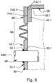
- the first connection system 36 comprises a first closure plate 42.1 closing the first end 38.1 of the tubular interface 38 as well as a second closure plate 42.1. closure 42.2 closing the second end 38.2 of the tubular interface 38.
- the tubular interface 38 comprises a first collar 44.1 at its first end 38.1 as well as a second collar 44.2 at its second end 38.2, each of the first and second collars 44.1, 44.2 having a contact face F44.1, F44.2, positioned in a transverse plane perpendicular to the axis of revolution A38, against which the corresponding closure plate 42.1, 42.1 is pressed.
- Each of the first and second closure plates 42.1, 42.2 is in the form of a disk and comprises at least one connection zone 46 connected, directly or indirectly, to the external or internal enclosure 32, 34. At the connection zones 46, each closure plate 42.1, 42.2 is pressed against the contact face F44.1, F44.2 of the corresponding first or second collar 44.1, 44.2 and connected to the latter by connecting elements.
- the connection zones 46 of the first and second closure plates 42.1, 42.2 are rigid. According to one configuration, each connection zone 46 is in the form of a crown.
- Each of the first and second closure plates 42.1, 42.2 comprises a first face F42.1, F42.2 configured to be pressed against the contact face F44.1, F44.2 of the corresponding first or second collar 44.1, 44.2 as well as a second face F42.1', F42.2' opposite the first face F42.1, F42.2.
- Each of the first and second closure plates 42.1, 42.2 has an axial direction DA substantially perpendicular to the first face F42.1, F42.2.
- the first and second closure plates 42.1, 42.2 When attached to the tubular interface 38, the first and second closure plates 42.1, 42.2 are substantially parallel to each other and perpendicular to the longitudinal direction.
- the axial direction DA is parallel to the longitudinal direction.
- the tank 30 comprises at least one conduit 48 which passes through the first and second closing plates 42.1, 42.2 and has a first end 48.1 opening outside the external enclosure 32 as well as a second end 48.2 opening into the internal enclosure 34.
- the first closure plate 42.1 comprises a first orifice 50.1 to allow the conduit 48 to pass through said first closure plate 42.1 as well that a first connection zone 52.1 which surrounds the first orifice 50.1 and comprises a first connection 54.1 connecting the conduit 48 and the first closing plate 42.1.
- each conduit 48 has an axis of revolution A48 parallel to the axial direction DA.
- the second closure plate 42.2 comprises a second orifice 50.2 to allow the conduit 48 to pass through said second closure plate 42.2 as well as a second connection zone 52.2 which surrounds the second orifice 50.2 and comprises a second connection 54.2 connecting the conduit 48 and the second closure plate 42.2.
- each conduit 48 has an axis of revolution A48 parallel to the axial direction DA.
- the first and second connections 54.1, 54.2 are rigid connections. Consequently, the first and second connection zones 52.1, 52.2 are substantially rigid.
- Each of the first and second connections 54.1, 54.2 is a sealed connection ensuring a fluid seal between the conduit 48 and the first or second closure plate 42.1, 42.2.
- each of the first and second connections 54.1, 54.2 comprises at least one weld bead surrounding the conduit 48 and ensuring a sealed connection between the latter and the closure plate 42.1, 42.2.
- the invention is not limited to this embodiment for the first and second rigid connections 54.1, 54.2.
- the first or second connection 54.1, 54.2 could be in the form of a flange.
- At least one wall 56 among the first and second closure plates 42.1, 42.2 comprises at least one deformable zone 58 interposed between the connection zone 46 and the first or second connection zone 52.1, 52.2 and configured to allow the first or second connection zone 52.1, 52.2 to move relative to the connection zone 46 in the axial direction DA.
- the deformable zone 58 is configured to deform elastically. Outside the deformable zones 58, each of the first and second faces F42.1, F42.2, F44.1', F44.2' of the first and second closure plates 42.1, 42.2 is located in a transverse plane perpendicular to the axial direction DA while in each deformable zone, it is offset in the axial direction relative to this transverse plane.
- the wall 56 comprises, for each connecting zone 52.1, 52.2, a deformable zone 58 surrounding the connecting zone 52.1, 52.2.
- the wall 56 comprises a deformable zone 58 surrounding several connecting zones 52.1, 52.2.
- each deformable zone 58 describes a circle. According to one configuration, the deformable zone 58 and the connection zone 46 are concentric and the deformable zone 58 surrounds all the connection zones 52.1, 52.2.
- the deformable zone 58 comprises at least one corrugation which describes a circle. According to one arrangement, the deformable zone 58 comprises several concentric corrugations forming a bellows.
- the wall 56 has a first thickness outside the deformable zone(s) 58 as well as a second thickness less than the first thickness in each deformable zone 58.
- only one wall 56 among the first and second closing plates 42.1, 42.2 comprises at least one deformable zone 58.
- each of the first and second closing plates 42.1, 42.2 comprises at least one deformable zone 58.
- the first and second closing plates 42.1, 42.2 are obtained by stamping.
- the outer enclosure 34 and the first closure plate 42.1 are in contact with an environment at room temperature while the inner enclosure 34, the second closure plate 42.2 and the section of the conduit 48 located in the inner enclosure 34 are in contact with a fluid at a cryogenic temperature, significantly lower than the room temperature.
- This temperature difference causes a deformation of at least one element, among the outer and inner enclosures 32, 34, the conduit 48 and the first and second closure plates 42.1, 42.2, which tends to modify the spacing between the first and second closure plates 42.1, 42.2 at the first and second orifices 50.1, 50.2.
- connection zone 52.1, 52.2 surrounding each conduit 48 can move in the axial direction DA relative to the tubular interface 38 and compensate for the dimensional variation between the first and second closure plates 42.1, 42.2, which makes it possible to limit the stresses on the first and second connections 54.1, 54.2 and to reduce the risks of damage to said first and second connections 54.1, 54.2.
- this temperature difference causes different deformations of the tubular interface 38 and of at least one of the first and second closure plates 42.1, 42.2.
- the differences in deformation are all the more significant as the materials of the tubular interface and the closure plates are different, for example when the tubular interface 38 is made of a composite material and the closure plates are metallic.
- the fact that a closure plate 42.1, 42.2 comprises at least one deformable zone 58 allows radial deformations of said closure plate, which makes it possible to compensate for the differences in deformation between this closure plate and the tubular interface.
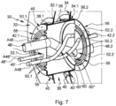
- the tank 30 comprises several conduits 48, 48', 48" which pass through the first and second closing plates 42.1, 42.2.
- each 48, 48', 48" conduit is straight
- each conduit 48, 48', 48" comprises an intermediate section 60 located between the first and second closure plates 42.1, 42.2.
- the intermediate section 60 has a curved axis A48 and an excess length between said first and second closure plates 42.1, 42.2.
- This excess length of the intermediate section 60 of the conduit 48 makes it possible to compensate for the dimensional variation between the first and second closure plates 42.1, 42.2, to limit the stresses on the first and second connections 54.1, 54.2 and to reduce the risks of damage to said first and second connections 54.1, 54.2.
- the axis A48 of the intermediate section 60 follows a trajectory in the form of a circular helix at least between the first and second closure plates 42.1, 42.2.
- the first and second closure plates 42.1, 42.2 are substantially parallel to each other and angularly offset by approximately 180°. Consequently, if the first orifice 50.1 of the first closure plate 42.1 crossed by a conduit 48 is located at 6 o'clock, then the second orifice 50.2 of the second closure plate 42.1 crossed by the same conduit 48 is located at 12 o'clock.
- each of them comprises an intermediate section 60, 60', 60" which has a curved axis A48, A48', A48". All the intermediate sections 60, 60', 60" follow circular helix-shaped trajectories having approximately the same helix axis, at least between the first and second closing plates 42.1, 42.2.
- the invention is not limited to the embodiments described above.
- the first and second closure plates 42.1, 42.2 could be positioned respectively in line with the walls of the external and internal enclosures 32, 34.
- the tank 30 comprises a first wall 42.1 connected to the external enclosure 32 at at least one connection zone 46, a second wall 42.2 connected to the internal enclosure 34 at at least one connection zone 46 as well as at least one conduit 48 passing through the first and second walls 42.1, 42.2.
- the first and second walls 42.1, 42.2 respectively comprise first and second orifices 50.1, 50.2 to allow the conduit 48 to pass through the first and second walls 42.1, 42.2.
- the tank 30 comprises, for each conduit 48 and each of the first and second walls 42.1, 42.2, a connection zone 52.1, 52.2 which surrounds the first or second orifice 50.1, 50.2 and comprises a connection 54.1, 54.2 connecting the conduit 48 and the first or second wall 42.1, 42.2.
Landscapes
- Engineering & Computer Science (AREA)
- Mechanical Engineering (AREA)
- General Engineering & Computer Science (AREA)
- Filling Or Discharging Of Gas Storage Vessels (AREA)
- Joints Allowing Movement (AREA)
- Catching Or Destruction (AREA)
- Supply Devices, Intensifiers, Converters, And Telemotors (AREA)
Applications Claiming Priority (1)
| Application Number | Priority Date | Filing Date | Title |
|---|---|---|---|
| FR2304309A FR3148281A1 (fr) | 2023-04-28 | 2023-04-28 | Réservoir comprenant des enceintes interne et externe ainsi qu’au moins un conduit traversant au moins une plaque de fermeture déformable |
Publications (2)
| Publication Number | Publication Date |
|---|---|
| EP4462012A1 true EP4462012A1 (de) | 2024-11-13 |
| EP4462012B1 EP4462012B1 (de) | 2025-06-18 |
Family
ID=87554985
Family Applications (1)
| Application Number | Title | Priority Date | Filing Date |
|---|---|---|---|
| EP24167914.1A Active EP4462012B1 (de) | 2023-04-28 | 2024-03-29 | Tank mit innen- und aussenräumen sowie mindestens einer leitung, die mindestens eine verformbare verschlussplatte durchquert |
Country Status (3)
| Country | Link |
|---|---|
| US (1) | US20240360961A1 (de) |
| EP (1) | EP4462012B1 (de) |
| FR (1) | FR3148281A1 (de) |
Citations (5)
| Publication number | Priority date | Publication date | Assignee | Title |
|---|---|---|---|---|
| SU1502897A1 (ru) * | 1986-04-30 | 1989-08-23 | Особое конструкторско-технологическое бюро Физико-технического института низких температур АН УССР | Криогенный сосуд дл транспортировани |
| NL8801044A (nl) * | 1988-04-21 | 1989-11-16 | Kelpa Cryogenics B V | Transporttank voor bij lage temperatuur vloeibaar gemaakt gas. |
| US7344045B2 (en) * | 2003-09-23 | 2008-03-18 | Westport Power Inc. | Container for holding a cryogenic fluid |
| US20170130900A1 (en) * | 2014-05-23 | 2017-05-11 | Westport Power Inc. | Bracketed support for a double walled cryogenic storage vessel |
| US20220042651A1 (en) * | 2018-12-11 | 2022-02-10 | L'Air Liquide, Societe Anonyme pour I'Etude et I'Exploitation des Precedes Georges Claude | Support device and storage container for liquefied gas |
Family Cites Families (6)
| Publication number | Priority date | Publication date | Assignee | Title |
|---|---|---|---|---|
| JP5782305B2 (ja) * | 2011-06-24 | 2015-09-24 | ジャパンマリンユナイテッド株式会社 | 液化ガスタンク |
| KR102021038B1 (ko) * | 2018-01-15 | 2019-09-11 | 하이리움산업(주) | 저장탱크 |
| US20230321607A1 (en) * | 2020-08-17 | 2023-10-12 | InnoSpire Technologies GmbH | Monolithic Membrane Filters |
| KR20220134282A (ko) * | 2021-03-26 | 2022-10-05 | 주식회사래티스테크놀로지 | 수축 변위 흡수가 가능한 맨홀 구조 및 이를 포함하는 이중 탱크 |
| FR3127273A1 (fr) * | 2021-11-25 | 2023-03-24 | Airbus Operations Sas | Reservoir cryogenique ameliore pour aeronef et aeronef comprenant un tel reservoir. |
| CN114857487A (zh) * | 2022-05-25 | 2022-08-05 | 中太(苏州)氢能源科技有限公司 | 一种锥形回型迷宫结构支撑结构 |
-
2023
- 2023-04-28 FR FR2304309A patent/FR3148281A1/fr not_active Withdrawn
-
2024
- 2024-03-29 EP EP24167914.1A patent/EP4462012B1/de active Active
- 2024-04-24 US US18/644,955 patent/US20240360961A1/en active Pending
Patent Citations (5)
| Publication number | Priority date | Publication date | Assignee | Title |
|---|---|---|---|---|
| SU1502897A1 (ru) * | 1986-04-30 | 1989-08-23 | Особое конструкторско-технологическое бюро Физико-технического института низких температур АН УССР | Криогенный сосуд дл транспортировани |
| NL8801044A (nl) * | 1988-04-21 | 1989-11-16 | Kelpa Cryogenics B V | Transporttank voor bij lage temperatuur vloeibaar gemaakt gas. |
| US7344045B2 (en) * | 2003-09-23 | 2008-03-18 | Westport Power Inc. | Container for holding a cryogenic fluid |
| US20170130900A1 (en) * | 2014-05-23 | 2017-05-11 | Westport Power Inc. | Bracketed support for a double walled cryogenic storage vessel |
| US20220042651A1 (en) * | 2018-12-11 | 2022-02-10 | L'Air Liquide, Societe Anonyme pour I'Etude et I'Exploitation des Precedes Georges Claude | Support device and storage container for liquefied gas |
Also Published As
| Publication number | Publication date |
|---|---|
| US20240360961A1 (en) | 2024-10-31 |
| FR3148281A1 (fr) | 2024-11-01 |
| EP4462012B1 (de) | 2025-06-18 |
Similar Documents
| Publication | Publication Date | Title |
|---|---|---|
| EP4215791B1 (de) | Vorrichtung zum verbinden zweier doppelwandleitungen und wasserstoffleitung mit dieser verbindungsvorrichtung | |
| FR3024224A1 (fr) | Echangeur thermique a plaques avec renforts structurels pour turbomoteur | |
| EP3301344B1 (de) | Anschlussvorrichtung, die eine flexible muffe zum sammeln einer flüssigkeit im falle eines lecks oder aussickerns umfasst | |
| EP0376772A1 (de) | Bewegliche Rohrverbindung, insbesondere für Auspuffrohre an Kraftfahrzeugen | |
| FR2796416A1 (fr) | Perfectionnement a un flexible de decouplage monte dans une ligne d'echappement d'un moteur de vehicule automobile | |
| EP4462012B1 (de) | Tank mit innen- und aussenräumen sowie mindestens einer leitung, die mindestens eine verformbare verschlussplatte durchquert | |
| EP0430731B1 (de) | Gefäss für kryogene Flüssigkeit | |
| EP4455542B1 (de) | Tank mit innen- und aussenräumen sowie mindestens einer leitung, die diese gehäuse durchquert und eine gekrümmte bahn zwischen den gehäusen | |
| EP0702189A1 (de) | Ausdehnungsverbindung für heisse Rohrleitungen | |
| EP4428430B1 (de) | Tank mit innen- und aussenräumen sowie mindestens einem ringförmigen linearen verbindungssystem zur verbindung dieser behälter | |
| EP4455543B1 (de) | Tank mit innen- und aussenräumen sowie mindestens einer zweiteiligen rohrschnittstelle, die den innen- und aussenraum durchquert | |
| EP3814616B1 (de) | Leitvorrichtung in einer brennkammer | |
| WO2020161197A2 (fr) | Elément d'isolation thermique et ensemble comprenant un tel élément | |
| FR2465947A1 (fr) | Boitier pour l'isolation thermique d'appareils ou accessoires montes sur des tuyauteries de transport de fluide | |
| US12181081B2 (en) | Pipe connecting system | |
| FR2471544A1 (fr) | Dispositif de raccordement souple entre deux troncons de conduite de fluide | |
| FR2839135A1 (fr) | Dispositif d'accouplement souple entre deux elements transportant des fluides sous pression | |
| FR3160396A1 (fr) | Réservoir comprenant au moins un système de liaison à lames de jonction périphériques reliant une structure intérieure et une enceinte, aéronef comportant au moins un tel réservoir | |
| EP1611388A1 (de) | Gasdichte dichtung für eine verbindung zwischen zwei leitungen und die dichtung enthaltende verbindung zwischen zwei dichtungen | |
| EP3584488A1 (de) | Kanalisation, die zwei leitungen umfasst, die über ein verbessertes anschlusssystem verbunden sind | |
| WO2008152311A2 (fr) | Dispositif d'isolation d'un collecteur d'echappement | |
| FR2886338A1 (fr) | Collecteur d'echappement a double paroi pour moteur a combustion interne | |
| FR3164770A1 (fr) | Raccord demontable pour tubes cryogeniques a isolation sous vide et procede de raccordement correspondant. | |
| FR2905439A1 (fr) | Joint metallique a insert elastique | |
| WO2015104515A1 (fr) | Moteur borgne a combustion interne avec une etancheite aux gaz améliorée |
Legal Events
| Date | Code | Title | Description |
|---|---|---|---|
| PUAI | Public reference made under article 153(3) epc to a published international application that has entered the european phase |
Free format text: ORIGINAL CODE: 0009012 |
|
| STAA | Information on the status of an ep patent application or granted ep patent |
Free format text: STATUS: REQUEST FOR EXAMINATION WAS MADE |
|
| 17P | Request for examination filed |
Effective date: 20240329 |
|
| AK | Designated contracting states |
Kind code of ref document: A1 Designated state(s): AL AT BE BG CH CY CZ DE DK EE ES FI FR GB GR HR HU IE IS IT LI LT LU LV MC ME MK MT NL NO PL PT RO RS SE SI SK SM TR |
|
| GRAP | Despatch of communication of intention to grant a patent |
Free format text: ORIGINAL CODE: EPIDOSNIGR1 |
|
| STAA | Information on the status of an ep patent application or granted ep patent |
Free format text: STATUS: GRANT OF PATENT IS INTENDED |
|
| INTG | Intention to grant announced |
Effective date: 20250120 |
|
| GRAS | Grant fee paid |
Free format text: ORIGINAL CODE: EPIDOSNIGR3 |
|
| GRAA | (expected) grant |
Free format text: ORIGINAL CODE: 0009210 |
|
| STAA | Information on the status of an ep patent application or granted ep patent |
Free format text: STATUS: THE PATENT HAS BEEN GRANTED |
|
| AK | Designated contracting states |
Kind code of ref document: B1 Designated state(s): AL AT BE BG CH CY CZ DE DK EE ES FI FR GB GR HR HU IE IS IT LI LT LU LV MC ME MK MT NL NO PL PT RO RS SE SI SK SM TR |
|
| REG | Reference to a national code |
Ref country code: GB Ref legal event code: FG4D Free format text: NOT ENGLISH |
|
| REG | Reference to a national code |
Ref country code: CH Ref legal event code: EP |
|
| REG | Reference to a national code |
Ref country code: DE Ref legal event code: R096 Ref document number: 602024000210 Country of ref document: DE |
|
| REG | Reference to a national code |
Ref country code: CH Ref legal event code: EP |
|
| REG | Reference to a national code |
Ref country code: IE Ref legal event code: FG4D Free format text: LANGUAGE OF EP DOCUMENT: FRENCH |
|
| PG25 | Lapsed in a contracting state [announced via postgrant information from national office to epo] |
Ref country code: FI Free format text: LAPSE BECAUSE OF FAILURE TO SUBMIT A TRANSLATION OF THE DESCRIPTION OR TO PAY THE FEE WITHIN THE PRESCRIBED TIME-LIMIT Effective date: 20250618 |
|
| REG | Reference to a national code |
Ref country code: LT Ref legal event code: MG9D |
|
| PG25 | Lapsed in a contracting state [announced via postgrant information from national office to epo] |
Ref country code: GR Free format text: LAPSE BECAUSE OF FAILURE TO SUBMIT A TRANSLATION OF THE DESCRIPTION OR TO PAY THE FEE WITHIN THE PRESCRIBED TIME-LIMIT Effective date: 20250919 Ref country code: NO Free format text: LAPSE BECAUSE OF FAILURE TO SUBMIT A TRANSLATION OF THE DESCRIPTION OR TO PAY THE FEE WITHIN THE PRESCRIBED TIME-LIMIT Effective date: 20250918 |
|
| PG25 | Lapsed in a contracting state [announced via postgrant information from national office to epo] |
Ref country code: BG Free format text: LAPSE BECAUSE OF FAILURE TO SUBMIT A TRANSLATION OF THE DESCRIPTION OR TO PAY THE FEE WITHIN THE PRESCRIBED TIME-LIMIT Effective date: 20250618 |
|
| PG25 | Lapsed in a contracting state [announced via postgrant information from national office to epo] |
Ref country code: HR Free format text: LAPSE BECAUSE OF FAILURE TO SUBMIT A TRANSLATION OF THE DESCRIPTION OR TO PAY THE FEE WITHIN THE PRESCRIBED TIME-LIMIT Effective date: 20250618 |
|
| PG25 | Lapsed in a contracting state [announced via postgrant information from national office to epo] |
Ref country code: RS Free format text: LAPSE BECAUSE OF FAILURE TO SUBMIT A TRANSLATION OF THE DESCRIPTION OR TO PAY THE FEE WITHIN THE PRESCRIBED TIME-LIMIT Effective date: 20250918 |
|
| REG | Reference to a national code |
Ref country code: NL Ref legal event code: MP Effective date: 20250618 |
|
| PG25 | Lapsed in a contracting state [announced via postgrant information from national office to epo] |
Ref country code: LV Free format text: LAPSE BECAUSE OF FAILURE TO SUBMIT A TRANSLATION OF THE DESCRIPTION OR TO PAY THE FEE WITHIN THE PRESCRIBED TIME-LIMIT Effective date: 20250618 |
|
| PG25 | Lapsed in a contracting state [announced via postgrant information from national office to epo] |
Ref country code: NL Free format text: LAPSE BECAUSE OF FAILURE TO SUBMIT A TRANSLATION OF THE DESCRIPTION OR TO PAY THE FEE WITHIN THE PRESCRIBED TIME-LIMIT Effective date: 20250618 |
|
| PG25 | Lapsed in a contracting state [announced via postgrant information from national office to epo] |
Ref country code: PT Free format text: LAPSE BECAUSE OF FAILURE TO SUBMIT A TRANSLATION OF THE DESCRIPTION OR TO PAY THE FEE WITHIN THE PRESCRIBED TIME-LIMIT Effective date: 20251020 |
|
| REG | Reference to a national code |
Ref country code: AT Ref legal event code: MK05 Ref document number: 1804465 Country of ref document: AT Kind code of ref document: T Effective date: 20250618 |
|
| PG25 | Lapsed in a contracting state [announced via postgrant information from national office to epo] |
Ref country code: IS Free format text: LAPSE BECAUSE OF FAILURE TO SUBMIT A TRANSLATION OF THE DESCRIPTION OR TO PAY THE FEE WITHIN THE PRESCRIBED TIME-LIMIT Effective date: 20251018 |
|
| PG25 | Lapsed in a contracting state [announced via postgrant information from national office to epo] |
Ref country code: AT Free format text: LAPSE BECAUSE OF FAILURE TO SUBMIT A TRANSLATION OF THE DESCRIPTION OR TO PAY THE FEE WITHIN THE PRESCRIBED TIME-LIMIT Effective date: 20250618 Ref country code: SM Free format text: LAPSE BECAUSE OF FAILURE TO SUBMIT A TRANSLATION OF THE DESCRIPTION OR TO PAY THE FEE WITHIN THE PRESCRIBED TIME-LIMIT Effective date: 20250618 |
|
| PG25 | Lapsed in a contracting state [announced via postgrant information from national office to epo] |
Ref country code: CZ Free format text: LAPSE BECAUSE OF FAILURE TO SUBMIT A TRANSLATION OF THE DESCRIPTION OR TO PAY THE FEE WITHIN THE PRESCRIBED TIME-LIMIT Effective date: 20250618 |
|
| PG25 | Lapsed in a contracting state [announced via postgrant information from national office to epo] |
Ref country code: PL Free format text: LAPSE BECAUSE OF FAILURE TO SUBMIT A TRANSLATION OF THE DESCRIPTION OR TO PAY THE FEE WITHIN THE PRESCRIBED TIME-LIMIT Effective date: 20250618 |
|
| PG25 | Lapsed in a contracting state [announced via postgrant information from national office to epo] |
Ref country code: EE Free format text: LAPSE BECAUSE OF FAILURE TO SUBMIT A TRANSLATION OF THE DESCRIPTION OR TO PAY THE FEE WITHIN THE PRESCRIBED TIME-LIMIT Effective date: 20250618 |
|
| PG25 | Lapsed in a contracting state [announced via postgrant information from national office to epo] |
Ref country code: SK Free format text: LAPSE BECAUSE OF FAILURE TO SUBMIT A TRANSLATION OF THE DESCRIPTION OR TO PAY THE FEE WITHIN THE PRESCRIBED TIME-LIMIT Effective date: 20250618 |
|
| PG25 | Lapsed in a contracting state [announced via postgrant information from national office to epo] |
Ref country code: ES Free format text: LAPSE BECAUSE OF FAILURE TO SUBMIT A TRANSLATION OF THE DESCRIPTION OR TO PAY THE FEE WITHIN THE PRESCRIBED TIME-LIMIT Effective date: 20250618 |