EP4462009A1 - Treibstofftank für flüssigtreibstoff und verfahren zum betrieb dieses treibstofftanks - Google Patents
Treibstofftank für flüssigtreibstoff und verfahren zum betrieb dieses treibstofftanks Download PDFInfo
- Publication number
- EP4462009A1 EP4462009A1 EP24170769.4A EP24170769A EP4462009A1 EP 4462009 A1 EP4462009 A1 EP 4462009A1 EP 24170769 A EP24170769 A EP 24170769A EP 4462009 A1 EP4462009 A1 EP 4462009A1
- Authority
- EP
- European Patent Office
- Prior art keywords
- compartment
- fuel tank
- ring
- liquid fuel
- fuel
- Prior art date
- Legal status (The legal status is an assumption and is not a legal conclusion. Google has not performed a legal analysis and makes no representation as to the accuracy of the status listed.)
- Pending
Links
Images


Classifications
-
- F—MECHANICAL ENGINEERING; LIGHTING; HEATING; WEAPONS; BLASTING
- F17—STORING OR DISTRIBUTING GASES OR LIQUIDS
- F17C—VESSELS FOR CONTAINING OR STORING COMPRESSED, LIQUEFIED OR SOLIDIFIED GASES; FIXED-CAPACITY GAS-HOLDERS; FILLING VESSELS WITH, OR DISCHARGING FROM VESSELS, COMPRESSED, LIQUEFIED, OR SOLIDIFIED GASES
- F17C3/00—Vessels not under pressure
-
- B—PERFORMING OPERATIONS; TRANSPORTING
- B64—AIRCRAFT; AVIATION; COSMONAUTICS
- B64G—COSMONAUTICS; VEHICLES OR EQUIPMENT THEREFOR
- B64G1/00—Cosmonautic vehicles
- B64G1/22—Parts of, or equipment specially adapted for fitting in or to, cosmonautic vehicles
- B64G1/40—Arrangements or adaptations of propulsion systems
- B64G1/402—Propellant tanks; Feeding propellants
- B64G1/4021—Tank construction; Details thereof
-
- F—MECHANICAL ENGINEERING; LIGHTING; HEATING; WEAPONS; BLASTING
- F17—STORING OR DISTRIBUTING GASES OR LIQUIDS
- F17C—VESSELS FOR CONTAINING OR STORING COMPRESSED, LIQUEFIED OR SOLIDIFIED GASES; FIXED-CAPACITY GAS-HOLDERS; FILLING VESSELS WITH, OR DISCHARGING FROM VESSELS, COMPRESSED, LIQUEFIED, OR SOLIDIFIED GASES
- F17C9/00—Methods or apparatus for discharging liquefied or solidified gases from vessels not under pressure
-
- F—MECHANICAL ENGINEERING; LIGHTING; HEATING; WEAPONS; BLASTING
- F17—STORING OR DISTRIBUTING GASES OR LIQUIDS
- F17C—VESSELS FOR CONTAINING OR STORING COMPRESSED, LIQUEFIED OR SOLIDIFIED GASES; FIXED-CAPACITY GAS-HOLDERS; FILLING VESSELS WITH, OR DISCHARGING FROM VESSELS, COMPRESSED, LIQUEFIED, OR SOLIDIFIED GASES
- F17C2201/00—Vessel construction, in particular geometry, arrangement or size
- F17C2201/01—Shape
- F17C2201/0128—Shape spherical or elliptical
-
- F—MECHANICAL ENGINEERING; LIGHTING; HEATING; WEAPONS; BLASTING
- F17—STORING OR DISTRIBUTING GASES OR LIQUIDS
- F17C—VESSELS FOR CONTAINING OR STORING COMPRESSED, LIQUEFIED OR SOLIDIFIED GASES; FIXED-CAPACITY GAS-HOLDERS; FILLING VESSELS WITH, OR DISCHARGING FROM VESSELS, COMPRESSED, LIQUEFIED, OR SOLIDIFIED GASES
- F17C2201/00—Vessel construction, in particular geometry, arrangement or size
- F17C2201/01—Shape
- F17C2201/0147—Shape complex
- F17C2201/0166—Shape complex divided in several chambers
-
- F—MECHANICAL ENGINEERING; LIGHTING; HEATING; WEAPONS; BLASTING
- F17—STORING OR DISTRIBUTING GASES OR LIQUIDS
- F17C—VESSELS FOR CONTAINING OR STORING COMPRESSED, LIQUEFIED OR SOLIDIFIED GASES; FIXED-CAPACITY GAS-HOLDERS; FILLING VESSELS WITH, OR DISCHARGING FROM VESSELS, COMPRESSED, LIQUEFIED, OR SOLIDIFIED GASES
- F17C2201/00—Vessel construction, in particular geometry, arrangement or size
- F17C2201/01—Shape
- F17C2201/0147—Shape complex
- F17C2201/0171—Shape complex comprising a communication hole between chambers
-
- F—MECHANICAL ENGINEERING; LIGHTING; HEATING; WEAPONS; BLASTING
- F17—STORING OR DISTRIBUTING GASES OR LIQUIDS
- F17C—VESSELS FOR CONTAINING OR STORING COMPRESSED, LIQUEFIED OR SOLIDIFIED GASES; FIXED-CAPACITY GAS-HOLDERS; FILLING VESSELS WITH, OR DISCHARGING FROM VESSELS, COMPRESSED, LIQUEFIED, OR SOLIDIFIED GASES
- F17C2201/00—Vessel construction, in particular geometry, arrangement or size
- F17C2201/05—Size
- F17C2201/052—Size large (>1000 m3)
-
- F—MECHANICAL ENGINEERING; LIGHTING; HEATING; WEAPONS; BLASTING
- F17—STORING OR DISTRIBUTING GASES OR LIQUIDS
- F17C—VESSELS FOR CONTAINING OR STORING COMPRESSED, LIQUEFIED OR SOLIDIFIED GASES; FIXED-CAPACITY GAS-HOLDERS; FILLING VESSELS WITH, OR DISCHARGING FROM VESSELS, COMPRESSED, LIQUEFIED, OR SOLIDIFIED GASES
- F17C2201/00—Vessel construction, in particular geometry, arrangement or size
- F17C2201/05—Size
- F17C2201/054—Size medium (>1 m3)
-
- F—MECHANICAL ENGINEERING; LIGHTING; HEATING; WEAPONS; BLASTING
- F17—STORING OR DISTRIBUTING GASES OR LIQUIDS
- F17C—VESSELS FOR CONTAINING OR STORING COMPRESSED, LIQUEFIED OR SOLIDIFIED GASES; FIXED-CAPACITY GAS-HOLDERS; FILLING VESSELS WITH, OR DISCHARGING FROM VESSELS, COMPRESSED, LIQUEFIED, OR SOLIDIFIED GASES
- F17C2203/00—Vessel construction, in particular walls or details thereof
- F17C2203/06—Materials for walls or layers thereof; Properties or structures of walls or their materials
- F17C2203/0634—Materials for walls or layers thereof
- F17C2203/0658—Synthetics
- F17C2203/0663—Synthetics in form of fibers or filaments
-
- F—MECHANICAL ENGINEERING; LIGHTING; HEATING; WEAPONS; BLASTING
- F17—STORING OR DISTRIBUTING GASES OR LIQUIDS
- F17C—VESSELS FOR CONTAINING OR STORING COMPRESSED, LIQUEFIED OR SOLIDIFIED GASES; FIXED-CAPACITY GAS-HOLDERS; FILLING VESSELS WITH, OR DISCHARGING FROM VESSELS, COMPRESSED, LIQUEFIED, OR SOLIDIFIED GASES
- F17C2205/00—Vessel construction, in particular mounting arrangements, attachments or identifications means
- F17C2205/03—Fluid connections, filters, valves, closure means or other attachments
- F17C2205/0302—Fittings, valves, filters, or components in connection with the gas storage device
- F17C2205/0311—Closure means
-
- F—MECHANICAL ENGINEERING; LIGHTING; HEATING; WEAPONS; BLASTING
- F17—STORING OR DISTRIBUTING GASES OR LIQUIDS
- F17C—VESSELS FOR CONTAINING OR STORING COMPRESSED, LIQUEFIED OR SOLIDIFIED GASES; FIXED-CAPACITY GAS-HOLDERS; FILLING VESSELS WITH, OR DISCHARGING FROM VESSELS, COMPRESSED, LIQUEFIED, OR SOLIDIFIED GASES
- F17C2205/00—Vessel construction, in particular mounting arrangements, attachments or identifications means
- F17C2205/03—Fluid connections, filters, valves, closure means or other attachments
- F17C2205/0302—Fittings, valves, filters, or components in connection with the gas storage device
- F17C2205/0379—Manholes or access openings for human beings
-
- F—MECHANICAL ENGINEERING; LIGHTING; HEATING; WEAPONS; BLASTING
- F17—STORING OR DISTRIBUTING GASES OR LIQUIDS
- F17C—VESSELS FOR CONTAINING OR STORING COMPRESSED, LIQUEFIED OR SOLIDIFIED GASES; FIXED-CAPACITY GAS-HOLDERS; FILLING VESSELS WITH, OR DISCHARGING FROM VESSELS, COMPRESSED, LIQUEFIED, OR SOLIDIFIED GASES
- F17C2205/00—Vessel construction, in particular mounting arrangements, attachments or identifications means
- F17C2205/03—Fluid connections, filters, valves, closure means or other attachments
- F17C2205/0388—Arrangement of valves, regulators, filters
- F17C2205/0391—Arrangement of valves, regulators, filters inside the pressure vessel
-
- F—MECHANICAL ENGINEERING; LIGHTING; HEATING; WEAPONS; BLASTING
- F17—STORING OR DISTRIBUTING GASES OR LIQUIDS
- F17C—VESSELS FOR CONTAINING OR STORING COMPRESSED, LIQUEFIED OR SOLIDIFIED GASES; FIXED-CAPACITY GAS-HOLDERS; FILLING VESSELS WITH, OR DISCHARGING FROM VESSELS, COMPRESSED, LIQUEFIED, OR SOLIDIFIED GASES
- F17C2223/00—Handled fluid before transfer, i.e. state of fluid when stored in the vessel or before transfer from the vessel
- F17C2223/01—Handled fluid before transfer, i.e. state of fluid when stored in the vessel or before transfer from the vessel characterised by the phase
- F17C2223/0146—Two-phase
- F17C2223/0153—Liquefied gas, e.g. LPG, GPL
- F17C2223/0161—Liquefied gas, e.g. LPG, GPL cryogenic, e.g. LNG, GNL, PLNG
-
- F—MECHANICAL ENGINEERING; LIGHTING; HEATING; WEAPONS; BLASTING
- F17—STORING OR DISTRIBUTING GASES OR LIQUIDS
- F17C—VESSELS FOR CONTAINING OR STORING COMPRESSED, LIQUEFIED OR SOLIDIFIED GASES; FIXED-CAPACITY GAS-HOLDERS; FILLING VESSELS WITH, OR DISCHARGING FROM VESSELS, COMPRESSED, LIQUEFIED, OR SOLIDIFIED GASES
- F17C2223/00—Handled fluid before transfer, i.e. state of fluid when stored in the vessel or before transfer from the vessel
- F17C2223/03—Handled fluid before transfer, i.e. state of fluid when stored in the vessel or before transfer from the vessel characterised by the pressure level
- F17C2223/033—Small pressure, e.g. for liquefied gas
-
- F—MECHANICAL ENGINEERING; LIGHTING; HEATING; WEAPONS; BLASTING
- F17—STORING OR DISTRIBUTING GASES OR LIQUIDS
- F17C—VESSELS FOR CONTAINING OR STORING COMPRESSED, LIQUEFIED OR SOLIDIFIED GASES; FIXED-CAPACITY GAS-HOLDERS; FILLING VESSELS WITH, OR DISCHARGING FROM VESSELS, COMPRESSED, LIQUEFIED, OR SOLIDIFIED GASES
- F17C2223/00—Handled fluid before transfer, i.e. state of fluid when stored in the vessel or before transfer from the vessel
- F17C2223/04—Handled fluid before transfer, i.e. state of fluid when stored in the vessel or before transfer from the vessel characterised by other properties of handled fluid before transfer
- F17C2223/042—Localisation of the removal point
- F17C2223/046—Localisation of the removal point in the liquid
-
- F—MECHANICAL ENGINEERING; LIGHTING; HEATING; WEAPONS; BLASTING
- F17—STORING OR DISTRIBUTING GASES OR LIQUIDS
- F17C—VESSELS FOR CONTAINING OR STORING COMPRESSED, LIQUEFIED OR SOLIDIFIED GASES; FIXED-CAPACITY GAS-HOLDERS; FILLING VESSELS WITH, OR DISCHARGING FROM VESSELS, COMPRESSED, LIQUEFIED, OR SOLIDIFIED GASES
- F17C2227/00—Transfer of fluids, i.e. method or means for transferring the fluid; Heat exchange with the fluid
- F17C2227/04—Methods for emptying or filling
-
- F—MECHANICAL ENGINEERING; LIGHTING; HEATING; WEAPONS; BLASTING
- F17—STORING OR DISTRIBUTING GASES OR LIQUIDS
- F17C—VESSELS FOR CONTAINING OR STORING COMPRESSED, LIQUEFIED OR SOLIDIFIED GASES; FIXED-CAPACITY GAS-HOLDERS; FILLING VESSELS WITH, OR DISCHARGING FROM VESSELS, COMPRESSED, LIQUEFIED, OR SOLIDIFIED GASES
- F17C2260/00—Purposes of gas storage and gas handling
- F17C2260/01—Improving mechanical properties or manufacturing
- F17C2260/016—Preventing slosh
-
- F—MECHANICAL ENGINEERING; LIGHTING; HEATING; WEAPONS; BLASTING
- F17—STORING OR DISTRIBUTING GASES OR LIQUIDS
- F17C—VESSELS FOR CONTAINING OR STORING COMPRESSED, LIQUEFIED OR SOLIDIFIED GASES; FIXED-CAPACITY GAS-HOLDERS; FILLING VESSELS WITH, OR DISCHARGING FROM VESSELS, COMPRESSED, LIQUEFIED, OR SOLIDIFIED GASES
- F17C2265/00—Effects achieved by gas storage or gas handling
- F17C2265/06—Fluid distribution
- F17C2265/066—Fluid distribution for feeding engines for propulsion
-
- F—MECHANICAL ENGINEERING; LIGHTING; HEATING; WEAPONS; BLASTING
- F17—STORING OR DISTRIBUTING GASES OR LIQUIDS
- F17C—VESSELS FOR CONTAINING OR STORING COMPRESSED, LIQUEFIED OR SOLIDIFIED GASES; FIXED-CAPACITY GAS-HOLDERS; FILLING VESSELS WITH, OR DISCHARGING FROM VESSELS, COMPRESSED, LIQUEFIED, OR SOLIDIFIED GASES
- F17C2270/00—Applications
- F17C2270/01—Applications for fluid transport or storage
- F17C2270/0186—Applications for fluid transport or storage in the air or in space
- F17C2270/0197—Rockets
Definitions
- the invention relates to a fuel tank for liquid fuel according to the preamble of claim 1 and a method for operating this fuel tank according to the preamble of claim 9.
- Such fuel tanks are used in space flight.
- the fuel management for cryogenic and storable upper stages and also reusable lower stages is the central focus of expanding the functionality of the carrier systems and enabling missions that were previously not possible.
- the conditioning consists in the liquid fuel being at the tank outlet, having an appropriate temperature at a given minimum pressure and having a limited number and size of bubbles.
- the supercooled cryogenic liquid fuel is deposited on the bottom of the tank. Then either the ballistic phase or the payload release begins, in which where a portion of the liquid fuel reaches the upper tank segments, where this portion of the liquid fuel is heated by the pressurizing gas supplied to the tank via the upper void space gas supply and the external heat bridges.
- cryogenic or storable liquid fuel moves through the warm void gas and along the tank walls to the upper tank segment, whereby the void gas and the tank wall are cooled by the liquid fuel and the heat migrates into the liquid fuel or boil-off, a continuous evaporation of the liquid fuel, occurs.
- Sloshing is also a problem of fuel management and causes problems with the stabilization of the liquid fuel.
- Membrane tanks are known for storable liquid fuels, but are currently not compatible with cryogenic liquid fuels.
- the invention is therefore based on the object of developing a fuel tank for liquid fuel and a method for operating this fuel tank, in which after the first propulsion phase, in the ballistic phase and when a payload is released on the one hand, the distribution of liquid fuel in the fuel tank is prevented and, on the other hand, the mixing of liquid fuel and the hot pressurization gas produced in the first propulsion phase is reduced.
- a fuel tank for liquid fuel according to the invention has a tank outlet and a void gas supply, each of which passes through a tank wall in one area.
- an interior of the fuel tank is divided into two compartments by a compartment divider with a compartment gate, one of which is assigned to the tank outlet and the other compartment to the void gas supply.
- the two compartments can be fluidically connected to one another or separated from one another by a compartment gate.
- the compartment divider has an outer ring connected to the tank wall and an inner ring supporting the compartment gate, the outer ring and the inner ring being connected to one another by means of a support structure and this support structure supporting a plate assembly.
- the compartment divider can thus be divided into a large number of identical segments, each segment holding one plate of the plate assembly.
- the plates are thus preferably "pie-shaped" and mechanically or materially connected to the support structure.
- Such a compartment divider is characterized by high structural stability and can be constructed in a modular manner.
- the panels of the panel composite are made of the same material or a material that has the same or similar thermal expansion behavior as the material of the tank shell or tank wall. This measure can reduce thermal stresses.
- the tank shell is made of a fiber-reinforced composite plastic
- the panel composite is made of the same or similar composite plastic.
- fibers are carbon fibers and glass fiber.
- composite plastics are CFRP (carbon fiber reinforced plastics) and GFRP (glass fiber reinforced plastics).
- Alternative fibers are, for example, aramid fibers.
- the panel composite can also be designed as a CFRP-GFRP composite.
- the stability of the support structure can be further increased if the inner ring is connected to the lower tank cover by means of an inner tank structure.
- the compartment door has a lifting disc with a diffuser ring attached to the lifting disc.
- This measure means that, on the one hand, when the compartment door is open, the two compartments are connected to each other via the diffuser ring. On the other hand, when the compartment door is closed, the two compartments are separated from each other by the lifting disc.
- the holder is hollow-cylindrical and has an upper diffuser on its outer surface.
- this embodiment provides a second diffuser ring and a sliding ring, which are arranged in such a way that in a middle position of the compartment door, the inner ring closes the second diffuser ring and the sliding ring closes the upper diffuser.
- the flexible compartment separator is arranged in the interior of the fuel tank in such a way that the upper compartment holds the amount of liquid fuel required for the first propulsion phase and the liquid fuel required in the next propulsion phases is in the lower compartment.
- an additional empty space gas supply is arranged in the lower compartment. This measure allows pressure differences between the two compartments to be compensated.
- the void space gas supplies are designed in the form of a diffuser, because this ensures a homogeneous flow of the void space gas into the compartments.
- the compartment door is closed during maneuvers with sloshing movements and when releasing the payload. because it prevents the liquid fuel from spreading across the entire tank wall.
- the new fuel tank for a, preferably but not limited, cryogenic liquid fuel will be explained in more detail using an embodiment example.
- a fuel tank 1 according to the invention for fuels has a tank wall 2 with a manhole 3, wherein a tank outlet 5 is arranged in a manhole cover 4 and a void gas supply 6 is arranged through the tank wall 2.
- the fuel tank 1 is, for example, a fuel tank of a carrier rocket.
- the tank 1 has a circular cross-section (see section AA in Figure 2 ).
- the interior of the fuel tank 1 is divided into a lower compartment 9 and an upper compartment 10 by a compartment divider 7 with a compartment gate 8.
- the compartment separator 7 has an outer ring 11 connected to the tank wall 2 and an inner ring 12 which is connected to the lower tank cover via a bracket 13.
- the outer ring 11 and the inner ring 12 are connected to one another by means of a support structure 14.
- the outer ring 11 has an outer contour that corresponds to the inner wall of the tank in the connection area.
- the inner ring 12 is several times smaller than the outer ring 11 and is arranged concentrically to the outer ring 11.
- the support structure 14 comprises elongated profiles which extend in a star shape between the rings 11, 12 and are firmly connected to them.
- the profiles divide a ring area between the rings 11, 12 into a plurality of equally sized segments.
- the support structure 14 carries a plate assembly 15 (e.g. CFRP-GFRP assembly) which has a large number of individual plates. Each plate is fluid-tight and has an outer contour or surface corresponding to a segment. The plates cover or seal the segments in a fluid-tight manner and are mechanically fixed or glued to the support structure 14, the outer ring 11 and the inner ring 12.
- a plate assembly 15 e.g. CFRP-GFRP assembly
- Each plate is fluid-tight and has an outer contour or surface corresponding to a segment.
- the plates cover or seal the segments in a fluid-tight manner and are mechanically fixed or glued to the support structure 14, the outer ring 11 and the inner ring 12.
- the compartment gate 8 is located in the inner ring 12 and has a lifting disk 16 with a diffuser ring 17.
- the diffuser ring 17 is connected to the lifting disk 16 and has an outer diameter that corresponds to an inner diameter of the compartment gate 8. The diffuser ring 17 thus carries out every movement of the lifting disk 17 or is carried along by the lifting disk 17.
- the compartment gate 8 is nominally opened and allows the liquid fuel or the void gas to flow from the upper compartment 10 to the lower compartment 9 via the diffuser ring 17.
- the diffuser ring 17 ensures optimum distribution of the void gas entering the lower compartment 9 and thus enables suitable pressure equalization between the two compartments 9, 10.
- the lifting disc 16 is lowered in a fluid-tight manner onto the support structure 14, in particular onto the plate assembly 15, and the compartment pipe 8 is thus closed.
- the lifting and Lowering of the lifting disc 16 is carried out via a push rod 22 connected to the lifting disc 16, which engages centrally on the lifting disc 16 on the tank outlet side and is in operative connection with a cylinder piston unit 23 (not numbered).
- the cylinder piston unit 23 can have a compression spring 24 in a spring chamber, by means of which the lifting disc 16 is held in its open position ( Figure 3 ) is held.
- a fluid pressure is fed into a cylinder chamber 26 via a line 25 in such a way that a piston is subjected to a pressure force acting against and overcoming the spring force, so that the compression spring 24 is compressed and the push rod 22 and thus the lifting disk 16 are thereby driven along.
- the control of the required valves of the cylinder piston unit 23 can be carried out electropneumatically, electrohydraulically or mechanically.
- An example of a gas fed into the cylinder chamber 26 via the line 25 to generate the pressure force for closing the compartment door 8 is helium.
- the lifting mechanism of the lifting disk 16 is alternatively designed with a spiral drive as a rotating lowering disk.
- the tank outlet side or lower compartment 9 and the empty gas supply side or upper compartment 10 are completely filled with liquid fuel 19.
- liquid fuel is fed through the tank outlet 5 19 is fed to the lower compartment 8 and the void gas is discharged from the upper compartment 10 via the void gas supply 6.
- the compartment door 8 remains open.
- Liquid fuel 19 is taken from the lower compartment 9 via the tank outlet 5 and the void gas 20 from the upper compartment 10 is fed to the lower compartment 9 via the void gas feed 6.
- the liquid fuel 19 flows from the upper compartment 10 through the diffuser ring 17 into the lower compartment 11.
- the upper compartment 10 is completely filled with void gas 20.
- the lower compartment 9 contains liquid fuel 19 with a small amount of void gas 21 that flowed out of the upper compartment 10 when the fuel was removed.
- the void gas 21 has cooled down to the temperature level of the liquid fuel 19.
- the compartment door 8 is still open.
- the compartment door 8 is closed so that the liquid fuel 19 cannot get into the upper compartment 10.
- the lifting disk 16 with diffuser ring 17 is activated and then closes off the two compartments 9, 10 from each other.
- the high-energy empty space gas 20 is in the upper compartment 10 and the cold liquid fuel 19 is in the lower compartment 9. Due to the selected materials of the plate composite 15, only a small heat exchange by means of convection and radiation takes place from the upper compartment 10 to the lower compartment 9.
- an inert gas or a gas from other sources is supplied to the lower compartment 9 via its own empty space gas supply 18.
- the holder 13 is designed as a hollow-cylindrical holder 27, wherein the lifting disk 16 forms the cover surface of the hollow-cylindrical holder 27 and the manhole 3 with the manhole cover 4 forms the base surface of the hollow-cylindrical holder 27.
- the hollow-cylindrical holder 27 has on its outer surface an upper diffuser 28 and a Figures 11 to 13 shown lower passage opening 32, wherein the lower passage opening 32 in the lower compartment 9 achieves a constant pressure equalization between the interior of the hollow cylindrical holder 27 and the outer space surrounding the outer surface of the hollow cylindrical holder 27.
- a second diffuser ring 29 with a slide ring 30 is also arranged on the lifting disk 16 next to the (first) diffuser ring 17, wherein its dimensioning is such that in an additional middle position of the compartment gate 8, the inner ring 12 closes the second diffuser ring 29 and the slide ring 30 closes the upper diffuser 28.
- the second diffuser ring 29 is thus arranged between the first diffuser ring 17 and the slide ring 30.
- FIG. 8 In the Fig. 8 to 10 The three positions of the compartment door 8 are summarized.
- the two diffuser rings 17, 29 and the upper diffuser 28 are open.
- Fig. 9 only the diffuser ring 17 is open.
- the diffuser ring 29 and the upper diffuser 28, however, are closed, so that the pressure equalization between the interior of the hollow-cylindrical holder 27 and the outside space surrounding the surface of the hollow-cylindrical holder 27 is achieved exclusively via the lower passage opening.
- the diffuser rings 17, 29 and the upper diffuser 28 are closed.
- the lifting device is provided with a double diffuser 17, 29 and the support bracket 27 with an upper passage opening 28 (upper diffuser 28) and a lower passage opening 32.
- the lower compartment 9 is functionally divided into two sub-compartments, namely in relation to the support bracket 27 an inner pressure sub-compartment 9.1 (interior) and an outer storage sub-compartment 9.2 (exterior).
- Figure 12 the first lowering of the lifting device is shown in order to decouple the lower pressure part 9.1 and the storage compartment 9.2 at the top.
- This phase is, for example, the re-pressurization phase, in which the warm pressurization gas from the upper compartment 10 is only fed into the lower pressurization compartment 9.1.
- the free surface for evaporation is significantly smaller than when the pressurization compartment 9.1 is opened to the storage compartment 9.2 in the upper area.
- the Figure 9 shown position not set.
- Figure 13 is shown how the lifting device is completely lowered. All diffuser openings 17, 28, 29 are closed.
- the upper compartment 10 and the lower compartment 9 are fluidically separated from each other.
- Only the pressure compartment 9.1 and the bearing compartment 9.2 are fluidically connected to each other via the lower passage opening 32 or are nominally open to each other.
- the Abteitores 8 is particularly useful during maneuvers with sloshing movements and when releasing the payload, where negative accelerations. This prevents cold liquid fuel from entering the upper compartment 10 and the warm void gas has only minimal contact with the cold liquid fuel.
- the upper compartment 10 is also a gas buffer for a gas attitude control system.
- a fuel tank for a liquid fuel with a tank outlet (5) and an empty space gas supply (6) in that the interior of the fuel tank (1) is divided by a compartment divider (7) with a compartment gate (8) into two compartments (9, 10) which can be fluidically connected to one another or separated from one another via the compartment gate (8), wherein the tank outlet (5) is assigned to one compartment (9) and the empty gas supply (6) is assigned to the other compartment (10), and a method for operating such a fuel tank (1).
Landscapes
- Engineering & Computer Science (AREA)
- Mechanical Engineering (AREA)
- General Engineering & Computer Science (AREA)
- Chemical & Material Sciences (AREA)
- Combustion & Propulsion (AREA)
- Remote Sensing (AREA)
- Aviation & Aerospace Engineering (AREA)
- Filling Or Discharging Of Gas Storage Vessels (AREA)
- Feeding And Controlling Fuel (AREA)
Abstract
Description
- Die Erfindung bezieht sich auf einen Treibstofftank für Flüssigtreibstoff nach dem Oberbegriff des Anspruchs 1 und einem Verfahren zum Betrieb dieses Treibstofftanks nach dem Oberbegriff des Anspruchs 9.
- Derartige Treibstofftanks werden im Weltraumflug eingesetzt.
- Das Treibstoffmanagement für kryogene und lagerfähige Oberstufen und auch wiederverwendbarer Unterstufen steht im zentralen Fokus die Funktionalität der Trägersysteme zu erweitern und Mission zu ermöglichen, die vorher nicht möglich waren.
- Nach der ersten Antriebsphase der Unter- und Oberstufe ist bei kleinen Restmengen an Flüssigtreibstoff und großen Volumen des Treibstofftanks der Flüssigtreibstoff für geeignete Konditionierung einer wiederholten Zündung des Triebwerks schwerer zu kontrollieren. Die Konditionierung besteht darin, dass der Flüssigtreibstoff sich am Tankauslass befindet, eine entsprechende Temperatur bei gegebenen Mindestdruck hat und eine limitierte Anzahl bzw. Größe an Blasen vorweist. Diese drei Bedingungen sind nur schwer im Mikro-Gravitationsflug der sogenannten ballistischen Phase zu erreichen und ferner bei aktiven Manöver wie der Aussetzung von Nutzlasten fast nicht einstellbar.
- Nach der ersten Antriebsphase ist der unterkühlte kryogene Flüssigtreibstoff am unteren Tankboden abgesetzt. Danach beginnt entweder die ballistische Phase oder die Nutzlastaussetzung, bei denen ein Teil des Flüssigtreibstoffs zu den oberen Tanksegmenten gelangt, wo dieser Teil des Flüssigtreibstoffs durch das über die obere Leerraumgasraumzufuhr den Tank zugeführte Bedrückungsgas und den äußeren Wärmebücken erwärmt wird.
- Ähnliche Effekt sind für lagerfähige Flüssigtreibstoffe bekannt, wenn ein warmes Bedrückungsgas erzeugt bzw. benutzt wird und Verdampfung oder Zersetzung des Flüssigtreibstoffs auftritt, wenn dieser in Kontakt mit warmen und/ oder heißen Strukturen oder Gasen kommen.
- Für die Nutzlastaussetzung sind teilweise negative Beschleunigungen gegeben und der kryogene bzw. lagerfähige Flüssigtreibstoff bewegt sich durch das warme Leerraumgas und den Tankwänden entlang zum oberen Tanksegment, wobei das Leerraumgas und die Tankwand von dem Flüssigtreibstoff gekühlt werden und die Wärme in den Flüssigtreibstoff wandert bzw. Boil-off, einem kontinuierlichen Abdampfen des Flüssigtreibstoffs, entsteht.
- Auch die Schwapp-Bewegung ist ein Problem des Treibstoffmanagements und verursacht Probleme der Stabilisierung des Flüssigtreibstoffs.
- Zur Vermeidung der zuvor genannten Probleme sind verschiedene Ansätze bekannt. Passive Treibstoffmanagementgeräte, welche über Kapillarkräfte wirken, können nur einen kleinen Teil lokal behalten (z.B. am Tankauslass), aber nicht den ganzen Rest des Flüssigtreibstoffs und kommen auch bei zu großen Beschleunigungen an ihre Grenzen bzw. sind für lagerfähige Flüssigtreibstoffe gar nicht geeignet. In der ballistischen Phase gibt es die Möglichkeit, den Flüssigtreibstoff mittels konstanten Schubs eines Hilfssystems am Tankboden abzusetzen, wobei aber zum Betrieb dieses Hilfssystems permanent Flüssigtreibstoff benötigt wird. Anderen Strategien in der ballistischen Phase sind die Spin und 3-Achsen-Stabilisierung, welche aber zu einer ähnlichen Problematik nach Beendigung der Phase und der Phase einer wiederholten Zündung des Triebwerks führen. Eine strukturelle Lösung mittels eines geschlossenen Tanksystems hat entsprechende Probleme der integralen Fertigung und kann nicht als Kit betrachtet werden. Der Tank-in-Tank für einen metallischen Tank hat die Herausforderung die System Masse gering zu halten.
- Auch offene Architekturen über das Man-Hole-Cover als Start-Basket, haben Probleme den Flüssigtreibstoff zu speichern und können auch nur einen gewissen Anteil an Flüssigtreibstoff halten, so dass der Rest an Flüssigtreibstoff dann denselben Bedingung im Tank ausgesetzt sein würde, was zu einer ähnlichen Gesamtproblematik der Konditionierung des Flüssigtreibstoffs vor der wiederholten Zündung führt.
- Membran-Tanks sind für lagerfähige Flüssigtreibstoffe bekannt, aber für kryogene Flüssigtreibstoffe aktuell nicht kompatibel.
- Flexible Membrane für das Sammeln des Flüssigtreibstoffs haben teilweise, je nach ihrer Anordnung im Tank, den Nachteil, dass eine vergrößerte Evaporation des Flüssigtreibstoffs aufgrund der Oberfläche und der Wärmebrücken auftritt, so dass auch hier nur ein Teil des Restes des Flüssigtreibstoffs gesammelt werden kann.
- Der Erfindung liegt daher die Aufgabe zu Grunde, ein Treibstofftank für Flüssigtreibstoff und ein Verfahren zum Betrieb dieses Treibstofftankes zu entwickeln, bei der nach der ersten Antriebsphase, in der ballistische Phase und bei einer Nutzlastaussetzung zum einen ein Verteilen des Flüssigtreibstoffs im Treibstofftank verhindert sowie zum andern Vermischen von Flüssigtreibstoff und dem in der ersten Antriebsphase entstandenen heißen Bedrückungsgas vermindert wird.
- Vorrichtungsseitig wird diese Aufgabe durch die Merkmale des Anspruchs 1 und verfahrensseitig durch die Merkmale des Anspruchs 9 gelöst. Zweckdienliche Ausgestaltungen ergeben sich aus den Unteransprüchen. Der neue Treibstofftank für Flüssigtreibstoff beseitigt die genannten Nachteile des Standes der Technik.
- Ein erfindungsgemäßer Treibstofftank für Flüssigtreibstoff hat einen Tankauslass und eine Leerraumgaszufuhr, die eine Tankwandung jeweils in einem Bereich durchsetzen. Erfindungsgemäß ist ein Innenraum des Treibstofftanks durch einen Abteiltrenner mit einem Abteiltor in zwei Abteile unterteilt, von denen das eine Abteil dem Tankauslass und das andere Abteil der Leergaszufuhr zugeordnet ist. Die beiden Abteile sind durch ein Abteiltor fluidtechnisch miteinander verbindbar oder voneinander trennbar. Vorteilhaft an dem erfindungsgemäßen Treibstofftank ist, dass im Orbit der Flüssigtreibstoff im tankauslassseitigen Abteil (in der Antriebsphase ist dies das untere Abteil und das leergaszufuhrseitige ist das obere Abteil) gesammelt werden kann, wo wegen der begrenzten Kontaktfläche zur Tankwand nur geringe Temperaturaustausch zwischen Flüssigtreibstoff und Tankwand stattfindet. Zudem wird dadurch ein kontinuierliches Absetzen der Flüssigtreibstoffe in der Ballistischen Phase mit einem Treibstoffverlust bei gleichzeitigem Boil-off Mehrverlust verhindert. Auch wird dadurch eine bessere Orientierung bzw. weniger Störmomente und geringer Ausgleichsverbrauch der Stufe bei kopflastigen Nutzlasten erreicht.
- Auch ist es von Vorteil, wenn der Abteiltrenner einen äußeren, mit der Tankwand verbundenen Ring und einem das Abteiltor tragenden inneren Ring aufweist, wobei der äußere Ring und der innere Ring mittels einer Auflageträgerstruktur miteinander verbunden sind und diese Auflagestruktur einen Plattenverbund trägt. Der Abteiltrenner lässt sich so in eine Vielzahl von gleichen Segmenten unterteilen, wobei jedes Segment eine Platte des Plattenverbundes aufnimmt. Die Platten sind somit bevorzugterweise "tortenstückartig" und mechanisch oder stoffschlüssig mit der Auflageträgerstruktur verbunden. Ein solcher Abteiltrenner zeichnet sich durch eine hohe strukturelle Stabilität aus und kann modular aufgebaut werden.
- Bevorzugterweise bestehen die Platten des Plattenverbundes aus dem gleichen Material bzw. einem Material, dass ein gleiches bzw. ähnliches Wärmeausdehnungsverhalten wie das Material der Tankhülle bzw. Tankwand zeigt. Durch diese Maßnahme können Wärmespannungen reduziert werden. Wenn die Tankhülle aus einem faserverstärkten Verbundkunststoff besteht, wird der Plattenverbund aus dem gleichen bzw. ähnlichen Verbundkunststoff hergestellt. Beispielhafte Fasern sind Kohlenfasern und Glasfaser. Beispielhafte Verbundkunststoffe CFRP (carbon fibre reinforced plastics) und GFRP (glas fibre reinforced plastics). Alternative Fasern sind zum Beispiel Aramidfasern. Der Plattenverbund kann auch als ein CFRP-GFRP-Verbund ausgeführt sein.
- Die Stabilität der Auflageträgerstruktur kann weiter erhöht werden, wenn der innere Ring mit der unteren Tankabdeckung mit Hilfe einer Tankinnenstruktur verbunden ist.
- Von Vorteil ist es auch, wenn das Abteiltor eine Hebescheibe mit einem an der Hebescheibe befestigten Diffusorring aufweist.
- Durch diese Maßnahme werden einerseits bei geöffnetem Abteiltor die beiden Abteile über den Diffusorring miteinander verbunden. Andererseits werden bei geschlossenem Abteiltor die beiden Abteile durch die Hebescheibe voneinander getrennt sind.
- Bei einer Ausführungsform ist die Halterung hohlzylinderförmig ausgebildet ist und weist auf ihrer Mantelfläche einen oberen Diffusor aufweist. Zudem sieht diese Ausführungsform einen zweiten Diffusorring und einen Schiebering vor, die derart angeordnet sind, dass in einer mittleren Stellung des Abteiltors der innere Ring den zweiten Diffusorring verschließt und der Schieberring den oberen Diffusor verschließt.
- Auch ist es von Vorteil, wenn der flexible Abteiltrenner derart im Innenraum des Treibstofftanks angeordnet ist, dass das obere Abteil die für die ersten Antriebsphase benötigten Menge an Flüssigtreibstoff aufnimmt und sich der in den nächsten Antriebsphasen benötigte Flüssigtreibstoff im unteren Abteil befindet.
- Bevorzugter Weise ist im unteren Abteil eine weitere Leerraumgaszufuhr angeordnet. Durch diese Maßnahme können Druckunterschiede zwischen den beiden Abteilen ausgeglichen werden.
- Von besonderem Vorteil ist es, wenn die Leerraumgaszufuhren in Form eines Diffusors ausgeführt sind, weil dadurch jeweils eine homogene Einströmung des Leerraumgases in die Abteile gewährleistet wird.
- Verfahrensseitig ist es von Vorteil, wenn das Abteitor bei Manövern mit Schwapp-Bewegungen und beim Aussetzten der Nutzlast geschlossen ist, weil dadurch eine Verteilung des Flüssigtreibstoffs über die gesamte Tankwand vermieden wird.
- Von Vorteil ist es auch, wenn bei geschlossenem Abteitor und gleichzeitiger Flüssigtreibstoffentnahme aus dem unteren Abteil über die eigene Leerraumgaszufuhr ein Inertgas oder anderen Quellen in das untere Abteil zugeführt wird, weil dadurch Druckdifferenzen zwischen den beiden Abteilen vermindert werden können.
- Der neue Treibstofftank für einen, bevorzugterweise aber nicht begrenzenden kryogenen Flüssigtreibstoff, soll anhand eines Ausführungsbeispiels näher erläutert werden.
- Dazu zeigen:
- Fig. 1:
- eine Schnittdarstellung des Treibstofftanks in einer Seitenansicht und
- Fig. 2:
- eine Schnittdarstellung des Treibstofftanks im Querschnitt,
- Fig. 3:
- einen Ausschnitt aus
Fig. 1 , - Fig. 4:
-
Fig. 3 mit geschlossenem Abteiltor, - Fig. 5:
- Füllstände des Treibstofftanks vor der ersten Antriebsphase,
- Fig. 6:
- Füllstände des Treibstofftanks nach der ersten Antriebsphase,
- Fig. 7:
- Füllstände des Treibstofftanks nach der ersten Antriebsphase mit geschlossenem Abteiltor,
- Fig. 8:
- eine alternative Ausführung mit offenem Abteiltor,
- Fig. 9:
- die alternative Ausführung mit einem Abteiltor in einer mittleren Stellung,
- Fig. 10:
- die alternative Ausführung mit geschlossenem Abteiltor, und
- Figuren 11, 12 und 13:
- vereinfachte Darstellungen der
Figuren 8,9 und 10 . - Das hier in
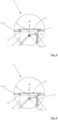
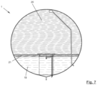
Figur 1 gezeigte Ausführungsbeispiel eines erfindungsgemäßen Treibstofftanks 1 für Treibstoffe weist eine Tankwand 2 mit einem Mannloch 3 auf, wobei in einer Mannlochabdeckung 4 ein Tankauslass 5 und durch die Tankwand 2 eine Leerraumgaszufuhr 6 angeordnet sind. Der Treibstofftank 1 ist beispielsweise ein Treibstofftank einer Trägerrakete. - Der Tank 1 hat hier einen kreisförmigen Querschnitt (siehe Schnitt A-A in
Figur 2 ). Der Innenraum des Treibstofftanks 1 ist durch einen Abteiltrenner 7 mit einem Abteiltor 8 in ein unteres Abteil 9 und ein oberes Abteil 10 unterteilt. - Der Abteiltrenner 7 weist einen äußeren, mit der Tankwand 2 verbundenen Ring 11 und einem inneren Ring 12 auf, welcher über eine Halterung 13 mit der unteren Tankabdeckung verbunden ist. Der äußere Ring 11 und der innere Ring 12 sind mittels einer Auflageträgerstruktur 14 miteinanderverbunden.
- Der äußere Ring 11 hat einen zur Tankinnenwandung im Anbindungsbereich korrespondierende Außenkontur. Der innere Ring 12 ist um ein Vielfaches kleiner als der äußere Ring 11 und konzentrisch zum äußeren Ring 11 angeordnet.
- Die Auflageträgerstruktur 14 umfasst längliche Profile, die sich sternförmig zwischen den Ringen 11, 12 erstrecken und fest mit diesen verbunden sind. Die Profile teilen einen Ringbereich zwischen den Ringen 11, 12 in eine Vielzahl von gleich großen Segmenten.
- Die Auflageträgerstruktur 14 trägt einen Plattenverbund 15 (z.B. CFRP-GFRP-Verbund), der eine Vielzahl von einzelnen Platten aufweist, Jede Platte ist fluiddicht und hat eine einem Segment korrespondierende Außenkontur bzw. Fläche. Die Platten bedecken bzw. verschließen die Segmente fluiddicht und sind mit der Auflageträgerstruktur 14, dem äußeren Ring 11 und dem inneren Ring 12 mechanisch fixiert bzw. verklebt ist.
- Wie in den
Figuren 3 und 4 skizziert, befindet sich im inneren Ring 12 das Abteiltor 8, welches eine Hebescheibe 16 mit einem Diffusorring 17 aufweist. Der Diffusorring 17 ist an der Hebescheibe 16 angebunden und hat einen Außendurchmesser, der einem Innendurchmesser des Abteiltors 8 entspricht. Der Diffusorring 17 führt somit jede Bewegung der Hebescheibe 17 mit aus bzw. wird von der Hebescheibe 17 mitgeführt. - In
Figur 3 ist das Abteiltor 8 nominal geöffnet und lässt den Flüssigtreibstoff oder das Leerraumgas über den Diffusorring 17 vom oberen Abteil 10 zum unteren Abteil 9. Der Diffusorring 17 bewirkt dabei eine optimale Verteilung des in das untere Abteil 9 eindringende Leerraumgases und ermöglicht damit für einen geeigneten Druckausgleich zwischen den beiden Abteils 9, 10. - Beim Durchströmen des Diffusorrings 17 wird ein Druckverlust erzeugt, welcher sich aber bei der ersten Antriebsphase nicht negativ auf die Triebwerksleistung auswirkt, da die Stratifikation noch nicht soweit fortgeschritten ist und bis zur Pumpenkavitation der Flüssigtreibstoff noch stark unterkühlt ist.
- In
Figur 4 ist die Hebescheibe 16 auf fluiddicht auf der Auflageträgerstruktur 14, insbesondere auf dem Plattenverbund 15, abgesenkt und das Abteilrohr 8 somit verschlossen. Das Anheben und Absenken der Hebescheibe 16 erfolgt über eine mit der Hebescheibe 16 verbundenen Stößelstange 22, der tankauslassseitig mittig an der Hebescheibe 16 angreift und mit einer Zylinderkolbeneinheit 23 in Wirkverbindung steht (nicht beziffert). Die Zylinderkolbeneinheit 23 kann weist in einem Federraum eine Druckfeder 24 auf, mittels der die Hebescheibe 16 in Ihrer Öffnungsstellung (Figur 3 ) gehalten wird. Zum Überführen der Hebescheibe 16 in ihre Schließstellung (Figur 4 ) wird über ein Leitung 25 ein Fluiddruck in einen Zylinderraum 26 zu führen, derart, dass ein Kolben mit einer gegen die Federkraft wirkenden und diese überwindenden Druckkraft beaufschlagt wird, so dass die Druckfeder 24 gestaucht wird und hierdurch die Stößelstange 22 und somit die Hebescheibe 16 mitgenommen wird. Die Ansteuerung von erforderlichen Ventilen der Zylinderkolbeneinheit 23 kann elektropneumatisch, elektrohydraulisch oder mechanisch erfolgen. Ein beispielhaftes, über die Leitung 25 in den Zylinderraum 26 geführtes Gas zum Erzeugen der Druckkraft zum Schließen des Abteiltors 8 ist Helium. - Denkbar ist es, dass der Hebemechanismus der Hebescheibe 16 ersatzweise auch mit einem Spiralantrieb als rotierende absenkende Scheibe ausgeführt wird.
- Im Folgen wird anhand der
Figuren 5 bis 7 ein bevorzugtes erfindungsgemäßes Verfahren zum Betrieb am Beispiel des Fluges einer Trägerrakete mit dem Treibstofftank 1 von der Erde in den Orbit erläutert werden. - Vor der ersten Antriebsphase (
Fig. 5 ) wird, bei geöffnetem Abteiltor 8, das tankauslassseitige bzw. untere Abteil 9 und das leergaszufuhrseitige bzw. obere Abteil 10 vollständig mit Flüssigtreibstoff 19 gefüllt. Dazu wird über den Tankauslass 5 Flüssigtreibstoff 19 dem unteren Abteil 8 zugeführt und über die Leerraumgaszufuhr 6 das Leerraumgas aus dem oberen Abteil 10 abgeführt. - In der ersten Antriebsphase, dem Flug der Trägerrakete von der Erde bis in den Orbit, ist das Abteiltor 8 weiterhin geöffnet. Aus dem unteren Abteil 9 wird über den Tankauslass 5 Flüssigtreibstoff 19 entnommen und über die Leerraumgaszufuhr 6 das Leerraumgas 20 aus dem oberen Abteil 10 dem unteren Abteil 9 zugeführt. Dabei fließt der Flüssigtreibstoff 19 aus dem oberen Abteil 10 durch den Diffusorring 17 in das untere Abteil 11.
- Nach der ersten Antriebsphase (
Fig. 6 ), mit dem Erreichen der Trägerrakete des Orbits, ist das obere Abteil 10 vollständig mit Leerraumgas 20 befüllt. Im unteren Abteil 9 befindet sich Flüssigtreibstoff 19 mit einer kleinen Menge an aus dem oberen Abteil 10 bei der Treibstoffentnahme nachgeströmten Leerraumgas 21. Das Leerraumgas 21 ist dabei auf das Temperaturniveau des Flüssigkeitstreibstoffes 19 abgekühlt. Das Abteiltor 8 ist noch geöffnet. - In den nächsten Antriebsphasen (
Fig. 7 ) wird das Abteiltor 8 geschlossen, so dass der Flüssigtreibstoff 19 nicht in das obere Abteil 10 gelangen kann. Dazu wird die Hebescheibe 16 mit Diffusorring 17 aktiviert und schließt dann die beiden Abteile 9, 10 voneinander ab. Dabei sind das hochenergetische Leerraumgas 20 im oberen Abteil 10 und der kalte Flüssigtreibstoff 19 im unteren Abteil 9. Aufgrund der gewählten Materialien des Plattenverbundes 15 findet nur ein geringer Wärmeaustausch mittels Konvektion und Strahlung vom oberen Abteil 10 zum unteren Abteil 9 statt. - Um zu verhindern, dass bei geschlossenem Abteiltor 8 und gleichzeitiger Flüssigtreibstoffentnahme aus dem unteren Abteil 9, ein zu großer Differenzdruck zwischen dem unteren Abteil 9 und dem oberen Abteil 10 entsteht, wird dem unteren Abteil 9 über eine eigene Leerraumgaszufuhr 18 ein Inertgas oder ein Gas aus anderen Quellen (sekundäre Hilfseinheit) zugeführt.
- Ist diese eigene Leerraumgaszufuhr 18 nicht vorhanden, kann der Druckausgleich zwischen den unteren Abteil 9 und dem oberen Abteil 10 durch das Öffnen des Abteiltors 8 erfolgen.
- Um im unteren Abteil 9 die Evaporation des Flüssigtreibstoffs 19 durch das aus dem oberen Abteil 10 nachgeströmte heiße Leerraumgas 20 zu verringern, ist es denkbar, die Wärmeübertragungsfläche zwischen Flüssigtreibstoff 19 und Leerraumgas 21 zu verringern.
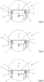
- Dies kann beispielsweise dadurch erreicht werden, dass die Halterung 13, wie in den Figuren
Fig. 8 bis 10 gezeigt, als eine hohlzylinderförmige Halterung 27 ausgeführt ist, wobei die Hebescheibe 16 die Deckfläche der hohlzylinderförmigen Halterung 27 und das Mannloch 3 mit der Mannlochabdeckung 4 die Grundfläche der hohlzylinderförmigen Halterung 27 ausbilden. Außerdem weist die hohlzylinderförmige Halterung 27 auf ihrer Mantelfläche einen oberen Diffusor 28 und eine in denFiguren 11 bis 13 dargestellten unteren Durchlassöffnung 32 auf, wobei die untere Durchlassöffnung 32 im unteren Abteil 9 einen ständigen Druckausgleich zwischen dem Innenraum der hohlzylinderförmigen Halterung 27 und dem die Mantelfläche der hohlzylinderförmigen Halterung 27 umgebenen Außenraum erreicht. - Auch ist an der Hebescheibe 16 neben dem (ersten) Diffusorring 17 ein zweiter Diffusorring 29 mit einem Schieberring 30 angeordnet, wobei ihre Dimensionierung derart ist, dass in einer zusätzlichen mittleren Stellung des Abteiltors 8 der innere Ring 12 den zweiten Diffusorring 29 verschließt und der Schieberring 30 den oberen Diffusor 28 verschließt. Der zweite Diffusorring 29 ist somit zwischen dem ersten Diffusorring 17 und dem Schiebering 30 angeordnet.
- In den
Fig. 8 bis 10 sind die drei Stellung des Abteiltors 8 zusammengefasst. InFig. 8 sind die beiden Diffusorringe 17, 29 und der obere Diffusor 28 geöffnet. InFig. 9 ist nur der Diffusorring 17 geöffnet. Der Diffusorring 29 und der obere Diffusor 28 hingegen sind geschlossen, so dass der Druckausgleich zwischen dem Innenraum der hohlzylinderförmigen Halterung 27 und dem die Mantelfläche der hohlzylinderförmigen Halterung 27 umgebenen Außenraum ausschließlich über die untere Durchlassöffnung erreicht wird. InFig. 10 sind die Diffusorringe 17, 29 und der obere Diffusor 28 geschlossen. - Das alternative in den
Figuren 8, 9 und 10 gezeigte Ausführungsbeispiel wird nun anhand der Figurrn11, 12 und 13 mit anderen Worten erläutert, Die Hebeeinrichtung ist mit einem doppelten Diffusor 17, 29 versehen und die Stützhalterung 27 mit einer oberen Durchlassöffnung 28 (oberen Diffusor 28) und einer unteren Durchlassöffnung 32. Das untere Abteil 9 ist funktional in zwei Unterabteile unterteilt, und zwar in bezogen auf die Stützhalterung 27 inneres Bedrückungsunterabteil 9.1 (Innenraum) und in ein äußeres Lagerunterabteil 9.2 (Außenraum). - In
Figur 11 ist nun gezeigt, wie die Hebeeinrichtung 27 nominal ausgefahren und die Treibstoffflüssigkeit vom oberen Abteil 10 über die doppelte Diffusorreihe 17, 29 der Hebeeinrichtung 27 zum Bedrückungsunterabteil 9.1 und durch den oberen Diffusor 28 auch ins Lagerunterteil 9.2 gelangt. Nominal unten sind das Bedrückungsunterabteil 9.1 und das Lagerunterteil 9.2 zum Tankauslass immer offen verbunden. Die Treibstoffflüssigkeit kann nominal durch alle Abteile 9, 9.1.9.2 fließen. Der inFigur 8 gezeigte Zustand trifft in der ersten Antriebsphase, der sogenannten Boost Phase 1 ein. - In
Figur 12 ist die erste Absenkung der Hebeeinrichtung gezeigt, um das Bedrückungsunterteil 9.1 und das Lagerabteil 9.2 oben zu entkoppeln. Dabei wird nur noch Fluid vom oberen Abteil 10 in das Bedrückungsunterteil zu 9.1 direkt geleitet. Diese Phase ist z.B. die Wiederbedrückung-Phase, bei der das warme Bedrückungsgas vom oberen Abteil 10 nur in das untere Bedrückungsabteil 9.1 geleitet wird. Hierdurch ist die freie Oberfläche für die Evaporation wesentlich kleiner als bei Öffnung des Bedrückungsabteils 9.1 zum Lagerabteil 9.2 im oberen Bereich. Wenn das untere Abteil 9 zum Beispiel eine eigene Leerraumgaszufuhr 18 (sekundär Bedrückungssystem) aufweist, wird die inFigur 9 gezeigte Position (bevorzugt) nicht eingestellt. - In
Figur 13 ist gezeigt, wie die Hebeeinrichtung komplett abgesenkt ist. Sämtliche Diffusoröffnungen 17, 28, 29, sind geschlossen. Das obere Abteil 10 und das untere Abteil 9 sind fluidtechnisch getrennt voneinander. Lediglich das Bedrückungsabteil 9.1 und das Lagerabteil 9.2 sind über die untere Durchlassöffnung 32 fluidtechnisch miteinander verbunden bzw. nominal zueinander geöffnet. - Denkbar ist es, dass das Abteitores 8 vor allem bei Manövern mit Schwapp-Bewegungen und beim Aussetzten der Nutzlast, wo negative Beschleunigungen entstehen, geschlossen wird. Damit wird verhindert, dass kalter Flüssigtreibstoff in das obere Abteil 10 gelangt und das warme Leerraumgas nur geringen Kontakt mit dem kalten Flüssigtreibstoff hat.
- Denkbar ist es auch, dass das obere Abteil 10 auch ein Gaspuffer für ein Gas-Lageregelungssystem ist.
- Offenbart sind ein Treibstofftank für einen Flüssigtreibstoff, mit einem Tankauslass (5) und einer Leerraumgaszufuhr (6) dadurch, dass der Innenraum des Treibstofftanks (1) durch einen Abteiltrenner (7) mit einem Abteiltor (8) in zwei Abteile (9, 10) unterteilt ist, die über das Abteiltor (8) fluidtechnisch miteinander verbindbar oder voneinander trennbar sind, wobei der Tankauslass (5) dem einen Abteil (9) und die Leergaszufuhr (6) dem anderen Abteil (10) zugeordnet sind ist und ein Verfahren zum Betreiben eines derartigen Treibstofftanks (1).
-
- 1
- Treibstofftank
- 2
- Tankwand
- 3
- Mannloch
- 4
- Mannlochabdeckung
- 5
- Tankauslass
- 6
- Leerraumgaszufuhr
- 7
- Abteiltrenner
- 8
- Abteiltor 8
- 9
- unteres Abteil
- 9.1
- Bedrückungsunterabteil / Innenraum
- 9.2
- Lagerunterabteil / Außenraum
- 10
- oberes Abteil
- 11
- äußerer Ring
- 12
- innerer Ring
- 13
- Halterung
- 14
- Auflageträgerstruktur
- 15
- Plattenverbund
- 16
- Hebescheibe
- 17
- Diffusorring
- 18
- eigene Leerraumgaszufuhr
- 19
- Flüssigbrennstoff
- 20
- Leerraumgas
- 21
- Inertgas
- 22
- Stößelstange
- 23
- Zylinderkolbeneinheit
- 24
- Druckfeder
- 25
- Leitung
- 26
- Zylinderraum
- 27
- hohlzylinderförmige Halterung / Stützhalterung
- 28
- oberer Diffusor
- 29
- zweiter Diffusorring
- 30
- Schieberring
- 32
- untere Diffusoröffnung
Claims (10)
- Treibstofftank für Flüssigtreibstoff, mit einem Tankauslass (5) und einer Leerraumgaszufuhr (6), dadurch gekennzeichnet, dass der Innenraum des Treibstofftanks (1) durch einen Abteiltrenner (7) mit einem Abteiltor (8) in zwei Abteile (9, 10) unterteilt ist, die über das Abteiltor (8) fluidtechnisch miteinander verbindbar oder voneinander trennbar sind, wobei der Tankauslass (5) dem einen Abteil (9) und die Leergaszufuhr (6) dem anderen Abteil (10) zugeordnet sind ist.
- Treibstofftank nach Anspruch 1, wobei der Abteiltrenner (7) einen äußeren, mit der Tankwand (2) verbundenen Ring (11) und einem das Abteiltor (8) tragenden inneren Ring (12) aufweist, wobei der äußere Ring (11) und der innere Ring (12) mittels einer Auflageträgerstruktur (14) miteinander verbunden sind und diese Auflagestruktur (14) einen Plattenverbund (15) trägt.
- Treibstofftank nach Anspruch 2, wobei der Plattenverbund (15) zumindest teilweise aus dem gleichen Material wie die Auflageträgerstruktur (CFRP) besteht.
- Treibstofftank nach Anspruch 2 oder 3, wobei der innere Ring (12) mit einer ein Mannloch (3) umgebenden Tankinnenstruktur (13) verbunden ist.
- Treibstofftank nach einem der vorhergehenden Ansprüche, wobei das Abteiltor (8) eine Hebescheibe (16) mit einem an der Hebescheibe (16) befestigten Diffusorring (17, 29) aufweist, wobei :- bei geöffnetem Abteiltor (8) das untere Abteil (9) und das obere Abteil (10) über den Diffusorring (17, 29) miteinander verbunden und- bei geschlossenem Abteiltor (8) das untere Abteil (9) und das obere Abteil (10) durch die Hebescheibe (16) voneinander getrennt sind.
- Treibstofftank nach einem der Patentansprüche 2 bis 5, wobei die Halterung (27) hohlzylinderförmig ausgebildet ist und auf ihrer Mantelfläche einen oberen Diffusor (28) aufweist, und wobei ein zweiter Diffusorring (29) und ein Schiebering (30) vorgesehen sind, derart, dass in einer mittleren Stellung des Abteiltors (8) der innere Ring (12) den zweiten Diffusorring (29) verschließt und der Schieberring (30) den oberen Diffusor (28) verschließt.
- Treibstofftank nach Anspruch 5 oder 6, wobei der flexible Abteiltrenner (7) derart im Innenraum des Treibstofftanks (1) angeordnet ist, dass:- das obere Abteil (10) die für die ersten Antriebsphase benötigten Menge an Flüssigtreibstoff aufnimmt und- sich der in den nächsten Antriebsphasen benötigte Flüssigtreibstoff im unteren Abteil (9) befindet.
- Treibstofftank nach Anspruch 6 oder 7, wobei im unteren Abteil (9) eine weitere Leerraumgaszufuhr (18) angeordnet ist, wobei die Leerraumgaszufuhren (6, 18) in Form eines Diffusors ausgeführt sind.
- Verfahren zum Betrieb eines Treibstofftank nach einem der vorhergehenden Ansprüche, wobei das Abteitor (8) bei Manövern mit Schwapp-Bewegungen und beim Aussetzten der Nutzlast geschlossen ist.
- Verfahren nach Anspruch 8 oder 9, wobei bei geschlossenem Abteitor (8) und gleichzeitiger Flüssigtreibstoffentnahme aus dem unteren Abteil (9) über die eigene Leerraumgaszufuhr (18) ein Inertgas oder anderen Quellen in das untere Abteil (9) zugeführt wird.
Applications Claiming Priority (1)
| Application Number | Priority Date | Filing Date | Title |
|---|---|---|---|
| DE102023112617.2A DE102023112617B4 (de) | 2023-05-12 | 2023-05-12 | Treibstofftank für Flüssigtreibstoff und Verfahren zum Betrieb dieses Treibstofftanks |
Publications (1)
| Publication Number | Publication Date |
|---|---|
| EP4462009A1 true EP4462009A1 (de) | 2024-11-13 |
Family
ID=90789264
Family Applications (1)
| Application Number | Title | Priority Date | Filing Date |
|---|---|---|---|
| EP24170769.4A Pending EP4462009A1 (de) | 2023-05-12 | 2024-04-17 | Treibstofftank für flüssigtreibstoff und verfahren zum betrieb dieses treibstofftanks |
Country Status (2)
| Country | Link |
|---|---|
| EP (1) | EP4462009A1 (de) |
| DE (1) | DE102023112617B4 (de) |
Citations (3)
| Publication number | Priority date | Publication date | Assignee | Title |
|---|---|---|---|---|
| US20210403180A1 (en) * | 2017-06-22 | 2021-12-30 | Arianegroup Sas | Tank for a spacecraft engine |
| CN115199437B (zh) * | 2022-09-08 | 2022-12-27 | 北京凌空天行科技有限责任公司 | 一种液位可控的蓄留阱结构 |
| US20230027991A1 (en) * | 2019-12-18 | 2023-01-26 | Posco | Lng storage tank and ship having thereof |
Family Cites Families (3)
| Publication number | Priority date | Publication date | Assignee | Title |
|---|---|---|---|---|
| DE3146262A1 (de) | 1981-11-21 | 1983-05-26 | Erno-Raumfahrttechnik Gmbh, 2800 Bremen | "treibstofftank" |
| DE10040755C2 (de) | 2000-08-19 | 2002-06-27 | Astrium Gmbh | Treibstofftank |
| DE102005062092B3 (de) | 2005-12-22 | 2007-03-29 | Eads Space Transportation Gmbh | Treibstofftank |
-
2023
- 2023-05-12 DE DE102023112617.2A patent/DE102023112617B4/de active Active
-
2024
- 2024-04-17 EP EP24170769.4A patent/EP4462009A1/de active Pending
Patent Citations (3)
| Publication number | Priority date | Publication date | Assignee | Title |
|---|---|---|---|---|
| US20210403180A1 (en) * | 2017-06-22 | 2021-12-30 | Arianegroup Sas | Tank for a spacecraft engine |
| US20230027991A1 (en) * | 2019-12-18 | 2023-01-26 | Posco | Lng storage tank and ship having thereof |
| CN115199437B (zh) * | 2022-09-08 | 2022-12-27 | 北京凌空天行科技有限责任公司 | 一种液位可控的蓄留阱结构 |
Also Published As
| Publication number | Publication date |
|---|---|
| DE102023112617A1 (de) | 2024-11-14 |
| DE102023112617B4 (de) | 2024-12-05 |
Similar Documents
| Publication | Publication Date | Title |
|---|---|---|
| DE19916385C2 (de) | Fahrzeug mit Druckgasbehälter als Fahrzeugtank | |
| DE102011119921B3 (de) | Raketenstufe mit Flüssigantriebssystem | |
| DE112006002328T5 (de) | Wasserstoffspeichervorrichtung | |
| EP2130768A1 (de) | Tank zur Lagerung kryogener Flüssigkeiten und lagerfähiger Treibstoffe | |
| EP1953445A1 (de) | Tank zur Lagerung kryogener Flüssigkeiten und lagerfähiger Treibstoffe | |
| DE102020214000A1 (de) | Zentrifuge mit elastokalorischer kühlung und verfahren zur kühlung einer zentrifuge | |
| DE2558354B2 (de) | Raumfahrzeug | |
| DE2215375A1 (de) | Trommel für Rotationsfilter | |
| DE102008050404A1 (de) | Behälter zum Aufnehmen und Speichern von Flüssigkeiten und viskosen Stoffen, insbesondere von kryogenen Fluiden, und Verfahren zu dessen Herstellung sowie zur Verwendung dessen | |
| DE102011087889B4 (de) | Unterseeboot | |
| DE102007039753A1 (de) | Kältemittelakkumulator für Kraftfahrzeugklimaanlagen | |
| DE102023112617B4 (de) | Treibstofftank für Flüssigtreibstoff und Verfahren zum Betrieb dieses Treibstofftanks | |
| DE19849767C1 (de) | Speicherbehälter für verflüssigte Gase | |
| DE69005765T2 (de) | Druckgasgefäss mit kontrollierter Gasabgabe. | |
| DE8121663U1 (de) | Elektrohydraulischer stellantrieb fuer ventile | |
| DE102007046905A1 (de) | Schichtspeicher | |
| DE1274255B (de) | Vorrichtung zum Regeln der Moderation in einem Kernreaktor | |
| DE102019004754B4 (de) | Scharnier, Staufachanordnung und Umrüstverfahren | |
| EP3210890A1 (de) | Kühlung von treibstoff für ein triebwerk | |
| DE10351713A1 (de) | Träger für den Transport einer Nutzlast und Verfahren zum Ändern der Umlaufbahn eines Trägers | |
| DE2333824C3 (de) | Kernkraftanlage | |
| EP4267388A1 (de) | Tanksystem zur lagerung kühler medien | |
| DE102011122352B4 (de) | Tank zur Separation von Flüssigkeiten im Orbit | |
| DE8121690U1 (de) | Elektrohydralischer stellantrieb fuer ventile | |
| DE102018133182A1 (de) | Druckbehältersystem, Raketentank und Luftfahrzeug, Raumfahrzeug und kombiniertes Luft-/Raumfahrzeug |
Legal Events
| Date | Code | Title | Description |
|---|---|---|---|
| PUAI | Public reference made under article 153(3) epc to a published international application that has entered the european phase |
Free format text: ORIGINAL CODE: 0009012 |
|
| STAA | Information on the status of an ep patent application or granted ep patent |
Free format text: STATUS: THE APPLICATION HAS BEEN PUBLISHED |
|
| AK | Designated contracting states |
Kind code of ref document: A1 Designated state(s): AL AT BE BG CH CY CZ DE DK EE ES FI FR GB GR HR HU IE IS IT LI LT LU LV MC ME MK MT NL NO PL PT RO RS SE SI SK SM TR |
|
| STAA | Information on the status of an ep patent application or granted ep patent |
Free format text: STATUS: REQUEST FOR EXAMINATION WAS MADE |
|
| 17P | Request for examination filed |
Effective date: 20250425 |
|
| GRAP | Despatch of communication of intention to grant a patent |
Free format text: ORIGINAL CODE: EPIDOSNIGR1 |
|
| STAA | Information on the status of an ep patent application or granted ep patent |
Free format text: STATUS: GRANT OF PATENT IS INTENDED |
|
| INTG | Intention to grant announced |
Effective date: 20260323 |