EP4461981A1 - Dreireihiges wälzlager, vorzugsweise zur verwendung in einer windkraftanlage - Google Patents
Dreireihiges wälzlager, vorzugsweise zur verwendung in einer windkraftanlage Download PDFInfo
- Publication number
- EP4461981A1 EP4461981A1 EP23172127.5A EP23172127A EP4461981A1 EP 4461981 A1 EP4461981 A1 EP 4461981A1 EP 23172127 A EP23172127 A EP 23172127A EP 4461981 A1 EP4461981 A1 EP 4461981A1
- Authority
- EP
- European Patent Office
- Prior art keywords
- inner ring
- bearing
- rotor blade
- side inner
- row roller
- Prior art date
- Legal status (The legal status is an assumption and is not a legal conclusion. Google has not performed a legal analysis and makes no representation as to the accuracy of the status listed.)
- Withdrawn
Links
Images

Classifications
-
- F—MECHANICAL ENGINEERING; LIGHTING; HEATING; WEAPONS; BLASTING
- F16—ENGINEERING ELEMENTS AND UNITS; GENERAL MEASURES FOR PRODUCING AND MAINTAINING EFFECTIVE FUNCTIONING OF MACHINES OR INSTALLATIONS; THERMAL INSULATION IN GENERAL
- F16C—SHAFTS; FLEXIBLE SHAFTS; ELEMENTS OR CRANKSHAFT MECHANISMS; ROTARY BODIES OTHER THAN GEARING ELEMENTS; BEARINGS
- F16C19/00—Bearings with rolling contact, for exclusively rotary movement
- F16C19/22—Bearings with rolling contact, for exclusively rotary movement with bearing rollers essentially of the same size in one or more circular rows, e.g. needle bearings
- F16C19/34—Bearings with rolling contact, for exclusively rotary movement with bearing rollers essentially of the same size in one or more circular rows, e.g. needle bearings for both radial and axial load
- F16C19/38—Bearings with rolling contact, for exclusively rotary movement with bearing rollers essentially of the same size in one or more circular rows, e.g. needle bearings for both radial and axial load with two or more rows of rollers
- F16C19/381—Bearings with rolling contact, for exclusively rotary movement with bearing rollers essentially of the same size in one or more circular rows, e.g. needle bearings for both radial and axial load with two or more rows of rollers with at least one row for radial load in combination with at least one row for axial load
-
- F—MECHANICAL ENGINEERING; LIGHTING; HEATING; WEAPONS; BLASTING
- F16—ENGINEERING ELEMENTS AND UNITS; GENERAL MEASURES FOR PRODUCING AND MAINTAINING EFFECTIVE FUNCTIONING OF MACHINES OR INSTALLATIONS; THERMAL INSULATION IN GENERAL
- F16C—SHAFTS; FLEXIBLE SHAFTS; ELEMENTS OR CRANKSHAFT MECHANISMS; ROTARY BODIES OTHER THAN GEARING ELEMENTS; BEARINGS
- F16C33/00—Parts of bearings; Special methods for making bearings or parts thereof
- F16C33/30—Parts of ball or roller bearings
- F16C33/58—Raceways; Race rings
- F16C33/581—Raceways; Race rings integral with other parts, e.g. with housings or machine elements such as shafts or gear wheels
-
- F—MECHANICAL ENGINEERING; LIGHTING; HEATING; WEAPONS; BLASTING
- F16—ENGINEERING ELEMENTS AND UNITS; GENERAL MEASURES FOR PRODUCING AND MAINTAINING EFFECTIVE FUNCTIONING OF MACHINES OR INSTALLATIONS; THERMAL INSULATION IN GENERAL
- F16C—SHAFTS; FLEXIBLE SHAFTS; ELEMENTS OR CRANKSHAFT MECHANISMS; ROTARY BODIES OTHER THAN GEARING ELEMENTS; BEARINGS
- F16C33/00—Parts of bearings; Special methods for making bearings or parts thereof
- F16C33/30—Parts of ball or roller bearings
- F16C33/58—Raceways; Race rings
- F16C33/583—Details of specific parts of races
- F16C33/586—Details of specific parts of races outside the space between the races, e.g. end faces or bore of inner ring
-
- F—MECHANICAL ENGINEERING; LIGHTING; HEATING; WEAPONS; BLASTING
- F16—ENGINEERING ELEMENTS AND UNITS; GENERAL MEASURES FOR PRODUCING AND MAINTAINING EFFECTIVE FUNCTIONING OF MACHINES OR INSTALLATIONS; THERMAL INSULATION IN GENERAL
- F16C—SHAFTS; FLEXIBLE SHAFTS; ELEMENTS OR CRANKSHAFT MECHANISMS; ROTARY BODIES OTHER THAN GEARING ELEMENTS; BEARINGS
- F16C33/00—Parts of bearings; Special methods for making bearings or parts thereof
- F16C33/30—Parts of ball or roller bearings
- F16C33/58—Raceways; Race rings
- F16C33/60—Raceways; Race rings divided or split, e.g. comprising two juxtaposed rings
-
- F—MECHANICAL ENGINEERING; LIGHTING; HEATING; WEAPONS; BLASTING
- F16—ENGINEERING ELEMENTS AND UNITS; GENERAL MEASURES FOR PRODUCING AND MAINTAINING EFFECTIVE FUNCTIONING OF MACHINES OR INSTALLATIONS; THERMAL INSULATION IN GENERAL
- F16C—SHAFTS; FLEXIBLE SHAFTS; ELEMENTS OR CRANKSHAFT MECHANISMS; ROTARY BODIES OTHER THAN GEARING ELEMENTS; BEARINGS
- F16C19/00—Bearings with rolling contact, for exclusively rotary movement
- F16C19/54—Systems consisting of a plurality of bearings with rolling friction
- F16C19/56—Systems consisting of a plurality of bearings with rolling friction in which the rolling bodies of one bearing differ in diameter from those of another
-
- F—MECHANICAL ENGINEERING; LIGHTING; HEATING; WEAPONS; BLASTING
- F16—ENGINEERING ELEMENTS AND UNITS; GENERAL MEASURES FOR PRODUCING AND MAINTAINING EFFECTIVE FUNCTIONING OF MACHINES OR INSTALLATIONS; THERMAL INSULATION IN GENERAL
- F16C—SHAFTS; FLEXIBLE SHAFTS; ELEMENTS OR CRANKSHAFT MECHANISMS; ROTARY BODIES OTHER THAN GEARING ELEMENTS; BEARINGS
- F16C2300/00—Application independent of particular apparatuses
- F16C2300/10—Application independent of particular apparatuses related to size
- F16C2300/14—Large applications, e.g. bearings having an inner diameter exceeding 500 mm
-
- F—MECHANICAL ENGINEERING; LIGHTING; HEATING; WEAPONS; BLASTING
- F16—ENGINEERING ELEMENTS AND UNITS; GENERAL MEASURES FOR PRODUCING AND MAINTAINING EFFECTIVE FUNCTIONING OF MACHINES OR INSTALLATIONS; THERMAL INSULATION IN GENERAL
- F16C—SHAFTS; FLEXIBLE SHAFTS; ELEMENTS OR CRANKSHAFT MECHANISMS; ROTARY BODIES OTHER THAN GEARING ELEMENTS; BEARINGS
- F16C2360/00—Engines or pumps
- F16C2360/31—Wind motors
-
- F—MECHANICAL ENGINEERING; LIGHTING; HEATING; WEAPONS; BLASTING
- F16—ENGINEERING ELEMENTS AND UNITS; GENERAL MEASURES FOR PRODUCING AND MAINTAINING EFFECTIVE FUNCTIONING OF MACHINES OR INSTALLATIONS; THERMAL INSULATION IN GENERAL
- F16C—SHAFTS; FLEXIBLE SHAFTS; ELEMENTS OR CRANKSHAFT MECHANISMS; ROTARY BODIES OTHER THAN GEARING ELEMENTS; BEARINGS
- F16C33/00—Parts of bearings; Special methods for making bearings or parts thereof
- F16C33/30—Parts of ball or roller bearings
- F16C33/66—Special parts or details in view of lubrication
- F16C33/6603—Special parts or details in view of lubrication with grease as lubricant
- F16C33/6622—Details of supply and/or removal of the grease, e.g. purging grease
-
- F—MECHANICAL ENGINEERING; LIGHTING; HEATING; WEAPONS; BLASTING
- F16—ENGINEERING ELEMENTS AND UNITS; GENERAL MEASURES FOR PRODUCING AND MAINTAINING EFFECTIVE FUNCTIONING OF MACHINES OR INSTALLATIONS; THERMAL INSULATION IN GENERAL
- F16C—SHAFTS; FLEXIBLE SHAFTS; ELEMENTS OR CRANKSHAFT MECHANISMS; ROTARY BODIES OTHER THAN GEARING ELEMENTS; BEARINGS
- F16C33/00—Parts of bearings; Special methods for making bearings or parts thereof
- F16C33/30—Parts of ball or roller bearings
- F16C33/66—Special parts or details in view of lubrication
- F16C33/6603—Special parts or details in view of lubrication with grease as lubricant
- F16C33/6629—Details of distribution or circulation inside the bearing, e.g. grooves on the cage or passages in the rolling elements
-
- Y—GENERAL TAGGING OF NEW TECHNOLOGICAL DEVELOPMENTS; GENERAL TAGGING OF CROSS-SECTIONAL TECHNOLOGIES SPANNING OVER SEVERAL SECTIONS OF THE IPC; TECHNICAL SUBJECTS COVERED BY FORMER USPC CROSS-REFERENCE ART COLLECTIONS [XRACs] AND DIGESTS
- Y02—TECHNOLOGIES OR APPLICATIONS FOR MITIGATION OR ADAPTATION AGAINST CLIMATE CHANGE
- Y02E—REDUCTION OF GREENHOUSE GAS [GHG] EMISSIONS, RELATED TO ENERGY GENERATION, TRANSMISSION OR DISTRIBUTION
- Y02E10/00—Energy generation through renewable energy sources
- Y02E10/70—Wind energy
- Y02E10/72—Wind turbines with rotation axis in wind direction
Definitions
- the present invention relates to a three-row roller bearing with an outer ring and a two-piece inner ring, the outer ring and the inner ring being rotatable relative to each other about an axis of rotation.
- pitch systems Such bearings are widely used in wind power plants in so-called pitch systems.
- a pitch system of a wind turbine controls the power of the turbine via the position of the rotor blades in relation to the wind by enabling rotation of the rotor blades about a pitch axis.
- the efficiency of the turbine is thus optimized based on the prevailing wind conditions.
- the pitch system can be seen as part of the brake system that helps prevent failures in the bearing or the entire power plant. Therefore, three-row roller bearings play a vital role in realizing the functionalities of the pitch system and maintaining safety.
- the use of three-row roller bearings implies also risks, since the bearing comprises three separate rings - one outer and two inner rings - that are prone to sliding relative to each other, especially in case of a pitch system with an internal gear where forces are being transmitted or due to forces induced by radial rollers.
- Such bearing designs can result in displacements and deformities due to forces transmitted through meshing gears and therefore create lubrication problems due to a loss of lubricant.
- sliding of the rings can damage the raceway system (crushed roller cages), the bolted joints and also affect the gear mesh.
- the driving pinion shaft of the pitch system is usually designed as short as possible in order to reduce its flexion under the prevailing loads.
- the bearing gear is usually arranged close to the hub of the wind turbine and consequently rather away from the rotor blades.
- arranging the bearing gear close to the hub necessitates a bearing design that can worsen lubrication problems.
- Lubrication holes are usually formed in a contact area between the two inner rings or at least partially through a contact area. When the inner rings move and deform under load the integrity of lubrication holes is endangered and leakage can be caused.
- the object of the present invention is achieved by a three-row roller bearing, preferably for use in a wind power plant, with an outer ring and a two-piece inner ring, the outer ring and the inner ring being rotatable relative to each other about an axis of rotation,
- the internal bearing gear is driven by a driving pinion, both the bearing gear and the pinion gear being preferably formed as spur gears so as to reduce costs by implementing a geometry that is easier and therefore cheaper to manufacture.
- the two inner rings in combination can be formed as a C shape.
- the opening of the C shape is directed outwards, facing the outer ring.
- the volume in the C shape can receive axial and radial rollers.
- two rows of axial rollers and a row of radial rollers are arranged between the outer ring and the inner ring, the axial rollers and the radial rollers being movable around the axis of rotation, wherein the one row of radial rollers is arranged between the two rows axial rollers.
- the radial rollers can be loaded perpendicularly to the axis of rotation, whereas the axial rollers can be loaded parallel to the axis of rotation.
- the radial rollers are arranged in the middle of the two rows of axial rollers, hereby creating a symmetric arrangement. A symmetric arrangement results in an improved load distribution within the bearing.
- the rotor blade side inner ring and the hub side inner ring physically abut to each other via a contact area.
- the hub side inner ring and the rotor blade side inner ring can each comprise a lateral surface facing and physically in touch with each other.
- the lateral surfaces of the two rings are arranged, preferably, flush with each other.
- the lateral surfaces of the two inner rings have the same size as the contact area. It is also conceivable that the lateral surfaces are greater than the contact area.
- the lateral surface of the hub side inner ring can be larger or smaller than the lateral surface of the rotor blade side inner ring. They can also be equal.
- the contact area can be cylinder-shaped and comprise recesses.
- the recesses can be used for mounting purposes, especially for inserting assembly bolts, tapered and/or threaded pins in order to firmly connect the two inner rings with a rotor blade.
- the radial rollers are preferably arranged in a plane that is arranged at a closer distance to the rotor blade side of the bearing than the contact area.
- the contact area is preferably arranged at a closer distance to the hub side of the bearing than the radial rollers.
- the bearing comprises a lubrication hole that is formed only in the rotor blade side inner ring.
- the bearing comprises a plurality of lubrication holes along a circumferential direction of the three-row roller bearing.
- the number of lubrication holes can be even or odd.
- the lubrication holes can be distributed evenly around the circumference of the bearing or unevenly.
- the one or the many lubrication holes can be formed linearly or comprise a curvature.
- the lubrication holes can comprise a multitude of sections, wherein an individual angle is formed between adjacent sections.
- the lubrication hole extends in the radial and the axial direction of the rotor blade side inner ring.
- the lubrication hole is formed at least partially perpendicular to the contact area.
- a lubrication hole that is formed at least partially perpendicular to the contact area can comprise at least three sections.
- the three sections are formed perpendicularly to each other.
- the lubrication hole has an opening in the rotor blade side inner ring for injecting and/or evacuating a lubricant, the opening facing away from the outer ring.
- the rollers of the three-row roller bearing of a wind power plant can be easily accessed for lubrication purposes from within the hub.
- An opening facing inwards, away from the outer ring, therefore facilitates the access with a lubricant and reduces risks as opposed to an opening that can only be accessed from outside of the wind power plant.
- the contact area and a lateral surface of the bearing gear are arranged parallel to each other, the contact area and the lateral surface being preferably offset.
- a bearing design, wherein the contact area and the lateral surface are offset allows for fine turning of the contact area for a good contact between the two inner rings while the lateral surface of the bearing gear may be machined more economically.
- the hub side inner ring comprises a chamfer facing away from the outer ring.
- the chamfer can be formed advantageously on the hub side of the hub side inner ring and simplify the mounting process due to an enlargement of an internal cross section of the inner ring. Especially when introducing the driving pinion through the internal cross section, the enlargement can prove favorable to avoid contact between the pinion and the bearing and consequently also scratches as well as other mechanical damages that can promote bearing failure in future operation.
- the rotor blade side inner ring is wider than the hub side inner ring.
- the two inner rings can have in a direction perpendicular to the axis of rotation, at least widely, the same dimensions.
- the rotor blade side inner ring can have greater dimensions than the hub side inner ring.
- the rotor blade side inner ring can have a greater volume or require more space than the hub side inner ring.
- a greater volume of the rotor blade side inner ring can be advantageous, since in a greater volume a greater number of lubrication holes can be formed.
- a volume that is sufficiently large can accommodate easilier an internal bearing gear.
- the internal bearing gear can have longer teeth which can be advantageous since the forces transmitted from the driving pinion can be distributed more uniformly.
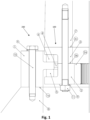
- FIG 1 a three-row roller bearing 100 in a wind power plant 200 according to the state of the art is illustrated schematically in a first section view.
- the wind power plant comprises the bearing 100 and furthermore a rotor blade 7 and a hub 8.
- the bearing 100 enables controlling the rotation of the rotor blade 7 about a pitch axis that is not shown in figure 1 .
- the bearing 100 has an outer ring 1 and a two-piece inner ring 2, 3 that comprises a hub side inner ring 2 and a rotor blade side inner ring 3.
- the outer ring 1 and the inner ring 2, 3 are rotatable relative to each other about an axis of rotation that is not shown in figure 1 .
- the axis of rotation substantially extends parallel to a driving pinion shaft 13a.
- the bearing 100 has a hub side 1a via which the bearing 100, more precisely the outer ring 1, is connected to the hub 8. Moreover, the bearing 100 has a rotor blade side 3c via which the bearing 100, more precisely the inner ring 2, 3, is connected to the rotor blade 7.
- the connections may be realized by bolting, e.g. by means of a first bolt 10, two washers 9, a threaded pin 12 that comprises a male thread at either of its two ends and a nut 11.
- the hub side inner ring 2 comprises an internal bearing gear 2a.
- a driving pinion 13 can drive the internal bearing gear 2a.
- driving the internal bearing gear 2a results in driving of the rotor blade 7, hereby causing the rotation of the rotor blade 7 around the pitch axis.
- Said rotation around the pitch axis can be induced in case wind conditions change, especially in case the vectorial wind velocity (direction and magnitude) changes.
- the three-row roller bearing 100 comprises two rows of axial rollers 5, 6, each row 5 and 6 being rotatable around the axis of rotation.
- the axial rollers 5, 6 can absorb forces parallel to the axis of rotation.
- the bearing 100 comprises a row of radial rollers 4 that is arranged between the outer ring 1 and the inner ring 2, 3.
- the radial rollers 4 are arranged between the two rows axial rollers 5, 6 and absorb forces perpendicular to the axis of rotation.
- a contact area 3b is formed between the rotor blade side inner ring 3 and the hub side inner ring 2 .
- the two inner rings 2, 3 abut physically to each other by means of the contact area 3b.
- the radial rollers 4 are arranged at a closer distance to the hub 8 than the contact area 3b.
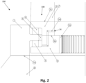
- FIG. 2 illustrates schematically the three-row roller bearing 100 from figure 1 in a second section view.
- lubrication holes 3d can be formed along a circumferential direction of the bearing 100.
- the lubrication hole 3d comprises three sections, adjacent sections being formed perpendicular to each other.
- the lubrication hole 3d comprises an opening 14 via which a lubricant can be pumped to the axial rollers 5, 6 as well as radial rollers 4.
- lubricant that has become used due to operation can be evacuated from the bearing 100 via the opening 14, for instance by means of a suction device that can be connected to the opening 14.
- the middle section of the lubrication hole 3d is formed perpendicularly to the contact area 3b.
- the lubrication hole extends not only through one single inner ring but through both inner rings 2, 3.
- leakage of the lubricant can come about which is one of the major disadvantages in the state of the art bearing designs.
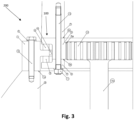
- Figure 3 illustrates schematically a three-row roller bearing 100 in a wind power plant 200 according to the invention in a first section view.
- the rotor blade side inner ring 3 comprises the internal bearing gear 2a.
- the axial extent of the internal bearing gear 2a is preferably at least 30 %, more preferably at least 40 % of the axial extent of the inner ring 2, 3.
- the contact area 3b is formed closer to the hub 8 that the radial rollers 4.
- the rotor blade side inner ring 3 is preferably wider than the hub side inner ring 2.
- the rotor blade side inner ring 3 has a larger volume in order to receive lubrication holes 3d.
- Figure 4 illustrates schematically the three-row roller bearing 100 from figure 3 in a second section view, wherein one lubrication hole 3d can be seen.
- the lubrication hole 3d does not extend through both inner rings 2 and 3, but is formed solely in the rotor blade side inner ring 3. Consequently, none of the sections of the lubrication hole 3d interacts with the contact area 3b.
- Such an optimized bearing design helps avoiding or at least reducing leakage of lubricant.
Landscapes
- Engineering & Computer Science (AREA)
- General Engineering & Computer Science (AREA)
- Mechanical Engineering (AREA)
- Rolling Contact Bearings (AREA)
Priority Applications (4)
| Application Number | Priority Date | Filing Date | Title |
|---|---|---|---|
| EP23172127.5A EP4461981A1 (de) | 2023-05-08 | 2023-05-08 | Dreireihiges wälzlager, vorzugsweise zur verwendung in einer windkraftanlage |
| CN202480031133.7A CN121219503A (zh) | 2023-05-08 | 2024-05-06 | 优选用于风能装置的三列滚子轴承 |
| EP24725099.6A EP4710004A1 (de) | 2023-05-08 | 2024-05-06 | Dreireihiges wälzlager, vorzugsweise zur verwendung in einer windkraftanlage |
| PCT/EP2024/062472 WO2024231352A1 (en) | 2023-05-08 | 2024-05-06 | Three-row roller bearing, preferably for use in a wind power plant |
Applications Claiming Priority (1)
| Application Number | Priority Date | Filing Date | Title |
|---|---|---|---|
| EP23172127.5A EP4461981A1 (de) | 2023-05-08 | 2023-05-08 | Dreireihiges wälzlager, vorzugsweise zur verwendung in einer windkraftanlage |
Publications (1)
| Publication Number | Publication Date |
|---|---|
| EP4461981A1 true EP4461981A1 (de) | 2024-11-13 |
Family
ID=86331035
Family Applications (2)
| Application Number | Title | Priority Date | Filing Date |
|---|---|---|---|
| EP23172127.5A Withdrawn EP4461981A1 (de) | 2023-05-08 | 2023-05-08 | Dreireihiges wälzlager, vorzugsweise zur verwendung in einer windkraftanlage |
| EP24725099.6A Pending EP4710004A1 (de) | 2023-05-08 | 2024-05-06 | Dreireihiges wälzlager, vorzugsweise zur verwendung in einer windkraftanlage |
Family Applications After (1)
| Application Number | Title | Priority Date | Filing Date |
|---|---|---|---|
| EP24725099.6A Pending EP4710004A1 (de) | 2023-05-08 | 2024-05-06 | Dreireihiges wälzlager, vorzugsweise zur verwendung in einer windkraftanlage |
Country Status (3)
| Country | Link |
|---|---|
| EP (2) | EP4461981A1 (de) |
| CN (1) | CN121219503A (de) |
| WO (1) | WO2024231352A1 (de) |
Citations (3)
| Publication number | Priority date | Publication date | Assignee | Title |
|---|---|---|---|---|
| DE1976014U (de) * | 1962-08-21 | 1967-12-28 | Jaeger Gmbh G & J | Zapfenloses waelzlager fuer grosse kippmomente, axial- und radialbelastungen. |
| DE102020001930A1 (de) * | 2020-03-25 | 2021-09-30 | Imo Holding Gmbh | Großlager |
| US11619211B2 (en) * | 2020-10-30 | 2023-04-04 | General Electric Renovables Espana, S.L. | Wind turbine pitch bearing with friction enhancing insert layer |
-
2023
- 2023-05-08 EP EP23172127.5A patent/EP4461981A1/de not_active Withdrawn
-
2024
- 2024-05-06 EP EP24725099.6A patent/EP4710004A1/de active Pending
- 2024-05-06 CN CN202480031133.7A patent/CN121219503A/zh active Pending
- 2024-05-06 WO PCT/EP2024/062472 patent/WO2024231352A1/en not_active Ceased
Patent Citations (3)
| Publication number | Priority date | Publication date | Assignee | Title |
|---|---|---|---|---|
| DE1976014U (de) * | 1962-08-21 | 1967-12-28 | Jaeger Gmbh G & J | Zapfenloses waelzlager fuer grosse kippmomente, axial- und radialbelastungen. |
| DE102020001930A1 (de) * | 2020-03-25 | 2021-09-30 | Imo Holding Gmbh | Großlager |
| US11619211B2 (en) * | 2020-10-30 | 2023-04-04 | General Electric Renovables Espana, S.L. | Wind turbine pitch bearing with friction enhancing insert layer |
Also Published As
| Publication number | Publication date |
|---|---|
| WO2024231352A1 (en) | 2024-11-14 |
| EP4710004A1 (de) | 2026-03-18 |
| CN121219503A (zh) | 2025-12-26 |
Similar Documents
| Publication | Publication Date | Title |
|---|---|---|
| EP2847497B1 (de) | Planetengetriebestufe mit gleitlagern als planetenlager und verwendung | |
| US9103413B2 (en) | Epicyclic gearing | |
| EP2238346B1 (de) | Planetengetriebestufe für ein windturbinengetriebe, windturbinengetriebe und windturbine | |
| US8393994B2 (en) | Gearbox for a wind turbine, a method of converting wind energy and use of a gearbox | |
| EP2458209A2 (de) | Windturbine und Verfahren zum Verdrehen einer Schaufel einer Windturbine | |
| US9695692B2 (en) | Threaded shank, connection assembly and gas turbine engine for improved fatigue life of threads | |
| US11927176B2 (en) | Bearing arrangement for a wind turbine and wind turbine | |
| EP3450743B1 (de) | Windturbine | |
| EP4461981A1 (de) | Dreireihiges wälzlager, vorzugsweise zur verwendung in einer windkraftanlage | |
| WO2013047617A1 (ja) | 風車用旋回輪軸受構造及び風車用旋回輪軸受構造の交換方法 | |
| WO2020025094A1 (en) | Pitch bearing | |
| CN114876726B (zh) | 设置于风力发电机组的叶轮锁紧盘及主轴法兰 | |
| CN113864404A (zh) | 行星齿轮传动箱和星型齿轮传动箱 | |
| CN119900797B (zh) | 风电变桨减速机及其设计方法 | |
| CN105805147B (zh) | 齿轮轴 | |
| US20260078806A1 (en) | Friction shim | |
| JP4288136B2 (ja) | 軸方向移動防止部材及び軸方向移動防止部材の柱状回転体への取り付け方法 | |
| JP2019157797A (ja) | 軸流タービンの支持構造 |
Legal Events
| Date | Code | Title | Description |
|---|---|---|---|
| PUAI | Public reference made under article 153(3) epc to a published international application that has entered the european phase |
Free format text: ORIGINAL CODE: 0009012 |
|
| STAA | Information on the status of an ep patent application or granted ep patent |
Free format text: STATUS: THE APPLICATION HAS BEEN PUBLISHED |
|
| AK | Designated contracting states |
Kind code of ref document: A1 Designated state(s): AL AT BE BG CH CY CZ DE DK EE ES FI FR GB GR HR HU IE IS IT LI LT LU LV MC ME MK MT NL NO PL PT RO RS SE SI SK SM TR |
|
| STAA | Information on the status of an ep patent application or granted ep patent |
Free format text: STATUS: THE APPLICATION IS DEEMED TO BE WITHDRAWN |
|
| 18D | Application deemed to be withdrawn |
Effective date: 20250514 |