EP4461902A2 - Satz von paneelen - Google Patents
Satz von paneelen Download PDFInfo
- Publication number
- EP4461902A2 EP4461902A2 EP24171325.4A EP24171325A EP4461902A2 EP 4461902 A2 EP4461902 A2 EP 4461902A2 EP 24171325 A EP24171325 A EP 24171325A EP 4461902 A2 EP4461902 A2 EP 4461902A2
- Authority
- EP
- European Patent Office
- Prior art keywords
- panels
- edges
- coupling part
- edge
- pair
- Prior art date
- Legal status (The legal status is an assumption and is not a legal conclusion. Google has not performed a legal analysis and makes no representation as to the accuracy of the status listed.)
- Pending
Links
Images
Classifications
-
- E—FIXED CONSTRUCTIONS
- E04—BUILDING
- E04F—FINISHING WORK ON BUILDINGS, e.g. STAIRS, FLOORS
- E04F15/00—Flooring
- E04F15/02—Flooring or floor layers composed of a number of similar elements
- E04F15/02038—Flooring or floor layers composed of a number of similar elements characterised by tongue and groove connections between neighbouring flooring elements
-
- E—FIXED CONSTRUCTIONS
- E04—BUILDING
- E04F—FINISHING WORK ON BUILDINGS, e.g. STAIRS, FLOORS
- E04F13/00—Coverings or linings, e.g. for walls or ceilings
- E04F13/07—Coverings or linings, e.g. for walls or ceilings composed of covering or lining elements; Sub-structures therefor; Fastening means therefor
- E04F13/08—Coverings or linings, e.g. for walls or ceilings composed of covering or lining elements; Sub-structures therefor; Fastening means therefor composed of a plurality of similar covering or lining elements
- E04F13/0889—Coverings or linings, e.g. for walls or ceilings composed of covering or lining elements; Sub-structures therefor; Fastening means therefor composed of a plurality of similar covering or lining elements characterised by the joints between neighbouring elements, e.g. with joint fillings or with tongue and groove connections
- E04F13/0894—Coverings or linings, e.g. for walls or ceilings composed of covering or lining elements; Sub-structures therefor; Fastening means therefor composed of a plurality of similar covering or lining elements characterised by the joints between neighbouring elements, e.g. with joint fillings or with tongue and groove connections with tongue and groove connections
-
- E—FIXED CONSTRUCTIONS
- E04—BUILDING
- E04F—FINISHING WORK ON BUILDINGS, e.g. STAIRS, FLOORS
- E04F15/00—Flooring
- E04F15/02—Flooring or floor layers composed of a number of similar elements
- E04F15/10—Flooring or floor layers composed of a number of similar elements of other materials, e.g. fibrous or chipped materials, organic plastics, magnesite tiles, hardboard, or with a top layer of other materials
- E04F15/107—Flooring or floor layers composed of a number of similar elements of other materials, e.g. fibrous or chipped materials, organic plastics, magnesite tiles, hardboard, or with a top layer of other materials composed of several layers, e.g. sandwich panels
-
- E—FIXED CONSTRUCTIONS
- E04—BUILDING
- E04F—FINISHING WORK ON BUILDINGS, e.g. STAIRS, FLOORS
- E04F2201/00—Joining sheets or plates or panels
- E04F2201/01—Joining sheets, plates or panels with edges in abutting relationship
- E04F2201/0138—Joining sheets, plates or panels with edges in abutting relationship by moving the sheets, plates or panels perpendicular to the main plane
-
- E—FIXED CONSTRUCTIONS
- E04—BUILDING
- E04F—FINISHING WORK ON BUILDINGS, e.g. STAIRS, FLOORS
- E04F2201/00—Joining sheets or plates or panels
- E04F2201/01—Joining sheets, plates or panels with edges in abutting relationship
- E04F2201/0153—Joining sheets, plates or panels with edges in abutting relationship by rotating the sheets, plates or panels around an axis which is parallel to the abutting edges, possibly combined with a sliding movement
- E04F2201/0161—Joining sheets, plates or panels with edges in abutting relationship by rotating the sheets, plates or panels around an axis which is parallel to the abutting edges, possibly combined with a sliding movement with snap action of the edge connectors
-
- E—FIXED CONSTRUCTIONS
- E04—BUILDING
- E04F—FINISHING WORK ON BUILDINGS, e.g. STAIRS, FLOORS
- E04F2201/00—Joining sheets or plates or panels
- E04F2201/04—Other details of tongues or grooves
- E04F2201/042—Other details of tongues or grooves with grooves positioned on the rear-side of the panel
-
- E—FIXED CONSTRUCTIONS
- E04—BUILDING
- E04F—FINISHING WORK ON BUILDINGS, e.g. STAIRS, FLOORS
- E04F2201/00—Joining sheets or plates or panels
- E04F2201/04—Other details of tongues or grooves
- E04F2201/043—Other details of tongues or grooves with tongues and grooves being formed by projecting or recessed parts of the panel layers
Definitions
- the present invention relates to a set of panels, for example floor panels or wall panels, which is suitable for forming a covering, for example a floor covering or wall covering, and to a method for installing this set of panels. More particularly, it relates to a set of panels which are provided with well-defined coupling parts on their edges, which allow the panels to be coupled together.
- the set comprises at least two types of panels, being elongate and rectangular panels and square panels, such that special installation patterns can be obtained.
- the invention relates, according to a first aspect, to a set of panels, for example floor panels or wall panels, comprising a first type of panels being elongate and rectangular panels comprising a pair of long edges and a pair of short edges; wherein both the long and the short edges are provided with mechanical coupling parts which allow the panels from the set to be coupled together; wherein a first long edge is provided with a male coupling part and a second long edge is provided with a female coupling part; wherein a first short edge is provided with a male coupling part and a second short edge is provided with a female coupling part; and comprising one or both of
- the long edges of the first type of panels are opposite edges and the short edges of the first type of panels are opposite edges, such that the panels are elongate and rectangular panels.
- this set of panels comprises elongate panels and square panels, special installation patterns can be obtained.
- the dimensions of said second and/or third type of panels match respectively the short and the long edges of the first type of panels, such that coupling between these panels is possible, and this without the formed covering comprising gaps.
- the coupling parts allow a good coupling between these panels. With matching of said dimensions is indicated that the dimensions are approximately the same or are the same.
- the set of panels comprise a fourth type of panels being elongate and rectangular panels comprising a pair of long edges and a pair of short edges; wherein both the long and the short edges are provided with mechanical coupling parts which allow the panels from the set to be coupled together; wherein a first long edge is provided with a male coupling part and a second long edge is provided with a female coupling part; wherein a first short edge is provided with a male coupling part and a second short edge is provided with a female coupling part; and wherein the first and the fourth type of panels have the same dimensions and wherein the coupling parts on the long edges of the first and the fourth type of panels are provided in mirror image.
- the first type of panels and the fourth type of panels form so-called A and B panels or mirror inverted panels or panels having coupling parts that are mirrored with respect to each other.
- more installation patterns are possible, for example installation patterns which have regions with a herringbone pattern and/or installation patterns wherein the first type of panels all extend according to one direction and the fourth type of panels all extend in another direction.
- the long edges of the fourth type of panels are opposite edges and the short edges of the fourth type of panels are opposite edges, such that the panels are elongate and rectangular panels.
- the panels of the first type of panels are provided to extend according to a first length direction and the panels of the fourth type of panels are provided to extend according to a second length direction, wherein the second length direction is perpendicular to the first length direction.
- a said male coupling part of one said panel can be fitted into, e.g. coupled to, each female coupling part of another said panel and wherein a said female coupling part of one said panel can also be coupled to each male coupling part of another said panel.
- the mechanical coupling parts allow the panels from the set to be coupled together by means of a rotating movement and/or a horizontal shifting movement, preferably a horizontal shifting movement with snap-effect.
- the coupling parts on all four edges are integrally formed from the material of the floor panel, preferably by means of a machine operation, for example a milling process or a process that comprises at least one milling operation.
- a machine operation for example a milling process or a process that comprises at least one milling operation.
- this may be a floor panel whose substrate has an edge portion which consists of or comprises a material which differs from the material which is mainly used for the substrate of the floor panel, wherein the integrally formed coupling part is then entirely or partly formed in this edge portion.
- This may be the case, as is known, with the so-called "engineered wood” panels.
- the female coupling parts each comprise a lateral groove which is delimited by an upper lip and a bottom lip, the bottom lip of which extends distally beyond the upper lip and is provided with an upwardly pointing interlocking part; and the male coupling parts are provided with a tongue which, in the coupled position, can cooperate with the abovementioned lateral groove in order to bring about a vertical interlocking and with a downward directed interlocking groove which, in the coupled position, can cooperate with the abovementioned upwardly pointing interlocking part.
- These type of female and male coupling parts can be as described in WO 97/47834 , WO 2021/070022 , WO 2021/105798 or WO 2021/059062 .
- the coupling parts of the long edges preferably show the following characteristics:
- the panels can be installed by means of the so-called "fold down” method.
- These panels preferably comprise coupling parts such that the panels are from the fold-down type.
- the second and/or the third type of panels can have coupling parts as described above.
- the male coupling part on the long edge can be fitted into the female coupling part on the long edge of another panel of the set by means of a rotating movement; wherein the male coupling part on the long edge can also be fitted into the female coupling part on the short edge of another panel from the set by means of a rotating movement; and wherein the male coupling part on the short edge can be fitted into the female coupling part on the long edge in one and the same rotating movement which is used to fit the male coupling part on the long edge into the female coupling part on the long or short edge.
- the mechanical coupling parts allow the panels from the set to be coupled together by means of a downward motion.
- the coupling parts on all four edges are integrally formed from the material of the floor panel, preferably by means of a machine operation, for example a milling process.
- a machine operation for example a milling process.
- integrally formed from the material of the floor panel is understood to mean that no essential separate parts, such as interlocking strips or inserts or the like, still have to be provided on the already machine-processed edges during production.
- this does not rule out that this may be a floor panel whose substrate has an edge portion which consists of or comprises a material which differs from the material which is mainly used for the substrate of the floor panel, wherein the integrally formed coupling part is then entirely or partly formed in this edge portion. This may be the case, as is known, with the so-called "engineered wood” panels.
- the coupling parts comprise interlocking parts which, in a mutually coupled position of panels, bring about an interlocking in a horizontal direction and an interlocking in a vertical direction.
- the set of panels comprise the first, the second, the third and the fourth type of panels.
- the invention relates to a set of panels, for example floor panels or wall panels, comprising
- the second type of panels are square panels with dimensions of approximate 50 cm by 50 cm.
- the long edges of the first and third type of panels are opposite edges and the short edges of the first and the third type of panels are opposite edges, such that these panels are elongate and rectangular panels.
- a set of panels according to the second aspect of the invention is ideally for forming a covering, for example a floor covering, having a basketweave pattern.
- the first type of panels and the third type of panels can have a wood decor
- the second type of panels can have a stone decor.
- the first type of panels and the third type of panels have a wood decor in a first shade
- the second type of panels have a wood decor in a second shade, said second shade being lighter or darker than the first shade, such that a contrast is visible.
- the panels of the first type of panels are provided to extend according to a first length direction and the panels of the third type of panels are provided to extend according to a second length direction, wherein the second length direction is perpendicular to the first length direction.
- a said male coupling part of one said panel can be fitted into each female coupling part of another said panel and wherein a said female coupling part of one said panel can also be coupled to each male coupling part of another said panel.
- the mechanical coupling parts allow the panels from the set to be coupled together by means of a rotating movement and/or a horizontal shifting movement, preferably a horizontal shifting movement with snap-effect.
- the coupling parts on all four edges are integrally formed from the material of the floor panel, preferably by means of a machine operation, for example a milling process.
- integrally formed from the material of the floor panel is understood to mean that no essential separate parts, such as interlocking strips, inserts, or the like, still have to be provided on the already machine-processed edges during production.
- this may be a floor panel whose substrate has an edge portion which consists of or comprises a material which differs from the material which is mainly used for the substrate of the floor panel, wherein the integrally formed coupling part is then entirely or partly formed in this edge portion.
- This may be the case, as is known, with the so-called "engineered wood” panels.
- the female coupling parts each comprises a lateral groove which is delimited by an upper lip and a bottom lip, the bottom lip of which extends distally beyond the upper lip and is provided with an upwardly pointing interlocking part; and the male coupling parts are provided with a tongue which, in the coupled position, can cooperate with the abovementioned lateral groove in order to bring about a vertical interlocking and with a downward directed interlocking groove which, in the coupled position, can cooperate with the abovementioned upwardly pointing interlocking part.
- These type of female and male coupling parts can be as described in WO 97/47834 , WO 2021/070022 , WO 2021/105798 or WO 2021/059062 .
- the mechanical coupling parts allow the panels from the set to be coupled together by means of a downward motion.
- the coupling parts of the long edges preferably show the following characteristics:
- the panels can be installed by means of the so-called "fold down” method.
- These panels preferably comprise coupling parts such that the panels are from the fold-down type.
- the second type of panels can have coupling parts as described above.
- the male coupling part on the long edge can be fitted into the female coupling part on the long edge of another panel of the set by means of a rotating movement; wherein the male coupling part on the long edge can also be fitted into the female coupling part on the short edge of another panel from the set by means of a rotating movement; and wherein the male coupling part on the short edge can be fitted into the female coupling part on the long edge in one and the same rotating movement which is used to fit the male coupling part on the long edge into the female coupling part on the long or short edge.
- the coupling parts comprise interlocking parts which, in a mutually coupled position of panels, bring about an interlocking in a horizontal direction and an interlocking in a vertical direction.
- the invention also relates to a method for installing a set of panels, wherein a set as described above in the first aspect or in the second aspect is used, and wherein a pattern is produced.
- the panels are decorative panels and comprise at least a substrate and a decorative top layer.
- These decorative panels can be of different types.
- the decor of the decorative top layer may be any kind, such as wood or stone decor. It is possible that the different types of panels have different decors, e.g. the elongate and rectangular patterns can have a wood décor and the square panels can have stone decors or vice versa.
- a substrate of the panel can comprise wood.
- the substrate can, for example, comprise several wooden slats connected to each other. This is typically the case with engineered wood. However, the substrate can also be formed as a single part made of wood, for example, solid wood.
- the substrate of the panel can comprise wood particles and a binder for mutually binding the wood particles.
- Such a substrate is a wood-based substrate.
- the wood particles can be wood fibers and/or wood chips.
- the binder can be a glue or resin,
- the substrate comprises, for example, a wood fiberboard, such as Medium Density Fiberboard (MDF) or High-Density Fiberboard (HDF), or a chipboard.
- MDF Medium Density Fiberboard
- HDF High-Density Fiberboard
- One or more resin impregnated papers could be laminated upon such a wood-based substrate and form the top layer. Other layers are also possible.
- the substrate of the panel can comprise a thermoplastic material.
- the thermoplastic of the thermoplastic material can be polyvinyl chloride (PVC), polyethylene (PE), polypropylene (PP), polyurethane (PU), or polyethylene terephthalate (PET).
- the thermoplastic material can comprise polyvinyl chloride, or another thermoplastic material, and whether or not plasticizers.
- the thermoplastic material can or cannot be foamed.
- the thermoplastic material can comprise closed-cell or open-cell foam.
- the thermoplastic material can comprise a filler.
- the filler can be an organic filler, such as wood particles.
- the filler can be an inorganic filler such as calcium carbonate, chalk or limestone.
- the filler can be talc.
- the substrate of the panel can comprise any desired other material, such as a cement fiber panel or a magnesium panel.
- the set of panels of the invention are not limited to specific types of materials of panels, but may be applied in all kinds of panels.
- the invention according to the first aspect relates to a set of floor panels comprising at least
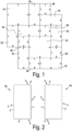
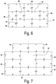
- FIGS 1 , 6 to 8 and 10 different embodiments of sets of floor panels are shown. Only in the first embodiment as shown in figure 1 , the set of floor panels comprises the first, the second, the third and the fourth type of panels. In the other embodiments 6 to 8 and 10, at least one of the second, third or fourth type of panels is missing. However, since the embodiments shown in figures 6 to 8 and 10 are only a part of the pattern of the floor covering, also said not shown types of panels could be present.
- the figures 1 and 6 to 8 and 10 show possible laying patterns, of course other laying patters are not excluded. The main advantage of the invention is that lots of laying patterns are possible.
- said first type of panels 1A extend according to a first direction and said fourth type of panels 1D extend according to a second direction, wherein the second direction is perpendicular to the first direction.
- the coupling parts 6-7-8-9 comprise interlocking parts which, in a mutually coupled position of panels, bring about an interlocking in a horizontal direction H and an interlocking in a vertical direction V.
- the coupling parts 6-7-8-9 comprise interlocking parts which, in a mutually coupled position of panels, bring about an interlocking in a horizontal direction H and an interlocking in a vertical direction V.
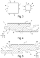
- FIGS 4 and 5 possible options of the long edges 2-3 of the first and fourth type of panels, and possible options for the first pair of edges 2-3 of the second and third type of panels are shown.
- the short edges 4-5 of the first and fourth type of panels and/or the second opposite edges 4-5 of the second and third type of panels can be like this.
- the coupling parts 6-7-8-9 then all allow the panels from the set to be coupled together by means of a rotating movement (W) and/or a horizontal shifting movement, preferably a horizontal shifting movement with snap-effect.
- W rotating movement
- G position of the female part
- the coupling parts 8-9 of the short edges 4-5 and/or second opposite edges 4-5 allow coupling of the fold-down type.
- other embodiments for the coupling parts are possible.
- the female coupling part 7 of the long edge 3 comprises a lateral groove 10 which is delimited by an upper lip 11 and a bottom lip 12, the bottom lip 12 extends distally beyond the upper lip 11 and is provided with an upwardly pointing interlocking part 13; and the male coupling part 6 of the long edge 2 is provided with a tongue 14 which, in the coupled position, can cooperate with the abovementioned lateral groove 10 in order to bring about a vertical interlocking and is provided with a downward directed interlocking groove 15 which, in the coupled position, can cooperate with the abovementioned upwardly pointing interlocking part 13.
- recesses 16A, 16B are present on both long edges 2, 3 which are provided to form a joint/seam which can be grouted.
- the short edges 4, 5 are also provided with similar recesses.
- ceramic tiles can be very well mimicked, this because said formed joints/seams are grouted when the panels are installed, as such resembling grouted ceramic tiles.
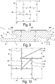
- Figure 10 show an installation pattern comprising three such types of panels and further two panels of the type as shown in figure 9 .
- the female coupling part 7 of the long edge 3 comprises a lateral groove 10 which is delimited by an upper lip 11 and a bottom lip 12, the bottom lip 12 extends distally beyond the upper lip 11 and is provided with an upwardly pointing interlocking part 13; and the male coupling part 6 of the long edge 2 is provided with a tongue 14 which, in the coupled position, can cooperate with the abovementioned lateral groove 10 in order to bring about a vertical interlocking and is provided with a downward directed interlocking groove 15 which, in the coupled position, can cooperate with the abovementioned upwardly pointing interlocking part 13.
- recesses 16A, 16B are present at both edges which are provided to form a joint which can be grouted.
- the panel comprises a central groove/recess 16c, corresponding to said recesses 16A, 16C.
- This groove 16C can run parallel with the two said long edges 2, 3 and is then preferably located centrally between said long edges 2,3.
- Said groove/recess 16C can also run diagonally as can be seen in figure 10 , which shows two panels 1 of the type as shown in figure 9 , namely a square panel and an elongate rectangular panel.
- the set of floor panels comprises the first, the second and the fourth type of panels.
- the panels are at least of the type comprising recesses 16A, 16B, as can be seen in figure 5 , on both long edges 2, 3 and on both the short edges 4, 5 wherein recesses 16A, 16B of two coupled panels form a joint 16 which can be grouted.
- the joint 16 has not been grouted yet.
- two panels 1 are of the type as shown in figure 9 with a groove/recess 16C which has the same width dimension, being the dimension in the plane of the panel 1, as the joints 16. With the aid of such a type of panels 1, ceramic tiles can be very well mimicked, this because said joints 16 and recesses 16C are grouted after laying said panels 1, as such resembling grouted ceramic tiles.
- the invention according to the second aspect relates to a set of floor panels comprising -at least a first type of panels being elongate and rectangular panels 10A comprising a pair of long edges and a pair of short edges; wherein both the long and the short edges are provided with mechanical coupling parts which allow the panels from the set to be coupled together; wherein a first long edge is provided with a male coupling part and a second long edge is provided with a female coupling part; wherein a first short edge is provided with a male coupling part and a second short edge is provided with a female coupling part;
- the coupling parts of the panels of the second aspect of the invention can be as indicated in the first aspect of the invention and/or as indicated in the description and claims.
- the coupling parts comprise interlocking parts which, in a mutually coupled position of panels, bring about an interlocking in a horizontal direction and an interlocking in a vertical direction.
- the coupling parts allow the panels from the set to be coupled together by means of a rotating movement and/or a horizontal shifting movement, preferably a horizontal shifting movement with snap-effect.
- the male part can be indicated as T, which stand for tongue (since the male part can have a tongue) and the position of the female part can be indicated as G, which stand for groove (since the female part can comprise a groove).
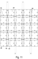
- Figure 11 shows a basketweave pattern. On the edges of this pattern only parts of the first or third type of panels are needed, such that parts will need to be removed. For the edges at the top and at the bottom of the figure, the removed parts are indicated with dashed lines, where at the left and the right side of the figure the removed parts are not indicated with dashed lines. Of course, said removed parts can be used at other locations of the pattern where there is no need for full panels.
- the invention also relates to one or more of the items as listed below:
Landscapes
- Engineering & Computer Science (AREA)
- Architecture (AREA)
- Civil Engineering (AREA)
- Structural Engineering (AREA)
- Floor Finish (AREA)
- Joining Of Building Structures In Genera (AREA)
Applications Claiming Priority (3)
| Application Number | Priority Date | Filing Date | Title |
|---|---|---|---|
| US202363501416P | 2023-05-11 | 2023-05-11 | |
| US202363582252P | 2023-09-13 | 2023-09-13 | |
| US202363603137P | 2023-11-28 | 2023-11-28 |
Publications (2)
| Publication Number | Publication Date |
|---|---|
| EP4461902A2 true EP4461902A2 (de) | 2024-11-13 |
| EP4461902A3 EP4461902A3 (de) | 2024-11-20 |
Family
ID=90810638
Family Applications (1)
| Application Number | Title | Priority Date | Filing Date |
|---|---|---|---|
| EP24171325.4A Pending EP4461902A3 (de) | 2023-05-11 | 2024-04-19 | Satz von paneelen |
Country Status (2)
| Country | Link |
|---|---|
| US (1) | US20240376722A1 (de) |
| EP (1) | EP4461902A3 (de) |
Families Citing this family (2)
| Publication number | Priority date | Publication date | Assignee | Title |
|---|---|---|---|---|
| US20250012086A1 (en) * | 2023-07-03 | 2025-01-09 | Unilin, Bv | Floor or wall covering |
| BE1031978B1 (nl) * | 2023-09-07 | 2025-04-14 | Unilin Bv | Paneel voor het vormen van een bekleding |
Citations (11)
| Publication number | Priority date | Publication date | Assignee | Title |
|---|---|---|---|---|
| WO1997047834A1 (en) | 1996-06-11 | 1997-12-18 | Unilin Beheer B.V. | Floor covering, consisting of hard floor panels and method for manufacturing such floor panels |
| WO2009066153A2 (en) | 2007-11-23 | 2009-05-28 | Flooring Industries Limited, Sarl | Floor panel |
| WO2017068523A1 (en) | 2015-10-23 | 2017-04-27 | Flooring Industries Limited, Sarl | Set of floor panels for forming a floor covering |
| WO2017115202A1 (en) | 2015-12-31 | 2017-07-06 | Flooring Industries Limited, Sarl | Floor panel for forming a floor covering |
| WO2017187298A2 (en) | 2016-04-25 | 2017-11-02 | Flooring Industries Limited, Sarl | Set of floor panels and method for installing this set of floor panels |
| WO2019138365A1 (en) | 2018-01-11 | 2019-07-18 | Flooring Industries Limited, Sarl | Set of floor panels and method for installing this set of floor panels |
| WO2021059062A1 (en) | 2019-09-23 | 2021-04-01 | Flooring Industries Limited, Sarl | Floor or wall covering |
| WO2021070022A1 (en) | 2019-10-08 | 2021-04-15 | Flooring Industries Limited, Sarl | Floor panel for forming a floor covering |
| WO2021105798A1 (en) | 2019-11-25 | 2021-06-03 | Flooring Industries Limited, Sarl | Panel comprising coupling parts |
| WO2021111210A1 (en) | 2019-12-03 | 2021-06-10 | Flooring Industries Limited, Sarl | Floor panel for forming a floor covering |
| WO2022157618A1 (en) | 2021-01-21 | 2022-07-28 | Flooring Industries Limited, Sarl | Set of floor panels and method for installing this set of floor panels |
Family Cites Families (9)
| Publication number | Priority date | Publication date | Assignee | Title |
|---|---|---|---|---|
| US8234834B2 (en) * | 1995-03-07 | 2012-08-07 | Pergo (Europe) Ab | Method for forming a floor |
| SE517009C2 (sv) * | 1999-07-05 | 2002-04-02 | Perstorp Flooring Ab | Golvelement med styrdon |
| US7877956B2 (en) * | 1999-07-05 | 2011-02-01 | Pergo AG | Floor element with guiding means |
| US8250825B2 (en) * | 2001-09-20 | 2012-08-28 | Välinge Innovation AB | Flooring and method for laying and manufacturing the same |
| US7861482B2 (en) * | 2006-07-14 | 2011-01-04 | Valinge Innovation Ab | Locking system comprising a combination lock for panels |
| US10837182B2 (en) * | 2016-11-07 | 2020-11-17 | Berryalloc Nv | Panel and method for manufacturing panels |
| NL2018970B1 (en) * | 2017-05-23 | 2018-12-04 | Innovations 4 Flooring Holding Nv | Multi-purpose tile system |
| CN114514356A (zh) * | 2019-09-25 | 2022-05-17 | 瓦林格创新股份有限公司 | 具有锁定装置的面板 |
| CA3206480A1 (en) * | 2021-02-03 | 2022-08-11 | Valinge Innovation Ab | Building panels comprising a locking device |
-
2024
- 2024-04-19 EP EP24171325.4A patent/EP4461902A3/de active Pending
- 2024-05-07 US US18/656,735 patent/US20240376722A1/en active Pending
Patent Citations (11)
| Publication number | Priority date | Publication date | Assignee | Title |
|---|---|---|---|---|
| WO1997047834A1 (en) | 1996-06-11 | 1997-12-18 | Unilin Beheer B.V. | Floor covering, consisting of hard floor panels and method for manufacturing such floor panels |
| WO2009066153A2 (en) | 2007-11-23 | 2009-05-28 | Flooring Industries Limited, Sarl | Floor panel |
| WO2017068523A1 (en) | 2015-10-23 | 2017-04-27 | Flooring Industries Limited, Sarl | Set of floor panels for forming a floor covering |
| WO2017115202A1 (en) | 2015-12-31 | 2017-07-06 | Flooring Industries Limited, Sarl | Floor panel for forming a floor covering |
| WO2017187298A2 (en) | 2016-04-25 | 2017-11-02 | Flooring Industries Limited, Sarl | Set of floor panels and method for installing this set of floor panels |
| WO2019138365A1 (en) | 2018-01-11 | 2019-07-18 | Flooring Industries Limited, Sarl | Set of floor panels and method for installing this set of floor panels |
| WO2021059062A1 (en) | 2019-09-23 | 2021-04-01 | Flooring Industries Limited, Sarl | Floor or wall covering |
| WO2021070022A1 (en) | 2019-10-08 | 2021-04-15 | Flooring Industries Limited, Sarl | Floor panel for forming a floor covering |
| WO2021105798A1 (en) | 2019-11-25 | 2021-06-03 | Flooring Industries Limited, Sarl | Panel comprising coupling parts |
| WO2021111210A1 (en) | 2019-12-03 | 2021-06-10 | Flooring Industries Limited, Sarl | Floor panel for forming a floor covering |
| WO2022157618A1 (en) | 2021-01-21 | 2022-07-28 | Flooring Industries Limited, Sarl | Set of floor panels and method for installing this set of floor panels |
Also Published As
| Publication number | Publication date |
|---|---|
| US20240376722A1 (en) | 2024-11-14 |
| EP4461902A3 (de) | 2024-11-20 |
Similar Documents
| Publication | Publication Date | Title |
|---|---|---|
| US20250012087A1 (en) | Floor panel for forming a floor covering | |
| KR100990808B1 (ko) | 바닥보오드와 그것을 제조 및 설치하는 방법 및 바닥시공시스템 | |
| EP4461902A2 (de) | Satz von paneelen | |
| US8359806B2 (en) | Floorboards, flooring systems and methods for manufacturing and installation thereof | |
| US8464489B2 (en) | Laminate floor panels | |
| EP2412892B1 (de) | Bodenbelagsysteme und Installationsverfahren | |
| CN101965430B (zh) | 用于铺设地板镶板的方法 | |
| EP1691004B1 (de) | Fussboden mit viereckigen, mechanisch verbindbaren Fussbodenplatten | |
| US8042311B2 (en) | Mechanical locking system for panels and method of installing same | |
| US20130014463A1 (en) | Mechanical locking system for floor panels | |
| UA113738C2 (xx) | Система механічного замкового з'єднання для панелей підлогових покриттів | |
| EP4172429B1 (de) | Fussbodenplatten und verfahren zur herstellung von fussbodenplatten und schneidwerkzeuge dafür | |
| KR20240088931A (ko) | 커버링을 형성하기 위하여 유사 패널들과 상호 연결 가능한 패널 | |
| EP2971401B1 (de) | Bodenplattenanordnung, bodenplatte und verbindungselemente zur verwendung damit | |
| CN101158226B (zh) | 地板块组件、地板系统以及其制造和安装方法 | |
| US20250360646A1 (en) | Set of milling tools and method for manufacturing panels | |
| EA046699B1 (ru) | Набор половых панелей и способ установки этого набора половых панелей | |
| EA052206B1 (ru) | Набор фрезерных инструментов для производства панелей |
Legal Events
| Date | Code | Title | Description |
|---|---|---|---|
| PUAI | Public reference made under article 153(3) epc to a published international application that has entered the european phase |
Free format text: ORIGINAL CODE: 0009012 |
|
| STAA | Information on the status of an ep patent application or granted ep patent |
Free format text: STATUS: THE APPLICATION HAS BEEN PUBLISHED |
|
| PUAL | Search report despatched |
Free format text: ORIGINAL CODE: 0009013 |
|
| AK | Designated contracting states |
Kind code of ref document: A2 Designated state(s): AL AT BE BG CH CY CZ DE DK EE ES FI FR GB GR HR HU IE IS IT LI LT LU LV MC ME MK MT NL NO PL PT RO RS SE SI SK SM TR |
|
| AK | Designated contracting states |
Kind code of ref document: A3 Designated state(s): AL AT BE BG CH CY CZ DE DK EE ES FI FR GB GR HR HU IE IS IT LI LT LU LV MC ME MK MT NL NO PL PT RO RS SE SI SK SM TR |
|
| RIC1 | Information provided on ipc code assigned before grant |
Ipc: E04F 15/10 20060101ALI20241017BHEP Ipc: E04F 15/02 20060101ALI20241017BHEP Ipc: E04F 13/08 20060101AFI20241017BHEP |
|
| STAA | Information on the status of an ep patent application or granted ep patent |
Free format text: STATUS: REQUEST FOR EXAMINATION WAS MADE |
|
| 17P | Request for examination filed |
Effective date: 20250516 |
|
| P01 | Opt-out of the competence of the unified patent court (upc) registered |
Free format text: CASE NUMBER: UPC_APP_0013179_4461902/2025 Effective date: 20251113 |