EP4461694A1 - Rear wheel lift for motorcycles - Google Patents
Rear wheel lift for motorcycles Download PDFInfo
- Publication number
- EP4461694A1 EP4461694A1 EP24382323.4A EP24382323A EP4461694A1 EP 4461694 A1 EP4461694 A1 EP 4461694A1 EP 24382323 A EP24382323 A EP 24382323A EP 4461694 A1 EP4461694 A1 EP 4461694A1
- Authority
- EP
- European Patent Office
- Prior art keywords
- motorcycles
- strut
- rear wheel
- claws
- wheel lift
- Prior art date
- Legal status (The legal status is an assumption and is not a legal conclusion. Google has not performed a legal analysis and makes no representation as to the accuracy of the status listed.)
- Withdrawn
Links
Images

Classifications
-
- B—PERFORMING OPERATIONS; TRANSPORTING
- B66—HOISTING; LIFTING; HAULING
- B66F—HOISTING, LIFTING, HAULING OR PUSHING, NOT OTHERWISE PROVIDED FOR, e.g. DEVICES WHICH APPLY A LIFTING OR PUSHING FORCE DIRECTLY TO THE SURFACE OF A LOAD
- B66F3/00—Devices, e.g. jacks, adapted for uninterrupted lifting of loads
- B66F3/005—Devices, e.g. jacks, adapted for uninterrupted lifting of loads with rocking arm or sector
Definitions
- the present invention relates to a rear wheel lift for motorcycles, of simple configuration that facilitates working with the rear wheel of the motorcycle safely.
- some motorcycle rear wheel lifts which have a U-shaped configuration, where the ends of the branches of the U rest on the swing-arm, on both sides of the wheel, liftable the motorcycle completely vertically by means of operation by a single person. This leads to having to hold the stand with one hand and the motorcycle with the other hand, with the danger of the motorcycle falling to the ground.
- the rear wheel lift for motorcycles of the invention comprises:
- the swing-arm or rear axle on the side opposite the crowbar can be accommodated in the cradle of the liftable extension, with the claws of the base directed to the area under the swing-arm and even under the wheel, and by means of the drive element raise the liftable extension, which will cause the motorcycle to rest on the crowbar, front wheel and lift, with the rear wheel raised from the ground to be able to work with it.
- the slightly inclined position when the motorcycle is raised facilitates work on the lower side of that side, such as loosening the axle nut, loosening plugs, etc. But above all the motorcycle is raised safely, by resting the base below the plane that contains the support point on the swing-arm.
- the lift (1) for motorcycles (2) of the invention comprises:
- the claws (4) have a divergent configuration and a minimum length of 10 centimetres measured perpendicularly from the strut (7). This increases compactness, since the larger the size of the bike, the larger the wheel and the greater the separation between the claws will be necessary and with this divergence the necessary space is achieved without affecting an excessive size of the base.
- the base (3) extends on the side opposite the claws (4) another 5 or 10 centimetres, to increase stability, thus the strut (7) being fixed to a crosspiece (8) arranged between the claws (4) in an intermediate position.
- the liftable extension (9) is telescopically coupled to the strut (7), which produces a self-centring of both elements, with the guidance of the liftable extension and increase in the stability of the lift of the motorcycle.
- the liftable extension (9) has a height between 22 and 30 centimetres, with a most preferred height of 26 centimetres. With this, heights of the support cradle of the swing-arm between 26 and 32 centimetres can be achieved.
Landscapes
- Life Sciences & Earth Sciences (AREA)
- Engineering & Computer Science (AREA)
- Geology (AREA)
- Mechanical Engineering (AREA)
- Structural Engineering (AREA)
- Axle Suspensions And Sidecars For Cycles (AREA)
- Steering Devices For Bicycles And Motorcycles (AREA)
Abstract
Lift (1) for motorcycles (2) of the invention comprising:- a base (3) with two claws (4) spaced from each other at a distance equal to or greater than the area of contact and influence of the wheel (5) with the ground,- a strut (7) arranged between the claws (4),- a liftable extension (9) coupled to the strut (7), and provided with an upper accommodation cradle (10) for the axle, swing-arm (20) or part of the motorcycle to be lifted (2), and- an L-shaped lever (11), with a lower arm (110) attached to the liftable extension (9) of the strut (7) by means of a joint (114), and an upper arm (111) for actuation; comprising connection rods (12) that articulate the lower arm (110) to the base (3).
Description
- The present invention relates to a rear wheel lift for motorcycles, of simple configuration that facilitates working with the rear wheel of the motorcycle safely.
- At present, to carry out certain work with motorcycles, such as changing brake pads, applying inflation pressure or lubricating the chain, this work is facilitated by the rear wheel is in the air, that is, not resting on the ground, since this allows it to rotate freely. Although some motorcycles have a stand, where the rear wheel is raised, other motorcycles do not have it, or the motorcycle is simply too heavy to be able to lifted onto the stand easily.
- In relation to the invention, some motorcycle rear wheel lifts are known, which have a U-shaped configuration, where the ends of the branches of the U rest on the swing-arm, on both sides of the wheel, liftable the motorcycle completely vertically by means of operation by a single person. This leads to having to hold the stand with one hand and the motorcycle with the other hand, with the danger of the motorcycle falling to the ground.
- The rear wheel lift for motorcycles of the invention comprises:
- a base with two claws separated from each other at a distance equal to or greater than the zone of contact and influence of the wheel with the ground, wherein said zone of influence being the one where the wheel and the claws of the base can coexist spatially,
- a strut arranged between the claws,
- a liftable extension coupled to the strut, and provided with an upper accommodation cradle for the axle, swing-arm or part to be lifted of the motorcycle, and
- an L-shaped lever, with a lower arm attached to the liftable extension of the strut by means of a joint, and an upper arm for actuation; comprising rods for articulating the lower arm to the base.
- In this way, with the motorcycle resting on the crowbar, the swing-arm or rear axle on the side opposite the crowbar can be accommodated in the cradle of the liftable extension, with the claws of the base directed to the area under the swing-arm and even under the wheel, and by means of the drive element raise the liftable extension, which will cause the motorcycle to rest on the crowbar, front wheel and lift, with the rear wheel raised from the ground to be able to work with it. With this configuration we have an economical and also compact lift that allows working with the rear wheel. In addition, the slightly inclined position when the motorcycle is raised facilitates work on the lower side of that side, such as loosening the axle nut, loosening plugs, etc. But above all the motorcycle is raised safely, by resting the base below the plane that contains the support point on the swing-arm.
-
-
Figures 1 and 2 show views of the lift of the invention with the liftable extension in a lower and upper position respectively. -
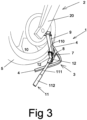
Figure 3 shows a view of the lift of the invention in a raised position, raising the swing-arm of a motorcycle on the opposite side to the side foot. - The lift (1) for motorcycles (2) of the invention comprises:
- a base (3) with two claws (4) spaced from each other at a distance equal to or greater than the area of contact and influence of the wheel (5) with the ground,
- a strut (7) arranged between the claws (4),
- a liftable extension (9) coupled to the strut (7), and provided with an upper accommodation cradle (10) for the axle, swing-arm (20) or part of the motorcycle to be lifted (2), and
- an L-shaped lever (11), with a lower arm (110) attached to the liftable extension (9) of the strut (7) by means of a joint (114), and an upper arm (111) for actuation with an end grip (112); comprising rods (12) for articulating the lower arm (110) to the base (3). The joint (114) can have several fixing points (114a) to the liftable extension (9), as a slider that allows adjusting the actuation height thereof, the liftable extension (9) comprising said fixing points (114a) in lateral lugs (90).
- It is a preferred embodiment of the invention that the claws (4) have a divergent configuration and a minimum length of 10 centimetres measured perpendicularly from the strut (7). This increases compactness, since the larger the size of the bike, the larger the wheel and the greater the separation between the claws will be necessary and with this divergence the necessary space is achieved without affecting an excessive size of the base. Likewise, the base (3) extends on the side opposite the claws (4) another 5 or 10 centimetres, to increase stability, thus the strut (7) being fixed to a crosspiece (8) arranged between the claws (4) in an intermediate position.
- This indicates that it is a preferred embodiment that the liftable extension (9) is telescopically coupled to the strut (7), which produces a self-centring of both elements, with the guidance of the liftable extension and increase in the stability of the lift of the motorcycle.
- It is a preferred embodiment that the liftable extension (9) has a height between 22 and 30 centimetres, with a most preferred height of 26 centimetres. With this, heights of the support cradle of the swing-arm between 26 and 32 centimetres can be achieved.
- Having sufficiently described the nature of the invention, as well as the manner in which it is carried out in practice, it should be noted that the provisions indicated above and shown in the accompanying drawings are subject to modifications in details insofar as they do not alter the essence of the invention.
Claims (7)
- - Rear wheel lift (1) for motorcycles (2); characterised in that it comprises:- a base (3) with two claws (4) spaced from each other at a distance equal to or greater than the area of contact and influence of the wheel (5) with the ground,- a strut (7) arranged between the claws (4),- a liftable extension (9) coupled to the strut (7), and provided with an upper accommodation cradle (10) for the axle, swing-arm (20) or part of the motorcycle to be lifted (2), and- an L-shaped lever (11), with a lower arm (110) attached to the liftable extension (9) of the strut (7) by means of a joint (114), and an upper arm (111) for actuation; comprising connection rods (12) that articulate the lower arm (110) to the base (3).
- - Rear wheel lift (1) for motorcycles (2) according to claim 1, wherein the joint (114) comprises several fixing points (114a) to the liftable extension (9); the liftable extension (9) comprising said fixing points (114a) on lateral lugs (90).
- Rear wheel lift (1) for motorcycles (2) according to claim 1 or 2, wherein the claws (4) have a divergent configuration and a minimum length of 10 centimetres measured perpendicularly from the strut (7).
- Rear wheel lift (1) for motorcycles (2) according to any of the preceding claims, wherein the liftable extension (9) is telescopically coupled to the strut.
- Rear wheel lift (1) for motorcycles (2) according to any of the preceding claims, wherein the strut (7) is fixed to a crossbar (8) arranged between the claws (4) in an intermediate position.
- Rear wheel lift (1) for motorcycles (2) according to any of the preceding claims, wherein the liftable extension (9) has a height of between 22 and 30 centimetres.
- Rear wheel lift (1) for motorcycles (2) according to claim 6, wherein the liftable extension (9) has a height of 26 centimetres.
Applications Claiming Priority (1)
| Application Number | Priority Date | Filing Date | Title |
|---|---|---|---|
| ES202330816U ES1301728Y (en) | 2023-05-10 | 2023-05-10 | REAR WHEEL LIFT FOR MOTORCYCLES |
Publications (1)
| Publication Number | Publication Date |
|---|---|
| EP4461694A1 true EP4461694A1 (en) | 2024-11-13 |
Family
ID=87059824
Family Applications (1)
| Application Number | Title | Priority Date | Filing Date |
|---|---|---|---|
| EP24382323.4A Withdrawn EP4461694A1 (en) | 2023-05-10 | 2024-03-25 | Rear wheel lift for motorcycles |
Country Status (2)
| Country | Link |
|---|---|
| EP (1) | EP4461694A1 (en) |
| ES (1) | ES1301728Y (en) |
Citations (2)
| Publication number | Priority date | Publication date | Assignee | Title |
|---|---|---|---|---|
| US666014A (en) * | 1900-01-27 | 1901-01-15 | Arthur M Kauffman | Wagon-jack. |
| CZ307204B6 (en) * | 2009-10-23 | 2018-03-21 | Ekotez, Spol. S.R.O. | A system of a rest and an external lifting stand for a motorcycle |
-
2023
- 2023-05-10 ES ES202330816U patent/ES1301728Y/en active Active
-
2024
- 2024-03-25 EP EP24382323.4A patent/EP4461694A1/en not_active Withdrawn
Patent Citations (2)
| Publication number | Priority date | Publication date | Assignee | Title |
|---|---|---|---|---|
| US666014A (en) * | 1900-01-27 | 1901-01-15 | Arthur M Kauffman | Wagon-jack. |
| CZ307204B6 (en) * | 2009-10-23 | 2018-03-21 | Ekotez, Spol. S.R.O. | A system of a rest and an external lifting stand for a motorcycle |
Also Published As
| Publication number | Publication date |
|---|---|
| ES1301728U (en) | 2023-07-10 |
| ES1301728Y (en) | 2023-09-29 |
Similar Documents
| Publication | Publication Date | Title |
|---|---|---|
| US4420164A (en) | Stand for dirt bikes | |
| US5678804A (en) | Jacking device for lawn mowing equipment | |
| US7597524B2 (en) | Automobile jack and wheel dolly | |
| CN102234083A (en) | Lifting equipment | |
| SE449482B (en) | DEVICE FOR OPENING THE BRAKE FORM OF INDUSTRIAL TRUCKS | |
| SE508201C2 (en) | Vehicles with hand-operated wheels | |
| US20200276871A1 (en) | Device for unseating tire beads from rims | |
| US6511080B2 (en) | Fork lift trolley | |
| DE60110416D1 (en) | MOTORCYCLE STAND FOR MAINTENANCE | |
| US5145154A (en) | Self contained power assist lift jack | |
| US20060045708A1 (en) | Patient lift with three-point vertical stance | |
| US7104554B2 (en) | Devices and methods for servicing vehicles having tires | |
| JP7307415B2 (en) | Work cart for agricultural work | |
| ES1301728U (en) | REAR WHEEL LIFT FOR MOTORCYCLES (Machine-translation by Google Translate, not legally binding) | |
| EP2298617A1 (en) | Brake mechanism of a hydraulic pallet truck | |
| US7000901B1 (en) | Motorcycle stand | |
| FI90215C (en) | A device to facilitate the installation and removal of vehicle wheels | |
| EP0205265A2 (en) | Vehicle for aerial working | |
| CN103030083A (en) | lifting device | |
| CN109467019A (en) | Lever accident vehicle lifting device | |
| US2424852A (en) | Carrier | |
| US3361408A (en) | Vehicle jack | |
| CA3018479A1 (en) | Tire caddy | |
| KR101547507B1 (en) | High-Rise Working Vehicle Having Detachable Attachment | |
| EP0295066B1 (en) | Vehicle jacks |
Legal Events
| Date | Code | Title | Description |
|---|---|---|---|
| PUAI | Public reference made under article 153(3) epc to a published international application that has entered the european phase |
Free format text: ORIGINAL CODE: 0009012 |
|
| STAA | Information on the status of an ep patent application or granted ep patent |
Free format text: STATUS: THE APPLICATION HAS BEEN PUBLISHED |
|
| AK | Designated contracting states |
Kind code of ref document: A1 Designated state(s): AL AT BE BG CH CY CZ DE DK EE ES FI FR GB GR HR HU IE IS IT LI LT LU LV MC ME MK MT NL NO PL PT RO RS SE SI SK SM TR |
|
| STAA | Information on the status of an ep patent application or granted ep patent |
Free format text: STATUS: THE APPLICATION IS DEEMED TO BE WITHDRAWN |
|
| 18D | Application deemed to be withdrawn |
Effective date: 20250514 |